EP2643868B1 - Housing for mercury-free button cells - Google Patents
Housing for mercury-free button cells Download PDFInfo
- Publication number
- EP2643868B1 EP2643868B1 EP11788797.6A EP11788797A EP2643868B1 EP 2643868 B1 EP2643868 B1 EP 2643868B1 EP 11788797 A EP11788797 A EP 11788797A EP 2643868 B1 EP2643868 B1 EP 2643868B1
- Authority
- EP
- European Patent Office
- Prior art keywords
- layer
- copper
- zinc
- tin
- composite material
- Prior art date
- Legal status (The legal status is an assumption and is not a legal conclusion. Google has not performed a legal analysis and makes no representation as to the accuracy of the status listed.)
- Active
Links
- RYGMFSIKBFXOCR-UHFFFAOYSA-N Copper Chemical compound [Cu] RYGMFSIKBFXOCR-UHFFFAOYSA-N 0.000 claims description 38
- 229910052802 copper Inorganic materials 0.000 claims description 35
- 239000010949 copper Substances 0.000 claims description 35
- PXHVJJICTQNCMI-UHFFFAOYSA-N Nickel Chemical compound [Ni] PXHVJJICTQNCMI-UHFFFAOYSA-N 0.000 claims description 22
- HCHKCACWOHOZIP-UHFFFAOYSA-N Zinc Chemical compound [Zn] HCHKCACWOHOZIP-UHFFFAOYSA-N 0.000 claims description 21
- 229910052751 metal Inorganic materials 0.000 claims description 21
- 239000002184 metal Substances 0.000 claims description 21
- ATJFFYVFTNAWJD-UHFFFAOYSA-N Tin Chemical compound [Sn] ATJFFYVFTNAWJD-UHFFFAOYSA-N 0.000 claims description 19
- 229910052718 tin Inorganic materials 0.000 claims description 19
- 229910052725 zinc Inorganic materials 0.000 claims description 19
- 239000011701 zinc Substances 0.000 claims description 19
- 239000002131 composite material Substances 0.000 claims description 17
- JCXGWMGPZLAOME-UHFFFAOYSA-N bismuth atom Chemical compound [Bi] JCXGWMGPZLAOME-UHFFFAOYSA-N 0.000 claims description 15
- 229910052738 indium Inorganic materials 0.000 claims description 15
- APFVFJFRJDLVQX-UHFFFAOYSA-N indium atom Chemical compound [In] APFVFJFRJDLVQX-UHFFFAOYSA-N 0.000 claims description 15
- 150000002739 metals Chemical class 0.000 claims description 14
- 229910000831 Steel Inorganic materials 0.000 claims description 12
- 238000000034 method Methods 0.000 claims description 12
- 239000010959 steel Substances 0.000 claims description 12
- 229910052797 bismuth Inorganic materials 0.000 claims description 11
- 229910052759 nickel Inorganic materials 0.000 claims description 10
- 229910045601 alloy Inorganic materials 0.000 claims description 9
- 239000000956 alloy Substances 0.000 claims description 9
- 229910000881 Cu alloy Inorganic materials 0.000 claims description 7
- 238000010438 heat treatment Methods 0.000 claims description 6
- 238000004519 manufacturing process Methods 0.000 claims description 3
- 238000007493 shaping process Methods 0.000 claims 1
- RNWHGQJWIACOKP-UHFFFAOYSA-N zinc;oxygen(2-) Chemical compound [O-2].[Zn+2] RNWHGQJWIACOKP-UHFFFAOYSA-N 0.000 description 10
- 238000009792 diffusion process Methods 0.000 description 7
- UFHFLCQGNIYNRP-UHFFFAOYSA-N Hydrogen Chemical compound [H][H] UFHFLCQGNIYNRP-UHFFFAOYSA-N 0.000 description 6
- 229910052739 hydrogen Inorganic materials 0.000 description 6
- 239000001257 hydrogen Substances 0.000 description 6
- KUNSUQLRTQLHQQ-UHFFFAOYSA-N copper tin Chemical compound [Cu].[Sn] KUNSUQLRTQLHQQ-UHFFFAOYSA-N 0.000 description 5
- QSHDDOUJBYECFT-UHFFFAOYSA-N mercury Chemical compound [Hg] QSHDDOUJBYECFT-UHFFFAOYSA-N 0.000 description 5
- 238000009713 electroplating Methods 0.000 description 4
- 229910052753 mercury Inorganic materials 0.000 description 4
- 229910001220 stainless steel Inorganic materials 0.000 description 4
- 239000010935 stainless steel Substances 0.000 description 4
- KWYUFKZDYYNOTN-UHFFFAOYSA-M Potassium hydroxide Chemical compound [OH-].[K+] KWYUFKZDYYNOTN-UHFFFAOYSA-M 0.000 description 3
- 239000003792 electrolyte Substances 0.000 description 3
- 239000007789 gas Substances 0.000 description 3
- 240000008121 Tridax procumbens Species 0.000 description 2
- 230000000694 effects Effects 0.000 description 2
- 239000011888 foil Substances 0.000 description 2
- AMWRITDGCCNYAT-UHFFFAOYSA-L hydroxy(oxo)manganese;manganese Chemical compound [Mn].O[Mn]=O.O[Mn]=O AMWRITDGCCNYAT-UHFFFAOYSA-L 0.000 description 2
- 239000000463 material Substances 0.000 description 2
- 238000004080 punching Methods 0.000 description 2
- NDVLTYZPCACLMA-UHFFFAOYSA-N silver oxide Chemical compound [O-2].[Ag+].[Ag+] NDVLTYZPCACLMA-UHFFFAOYSA-N 0.000 description 2
- 240000003517 Elaeocarpus dentatus Species 0.000 description 1
- 229910000846 In alloy Inorganic materials 0.000 description 1
- 229910001209 Low-carbon steel Inorganic materials 0.000 description 1
- 229910001297 Zn alloy Inorganic materials 0.000 description 1
- PDYXSJSAMVACOH-UHFFFAOYSA-N [Cu].[Zn].[Sn] Chemical compound [Cu].[Zn].[Sn] PDYXSJSAMVACOH-UHFFFAOYSA-N 0.000 description 1
- 230000015572 biosynthetic process Effects 0.000 description 1
- 238000005253 cladding Methods 0.000 description 1
- HVMJUDPAXRRVQO-UHFFFAOYSA-N copper indium Chemical compound [Cu].[In] HVMJUDPAXRRVQO-UHFFFAOYSA-N 0.000 description 1
- TVZPLCNGKSPOJA-UHFFFAOYSA-N copper zinc Chemical compound [Cu].[Zn] TVZPLCNGKSPOJA-UHFFFAOYSA-N 0.000 description 1
- 238000002788 crimping Methods 0.000 description 1
- 238000005520 cutting process Methods 0.000 description 1
- 230000007423 decrease Effects 0.000 description 1
- 230000001419 dependent effect Effects 0.000 description 1
- 238000001035 drying Methods 0.000 description 1
- 238000004070 electrodeposition Methods 0.000 description 1
- 230000007613 environmental effect Effects 0.000 description 1
- 239000012212 insulator Substances 0.000 description 1
- 238000004021 metal welding Methods 0.000 description 1
- 239000000203 mixture Substances 0.000 description 1
- 238000007747 plating Methods 0.000 description 1
- 239000002244 precipitate Substances 0.000 description 1
- 230000001105 regulatory effect Effects 0.000 description 1
- 230000000630 rising effect Effects 0.000 description 1
- 238000005096 rolling process Methods 0.000 description 1
- 229910001923 silver oxide Inorganic materials 0.000 description 1
- 230000001988 toxicity Effects 0.000 description 1
- 231100000419 toxicity Toxicity 0.000 description 1
- XLYOFNOQVPJJNP-UHFFFAOYSA-N water Substances O XLYOFNOQVPJJNP-UHFFFAOYSA-N 0.000 description 1
Images
Classifications
-
- H—ELECTRICITY
- H01—ELECTRIC ELEMENTS
- H01M—PROCESSES OR MEANS, e.g. BATTERIES, FOR THE DIRECT CONVERSION OF CHEMICAL ENERGY INTO ELECTRICAL ENERGY
- H01M50/00—Constructional details or processes of manufacture of the non-active parts of electrochemical cells other than fuel cells, e.g. hybrid cells
- H01M50/10—Primary casings, jackets or wrappings of a single cell or a single battery
- H01M50/102—Primary casings, jackets or wrappings of a single cell or a single battery characterised by their shape or physical structure
- H01M50/109—Primary casings, jackets or wrappings of a single cell or a single battery characterised by their shape or physical structure of button or coin shape
-
- H—ELECTRICITY
- H01—ELECTRIC ELEMENTS
- H01M—PROCESSES OR MEANS, e.g. BATTERIES, FOR THE DIRECT CONVERSION OF CHEMICAL ENERGY INTO ELECTRICAL ENERGY
- H01M6/00—Primary cells; Manufacture thereof
- H01M6/04—Cells with aqueous electrolyte
-
- H—ELECTRICITY
- H01—ELECTRIC ELEMENTS
- H01M—PROCESSES OR MEANS, e.g. BATTERIES, FOR THE DIRECT CONVERSION OF CHEMICAL ENERGY INTO ELECTRICAL ENERGY
- H01M50/00—Constructional details or processes of manufacture of the non-active parts of electrochemical cells other than fuel cells, e.g. hybrid cells
- H01M50/10—Primary casings, jackets or wrappings of a single cell or a single battery
- H01M50/116—Primary casings, jackets or wrappings of a single cell or a single battery characterised by the material
- H01M50/117—Inorganic material
- H01M50/119—Metals
-
- H—ELECTRICITY
- H01—ELECTRIC ELEMENTS
- H01M—PROCESSES OR MEANS, e.g. BATTERIES, FOR THE DIRECT CONVERSION OF CHEMICAL ENERGY INTO ELECTRICAL ENERGY
- H01M50/00—Constructional details or processes of manufacture of the non-active parts of electrochemical cells other than fuel cells, e.g. hybrid cells
- H01M50/10—Primary casings, jackets or wrappings of a single cell or a single battery
- H01M50/116—Primary casings, jackets or wrappings of a single cell or a single battery characterised by the material
- H01M50/124—Primary casings, jackets or wrappings of a single cell or a single battery characterised by the material having a layered structure
- H01M50/1243—Primary casings, jackets or wrappings of a single cell or a single battery characterised by the material having a layered structure characterised by the internal coating on the casing
-
- H—ELECTRICITY
- H01—ELECTRIC ELEMENTS
- H01M—PROCESSES OR MEANS, e.g. BATTERIES, FOR THE DIRECT CONVERSION OF CHEMICAL ENERGY INTO ELECTRICAL ENERGY
- H01M50/00—Constructional details or processes of manufacture of the non-active parts of electrochemical cells other than fuel cells, e.g. hybrid cells
- H01M50/10—Primary casings, jackets or wrappings of a single cell or a single battery
- H01M50/116—Primary casings, jackets or wrappings of a single cell or a single battery characterised by the material
- H01M50/124—Primary casings, jackets or wrappings of a single cell or a single battery characterised by the material having a layered structure
- H01M50/126—Primary casings, jackets or wrappings of a single cell or a single battery characterised by the material having a layered structure comprising three or more layers
- H01M50/128—Primary casings, jackets or wrappings of a single cell or a single battery characterised by the material having a layered structure comprising three or more layers with two or more layers of only inorganic material
-
- H—ELECTRICITY
- H01—ELECTRIC ELEMENTS
- H01M—PROCESSES OR MEANS, e.g. BATTERIES, FOR THE DIRECT CONVERSION OF CHEMICAL ENERGY INTO ELECTRICAL ENERGY
- H01M50/00—Constructional details or processes of manufacture of the non-active parts of electrochemical cells other than fuel cells, e.g. hybrid cells
- H01M50/10—Primary casings, jackets or wrappings of a single cell or a single battery
- H01M50/147—Lids or covers
- H01M50/148—Lids or covers characterised by their shape
- H01M50/1535—Lids or covers characterised by their shape adapted for specific cells, e.g. electrochemical cells operating at high temperature
- H01M50/1537—Lids or covers characterised by their shape adapted for specific cells, e.g. electrochemical cells operating at high temperature for hybrid cells
-
- H—ELECTRICITY
- H01—ELECTRIC ELEMENTS
- H01M—PROCESSES OR MEANS, e.g. BATTERIES, FOR THE DIRECT CONVERSION OF CHEMICAL ENERGY INTO ELECTRICAL ENERGY
- H01M50/00—Constructional details or processes of manufacture of the non-active parts of electrochemical cells other than fuel cells, e.g. hybrid cells
- H01M50/10—Primary casings, jackets or wrappings of a single cell or a single battery
- H01M50/147—Lids or covers
- H01M50/155—Lids or covers characterised by the material
- H01M50/157—Inorganic material
- H01M50/159—Metals
-
- H—ELECTRICITY
- H01—ELECTRIC ELEMENTS
- H01M—PROCESSES OR MEANS, e.g. BATTERIES, FOR THE DIRECT CONVERSION OF CHEMICAL ENERGY INTO ELECTRICAL ENERGY
- H01M50/00—Constructional details or processes of manufacture of the non-active parts of electrochemical cells other than fuel cells, e.g. hybrid cells
- H01M50/10—Primary casings, jackets or wrappings of a single cell or a single battery
- H01M50/147—Lids or covers
- H01M50/155—Lids or covers characterised by the material
- H01M50/164—Lids or covers characterised by the material having a layered structure
-
- H—ELECTRICITY
- H01—ELECTRIC ELEMENTS
- H01M—PROCESSES OR MEANS, e.g. BATTERIES, FOR THE DIRECT CONVERSION OF CHEMICAL ENERGY INTO ELECTRICAL ENERGY
- H01M6/00—Primary cells; Manufacture thereof
- H01M6/04—Cells with aqueous electrolyte
- H01M6/06—Dry cells, i.e. cells wherein the electrolyte is rendered non-fluid
- H01M6/12—Dry cells, i.e. cells wherein the electrolyte is rendered non-fluid with flat electrodes
-
- H—ELECTRICITY
- H01—ELECTRIC ELEMENTS
- H01M—PROCESSES OR MEANS, e.g. BATTERIES, FOR THE DIRECT CONVERSION OF CHEMICAL ENERGY INTO ELECTRICAL ENERGY
- H01M12/00—Hybrid cells; Manufacture thereof
- H01M12/04—Hybrid cells; Manufacture thereof composed of a half-cell of the fuel-cell type and of a half-cell of the primary-cell type
- H01M12/06—Hybrid cells; Manufacture thereof composed of a half-cell of the fuel-cell type and of a half-cell of the primary-cell type with one metallic and one gaseous electrode
-
- H—ELECTRICITY
- H01—ELECTRIC ELEMENTS
- H01M—PROCESSES OR MEANS, e.g. BATTERIES, FOR THE DIRECT CONVERSION OF CHEMICAL ENERGY INTO ELECTRICAL ENERGY
- H01M50/00—Constructional details or processes of manufacture of the non-active parts of electrochemical cells other than fuel cells, e.g. hybrid cells
- H01M50/10—Primary casings, jackets or wrappings of a single cell or a single battery
- H01M50/116—Primary casings, jackets or wrappings of a single cell or a single battery characterised by the material
- H01M50/124—Primary casings, jackets or wrappings of a single cell or a single battery characterised by the material having a layered structure
- H01M50/1245—Primary casings, jackets or wrappings of a single cell or a single battery characterised by the material having a layered structure characterised by the external coating on the casing
-
- H—ELECTRICITY
- H01—ELECTRIC ELEMENTS
- H01M—PROCESSES OR MEANS, e.g. BATTERIES, FOR THE DIRECT CONVERSION OF CHEMICAL ENERGY INTO ELECTRICAL ENERGY
- H01M50/00—Constructional details or processes of manufacture of the non-active parts of electrochemical cells other than fuel cells, e.g. hybrid cells
- H01M50/10—Primary casings, jackets or wrappings of a single cell or a single battery
- H01M50/147—Lids or covers
- H01M50/166—Lids or covers characterised by the methods of assembling casings with lids
- H01M50/171—Lids or covers characterised by the methods of assembling casings with lids using adhesives or sealing agents
Definitions
- the present invention relates to a method for producing a cup-shaped Gepurteils provided on the inside with a copper alloy for the housing of a mercury-free button cell.
- Button cells usually have a housing made of two housing halves, a cup cup usually formed cup-shaped and often also cup-shaped cell lid on. These can be made, for example, from nickel-plated deep-drawn sheet metal as punched drawing parts. It is more common, however, to use a clad composite material with a layer of nickel, a layer of copper and an intermediate layer of steel or stainless steel (so-called trimetal) as the housing material. Case half parts of trimetal are, for example, the JP 61061364 A1 refer to. A arranged between the GeHouseschieri plastic ring serves as a rule at the same time as a seal and as an insulator, which separates the housing halves spatially and electrically from each other.
- the cell cup of a coin cell is positively poled and the cell lid negative. The liquid-tight closure of such cells is usually carried out by crimping the edge of the cell cup.
- button cells often contain a paste or gel of zinc powder.
- positive counter electrodes are then, for example, gas diffusion electrodes (for zinc / air cells) or, alternatively, e.g. Manganese oxide or silver oxide in question.
- the electrolyte used in the mentioned electrochemical systems is generally an alkaline electrolyte, in particular concentrated aqueous potassium hydroxide.
- the presence of an alkaline electrolyte has both advantages and disadvantages.
- the disadvantages include, in particular, that zinc in the alkaline medium can react very easily with hydrogen to form hydrogen. As a result of hydrogen evolution, the cell can irreversibly be damaged.
- Til today The reaction of zinc with water in alkaline zinc cells is regulated by the addition of mercury. However, due to the toxicity and environmental harmfulness of mercury, this approach is no longer an option in the future.
- Mercury-free button cells are known in the prior art, in which the inside of the button cell cover is coated with a layer of a copper-tin, copper-zinc or copper-indium alloy to increase the hydrogen overvoltage and hydrogen evolution even in the absence to keep mercury at an acceptable level.
- the alloys mentioned are less ductile, so that a production of deep-drawn lids without breaking the alloy layer is not possible.
- buttons cell covers made as stamped drawing parts with a layer of a copper-tin-zinc alloy to avoid gassing effects.
- this procedure involves a complex electroplating and a subsequent drying process.
- button cell cover made of trimetal and then coated inside with tin.
- the button cell lids to be coated must be lavishly cleaned.
- the method having the features of claim 1 provides a simple and elegant way of providing button cell caps internally coated with a hydrogen overvoltage increasing alloy.
- a preferred embodiment of the method according to the invention is specified in the dependent claim 2.
- the heat treatment is carried out at a temperature in the range between 200 ° C and 400 ° C. At this temperature, the metals tin, zinc, indium and / or bismuth can diffuse into the layer of copper, corresponding copper alloys of the corresponding form Metals. Since these copper alloys arise only after the formation of the cup-shaped housing half, their low ductility has no negative effects.
- the copper layer and the described additional layer are united in this process to a new layer or layer.
- the new layer or layer preferably does not consist of an alloy having a uniform, uniform composition.
- concentration gradients may instead form depending on the parameters selected during the heat treatment (in particular the parameters "temperature” and "time”). Such gradients can be detected by appropriate analyzes of the heat treated housing halves.
- a diffusion of the metals tin, zinc, indium and bismuth in the copper layer is to a significant extent only from the minimum temperature of 200 ° C, a. Below this temperature, the diffusion kinetics are inhibited too much.
- the heat treatment preferably takes place over a period of between 1 hour and 10 hours.
- the method according to the invention makes it possible to produce cup-shaped housing halves which are produced from a plated composite material comprising a layer of nickel, a layer of steel or stainless steel and a layer comprising copper alloyed with at least one metal selected from tin, zinc, indium and bismuth Layer nickel the outside and the position with the copper alloy forms the inside of the cup-shaped Gezzauseschmaschine.
- the elements zinc, tin, indium and / or bismuth are preferably not found everywhere in the same concentration within the inner layer in preferred embodiments.
- the housing half parts according to the invention are correspondingly also characterized in that inside the layer forming the inside the concentration of copper decreases with increasing distance to the layer of steel and the concentration of the at least one element from the group with zinc, tin, indium and bismuth rising in the same direction.
- the copper is enriched within the layer with the copper alloy to the layer of steel and depleted towards the cup inside.
- Enriched means in the present case that the local content of copper near the steel layer is greater than the average content of copper in the position, while depleted means that the local content of copper towards the cup interior is less than the average content of copper in the layer.
- the average content of copper results from the weight ratio of the proportion of copper in the position to the sum of all parts of the position multiplied by the factor 100.
- the cup-shaped Gezzateil is the cell cover of a button cell, in particular a button cell with a zinc-containing anode, in particular a zinc / air button cell.
- the zinc-containing anode is usually arranged in the cup-shaped Gepurteil invention.
- the layer 111 of copper and the copper-tin alloy forms the inside of the cell cover 101 and is in direct contact with the zinc paste 103.
- the layer 109 of nickel forms the outside of the cell cover.
- the cell lid 101 was manufactured from a copper-side trim added with an additional layer of tin. After punching out the cell lid 101 made of this material, it was heated to a temperature of about 200 ° C. for two hours. It formed from the copper side of the trimetal and the additional layer arranged thereon made of tin, the layer 111 comprising copper and the copper-tin alloy. By diffusion, a concentration gradient formed within the resulting (common) layer 111 . It has been found that within layer 111, copper is enriched for the steel layer. Towards the interior of the bowl, however, the concentration of tin increases. Immediately at the boundary between the layer 110 and the layer 111 , unalloyed copper was even found.
- layer 111 comprising copper and of a copper-tin alloy
- the tin layer on the copper side of the trimetal before the heat treatment had a thickness in the range between 0.2 ⁇ m and 5 ⁇ m.
- the tin layer had been deposited by electroplating on the trimetal.
Description
Die vorliegende Erfindung betrifft ein Verfahren zur Herstellung eines innenseitig mit einer Kupferlegierung versehenen napfförmigen Gehäusehalbteils für das Gehäuse einer quecksilberfreien Knopfzelle.The present invention relates to a method for producing a cup-shaped Gehäusehalbteils provided on the inside with a copper alloy for the housing of a mercury-free button cell.
Knopfzellen weisen üblicherweise ein Gehäuse aus zwei Gehäusehalbteilen, einem in der Regel napfförmig ausgebildeten Zellenbecher und einem häufig ebenfalls napfförmig ausgebildeten Zellendeckel, auf. Diese können beispielsweise aus vernickeltem Tiefziehblech als Stanzziehteile hergestellt werden. Üblicher ist es jedoch, als Gehäusewerkstoff ein plattiertes Verbundmaterial mit einer Lage Nickel, einer Lage Kupfer und einer dazwischenliegenden Lage aus Stahl bzw. Edelstahl zu verwenden (sogenanntes Trimetall). Gehäusehalbteile aus Trimetall sind beispielsweise der
Als negative Elektrode enthalten Knopfzellen häufig eine Paste oder ein Gel aus Zinkpulver. Als positive Gegenelektroden kommen dann beispielsweise Gasdiffusionselektroden (für Zink/Luft-Zellen) oder alternativ z.B. Manganoxid oder Silberoxid in Frage.As a negative electrode, button cells often contain a paste or gel of zinc powder. As positive counter electrodes are then, for example, gas diffusion electrodes (for zinc / air cells) or, alternatively, e.g. Manganese oxide or silver oxide in question.
Als Elektrolyt kommt bei den genannten elektrochemischen Systemen in der Regel ein alkalischer Elektrolyt zum Einsatz, insbesondere konzentriertes wässriges Kaliumhydroxid. Die Gegenwart eines alkalischen Elektrolyten hat sowohl Vorteile als auch Nachteile. Zu den Nachteilen gehört insbesondere, dass Zink im alkalischen Milieu sehr leicht unter Wasserstoffbildung mit Wasser reagiert kann. Als Folge der Wasserstoffentwicklung kann die Zelle irreversibel geschädigt werden. Bis heute wird die Reaktion von Zink mit Wasser in alkalischen Zinkzellen durch Zugabe von Quecksilber reguliert. Aufgrund der Giftigkeit und Umweltschädlichkeit von Quecksilber ist diese Vorgehensweise in der Zukunft jedoch keine Option mehr.The electrolyte used in the mentioned electrochemical systems is generally an alkaline electrolyte, in particular concentrated aqueous potassium hydroxide. The presence of an alkaline electrolyte has both advantages and disadvantages. The disadvantages include, in particular, that zinc in the alkaline medium can react very easily with hydrogen to form hydrogen. As a result of hydrogen evolution, the cell can irreversibly be damaged. Til today The reaction of zinc with water in alkaline zinc cells is regulated by the addition of mercury. However, due to the toxicity and environmental harmfulness of mercury, this approach is no longer an option in the future.
Aus dem Stand der Technik sind quecksilberfreie Knopfzellen bekannt, bei denen die Innenseite der Knopfzellendeckel mit einer Schicht aus einer Kupfer-Zinn-, Kupfer-Zink- oder Kupfer-Indium-Legierung überzogen ist, um die Wasserstoffüberspannung zu erhöhen und die Wasserstoffentwickung auch bei Abwesenheit von Quecksilber auf einem akzeptablen Niveau zu halten. Die genannten Legierungen sind jedoch wenig duktil, so dass eine Herstellung von tiefgezogenen Deckeln ohne Aufbrechen der Legierungsschicht nicht möglich ist.Mercury-free button cells are known in the prior art, in which the inside of the button cell cover is coated with a layer of a copper-tin, copper-zinc or copper-indium alloy to increase the hydrogen overvoltage and hydrogen evolution even in the absence to keep mercury at an acceptable level. However, the alloys mentioned are less ductile, so that a production of deep-drawn lids without breaking the alloy layer is not possible.
Aus der
In der
Aus der
Das Verfahren mit den Merkmalen des Anspruchs 1 bietet eine einfache und elegante Möglichkeit zur Bereitstellung von Knopfzellendeckeln, die innenseitig mit einer die Wasserstoffüberspannung erhöhenden Legierung überzogen sind. Eine bevorzugte Ausführungsform des erfindungsgemäßen Verfahrens ist im abhängigen Anspruch 2 angegeben.The method having the features of claim 1 provides a simple and elegant way of providing button cell caps internally coated with a hydrogen overvoltage increasing alloy. A preferred embodiment of the method according to the invention is specified in the dependent claim 2.
Der Wortlaut sämtlicher Ansprüche wird hiermit durch Bezugnahme zum Inhalt dieser Beschreibung gemacht.The wording of all claims is hereby incorporated by reference into the content of this specification.
Das erfindungsgemäße Verfahren dient zur Herstellung eines innenseitig mit einer Kupferlegierung versehenen napfförmigen Gehäusehalbteils für das Gehäuse einer quecksilberfreien (Hg-freien) Knopfzelle. Es umfasst in der Regel die folgenden Schritte:
- (1) In einem Schritt wird ein plattiertes Verbundmaterial bereitgestellt, das eine Lage Nickel, eine Lage Kupfer und eine dazwischenliegende Lage aus Stahl bzw. Edelstahl umfasst. Kupferseitig ist das Verbundmaterial mit einer zusätzlichen Schicht aus einem der Metalle Zinn, Zink, Indium, Bismut oder einer Legierung aus diesen Metallen versehen. Bevorzugt wurde diese zusätzliche Schicht auf die Lage Kupfer aufplattiert.
Mit Plattieren bezeichnet man eine Vorgehensweise in der Metallverarbeitung, bei der ein Metall durch ein weiteres, häufig vergleichsweise edleres, Metall überdeckt wird. Beim obenliegenden Verbundmaterial wird eine Lage Stahl durch Nickel und Kupfer überdeckt. Zwischen den Metallen soll dabei eine möglichst untrennbare Verbindung entstehen. Zur Anwendung kommen hierfür die unterschiedlichsten Techniken wie z.B. das Aufwalzen oder Aufschweißen von Metallfolien oder die elektrochemische Abscheidung von metallischen Niederschlägen. Im letzteren Fall spricht man von Elektroplattieren.
Erfindungsgemäß kommt als Verbundmaterial bevorzugt das bereits eingangs erwähnte Trimetall zum Einsatz. Bei Trimetall handelt es sich um eine Sonderplattierung, die speziell für die Gehäuse von Knopfzellen entwickelt wurde. Als Träger dient in der Regel eine dünne Folie aus niedrig gekohltem Stahl oder nicht rostendem Edelstahl. Die Dicke des Verbundmaterials liegt bevorzugt in dem Bereich zwischen 0,05 µm und 0,25 µm. Die Nickellage beansprucht dabei in der Regel zwischen 1 % und 15 % der Dicke des Verbundmaterials, die Kupferlage zwischen 5 % und 30 %. Der Anteil der Stahlfolie an der Dicke des Verbundmaterials beträgt entsprechend zwischen 55 % und 94 %.
Dazu kommt natürlich noch die erwähnte Schicht aus einem der Metalle Zinn, Zink, Indium, Bismut oder einer Legierung aus diesen Metallen. Diese ist bevorzugt galvanisch auf die Kupferseite des Verbundmaterials aufgebracht, also durch Elektroplattieren. In bevorzugten Ausführungsformen beträgt ihre Dicke im Mittel zwischen 0,5 µm und 2 µm. - (2) Das gemäß (1) bereitgestellte, kupferseitig beschichtete Verbundmaterial liegt bevorzugt in Form eines Endlosbandes vor. Aus dem Verbundmaterial wird im zweiten Schritt ein napfförmiges Gehäusehalbteil geformt, wobei in Übereinstimmung mit den einleitenden Ausführungen zum Stand der Technik die Lage Nickel die Außenseite und die zusätzliche Schicht aus einem der Metalle Zinn, Zink, Indium, Bismut oder einer Legierung aus diesen Metallen die Innenseite des napfförmigen Gehäusehalbteils bildet. Bevorzugt wird das napfförmige Gehäusehalbteil durch einen Tiefzieh- oder Ausstanzprozess gebildet.
- (3) Als weiteren Schritt umfasst das erfindungsgemäße Verfahren eine Wärmebehandlung des gemäß (2) gebildeten Gehäusehalbteils. Diese erfolgt erfindungsgemäß bei einer Temperatur, bei der die zusätzliche Schicht aus einem der Metalle Zinn, Zink, Indium, Bismut oder einer Legierung aus diesen Metallen mit dem Kupfer aus der Lage Kupfer legiert.
- (1) In one step, a clad composite material comprising a layer of nickel, a layer of copper and an intermediate layer of steel or stainless steel is provided. On the copper side, the composite material is provided with an additional layer of one of the metals tin, zinc, indium, bismuth or an alloy of these metals. Preferably, this additional layer was plated on the layer of copper.
Plating refers to a procedure in metal processing in which a metal is covered by another, often relatively noble, metal. In the overhead composite material, a layer of steel is covered by nickel and copper. Between the metals, a most inseparable connection should arise. For this purpose, a variety of techniques such as the rolling or welding of metal foils or the electrochemical deposition of metallic precipitates are used. In the latter case one speaks of electroplating.
According to the invention, the trimetal already mentioned in the introduction is preferably used as the composite material. Trimetallic is a special cladding specially developed for coin cell cases. The carrier is usually a thin sheet of low carbon steel or stainless steel. The thickness of the composite material is preferably in the Range between 0.05 μm and 0.25 μm. The nickel layer usually takes between 1% and 15% of the thickness of the composite material, the copper layer between 5% and 30%. The proportion of steel foil in the thickness of the composite material is correspondingly between 55% and 94%.
Of course, there is also the mentioned layer of one of the metals tin, zinc, indium, bismuth or an alloy of these metals. This is preferably applied galvanically on the copper side of the composite material, ie by electroplating. In preferred embodiments, its thickness is on average between 0.5 μm and 2 μm. - (2) The copper-side coated composite material provided in (1) is preferably in the form of an endless belt. From the composite material, a cup-shaped housing half is formed in the second step, and in accordance with the prior art, the layer of nickel is the outside and the additional layer of one of the metals tin, zinc, indium, bismuth or an alloy of these metals Formed inside the cup-shaped Gehäusehalbteils. Preferably, the cup-shaped Gehäusehalbteil is formed by a deep-drawing or punching process.
- (3) As a further step, the method according to the invention comprises a heat treatment of the housing half-part formed according to (2). This takes place according to the invention at a temperature at which the additional layer of one of the metals tin, zinc, indium, bismuth or an alloy of these metals is alloyed with the copper from the layer of copper.
Die Wärmebehandlung wird bei einer Temperatur im Bereich zwischen 200 °C und 400 °C vorgenommen. Bei dieser Temperatur können die Metalle Zinn, Zink, Indium und/oder Bismut in die Lage Kupfer eindiffundieren, es bilden sich entsprechend Kupferlegierungen der entsprechenden Metalle. Da diese Kupferlegierungen erst nach der Bildung des napfförmigen Gehäusehalbteils entstehen, hat ihre geringe Duktilität keine negativen Auswirkungen.The heat treatment is carried out at a temperature in the range between 200 ° C and 400 ° C. At this temperature, the metals tin, zinc, indium and / or bismuth can diffuse into the layer of copper, corresponding copper alloys of the corresponding form Metals. Since these copper alloys arise only after the formation of the cup-shaped housing half, their low ductility has no negative effects.
Beim Eindiffundieren der genannten Metalle in die Kupferlage des Verbundmaterials verwischen die Grenzen zwischen der Kupferlage und der beschriebenen zusätzlichen Schicht. Die Kupferlage und die beschriebene zusätzliche Schicht werden bei diesem Prozess zu einer neuen Lage oder Schicht vereint.When the said metals diffuse into the copper layer of the composite material, the boundaries between the copper layer and the additional layer described blur. The copper layer and the described additional layer are united in this process to a new layer or layer.
Bevorzugt besteht die neue Lage oder Schicht allerdings nicht aus einer Legierung mit einer gleichmäßigen, einheitlichen Zusammensetzung. Beim erwähnten Eindiffundieren können sich stattdessen in Abhängigkeit der bei der Wärmebehandlung gewählten Parameter (insbesondere der Parameter "Temperatur"und "Zeit") Konzentrationsgradienten bilden. Solche Gradienten sind durch entsprechende Analysen der wärmebehandelten Gehäusehalbteile nachweisbar.However, the new layer or layer preferably does not consist of an alloy having a uniform, uniform composition. In the case of in-diffusion mentioned, concentration gradients may instead form depending on the parameters selected during the heat treatment (in particular the parameters "temperature" and "time"). Such gradients can be detected by appropriate analyzes of the heat treated housing halves.
Eine Diffusion der Metalle Zinn, Zink, Indium und Bismut in die Kupferlage setzt in nennenswertem Umfang erst ab der genannten Mindesttemperatur von 200 °C, ein. Unterhalb dieser Temperatur sind die Diffusionskinetiken zu stark gehemmt.A diffusion of the metals tin, zinc, indium and bismuth in the copper layer is to a significant extent only from the minimum temperature of 200 ° C, a. Below this temperature, the diffusion kinetics are inhibited too much.
Bevorzugt erfolgt die Wärmebehandlung über einen Zeitraum zwischen 1 Stunde und 10 Stunden.The heat treatment preferably takes place over a period of between 1 hour and 10 hours.
Mit dem erfindungsgemäßen Verfahren lassen sich napfförmige Gehäusehalbteile herstellen, die aus einem plattierten Verbundmaterial umfassend eine Lage Nickel, eine Lage Stahl oder Edelstahl und eine Lage umfassend Kupfer legiert mit mindestens einem Metall aus der Gruppe mit Zinn, Zink, Indium und Bismut herstellen, wobei die Lage Nickel die Außenseite und die Lage mit der Kupferlegierung die Innenseite der napfförmigen Gehäusehalbteile bildet.The method according to the invention makes it possible to produce cup-shaped housing halves which are produced from a plated composite material comprising a layer of nickel, a layer of steel or stainless steel and a layer comprising copper alloyed with at least one metal selected from tin, zinc, indium and bismuth Layer nickel the outside and the position with the copper alloy forms the inside of the cup-shaped Gehäusehalbteile.
Wie bereits erwähnt, sind die Elemente Zink, Zinn, Indium und/oder Bismut innerhalb der die Innenseite bildenden Lage in bevorzugten Ausführungsformen keinesfalls überall in der gleichen Konzentration zu finden. Besonders zeichnen sich die erfindungsgemäßen Gehäusehalbteile entsprechend auch dadurch aus, dass innerhalb der die Innenseite bildende Lage die Konzentration an Kupfer mit größer werdendem Abstand zur Lage aus Stahl sinkt und die Konzentration an dem mindestens einen Element aus der Gruppe mit Zink, Zinn, Indium und Bismut in gleicher Richtung steigt.As already mentioned, the elements zinc, tin, indium and / or bismuth are preferably not found everywhere in the same concentration within the inner layer in preferred embodiments. The housing half parts according to the invention are correspondingly also characterized in that inside the layer forming the inside the concentration of copper decreases with increasing distance to the layer of steel and the concentration of the at least one element from the group with zinc, tin, indium and bismuth rising in the same direction.
Mit anderen Worten, das Kupfer ist innerhalb der Lage mit der Kupferlegierung zur Lage aus Stahl hin angereichert und zum Napfinneren hin abgereichert. Angereichert meint vorliegend, dass der lokale Gehalt an Kupfer nahe der Stahllage größer ist als der mittlere Gehalt an Kupfer in der Lage, während abgereichert bedeutet, dass der lokale Gehalt an Kupfer zum Napfinneren hin geringer ist als der mittlere Gehalt an Kupfer in der Schicht. Der mittlere Gehalt an Kupfer ergibt sich dabei aus dem Gewichtsverhältnis des Kupferanteils in der Lage zur Summe aller Anteile der Lage multipliziert mit dem Faktor 100.In other words, the copper is enriched within the layer with the copper alloy to the layer of steel and depleted towards the cup inside. Enriched means in the present case that the local content of copper near the steel layer is greater than the average content of copper in the position, while depleted means that the local content of copper towards the cup interior is less than the average content of copper in the layer. The average content of copper results from the weight ratio of the proportion of copper in the position to the sum of all parts of the position multiplied by the
In der Regel handelt es sich bei dem napfförmigen Gehäusehalbteil um den Zellendeckel einer Knopfzelle, insbesondere einer Knopfzelle mit einer zinkhaltigen Anode, insbesondere einer Zink/Luft-Knopfzelle. Die zinkhaltige Anode ist dabei in der Regel in dem erfindungsgemäßen napfförmigen Gehäusehalbteil angeordnet.In general, the cup-shaped Gehäusehalbteil is the cell cover of a button cell, in particular a button cell with a zinc-containing anode, in particular a zinc / air button cell. The zinc-containing anode is usually arranged in the cup-shaped Gehäusehalbteil invention.
Weitere Merkmale der Erfindung ergeben sich aus der nachfolgenden Beschreibung der Zeichnungen, anhand derer die Erfindung noch einmal im Detail erläutert wird. Die nachfolgend beschriebenen bevorzugten Ausführungsformen dienen lediglich zur Erläuterung und zum besseren Verständnis der Erfindung und sind in keiner Weise einschränkend zu verstehen.
-
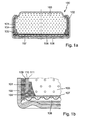
Fig. 1a zeigt eine Querschnittsdarstellung einer Ausführungsform einerKnopfzellen 100. Diese weistden Zellendeckel 101 auf, der als napfförmiges Gehäusehalbteil ausgebildet ist und gemäß dem oben beschriebenen Verfahren hergestellt wurde. Darüber hinaus umfasst sieals zum Zellendeckel 101 korrespondierendes Gehäusehalbteil den ebenfalls napfförmigen Zellenbecher 102. Diese bilden gemeinsam dasGehäuse der Knopfzelle 100.Im Zellendeckel 101ist eine Zinkpaste 103 als negative aktive Masse angeordnet. Diese ist frei von Quecksilber.Die Dichtung 104isoliert den Zellendeckel 101und den Zellenbecher 102 gegeneinander und dichtet gleichzeitig das Gehäuse nach außen ab. Sie umschließt dieSchnittkante 105 desZellendeckels 101. ImBodenbereich des Zellenbechers 102eine Gasdiffusionselektrode 106 angeordnet. Diese istdurch den Separator 107von der Zinkpaste 103 getrennt. Der Boden desZellenbechers 102 weist dieLufteintrittsöffnungen 108 auf. Bei der dargestellten Knopfzelle handelt es sich entsprechend um eine Zink/Luft-Knopfzelle. -
Fig. 1b zeigt einen vergrößerten Ausschnitt der inFig. 1a dargestellten Knopfzelle 100. Ausschnittsweise dargestellt sind derZellenbecher 102 und derZellendeckel 101 sowie dieDichtung 104, dieZinkpaste 103, dieGasdiffusionselektrode 106 und derSeparator 107.Der Zellendeckel 101 besteht aus einem Verbundmaterial umfassend eineLage Nickel 109, eineLage Stahl 110 und eineLage 111 umfassend Kupfer und einer Kupfer-Zinn-Legierung. Die einzelnen Lagen sind lediglich in der vergrößerten Darstellung dargestellt.
-
Fig. 1a shows a cross-sectional view of an embodiment of abutton cell 100. This has the cell cover 101st which is formed as a cup-shaped Gehäusehalbteil and prepared according to the method described above. In addition, it comprises as acell cover 101 corresponding Gehäusehalbteil the also cup-shapedcell cup 102. These together form the housing of thebutton cell 100. In thecell cover 101 , azinc paste 103 is arranged as a negative active mass. This is free of mercury. Thegasket 104 isolates thecell lid 101 and thecell cup 102 from each other and at the same time seals the case to the outside. It surrounds thecutting edge 105 of thecell lid 101. Agas diffusion electrode 106 is arranged in the bottom area of thecell cup 102 . This is separated from thezinc paste 103 by theseparator 107 . The bottom of thecell cup 102 has theair inlet openings 108 . The button cell shown is accordingly a zinc / air button cell. -
Fig. 1b shows an enlarged section of the inFig. 1a button cell 100. Neck manner shown thecell cup 102 and thecell cover 101 and theseal 104, thezinc paste 103, thegas diffusion electrode 106 and theseparator 107 are shown Thecell cover 101 is made of a composite material comprising a layer ofnickel 109, a layer ofsteel 110 and aLayer 111 comprising copper and a copper-tin alloy. The individual layers are shown only in the enlarged view.
Die Lage 111 mit Kupfer und der Kupfer-Zinn-Legierung bildet die Innenseite des Zellendeckels 101 und steht in direktem Kontakt mit der Zinkpaste 103. Die Lage 109 aus Nickel bildet die Außenseite des Zellendeckels.The
Hergestellt wurde der Zellendeckel 101 aus einem kupferseitig mit einer Zusatzschicht aus Zinn versehenen Trimetall. Nach dem Ausstanzen des Zellendeckels 101 aus diesem Material wurde dieser über zwei Stunden auf eine Temperatur von ca. 200 °C erwärmt. Dabei bildete sich aus der Kupferseite des Trimetalls und der darauf angeordneten Zusatzschicht aus Zinn die Lage 111 umfassend Kupfer und die Kupfer-Zinn-Legierung. Durch Diffusion bildete sich innerhalb der entstehenden (gemeinsamen) Lage 111 ein Konzentrationsgefälle. Es wurde festgestellt, dass innerhalb der Lage 111 Kupfer zur Lage aus Stahl hin angereichert ist. Zum Napfinneren hin steigt dagegen die Konzentration an Zinn. Unmittelbar an der Grenze zwischen der Lage 110 und der Lage 111 war sogar noch unlegiertes Kupfer zu finden. So begründet sich auch die Verwendung des Ausdrucks Lage 111 "umfassend Kupfer und aus einer Kupfer-Zinn-Legierung" Die Zinnschicht auf der Kupferseite des Trimetalls wies vor der Wärmebehandlung eine Dicke im Bereich zwischen 0,2 µm und 5 µm auf. Die Zinnschicht war galvanotechnisch auf dem Trimetall abgeschieden worden.The
Claims (2)
- A method for producing a bowl-shaped housing half-part provided with a copper alloy on the inside of a mercury-free button cell, comprising the steps:(1) providing a clad composite material with a layer of nickel, a layer of copper and an intermediate layer of steel or high-grade steel,(2) shaping of a bowl-shaped housing half-part made of the composite material, wherein the layer of nickel forms the outside and an additional layer forms the inside of the bowl-shaped housing half-part,
characterized in that
the composite material is provided, prior to step (2), on the copper side with the additional layer composed of at least one metal from the group consisting of tin, zinc, indium and bismuth or of an alloy composed of said metals, and the housing half-part, subsequent to step (2), is heat treated at a temperature between 200 °C and 400 °C, where the at least one metal from the group consisting of tin, zinc, indium and bismuth is alloyed with the copper of the copper layer. - The method according to claim 1, characterized in that the heat treatment is effected for a time period between 1 hour and 10 hours.
Applications Claiming Priority (2)
| Application Number | Priority Date | Filing Date | Title |
|---|---|---|---|
| DE102010062001A DE102010062001A1 (en) | 2010-11-25 | 2010-11-25 | Housing for mercury-free button cells |
| PCT/EP2011/070635 WO2012069449A1 (en) | 2010-11-25 | 2011-11-22 | Housing for mercury-free button cells |
Publications (2)
| Publication Number | Publication Date |
|---|---|
| EP2643868A1 EP2643868A1 (en) | 2013-10-02 |
| EP2643868B1 true EP2643868B1 (en) | 2015-07-22 |
Family
ID=45063113
Family Applications (1)
| Application Number | Title | Priority Date | Filing Date |
|---|---|---|---|
| EP11788797.6A Active EP2643868B1 (en) | 2010-11-25 | 2011-11-22 | Housing for mercury-free button cells |
Country Status (5)
| Country | Link |
|---|---|
| US (1) | US20130230763A1 (en) |
| EP (1) | EP2643868B1 (en) |
| CN (1) | CN103299449A (en) |
| DE (1) | DE102010062001A1 (en) |
| WO (1) | WO2012069449A1 (en) |
Families Citing this family (3)
| Publication number | Priority date | Publication date | Assignee | Title |
|---|---|---|---|---|
| CN103866359B (en) * | 2014-03-25 | 2016-04-06 | 湖南永盛新材料股份有限公司 | Mercury-free button cell negative electrode cover material and preparation method thereof |
| US10629859B2 (en) * | 2016-01-12 | 2020-04-21 | Panasonic Intellectual Property Management Co., Ltd. | Coin-shaped battery |
| CN110364645B (en) * | 2019-06-18 | 2022-10-18 | 深圳清华大学研究院 | Mercury-free button cell negative electrode cover material and preparation method and application thereof |
Family Cites Families (12)
| Publication number | Priority date | Publication date | Assignee | Title |
|---|---|---|---|---|
| JPS6161364A (en) | 1984-09-03 | 1986-03-29 | Matsushita Electric Ind Co Ltd | Alkaline battery |
| US5279905A (en) * | 1992-03-09 | 1994-01-18 | Eveready Battery Company, Inc. | Miniature zinc-air cell having an indium plated anode cupe |
| JPH0955194A (en) * | 1995-08-11 | 1997-02-25 | Seiko Instr Inc | Alkaline cell |
| US6447947B1 (en) * | 1999-12-13 | 2002-09-10 | The Gillette Company | Zinc/air cell |
| JP2001307739A (en) * | 2000-04-18 | 2001-11-02 | Sony Corp | Alkaline battery |
| US6830847B2 (en) * | 2001-04-10 | 2004-12-14 | The Gillette Company | Zinc/air cell |
| CN2514498Y (en) * | 2001-10-19 | 2002-10-02 | 何永基 | Non-mercury-alkaline button cell |
| JP4851708B2 (en) * | 2004-12-15 | 2012-01-11 | セイコーインスツル株式会社 | Alkaline battery and manufacturing method thereof |
| WO2006118791A1 (en) * | 2005-04-29 | 2006-11-09 | Eveready Battery Company, Inc. | Alkaline cell anode casing |
| CN100557869C (en) * | 2006-05-18 | 2009-11-04 | 中南大学 | Mercury-free alkaline button cell and manufacturing method thereof |
| JP5493229B2 (en) * | 2006-11-01 | 2014-05-14 | エバレデイ バツテリ カンパニー インコーポレーテツド | Alkaline electrochemical cell with reduced gas generation |
| DE102009017514A1 (en) * | 2009-04-04 | 2010-10-07 | Varta Microbattery Gmbh | Button cell without crimping |
-
2010
- 2010-11-25 DE DE102010062001A patent/DE102010062001A1/en not_active Withdrawn
-
2011
- 2011-11-22 WO PCT/EP2011/070635 patent/WO2012069449A1/en active Application Filing
- 2011-11-22 EP EP11788797.6A patent/EP2643868B1/en active Active
- 2011-11-22 CN CN2011800566042A patent/CN103299449A/en active Pending
- 2011-11-22 US US13/885,528 patent/US20130230763A1/en not_active Abandoned
Also Published As
| Publication number | Publication date |
|---|---|
| CN103299449A (en) | 2013-09-11 |
| EP2643868A1 (en) | 2013-10-02 |
| DE102010062001A1 (en) | 2012-05-31 |
| US20130230763A1 (en) | 2013-09-05 |
| WO2012069449A1 (en) | 2012-05-31 |
Similar Documents
| Publication | Publication Date | Title |
|---|---|---|
| DE69311934T3 (en) | Mercury-free zinc-air miniature cell | |
| DE60216982T2 (en) | Zinc-air cell | |
| DE19647593B4 (en) | Method for producing a button cell | |
| DE60113836T2 (en) | AIR CELL WITHOUT MERCURY | |
| EP2110869B1 (en) | Galvanic element with innovative housing | |
| EP2230704A1 (en) | Button cell with coated outer surface | |
| DE2636230C2 (en) | Galvanic element, especially an alkaline accumulator | |
| EP2643868B1 (en) | Housing for mercury-free button cells | |
| EP2550695A1 (en) | Button cell protected against short-circuit | |
| EP2690687A1 (en) | Button cell with anode coil and method for its production | |
| WO2012022778A1 (en) | Metal-air cell having high capacity | |
| WO2011128059A1 (en) | Film conductor for flat cells and method for producing same | |
| DE10213686A1 (en) | Voltaic cell element comprises a cell lid having an outer surface coated with a nickel-free copper-tin alloy | |
| DE2657342B2 (en) | Dry element | |
| EP3520167B1 (en) | Zinc/air button cell | |
| EP0289705B1 (en) | Primary galvanic cell with alkaline electrolytes dischargeable at a high temperature | |
| CH656256A5 (en) | SILVER OXIDE CELLS. | |
| EP3547389A1 (en) | Method for producing a housing of a battery cell and corresponding housing and battery cell | |
| DE3133599A1 (en) | Galvanic element having metallic gas in the sealing region | |
| WO2014198450A1 (en) | Storage-stable gas production cell | |
| DE4031806C2 (en) | Galvanic element with negative zinc electrode | |
| EP1367665A1 (en) | Method for manufacturing of a rechargeable galvanic element with a negative lithium/indium electrode | |
| EP3683875A1 (en) | Electrochemical gas development cell, in particular mercury-free hydrogen development cell | |
| EP3742515A1 (en) | Button cell and method for the production of button cells | |
| DE202010016528U1 (en) | Electrochemical gas evolution cell, in particular mercury-free hydrogen evolution cell |
Legal Events
| Date | Code | Title | Description |
|---|---|---|---|
| PUAI | Public reference made under article 153(3) epc to a published international application that has entered the european phase |
Free format text: ORIGINAL CODE: 0009012 |
|
| 17P | Request for examination filed |
Effective date: 20130508 |
|
| AK | Designated contracting states |
Kind code of ref document: A1 Designated state(s): AL AT BE BG CH CY CZ DE DK EE ES FI FR GB GR HR HU IE IS IT LI LT LU LV MC MK MT NL NO PL PT RO RS SE SI SK SM TR |
|
| DAX | Request for extension of the european patent (deleted) | ||
| 17Q | First examination report despatched |
Effective date: 20140228 |
|
| GRAP | Despatch of communication of intention to grant a patent |
Free format text: ORIGINAL CODE: EPIDOSNIGR1 |
|
| RIC1 | Information provided on ipc code assigned before grant |
Ipc: H01M 2/02 20060101AFI20150408BHEP Ipc: H01M 6/04 20060101ALI20150408BHEP Ipc: H01M 12/06 20060101ALN20150408BHEP Ipc: H01M 2/04 20060101ALI20150408BHEP Ipc: H01M 6/12 20060101ALI20150408BHEP |
|
| INTG | Intention to grant announced |
Effective date: 20150422 |
|
| GRAS | Grant fee paid |
Free format text: ORIGINAL CODE: EPIDOSNIGR3 |
|
| GRAA | (expected) grant |
Free format text: ORIGINAL CODE: 0009210 |
|
| AK | Designated contracting states |
Kind code of ref document: B1 Designated state(s): AL AT BE BG CH CY CZ DE DK EE ES FI FR GB GR HR HU IE IS IT LI LT LU LV MC MK MT NL NO PL PT RO RS SE SI SK SM TR |
|
| REG | Reference to a national code |
Ref country code: GB Ref legal event code: FG4D Free format text: NOT ENGLISH |
|
| REG | Reference to a national code |
Ref country code: CH Ref legal event code: EP |
|
| REG | Reference to a national code |
Ref country code: IE Ref legal event code: FG4D Free format text: LANGUAGE OF EP DOCUMENT: GERMAN |
|
| REG | Reference to a national code |
Ref country code: AT Ref legal event code: REF Ref document number: 738341 Country of ref document: AT Kind code of ref document: T Effective date: 20150815 |
|
| REG | Reference to a national code |
Ref country code: DE Ref legal event code: R096 Ref document number: 502011007403 Country of ref document: DE |
|
| REG | Reference to a national code |
Ref country code: FR Ref legal event code: PLFP Year of fee payment: 5 |
|
| REG | Reference to a national code |
Ref country code: LT Ref legal event code: MG4D |
|
| REG | Reference to a national code |
Ref country code: NL Ref legal event code: MP Effective date: 20150722 |
|
| PG25 | Lapsed in a contracting state [announced via postgrant information from national office to epo] |
Ref country code: FI Free format text: LAPSE BECAUSE OF FAILURE TO SUBMIT A TRANSLATION OF THE DESCRIPTION OR TO PAY THE FEE WITHIN THE PRESCRIBED TIME-LIMIT Effective date: 20150722 Ref country code: LT Free format text: LAPSE BECAUSE OF FAILURE TO SUBMIT A TRANSLATION OF THE DESCRIPTION OR TO PAY THE FEE WITHIN THE PRESCRIBED TIME-LIMIT Effective date: 20150722 Ref country code: NO Free format text: LAPSE BECAUSE OF FAILURE TO SUBMIT A TRANSLATION OF THE DESCRIPTION OR TO PAY THE FEE WITHIN THE PRESCRIBED TIME-LIMIT Effective date: 20151022 Ref country code: LV Free format text: LAPSE BECAUSE OF FAILURE TO SUBMIT A TRANSLATION OF THE DESCRIPTION OR TO PAY THE FEE WITHIN THE PRESCRIBED TIME-LIMIT Effective date: 20150722 Ref country code: GR Free format text: LAPSE BECAUSE OF FAILURE TO SUBMIT A TRANSLATION OF THE DESCRIPTION OR TO PAY THE FEE WITHIN THE PRESCRIBED TIME-LIMIT Effective date: 20151023 |
|
| REG | Reference to a national code |
Ref country code: DE Ref legal event code: R082 Ref document number: 502011007403 Country of ref document: DE Representative=s name: OSTERTAG & PARTNER, PATENTANWAELTE MBB, DE Ref country code: DE Ref legal event code: R082 Ref document number: 502011007403 Country of ref document: DE Representative=s name: PATENTANWALTSKANZLEI CARTAGENA PARTNERSCHAFTSG, DE |
|
| PG25 | Lapsed in a contracting state [announced via postgrant information from national office to epo] |
Ref country code: HR Free format text: LAPSE BECAUSE OF FAILURE TO SUBMIT A TRANSLATION OF THE DESCRIPTION OR TO PAY THE FEE WITHIN THE PRESCRIBED TIME-LIMIT Effective date: 20150722 Ref country code: PT Free format text: LAPSE BECAUSE OF FAILURE TO SUBMIT A TRANSLATION OF THE DESCRIPTION OR TO PAY THE FEE WITHIN THE PRESCRIBED TIME-LIMIT Effective date: 20151123 Ref country code: IS Free format text: LAPSE BECAUSE OF FAILURE TO SUBMIT A TRANSLATION OF THE DESCRIPTION OR TO PAY THE FEE WITHIN THE PRESCRIBED TIME-LIMIT Effective date: 20151122 Ref country code: ES Free format text: LAPSE BECAUSE OF FAILURE TO SUBMIT A TRANSLATION OF THE DESCRIPTION OR TO PAY THE FEE WITHIN THE PRESCRIBED TIME-LIMIT Effective date: 20150722 Ref country code: SE Free format text: LAPSE BECAUSE OF FAILURE TO SUBMIT A TRANSLATION OF THE DESCRIPTION OR TO PAY THE FEE WITHIN THE PRESCRIBED TIME-LIMIT Effective date: 20150722 Ref country code: RS Free format text: LAPSE BECAUSE OF FAILURE TO SUBMIT A TRANSLATION OF THE DESCRIPTION OR TO PAY THE FEE WITHIN THE PRESCRIBED TIME-LIMIT Effective date: 20150722 Ref country code: PL Free format text: LAPSE BECAUSE OF FAILURE TO SUBMIT A TRANSLATION OF THE DESCRIPTION OR TO PAY THE FEE WITHIN THE PRESCRIBED TIME-LIMIT Effective date: 20150722 |
|
| REG | Reference to a national code |
Ref country code: DE Ref legal event code: R097 Ref document number: 502011007403 Country of ref document: DE |
|
| PG25 | Lapsed in a contracting state [announced via postgrant information from national office to epo] |
Ref country code: EE Free format text: LAPSE BECAUSE OF FAILURE TO SUBMIT A TRANSLATION OF THE DESCRIPTION OR TO PAY THE FEE WITHIN THE PRESCRIBED TIME-LIMIT Effective date: 20150722 Ref country code: IT Free format text: LAPSE BECAUSE OF FAILURE TO SUBMIT A TRANSLATION OF THE DESCRIPTION OR TO PAY THE FEE WITHIN THE PRESCRIBED TIME-LIMIT Effective date: 20150722 Ref country code: CZ Free format text: LAPSE BECAUSE OF FAILURE TO SUBMIT A TRANSLATION OF THE DESCRIPTION OR TO PAY THE FEE WITHIN THE PRESCRIBED TIME-LIMIT Effective date: 20150722 Ref country code: DK Free format text: LAPSE BECAUSE OF FAILURE TO SUBMIT A TRANSLATION OF THE DESCRIPTION OR TO PAY THE FEE WITHIN THE PRESCRIBED TIME-LIMIT Effective date: 20150722 Ref country code: SK Free format text: LAPSE BECAUSE OF FAILURE TO SUBMIT A TRANSLATION OF THE DESCRIPTION OR TO PAY THE FEE WITHIN THE PRESCRIBED TIME-LIMIT Effective date: 20150722 |
|
| PLBE | No opposition filed within time limit |
Free format text: ORIGINAL CODE: 0009261 |
|
| STAA | Information on the status of an ep patent application or granted ep patent |
Free format text: STATUS: NO OPPOSITION FILED WITHIN TIME LIMIT |
|
| PG25 | Lapsed in a contracting state [announced via postgrant information from national office to epo] |
Ref country code: RO Free format text: LAPSE BECAUSE OF FAILURE TO SUBMIT A TRANSLATION OF THE DESCRIPTION OR TO PAY THE FEE WITHIN THE PRESCRIBED TIME-LIMIT Effective date: 20150722 |
|
| 26N | No opposition filed |
Effective date: 20160425 |
|
| PG25 | Lapsed in a contracting state [announced via postgrant information from national office to epo] |
Ref country code: MC Free format text: LAPSE BECAUSE OF FAILURE TO SUBMIT A TRANSLATION OF THE DESCRIPTION OR TO PAY THE FEE WITHIN THE PRESCRIBED TIME-LIMIT Effective date: 20150722 Ref country code: LU Free format text: LAPSE BECAUSE OF FAILURE TO SUBMIT A TRANSLATION OF THE DESCRIPTION OR TO PAY THE FEE WITHIN THE PRESCRIBED TIME-LIMIT Effective date: 20151122 |
|
| REG | Reference to a national code |
Ref country code: CH Ref legal event code: PL |
|
| PG25 | Lapsed in a contracting state [announced via postgrant information from national office to epo] |
Ref country code: LI Free format text: LAPSE BECAUSE OF NON-PAYMENT OF DUE FEES Effective date: 20151130 Ref country code: CH Free format text: LAPSE BECAUSE OF NON-PAYMENT OF DUE FEES Effective date: 20151130 |
|
| REG | Reference to a national code |
Ref country code: IE Ref legal event code: MM4A |
|
| PG25 | Lapsed in a contracting state [announced via postgrant information from national office to epo] |
Ref country code: SI Free format text: LAPSE BECAUSE OF FAILURE TO SUBMIT A TRANSLATION OF THE DESCRIPTION OR TO PAY THE FEE WITHIN THE PRESCRIBED TIME-LIMIT Effective date: 20150722 |
|
| PG25 | Lapsed in a contracting state [announced via postgrant information from national office to epo] |
Ref country code: IE Free format text: LAPSE BECAUSE OF NON-PAYMENT OF DUE FEES Effective date: 20151122 |
|
| REG | Reference to a national code |
Ref country code: FR Ref legal event code: PLFP Year of fee payment: 6 |
|
| PG25 | Lapsed in a contracting state [announced via postgrant information from national office to epo] |
Ref country code: HU Free format text: LAPSE BECAUSE OF FAILURE TO SUBMIT A TRANSLATION OF THE DESCRIPTION OR TO PAY THE FEE WITHIN THE PRESCRIBED TIME-LIMIT; INVALID AB INITIO Effective date: 20111122 Ref country code: BG Free format text: LAPSE BECAUSE OF FAILURE TO SUBMIT A TRANSLATION OF THE DESCRIPTION OR TO PAY THE FEE WITHIN THE PRESCRIBED TIME-LIMIT Effective date: 20150722 Ref country code: SM Free format text: LAPSE BECAUSE OF FAILURE TO SUBMIT A TRANSLATION OF THE DESCRIPTION OR TO PAY THE FEE WITHIN THE PRESCRIBED TIME-LIMIT Effective date: 20150722 |
|
| PG25 | Lapsed in a contracting state [announced via postgrant information from national office to epo] |
Ref country code: CY Free format text: LAPSE BECAUSE OF FAILURE TO SUBMIT A TRANSLATION OF THE DESCRIPTION OR TO PAY THE FEE WITHIN THE PRESCRIBED TIME-LIMIT Effective date: 20150722 Ref country code: NL Free format text: LAPSE BECAUSE OF FAILURE TO SUBMIT A TRANSLATION OF THE DESCRIPTION OR TO PAY THE FEE WITHIN THE PRESCRIBED TIME-LIMIT Effective date: 20150722 |
|
| PG25 | Lapsed in a contracting state [announced via postgrant information from national office to epo] |
Ref country code: BE Free format text: LAPSE BECAUSE OF NON-PAYMENT OF DUE FEES Effective date: 20151130 |
|
| PG25 | Lapsed in a contracting state [announced via postgrant information from national office to epo] |
Ref country code: MT Free format text: LAPSE BECAUSE OF FAILURE TO SUBMIT A TRANSLATION OF THE DESCRIPTION OR TO PAY THE FEE WITHIN THE PRESCRIBED TIME-LIMIT Effective date: 20150722 |
|
| REG | Reference to a national code |
Ref country code: FR Ref legal event code: PLFP Year of fee payment: 7 |
|
| REG | Reference to a national code |
Ref country code: AT Ref legal event code: MM01 Ref document number: 738341 Country of ref document: AT Kind code of ref document: T Effective date: 20161122 |
|
| PG25 | Lapsed in a contracting state [announced via postgrant information from national office to epo] |
Ref country code: AT Free format text: LAPSE BECAUSE OF NON-PAYMENT OF DUE FEES Effective date: 20161122 |
|
| PG25 | Lapsed in a contracting state [announced via postgrant information from national office to epo] |
Ref country code: TR Free format text: LAPSE BECAUSE OF FAILURE TO SUBMIT A TRANSLATION OF THE DESCRIPTION OR TO PAY THE FEE WITHIN THE PRESCRIBED TIME-LIMIT Effective date: 20150722 Ref country code: MK Free format text: LAPSE BECAUSE OF FAILURE TO SUBMIT A TRANSLATION OF THE DESCRIPTION OR TO PAY THE FEE WITHIN THE PRESCRIBED TIME-LIMIT Effective date: 20150722 |
|
| PG25 | Lapsed in a contracting state [announced via postgrant information from national office to epo] |
Ref country code: AL Free format text: LAPSE BECAUSE OF FAILURE TO SUBMIT A TRANSLATION OF THE DESCRIPTION OR TO PAY THE FEE WITHIN THE PRESCRIBED TIME-LIMIT Effective date: 20150722 |
|
| REG | Reference to a national code |
Ref country code: DE Ref legal event code: R079 Ref document number: 502011007403 Country of ref document: DE Free format text: PREVIOUS MAIN CLASS: H01M0002020000 Ipc: H01M0050100000 |
|
| REG | Reference to a national code |
Ref country code: DE Ref legal event code: R082 Ref document number: 502011007403 Country of ref document: DE Representative=s name: OSTERTAG & PARTNER, PATENTANWAELTE MBB, DE |
|
| P01 | Opt-out of the competence of the unified patent court (upc) registered |
Effective date: 20230526 |
|
| PGFP | Annual fee paid to national office [announced via postgrant information from national office to epo] |
Ref country code: GB Payment date: 20231123 Year of fee payment: 13 |
|
| PGFP | Annual fee paid to national office [announced via postgrant information from national office to epo] |
Ref country code: FR Payment date: 20231123 Year of fee payment: 13 Ref country code: DE Payment date: 20231122 Year of fee payment: 13 |