EP2643554B1 - Beschaufelte plattenanordnung - Google Patents
Beschaufelte plattenanordnung Download PDFInfo
- Publication number
- EP2643554B1 EP2643554B1 EP11847184.6A EP11847184A EP2643554B1 EP 2643554 B1 EP2643554 B1 EP 2643554B1 EP 11847184 A EP11847184 A EP 11847184A EP 2643554 B1 EP2643554 B1 EP 2643554B1
- Authority
- EP
- European Patent Office
- Prior art keywords
- axis
- blade
- disk
- along
- retaining
- Prior art date
- Legal status (The legal status is an assumption and is not a legal conclusion. Google has not performed a legal analysis and makes no representation as to the accuracy of the status listed.)
- Not-in-force
Links
- 238000000034 method Methods 0.000 claims description 3
- 239000012530 fluid Substances 0.000 description 10
- 239000000567 combustion gas Substances 0.000 description 3
- 239000002131 composite material Substances 0.000 description 3
- 239000007789 gas Substances 0.000 description 3
- 239000000463 material Substances 0.000 description 3
- 239000000446 fuel Substances 0.000 description 2
- 239000002184 metal Substances 0.000 description 2
- 230000000284 resting effect Effects 0.000 description 2
- 239000011153 ceramic matrix composite Substances 0.000 description 1
- 238000002485 combustion reaction Methods 0.000 description 1
- 238000005242 forging Methods 0.000 description 1
- 238000007689 inspection Methods 0.000 description 1
- 230000014759 maintenance of location Effects 0.000 description 1
- 230000013011 mating Effects 0.000 description 1
- 239000011159 matrix material Substances 0.000 description 1
- 238000012986 modification Methods 0.000 description 1
- 230000004048 modification Effects 0.000 description 1
- 238000010248 power generation Methods 0.000 description 1
- 238000007789 sealing Methods 0.000 description 1
- 238000000926 separation method Methods 0.000 description 1
- 239000013589 supplement Substances 0.000 description 1
- 238000011144 upstream manufacturing Methods 0.000 description 1
Images


Classifications
-
- F—MECHANICAL ENGINEERING; LIGHTING; HEATING; WEAPONS; BLASTING
- F01—MACHINES OR ENGINES IN GENERAL; ENGINE PLANTS IN GENERAL; STEAM ENGINES
- F01D—NON-POSITIVE DISPLACEMENT MACHINES OR ENGINES, e.g. STEAM TURBINES
- F01D5/00—Blades; Blade-carrying members; Heating, heat-insulating, cooling or antivibration means on the blades or the members
- F01D5/30—Fixing blades to rotors; Blade roots ; Blade spacers
- F01D5/32—Locking, e.g. by final locking blades or keys
- F01D5/326—Locking of axial insertion type blades by other means
-
- F—MECHANICAL ENGINEERING; LIGHTING; HEATING; WEAPONS; BLASTING
- F01—MACHINES OR ENGINES IN GENERAL; ENGINE PLANTS IN GENERAL; STEAM ENGINES
- F01D—NON-POSITIVE DISPLACEMENT MACHINES OR ENGINES, e.g. STEAM TURBINES
- F01D11/00—Preventing or minimising internal leakage of working-fluid, e.g. between stages
- F01D11/005—Sealing means between non relatively rotating elements
- F01D11/006—Sealing the gap between rotor blades or blades and rotor
-
- F—MECHANICAL ENGINEERING; LIGHTING; HEATING; WEAPONS; BLASTING
- F01—MACHINES OR ENGINES IN GENERAL; ENGINE PLANTS IN GENERAL; STEAM ENGINES
- F01D—NON-POSITIVE DISPLACEMENT MACHINES OR ENGINES, e.g. STEAM TURBINES
- F01D5/00—Blades; Blade-carrying members; Heating, heat-insulating, cooling or antivibration means on the blades or the members
- F01D5/30—Fixing blades to rotors; Blade roots ; Blade spacers
- F01D5/3007—Fixing blades to rotors; Blade roots ; Blade spacers of axial insertion type
- F01D5/3015—Fixing blades to rotors; Blade roots ; Blade spacers of axial insertion type with side plates
-
- F—MECHANICAL ENGINEERING; LIGHTING; HEATING; WEAPONS; BLASTING
- F05—INDEXING SCHEMES RELATING TO ENGINES OR PUMPS IN VARIOUS SUBCLASSES OF CLASSES F01-F04
- F05D—INDEXING SCHEME FOR ASPECTS RELATING TO NON-POSITIVE-DISPLACEMENT MACHINES OR ENGINES, GAS-TURBINES OR JET-PROPULSION PLANTS
- F05D2230/00—Manufacture
- F05D2230/60—Assembly methods
-
- F—MECHANICAL ENGINEERING; LIGHTING; HEATING; WEAPONS; BLASTING
- F05—INDEXING SCHEMES RELATING TO ENGINES OR PUMPS IN VARIOUS SUBCLASSES OF CLASSES F01-F04
- F05D—INDEXING SCHEME FOR ASPECTS RELATING TO NON-POSITIVE-DISPLACEMENT MACHINES OR ENGINES, GAS-TURBINES OR JET-PROPULSION PLANTS
- F05D2230/00—Manufacture
- F05D2230/70—Disassembly methods
-
- F—MECHANICAL ENGINEERING; LIGHTING; HEATING; WEAPONS; BLASTING
- F05—INDEXING SCHEMES RELATING TO ENGINES OR PUMPS IN VARIOUS SUBCLASSES OF CLASSES F01-F04
- F05D—INDEXING SCHEME FOR ASPECTS RELATING TO NON-POSITIVE-DISPLACEMENT MACHINES OR ENGINES, GAS-TURBINES OR JET-PROPULSION PLANTS
- F05D2260/00—Function
- F05D2260/30—Retaining components in desired mutual position
- F05D2260/38—Retaining components in desired mutual position by a spring, i.e. spring loaded or biased towards a certain position
-
- Y—GENERAL TAGGING OF NEW TECHNOLOGICAL DEVELOPMENTS; GENERAL TAGGING OF CROSS-SECTIONAL TECHNOLOGIES SPANNING OVER SEVERAL SECTIONS OF THE IPC; TECHNICAL SUBJECTS COVERED BY FORMER USPC CROSS-REFERENCE ART COLLECTIONS [XRACs] AND DIGESTS
- Y02—TECHNOLOGIES OR APPLICATIONS FOR MITIGATION OR ADAPTATION AGAINST CLIMATE CHANGE
- Y02T—CLIMATE CHANGE MITIGATION TECHNOLOGIES RELATED TO TRANSPORTATION
- Y02T50/00—Aeronautics or air transport
- Y02T50/60—Efficient propulsion technologies, e.g. for aircraft
-
- Y—GENERAL TAGGING OF NEW TECHNOLOGICAL DEVELOPMENTS; GENERAL TAGGING OF CROSS-SECTIONAL TECHNOLOGIES SPANNING OVER SEVERAL SECTIONS OF THE IPC; TECHNICAL SUBJECTS COVERED BY FORMER USPC CROSS-REFERENCE ART COLLECTIONS [XRACs] AND DIGESTS
- Y10—TECHNICAL SUBJECTS COVERED BY FORMER USPC
- Y10T—TECHNICAL SUBJECTS COVERED BY FORMER US CLASSIFICATION
- Y10T29/00—Metal working
- Y10T29/49—Method of mechanical manufacture
- Y10T29/49316—Impeller making
- Y10T29/4932—Turbomachine making
- Y10T29/49321—Assembling individual fluid flow interacting members, e.g., blades, vanes, buckets, on rotary support member
Definitions
- the invention relates to a bladed disk assembly wherein one or more blades are mounted to a disk for concurrent rotation with the disk.
- U.S. Pat. No. 4,108,571 discloses a bladed rotor assembly for a gas turbine engine.
- a bladed rotor assembly for a gas turbine comprises blades whose roots are held in slots in a blade carrying member.
- locking members engage with the blades and the member.
- At least one of the engagements comprises a projection defining an undercut into which an edge of the locking member engages.
- the edge and the undercut are shaped to form a groove which tapers so that its section reduces in the radially outward direction, and a wedging member is mounted in the groove so that it tends to centrifuge outward in the groove and wedge the edge in the undercut against a wall of the undercut.
- Document DE 10 2008 013 118 A1 discloses an assembly for mounting a turbine blade to a turbine disk corresponding to the preamble of claim 1, in which turbine disk a profile groove having a profiled cross section is provided, which runs in parallel to the rotation axis of the turbine disk.
- the fastening part is fitted to a first protrusion of a rest groove by a longitudinal edge of a first flat side, while a nose is simultaneously fitted to a securing groove, which is formed on a lower side of a part of a foot of the turbine blade protruding from the profile groove.
- Document EP 1 584 794 A1 describes a device for axially supporting blades on a disk of a rotor of a turbo-machine.
- the device comprises an upstream annulus and a downstream annulus mounted by a radially inner edge in an annular groove of the disk and resting against feet of the blades mounted in grooves of a periphery of the disk.
- a circular lock held in the annular groove keeps the downstream annulus from rotating in the annular groove.
- a bladed rotor for a high pressure compressor of a gas turbine engine which rotor comprises a disk carrying an annular array of aerofoil blades in axially extending fir tree root slots. Retention plates carried in radially inner and outer slots prevent axial movement of the blade roots in the slots.
- the invention is a bladed disk assembly according to claim 1 and a method according to claim 12.
- Embodiments of the invention can be especially desirable for use with composite blades, organic matrix composite or ceramic matrix composite. However, it is noted that the invention is not limited to use with composite blades.
- Embodiments of the invention can replace smash plates. Smash plates are installed by placing the edges of a sheet metal component in a lip/groove feature on the disk and a similar, corresponding feature on the blades. The final segment of the plate is installed and then smashed in place to prevent the plates from popping out. Smash plates can cause damage to blades. Also, the use of smash plates requires forming the blade with a groove; this groove can be difficult to produce and can be a location for high stress concentration in the blade. Thus, embodiments of the invention can eliminate the need for applying any deforming force on the blades while retaining the components and also providing a sealing function.
- any benefits articulated herein may not be realized in all operating environments for all embodiments of the invention. Furthermore, it is noted that the benefits articulated herein are not exhaustive, other benefits may be perceived in the practice of the exemplary embodiment or in the practice of alternative embodiments of the invention. The benefits associated with the exemplary embodiments and described herein are not limitations of the broader invention, but rather demonstrate industrial applicability of the invention through the exemplary embodiments.
- FIG. 1 schematically shows a turbine engine 10.
- the various unnumbered arrows represent the flow of fluid through the turbine engine 10.
- the turbine engine 10 can produce power for several different kinds of applications, including vehicle propulsion and power generation, among others.
- the exemplary embodiments of the invention disclosed herein, as well as other embodiments of the broader invention can be practiced in any configuration of turbine engine and in any application other than turbine engines in which inspection of difficult to access components is desired or required.
- the exemplary turbine engine 10 can include an inlet 12 to receive fluid such as air.
- the turbine engine 10 can include a fan to direct fluid into the inlet 12 in alternative embodiments of the invention.
- the turbine engine 10 can also include a compressor section 14 to receive the fluid from the inlet 12 and compress the fluid.
- the compressor section 14 can be spaced from the inlet 12 along a centerline axis 16 of the turbine engine 10.
- the turbine engine 10 can also include a combustor section 18 to receive the compressed fluid from the compressor section 14.
- the compressed fluid can be mixed with fuel from a fuel system 20 and ignited in an annular combustion chamber 22 defined by the combustor section 18.
- the turbine engine 10 can also include a turbine section 24 to receive the combustion gases from the combustor section 18.
- the energy associated with the combustion gases can be converted into kinetic energy (motion) in the turbine section 24.
- shafts 26, 28 are shown disposed for rotation about the centerline axis 16 of the turbine engine 10.
- Alternative embodiments of the invention can include any number of shafts.
- the shafts 26, 28 can be journaled together for relative rotation.
- the shaft 26 can be a low pressure shaft supporting compressor blades 30 of a low pressure portion of the compressor section 14.
- the compressor blades, such as blade 30, can be part of a bladed disk assembly 48 fixed for rotation with the shaft 26.
- the blade disk assembly 48 is shown schematically in Figure 1 .
- the bladed disk assembly 48 can includes a disk or rotor 50 fixed to the shaft 26 for concurrent rotation.
- the disk 50 can include a plurality of grooves (not visible in Figure 1 ), each groove receiving a blade such as blade 30.
- a plurality of vanes 31 can be positioned to direct fluid downstream of the blades 30.
- the shaft 26 can also support low pressure turbine blades 32 of a low pressure portion of the turbine section 24.
- the shaft 28 encircles the shaft 26.
- the shafts 26, 28 can be journaled together, wherein bearings are disposed between the shafts 26, 28 to permit relative rotation.
- the shaft 28 can be a high pressure shaft supporting compressor blades 34 of a high pressure portion of the compressor section 14.
- the high pressure blades, such as blade 34 can be part of a bladed disk assembly such as described above with respect to the blade 30.
- a plurality of vanes 35 can be positioned to receive fluid from the blades 34.
- the shaft 28 can also support high pressure turbine blades 36 of a high pressure portion of the turbine section 24.
- a plurality of vanes 37 can be positioned to direct combustion gases over the blades 36.
- the compressor section 14 can define a multi-stage compressor, as shown schematically in Figure 1 .
- a "stage" of the compressor section 14 can be defined as a pair of axially adjacent blades and vanes.
- the vanes 31 and the blades 30 can define a first stage of the compressor section 14.
- the vanes 35 and the blades 34 can define a second stage of the compressor section 14.
- the invention can be practiced with a compressor having any number of stages.
- a casing 38 defines a first wall and can be positioned to surround at least some of the components of the turbine engine 10.
- the exemplary casing 38 can encircle the compressor section 14, the combustor section 18, and the turbine section 24. In alternative embodiments of the invention, the casing 38 may encircle less than all of the compressor section 14, the combustor section 18, and the turbine section 24.
- Figure 1 shows the turbine engine 10 having a fan 40 positioned forward of the compressor section 14 along the centerline axis 16.
- the fan 40 can include a plurality of blades 42 extending radially outward from a hub 44.
- the fan 40 can be encircled by a fan case 46.
- the fan case 46 can be fixed to the casing 38.
- the casing 38 is shown schematically as being a single structure. In some embodiments of the invention, the casing 38 can be a single structure. In other embodiments of the invention, the casing 38 can be formed from a plurality of members that are fixed together. The forward-most member can be designated as a "front frame.”
- the fan case 46 can be mounted to a front frame portion of the casing 38.
- the blade 30 can be part of a bladed disk assembly 48.
- an exemplary bladed disk assembly 48 is shown in Figure 2 , a detailed perspective view with a portion cut-away.
- Figure 3 shows a planar view of the cross-section shown in Figure 2 .
- the bladed disk assembly 48 includes a disk 50 centered on an axis, such as the axis 16 shown in Figure 1 .
- the disk 50 has a plurality of grooves extending along the axis, or at some skewed angle relative to the axis, such as the groove 52.
- the grooves are shaped similarly and extend parallel to one another, or at consistent angles to the assembly centerline axis.
- a blade, such as blade 30, is received in the groove 52.
- the bladed disk assembly 48 also includes a retaining clip 54 to limit movement of the blade 30 along the axis 16.
- the retaining clip 54 contacts the blade 30.
- the retaining clip 54 is engaged with the disk 50 through a snap-fit.
- a snap-fit is self-locking joint whose mating parts exert a cam action during assembly, wherein at least one of the parts is elastically deformed until slipping past a raised lip on the other part. The first part elastically recovers after passing the raised lip of the other part and thereby prevents separation of the parts.
- the retaining clip 54 is operable to elastically deform during engagement with the disk 50.
- the exemplary retaining clip 54 includes a disc portion 56 that is at least partially arcuate and centered on the axis 16.
- the exemplary disc portion 56 is fully arcuate or circular, but embodiments of the invention can be practiced differently.
- a plurality of partially-arcuate disc portions 56 can be positioned circumferentially adjacent to one another about an axis.
- the retaining clip 54 can extend radially outward relative to the axis 16 from an inner end 58 to an outer end 60.
- the disc portion 56 can be the portion of the retaining clip 54 proximate to the outer end 60 and can contact the blade 30 to limit movement of the blade 30 along the axis 16. This is best shown in Figure 3 .
- the exemplary retaining clip 54 also includes a retaining portion 62.
- the retaining portion 62 extends a length along the axis 16, referenced at 64 in Figure 3 . The distance of the retaining portion 62 from the axis 16 varies along the length 64.
- the retaining portion 62 is a first distance from the axis 16.
- the axis 16 would be below the edge of the paper in Figure 3 .
- the retaining portion 62 is a second distance from the axis 16 greater than the first distance.
- the retaining portion 62 is a third distance from the axis 16 less than the second distance.
- Part of the disk 50, referenced at 72, is positioned directly between the first position 66 and the third position 70 along the axis 16. The retaining portion 62 can thus wrap around part 72 of the disk 50.
- the retaining portion 62 can be integrally-formed and unitary with the disc portion 56, as shown in Figures 2 and 3 .
- the retaining clip 54 can be a stamped, sheet metal structure and take numerous forms in various embodiments of the invention.
- the retaining clip 54 may be machined from forging, bar or plate stock, or cast material.
- Figures 2 and 3 show an embodiment in which the retaining portion 62 overlaps itself along the length 64.
- the section of the retaining portion 62 extending between points referenced at 68 and 74 can be elastically deformed during assembly to enhance the snap-lock defined between retaining portion 62 (at positions 66, 68, 70) and the part 72.
- the section between positions 68 and 74 can be spring-like and bias the retaining clip 54 against the part 72.
- the inner end 58 can be used as a "pull tab" for the removal of the retaining clip 54.
- a tool such as a pair of pliers
- FIG 4 shows an alternative embodiment of the invention.
- a bladed disk assembly 48a includes a disk 50a centered on an axis, such as the axis 16 shown in Figure 1 .
- the disk 50a has a plurality of grooves extending along the axis 16, such as the groove 52a.
- a blade, such as blade 30a, is received in the groove 52a.
- the bottom of the blade 30a is referenced at 78a.
- the bladed disk assembly 48a also includes a retaining clip 54a to limit movement of the blade 30a along the axis 16.
- the retaining clip 54a contacts the blade 30a.
- the retaining clip 54a is engaged with the disk 50a through a snap-fit.
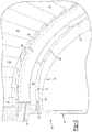
- Figure 4 shows that a retaining clip according to an embodiment of the invention need not overlap itself along the axis 16 (as shown in the first embodiment) and can snap onto a part 72a of the disk 50a facing radially inwardly.
- the part 72 shown in Figure 3 faces radially outwardly.
- FIG. 5 shows another alternative embodiment of the invention.
- a bladed disk assembly 48b includes a disk 50b centered on an axis, such as the axis 16 shown in Figure 1 .
- the disk 50b has a plurality of grooves extending along the axis 16, such as the groove 52b.
- a blade, such as blade 30b, is received in the groove 52b.
- the bottom of the blade 30b is referenced at 78b.
- the bladed disk assembly 48b also includes a retaining clip 54b to limit movement of the blade 30b along the axis 16.
- the retaining clip 54b contacts the blade 30b.
- the retaining clip 54b is engaged with the disk 50b through a snap-fit.
- the exemplary retaining clip 54b can engage part 72b of the disk 50b in a snap-fit.
- Figure 5 shows that the disc portion 56b bows along the axis, away from the disk 50b.
- the fluid pressure can act on the disc portion 56b and partially or fully flatten the disc portion 56b.
- the surface of the disc portion 56b facing away from the disk 50b can thus define a pressure face.
- a seal between the retaining portion 54b and the disk 50b can be enhanced.
- a radially outer end 60b of the retaining clip 54b can be urged radially outward.
- the retaining clip 54b can define a radially sliding contact engaging the blade 30, referenced at 80b.
- the sliding contact 80b can be at least partially arcuate, like a runner of a sled, in a cross-section including the axis 16, such as shown in Figure 5 .
- the snap-fit defined between the retaining clip 54b and the part 72b can limit radially inward movement of the disc portion 56b.
- the engagement between a position of the retaining clip 54b referenced at 82b and the part 72b provides a hard stop against radially inward movement of the retaining clip 54b.
- the shape of the retaining clip 54b itself will limit radially inward movement of the disc portion 56b in response to pressure acting on the pressure face.
- deformation of the pressure face could more easily cause the retaining portion 62b to move radially inward.
- the engagement between the retaining portion 62b and the disk 50b defines an anchor point resisting this radially inward movement.
- the snap-fit between the retaining clip 54b and the disk 50b is thus such that the snap-fit limits movement of the retaining clip 54b radially and axially relative to the axis 16.
- FIG 6 shows an alternative embodiment of the invention.
- a bladed disk assembly 48c includes a disk 50c centered on an axis, such as the axis 16 shown in Figure 1 .
- the disk 50c has a plurality of grooves extending along the axis 16, such as the groove 52c.
- a blade, such as blade 30c, is received in the groove 52c.
- the bottom of the blade 30c is referenced at 78c.
- the bladed disk assembly 48c also includes a retaining clip 54c to limit movement of the blade 30c along the axis 16.
- the retaining clip 54c contacts the blade 30c.
- the retaining clip 54c is engaged with the disk 50c through a snap-fit.
- the exemplary retaining clip 54c can engage a part 72c of the disk 50c in a snap-fit.
- a retaining portion 62c of the retaining clip 54c is a first distance from the axis 16.
- the retaining portion 62c is a second distance from the axis 16 less than the first distance.
- the retaining portion 62c is a third distance from the axis 16 less than the second distance. The part 72c is thus positioned directly, radially between the first position 66c and the third position 72c relative to the axis 16.
- Figure 6 also shows that embodiments of the invention can include a separate seal.
- a seal member 84c can be positioned between the retaining clip 54c and the blade 30c, radially inward of a sliding contact 80c.
- a circular seal member 84c is shown for illustrative purposes.
- a seal member included as part of an embodiment of the invention can take any shape and can be formed from any material appropriate in view of the operating environment.
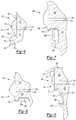
- a bladed disk assembly 48d includes a disk 50d having a plurality of grooves extending along the axis 16, such as the groove 52d.
- a blade such as blade 30d, is received in the groove 52d.
- the bottom of the blade 30d is referenced at 78d.
- the bladed disk assembly 48d also includes a retaining clip 54d to limit movement of the blade 30d along the axis 16.
- the retaining clip 54d contacts the blade 30d.
- the retaining clip 54d is engaged with the disk 50d through a snap-fit.
- the exemplary retaining clip 54d can engage a part 72d of the disk 50d in a snap-fit.
- a bladed disk assembly 48e includes a disk 50e having a plurality of grooves extending along the axis 16, such as the groove 52e.
- a blade such as blade 30e, is received in the groove 52e.
- the bottom of the blade 30e is referenced at 78e.
- the bladed disk assembly 48e also includes a retaining clip 54e to limit movement of the blade 30e along the axis 16.
- the retaining clip 54e contacts the blade 30e.
- the retaining clip 54e is engaged with the disk 50e through a snap-fit.
- the exemplary retaining clip 54e can engage a part 72e of the disk 50e in a snap-fit.
- Both of the embodiments shown in Figures 7 and 8 include retaining rings to limit movement of the respective retaining portions relative to the respective disk portions.
- retaining rings 86d and 88d are inserted along the axis.
- retaining rings 86e and 88e are inserted along the axis.
- the retaining rings could be replaced with a spiral-wound type snap ring for retaining the clip 54.
- the spiral-wound ring can have two winds in one ring, appearing as two separate structures in the cross section view.
- FIG 9 shows another embodiment of the invention.
- a bladed disk assembly 48f includes a disk 50f having a plurality of grooves extending along the axis 16, such as the groove 52f.
- a blade such as blade 30f, is received in the groove 52f.
- the bottom of the blade 30f is referenced at 78f.
- the bladed disk assembly 48f also includes a retaining clip 54f to limit movement of the blade 30f along the axis 16.
- the retaining clip 54f contacts the blade 30f.
- the retaining clip 54f is engaged with the disk 50f through a snap-fit.
- the exemplary retaining clip 54f can engage a part 72f of the disk 50f in a snap-fit.
- the radially-outer end 60f is curled and contacts a radially-inner side 90f of a platform 92f of the blade 30f.
- the radially-outer end 60f can bias the blade 30f radially outward. This will prevent the bottom 78f of the blade 30f from resting on the bottom of the groove 52c.
- the retaining clip 54 can be formed to define a plurality of circumferentially adjacent fingers.
- the exemplary retaining portion 62 is formed by the plurality of circumferentially adjacent fingers 94 extending radially inward from the disc portion 56.
- the exemplary fingers 94 can fit into an annular groove 96 defined by the disk 50.
- Figure 9 shows another embodiment in which the retaining clip 54f can include fingers 94f.
- a radially inward end 98f of the fingers 94f can connect to the disk 50 through a second snap-fit connection.
- the radially inward end 98f can be connected to a part 100f of the disk 50f as the finger 94f is received in the groove 96f.
- the inner end 98f can be used as a "pull tab" for the removal of the retaining clip 54f.
- a tool such as a pair of pliers
- the spring portion of the clip 54f is deformed radially outward such that the detent feature can be lifted over feature 100f and then the lifted under the feature 72f.
Landscapes
- Engineering & Computer Science (AREA)
- Mechanical Engineering (AREA)
- General Engineering & Computer Science (AREA)
- Structures Of Non-Positive Displacement Pumps (AREA)
Claims (13)
- Beschaufelte Scheibenanordnung (48; 48a; 48b; 48c; 48d; 48e; 48f) mit:einer auf eine Achse (16) zentrierten Scheibe (50; 50a; 50b; 50c; 50d; 50e; 50f), die mindestens eine sich entlang der Achse erstreckende Nut aufweist;einer in der Nut aufgenommenen Schaufel (30; 30a; 30b; 30c; 30d; 30e; 30f);einer Halteklammer (54; 54a; 54b; 54c; 54d; 54e; 54f), die die Schaufel kontaktiert, um eine Bewegung der Schaufel entlang der Achse zu begrenzen, wobei die Halteklammer einen elastisch deformierbaren Abschnitt aufweist, der über eine Rastverbindung mit einem Teil (72; 72a; 72b; 72c; 72d; 72e; 72f) der Scheibe (50; 50a; 50b; 50c; 50d; 50e; 50f) in Eingriff steht,wobei die Halteklammer umfasst:einen Scheibenabschnitt (56; 56b), der zumindest teilweise gebogen und auf die Achse zentriert ist, wobei sich der Scheibenabschnitt (56; 56b) radial relativ zur Achse von einem inneren Ende zu einem äußeren Ende erstreckt, wobei der Scheibenabschnitt (56; 56b) die Schaufel kontaktiert und die Bewegung der Schaufel entlang der Achse begrenzt; undeinen Halteabschnitt (62; 62b; 62c), der sich über eine Strecke längs der Achse erstreckt, wobei der Abstand des Halteabschnitts (62; 62b; 62c) von der Achse entlang der Strecke variiert, wobei der Halteabschnitt (62; 62b;62c) den elastisch deformierbaren Abschnitt bildet,dadurch gekennzeichnet, dass der Scheibenabschnitt (56; 56b) entlang der Achse von der Scheibe (50; 50a; 50b; 50c; 50d; 50e; 50f) weggebogen ist und dadurch einen radial gleitenden, an der Schaufel angreifenden Kontakt (80b; 80c) definiert, wobei der Scheibenabschnitt (56; 56b) dazu betriebsfähig ist, sich im Betrieb zu deformieren.
- Beschaufelte Scheibenanordnung nach Anspruch 1, wobei die Halteklammer dazu betriebsfähig ist, sich während eines Eingriffs mit der Scheibe (50; 50a; 50b; 50c; 50d; 50e; 50f) elastisch zu deformieren.
- Beschaufelte Scheibenanordnung nach Anspruch 1, wobei der Halteabschnitt (62; 62b; 62c) einstückig und einheitlich mit dem Scheibenabschnitt ausgebildet ist; oder
wobei sich der Halteabschnitt entlang der Strecke selbst überlappt; oder
wobei der Halteabschnitt an einer ersten Stelle (66) entlang der Strecke einen ersten Abstand von der Achse hat, der Halteabschnitt an einer zweiten Stelle (68) entlang der Strecke einen zweiten Abstand von der Achse hat, der geringer als der erste Abstand ist, der Halteabschnitt an einer dritten Stelle (70) entlang der Strecke einen dritten Abstand von der Achse hat, der größer als der zweite Abstand ist, und wobei der Teil (72; 72a; 72b; 72c; 72d; 72e; 72f) des Scheibenabschnitts längs der Achse unmittelbar zwischen der ersten Stelle (66) und der dritten Stelle (70) angeordnet ist. - Beschaufelte Scheibenanordnung nach Anspruch 1,
wobei der Halteabschnitt an einer ersten Stelle (66) entlang der Strecke einen ersten Abstand von der Achse hat, der Halteabschnitt an einer zweiten Stelle (68) entlang der Strecke einen zweiten Abstand von der Achse hat, der geringer als der erste Abstand ist, der Halteabschnitt an einer dritten Stelle (70) entlang der Strecke einen dritten Abstand von der Achse hat, der geringer als der zweite Abstand ist, und
wobei der Teil (72; 72a; 72b; 72c; 72d; 72e; 72f) des Scheibenabschnitts relativ zu der Achse radial unmittelbar zwischen der ersten Stelle (66) und der dritten Stelle (70) angeordnet ist. - Beschaufelte Scheibenanordnung nach Anspruch 1, wobei der den radial gleitenden Kontakt (80b; 80c) definierende Scheibenabschnitt in einem die Achse enthaltenden Querschnitt gekrümmt ist.
- Beschaufelte Scheibenanordnung nach Anspruch 1, wobei der Halteabschnitt (62; 62b; 62c) eine radial einwärts gerichtete Bewegung des Scheibenabschnitts (56; 56b) begrenzt.
- Beschaufelte Scheibenanordnung nach Anspruch 1, ferner umfassend
ein zwischen dem Scheibenabschnitt und der Schaufel radial einwärts des gleitenden Kontakts (80c) angeordnetes Dichtungselement (84c). - Beschaufelte Scheibenanordnung nach Anspruch 1, ferner umfassend
einen Sicherungsring (86d, 88d; 86e, 88e), der eine Bewegung der Halteklammer bezüglich der Scheibe (50; 50a; 50b; 50c; 50d; 50e; 50f) begrenzt. - Beschaufelte Scheibenanordnung nach Anspruch 1, wobei ein radial äußeres Ende (60f) der Halteklammer (54f) gewunden ist und eine radial innere Seite (90f) einer Plattform (92f) der Schaufel kontaktiert.
- Beschaufelte Scheibenanordnung nach Anspruch 1, wobei die Halteklammer ferner umfasst:
mehrere in Umfangsrichtung benachbarte Finger (94; 94f), die sich radial einwärts erstrecken und die in eine von der Scheibe definierte Ringnut (96) passen. - Beschaufelte Scheibenanordnung nach Anspruch 1, wobei die Halteklammer ferner umfasst:
zumindest eine Zuglasche (58; 98f) zum Entfernen der Halteklammer von der Scheibe. - Verfahren, mit den Schritten:Bilden mindestens einer Nut in einer auf eine Achse (16) zentrierten Scheibe (50; 50a; 50b; 50c; 50d; 50e; 50f), wobei die mindestens eine Nut entlang der Achse verläuft;Anordnen einer Schaufel (30; 30a; 30b; 30c; 30d; 30e; 30f) in der Nut; undKontaktieren der Schaufel mit einer Halteklammer (54; 54a; 54b; 54c; 54d; 54e; 54f), um eine Bewegung der Schaufel längs der Achse zu begrenzen, wobei die Halteklammer einen elastisch deformierbaren Abschnitt aufweist, der über eine Rastverbindung mit einem Teil (72; 72a; 72b; 72c; 72d; 72e; 72f) der Scheibe (50; 50a; 50b; 50c; 50d; 50e; 50f) in Eingriff steht;wobei die Halteklammer (54; 54a; 54b; 54c; 54d; 54e; 54f) umfasst:einen Scheibenabschnitt (56; 56b), der zumindest teilweise gebogen und auf die Achse zentriert ist, wobei sich der Scheibenabschnitt radial relativ zur Achse von einem inneren Ende zu einem äußeren Ende erstreckt, wobei der Scheibenabschnitt die Schaufel kontaktiert und die Bewegung der Schaufel längs der Achse begrenzt; undeinen Halteabschnitt (62; 62b; 62c), der sich über eine Strecke entlang der Achse erstreckt, wobei der Abstand des Halteabschnitts von der Achse entlang der Strecke variiert,gekennzeichnet durch den weiteren Schritt des Biegens des Scheibenabschnitts auswärts von der Schaufel entlang der Achse weg von der Scheibe, um dadurch einen radial gleitenden, an der Schaufel angreifenden Kontakt zu definieren, wobei der Scheibenabschnitt dazu betriebsfähig ist, sich im Betrieb zu deformieren.
- Verfahren nach Anspruch 12, ferner umfassend den Schritt des:Wickelns der Halteklammer (54; 54a; 54b; 54c; 54d; 54e; 54f) um den Teil (72; 72a; 72b; 72c; 72d; 72e; 72f) der Scheibe; oderAnordnen einer Dichtung (84c) zwischen der Halteklammer und der Schaufel; oderradial auswärts Vorspannen der Schaufel mittels der Halteklammer; oderFestlegen einer zweiten Rastverbindung zwischen der Halteklammer und der Scheibe.
Applications Claiming Priority (2)
| Application Number | Priority Date | Filing Date | Title |
|---|---|---|---|
| US12/954,206 US8753090B2 (en) | 2010-11-24 | 2010-11-24 | Bladed disk assembly |
| PCT/US2011/062087 WO2012078375A1 (en) | 2010-11-24 | 2011-11-23 | Bladed disk assembly |
Publications (3)
| Publication Number | Publication Date |
|---|---|
| EP2643554A1 EP2643554A1 (de) | 2013-10-02 |
| EP2643554A4 EP2643554A4 (de) | 2014-08-13 |
| EP2643554B1 true EP2643554B1 (de) | 2018-07-11 |
Family
ID=46064529
Family Applications (1)
| Application Number | Title | Priority Date | Filing Date |
|---|---|---|---|
| EP11847184.6A Not-in-force EP2643554B1 (de) | 2010-11-24 | 2011-11-23 | Beschaufelte plattenanordnung |
Country Status (4)
| Country | Link |
|---|---|
| US (1) | US8753090B2 (de) |
| EP (1) | EP2643554B1 (de) |
| CA (1) | CA2819026C (de) |
| WO (1) | WO2012078375A1 (de) |
Families Citing this family (10)
| Publication number | Priority date | Publication date | Assignee | Title |
|---|---|---|---|---|
| US8840375B2 (en) * | 2011-03-21 | 2014-09-23 | United Technologies Corporation | Component lock for a gas turbine engine |
| EP2959113B1 (de) | 2013-02-23 | 2018-10-31 | Rolls-Royce Corporation | Profildichtung für einen gasturbinen-keramikmatrixverbundwerkstoff |
| EP2961939B1 (de) * | 2013-02-27 | 2019-04-10 | United Technologies Corporation | Anordnung zur abdichtung eines spaltes zwischen komponenten eines turbinenmotors |
| US10100737B2 (en) * | 2013-05-16 | 2018-10-16 | Siemens Energy, Inc. | Impingement cooling arrangement having a snap-in plate |
| FR3020408B1 (fr) * | 2014-04-24 | 2018-04-06 | Safran Aircraft Engines | Ensemble rotatif pour turbomachine |
| EP3073052B1 (de) | 2015-02-17 | 2018-01-24 | Rolls-Royce Corporation | Bläserbaugruppe |
| GB2547906B (en) * | 2016-03-02 | 2019-07-03 | Rolls Royce Plc | A bladed rotor arrangement |
| US10563665B2 (en) | 2017-01-30 | 2020-02-18 | Rolls-Royce North American Technologies, Inc. | Turbomachine stage and method of making same |
| FR3082550B1 (fr) * | 2018-06-13 | 2021-05-14 | Safran Aircraft Engines | Ensemble de turbomachine |
| US11313240B2 (en) | 2020-02-05 | 2022-04-26 | Raytheon Technologies Corporation | Rounded radial snap configuration for a gas turbine engine cover plate |
Family Cites Families (26)
| Publication number | Priority date | Publication date | Assignee | Title |
|---|---|---|---|---|
| US2761648A (en) | 1951-09-18 | 1956-09-04 | A V Roe Canada Ltd | Rotor blade locking device |
| US2994507A (en) | 1959-01-23 | 1961-08-01 | Westinghouse Electric Corp | Blade locking structure |
| US3045329A (en) | 1959-07-30 | 1962-07-24 | Gen Electric | Method for assembling tongue-and-groove members with locking keys |
| US3039740A (en) | 1959-11-27 | 1962-06-19 | Gen Motors Corp | Blade retainer |
| GB1095830A (en) * | 1966-09-13 | 1967-12-20 | Rolls Royce | Bladed rotor for a fluid flow machine such as a gas turbine engine |
| US3501249A (en) | 1968-06-24 | 1970-03-17 | Westinghouse Electric Corp | Side plates for turbine blades |
| GB1291302A (en) * | 1970-03-14 | 1972-10-04 | Sec Dep For Defendence | Improvements in bladed rotor assemblies |
| GB1512882A (en) | 1976-02-11 | 1978-06-01 | Rolls Royce | Bladed rotor assembly for a gas turbine engine |
| US4171930A (en) * | 1977-12-28 | 1979-10-23 | General Electric Company | U-clip for boltless blade retainer |
| FR2419389A1 (fr) * | 1978-03-08 | 1979-10-05 | Snecma | Perfectionnements aux flasques de rotors de turbomachines |
| US4349318A (en) | 1980-01-04 | 1982-09-14 | Avco Corporation | Boltless blade retainer for a turbine wheel |
| US4507052A (en) | 1983-03-31 | 1985-03-26 | General Motors Corporation | End seal for turbine blade bases |
| US4523890A (en) * | 1983-10-19 | 1985-06-18 | General Motors Corporation | End seal for turbine blade base |
| GB9517369D0 (en) * | 1995-08-24 | 1995-10-25 | Rolls Royce Plc | Bladed rotor |
| US6109877A (en) | 1998-11-23 | 2000-08-29 | Pratt & Whitney Canada Corp. | Turbine blade-to-disk retention device |
| US6315298B1 (en) | 1999-11-22 | 2001-11-13 | United Technologies Corporation | Turbine disk and blade assembly seal |
| EP1124038A1 (de) | 2000-02-09 | 2001-08-16 | Siemens Aktiengesellschaft | Turbinenschaufelanordnung |
| US6533550B1 (en) | 2001-10-23 | 2003-03-18 | Pratt & Whitney Canada Corp. | Blade retention |
| JP3864157B2 (ja) * | 2003-12-05 | 2006-12-27 | 本田技研工業株式会社 | 軸流型タービンホイール |
| EP1584791A1 (de) | 2004-04-07 | 2005-10-12 | Siemens Aktiengesellschaft | Strömungsmaschine und Rotor für eine Strömungsmaschine |
| FR2868808B1 (fr) * | 2004-04-09 | 2008-08-29 | Snecma Moteurs Sa | Dispositif de retenue axiale d'aubes sur un disque de rotor d'une turbomachine |
| DE102005024932A1 (de) | 2005-05-31 | 2006-12-07 | Rolls-Royce Deutschland Ltd & Co Kg | Turbinenschaufelaxialsperre |
| DE102005035901A1 (de) * | 2005-07-30 | 2007-02-01 | Mtu Aero Engines Gmbh | Sicherungselement |
| FR2890105A1 (fr) | 2005-08-31 | 2007-03-02 | Snecma | Dispositif d'immobilisation d'un anneau de retention axiale d'une aube, disque de rotor et anneau de retention associes et rotor et motor d'aeronef les comportant |
| US7780419B1 (en) | 2007-03-06 | 2010-08-24 | Florida Turbine Technologies, Inc. | Replaceable leading edge insert for an IBR |
| DE102008013118B4 (de) * | 2008-03-07 | 2014-03-27 | Man Diesel & Turbo Se | Anordnung zum Befestigen von Turbinenschaufeln |
-
2010
- 2010-11-24 US US12/954,206 patent/US8753090B2/en active Active
-
2011
- 2011-11-23 CA CA2819026A patent/CA2819026C/en not_active Expired - Fee Related
- 2011-11-23 EP EP11847184.6A patent/EP2643554B1/de not_active Not-in-force
- 2011-11-23 WO PCT/US2011/062087 patent/WO2012078375A1/en not_active Ceased
Non-Patent Citations (1)
| Title |
|---|
| None * |
Also Published As
| Publication number | Publication date |
|---|---|
| EP2643554A4 (de) | 2014-08-13 |
| CA2819026C (en) | 2018-10-30 |
| US8753090B2 (en) | 2014-06-17 |
| US20120128498A1 (en) | 2012-05-24 |
| CA2819026A1 (en) | 2012-06-14 |
| EP2643554A1 (de) | 2013-10-02 |
| WO2012078375A1 (en) | 2012-06-14 |
Similar Documents
| Publication | Publication Date | Title |
|---|---|---|
| EP2643554B1 (de) | Beschaufelte plattenanordnung | |
| CA2498144C (en) | Blade retention scheme using a retention tab | |
| US9051846B2 (en) | Ring segment positioning member | |
| CA2714740C (en) | Radial balancing clip weight for rotor assembly | |
| EP0297120B1 (de) | Dichtung zwischen den schaufeln eines turbomaschinenrotors | |
| EP2530253B1 (de) | Dichtungsanordnung für ein Gasturbinentriebwerk, zugehöriges Gasturbinentriebwerk sowie Montageverfahren | |
| US8105041B2 (en) | Arrangement for axially securing rotating blades in a rotor, sealing element for such an arrangement, and use of such an arrangement | |
| US10370994B2 (en) | Pressure activated seals for a gas turbine engine | |
| US9212564B2 (en) | Annular anti-wear shim for a turbomachine | |
| US20080253895A1 (en) | Blade retention system for use in a gas turbine engine | |
| EP1650406B1 (de) | Verriegelungsvorrichtung für die Rotorstufe einer Gasturbine | |
| JP2017025915A (ja) | セラミックマトリクス複合材部品を金属部品に連結する方法およびシステム | |
| US8985961B2 (en) | Turbomachine rotor comprising an anti-wear plug, and anti-wear plug | |
| EP2964896B1 (de) | System und verfahren zur leckagevermeidung in einer turbine | |
| EP2505785B1 (de) | Dichtungsanordnung für einen Schaufel-Schwalbenschwanz und zugehöriges Dichtungsverfahren | |
| EP2586988B1 (de) | Turbinenabdeckplattenanordnung | |
| US7575416B2 (en) | Rotor assembly for a rotary machine | |
| US8708656B2 (en) | Blade fixing design for protecting against low speed rotation induced wear | |
| EP3002411B1 (de) | Beschaufelte rotoranordnung mit sicherungsplatten mit verformbaren füssen | |
| US20100166562A1 (en) | Turbine blade root configurations | |
| US7762768B2 (en) | Mechanical support of a ceramic gas turbine vane ring | |
| US20130323052A1 (en) | Retaining ring | |
| EP0799974B1 (de) | Turbomaschinenschaufeldichtung | |
| US10975707B2 (en) | Turbomachine disc cover mounting arrangement | |
| WO2013169442A1 (en) | Stator assembly |
Legal Events
| Date | Code | Title | Description |
|---|---|---|---|
| PUAI | Public reference made under article 153(3) epc to a published international application that has entered the european phase |
Free format text: ORIGINAL CODE: 0009012 |
|
| 17P | Request for examination filed |
Effective date: 20130621 |
|
| AK | Designated contracting states |
Kind code of ref document: A1 Designated state(s): AL AT BE BG CH CY CZ DE DK EE ES FI FR GB GR HR HU IE IS IT LI LT LU LV MC MK MT NL NO PL PT RO RS SE SI SK SM TR |
|
| DAX | Request for extension of the european patent (deleted) | ||
| A4 | Supplementary search report drawn up and despatched |
Effective date: 20140715 |
|
| RIC1 | Information provided on ipc code assigned before grant |
Ipc: F01D 11/00 20060101ALI20140709BHEP Ipc: F01D 5/32 20060101ALI20140709BHEP Ipc: F01D 5/30 20060101ALI20140709BHEP Ipc: F01D 5/00 20060101AFI20140709BHEP |
|
| GRAP | Despatch of communication of intention to grant a patent |
Free format text: ORIGINAL CODE: EPIDOSNIGR1 |
|
| STAA | Information on the status of an ep patent application or granted ep patent |
Free format text: STATUS: GRANT OF PATENT IS INTENDED |
|
| INTG | Intention to grant announced |
Effective date: 20171129 |
|
| GRAS | Grant fee paid |
Free format text: ORIGINAL CODE: EPIDOSNIGR3 |
|
| GRAJ | Information related to disapproval of communication of intention to grant by the applicant or resumption of examination proceedings by the epo deleted |
Free format text: ORIGINAL CODE: EPIDOSDIGR1 |
|
| GRAL | Information related to payment of fee for publishing/printing deleted |
Free format text: ORIGINAL CODE: EPIDOSDIGR3 |
|
| STAA | Information on the status of an ep patent application or granted ep patent |
Free format text: STATUS: REQUEST FOR EXAMINATION WAS MADE |
|
| GRAP | Despatch of communication of intention to grant a patent |
Free format text: ORIGINAL CODE: EPIDOSNIGR1 |
|
| STAA | Information on the status of an ep patent application or granted ep patent |
Free format text: STATUS: GRANT OF PATENT IS INTENDED |
|
| INTC | Intention to grant announced (deleted) | ||
| INTG | Intention to grant announced |
Effective date: 20180507 |
|
| GRAA | (expected) grant |
Free format text: ORIGINAL CODE: 0009210 |
|
| STAA | Information on the status of an ep patent application or granted ep patent |
Free format text: STATUS: THE PATENT HAS BEEN GRANTED |
|
| AK | Designated contracting states |
Kind code of ref document: B1 Designated state(s): AL AT BE BG CH CY CZ DE DK EE ES FI FR GB GR HR HU IE IS IT LI LT LU LV MC MK MT NL NO PL PT RO RS SE SI SK SM TR |
|
| REG | Reference to a national code |
Ref country code: GB Ref legal event code: FG4D |
|
| REG | Reference to a national code |
Ref country code: CH Ref legal event code: EP |
|
| REG | Reference to a national code |
Ref country code: AT Ref legal event code: REF Ref document number: 1017082 Country of ref document: AT Kind code of ref document: T Effective date: 20180715 |
|
| REG | Reference to a national code |
Ref country code: DE Ref legal event code: R096 Ref document number: 602011050051 Country of ref document: DE |
|
| REG | Reference to a national code |
Ref country code: IE Ref legal event code: FG4D |
|
| REG | Reference to a national code |
Ref country code: NL Ref legal event code: MP Effective date: 20180711 |
|
| REG | Reference to a national code |
Ref country code: LT Ref legal event code: MG4D |
|
| REG | Reference to a national code |
Ref country code: AT Ref legal event code: MK05 Ref document number: 1017082 Country of ref document: AT Kind code of ref document: T Effective date: 20180711 |
|
| PG25 | Lapsed in a contracting state [announced via postgrant information from national office to epo] |
Ref country code: NL Free format text: LAPSE BECAUSE OF FAILURE TO SUBMIT A TRANSLATION OF THE DESCRIPTION OR TO PAY THE FEE WITHIN THE PRESCRIBED TIME-LIMIT Effective date: 20180711 |
|
| PG25 | Lapsed in a contracting state [announced via postgrant information from national office to epo] |
Ref country code: IS Free format text: LAPSE BECAUSE OF FAILURE TO SUBMIT A TRANSLATION OF THE DESCRIPTION OR TO PAY THE FEE WITHIN THE PRESCRIBED TIME-LIMIT Effective date: 20181111 Ref country code: RS Free format text: LAPSE BECAUSE OF FAILURE TO SUBMIT A TRANSLATION OF THE DESCRIPTION OR TO PAY THE FEE WITHIN THE PRESCRIBED TIME-LIMIT Effective date: 20180711 Ref country code: FI Free format text: LAPSE BECAUSE OF FAILURE TO SUBMIT A TRANSLATION OF THE DESCRIPTION OR TO PAY THE FEE WITHIN THE PRESCRIBED TIME-LIMIT Effective date: 20180711 Ref country code: GR Free format text: LAPSE BECAUSE OF FAILURE TO SUBMIT A TRANSLATION OF THE DESCRIPTION OR TO PAY THE FEE WITHIN THE PRESCRIBED TIME-LIMIT Effective date: 20181012 Ref country code: NO Free format text: LAPSE BECAUSE OF FAILURE TO SUBMIT A TRANSLATION OF THE DESCRIPTION OR TO PAY THE FEE WITHIN THE PRESCRIBED TIME-LIMIT Effective date: 20181011 Ref country code: SE Free format text: LAPSE BECAUSE OF FAILURE TO SUBMIT A TRANSLATION OF THE DESCRIPTION OR TO PAY THE FEE WITHIN THE PRESCRIBED TIME-LIMIT Effective date: 20180711 Ref country code: AT Free format text: LAPSE BECAUSE OF FAILURE TO SUBMIT A TRANSLATION OF THE DESCRIPTION OR TO PAY THE FEE WITHIN THE PRESCRIBED TIME-LIMIT Effective date: 20180711 Ref country code: PL Free format text: LAPSE BECAUSE OF FAILURE TO SUBMIT A TRANSLATION OF THE DESCRIPTION OR TO PAY THE FEE WITHIN THE PRESCRIBED TIME-LIMIT Effective date: 20180711 Ref country code: LT Free format text: LAPSE BECAUSE OF FAILURE TO SUBMIT A TRANSLATION OF THE DESCRIPTION OR TO PAY THE FEE WITHIN THE PRESCRIBED TIME-LIMIT Effective date: 20180711 Ref country code: BG Free format text: LAPSE BECAUSE OF FAILURE TO SUBMIT A TRANSLATION OF THE DESCRIPTION OR TO PAY THE FEE WITHIN THE PRESCRIBED TIME-LIMIT Effective date: 20181011 |
|
| PG25 | Lapsed in a contracting state [announced via postgrant information from national office to epo] |
Ref country code: HR Free format text: LAPSE BECAUSE OF FAILURE TO SUBMIT A TRANSLATION OF THE DESCRIPTION OR TO PAY THE FEE WITHIN THE PRESCRIBED TIME-LIMIT Effective date: 20180711 Ref country code: LV Free format text: LAPSE BECAUSE OF FAILURE TO SUBMIT A TRANSLATION OF THE DESCRIPTION OR TO PAY THE FEE WITHIN THE PRESCRIBED TIME-LIMIT Effective date: 20180711 Ref country code: ES Free format text: LAPSE BECAUSE OF FAILURE TO SUBMIT A TRANSLATION OF THE DESCRIPTION OR TO PAY THE FEE WITHIN THE PRESCRIBED TIME-LIMIT Effective date: 20180711 Ref country code: AL Free format text: LAPSE BECAUSE OF FAILURE TO SUBMIT A TRANSLATION OF THE DESCRIPTION OR TO PAY THE FEE WITHIN THE PRESCRIBED TIME-LIMIT Effective date: 20180711 |
|
| REG | Reference to a national code |
Ref country code: DE Ref legal event code: R097 Ref document number: 602011050051 Country of ref document: DE |
|
| PG25 | Lapsed in a contracting state [announced via postgrant information from national office to epo] |
Ref country code: CZ Free format text: LAPSE BECAUSE OF FAILURE TO SUBMIT A TRANSLATION OF THE DESCRIPTION OR TO PAY THE FEE WITHIN THE PRESCRIBED TIME-LIMIT Effective date: 20180711 Ref country code: RO Free format text: LAPSE BECAUSE OF FAILURE TO SUBMIT A TRANSLATION OF THE DESCRIPTION OR TO PAY THE FEE WITHIN THE PRESCRIBED TIME-LIMIT Effective date: 20180711 Ref country code: EE Free format text: LAPSE BECAUSE OF FAILURE TO SUBMIT A TRANSLATION OF THE DESCRIPTION OR TO PAY THE FEE WITHIN THE PRESCRIBED TIME-LIMIT Effective date: 20180711 Ref country code: IT Free format text: LAPSE BECAUSE OF FAILURE TO SUBMIT A TRANSLATION OF THE DESCRIPTION OR TO PAY THE FEE WITHIN THE PRESCRIBED TIME-LIMIT Effective date: 20180711 |
|
| PLBE | No opposition filed within time limit |
Free format text: ORIGINAL CODE: 0009261 |
|
| STAA | Information on the status of an ep patent application or granted ep patent |
Free format text: STATUS: NO OPPOSITION FILED WITHIN TIME LIMIT |
|
| PG25 | Lapsed in a contracting state [announced via postgrant information from national office to epo] |
Ref country code: DK Free format text: LAPSE BECAUSE OF FAILURE TO SUBMIT A TRANSLATION OF THE DESCRIPTION OR TO PAY THE FEE WITHIN THE PRESCRIBED TIME-LIMIT Effective date: 20180711 Ref country code: SM Free format text: LAPSE BECAUSE OF FAILURE TO SUBMIT A TRANSLATION OF THE DESCRIPTION OR TO PAY THE FEE WITHIN THE PRESCRIBED TIME-LIMIT Effective date: 20180711 Ref country code: SK Free format text: LAPSE BECAUSE OF FAILURE TO SUBMIT A TRANSLATION OF THE DESCRIPTION OR TO PAY THE FEE WITHIN THE PRESCRIBED TIME-LIMIT Effective date: 20180711 |
|
| 26N | No opposition filed |
Effective date: 20190412 |
|
| REG | Reference to a national code |
Ref country code: CH Ref legal event code: PL |
|
| GBPC | Gb: european patent ceased through non-payment of renewal fee |
Effective date: 20181123 |
|
| PG25 | Lapsed in a contracting state [announced via postgrant information from national office to epo] |
Ref country code: MC Free format text: LAPSE BECAUSE OF FAILURE TO SUBMIT A TRANSLATION OF THE DESCRIPTION OR TO PAY THE FEE WITHIN THE PRESCRIBED TIME-LIMIT Effective date: 20180711 Ref country code: LU Free format text: LAPSE BECAUSE OF NON-PAYMENT OF DUE FEES Effective date: 20181123 |
|
| REG | Reference to a national code |
Ref country code: BE Ref legal event code: MM Effective date: 20181130 |
|
| REG | Reference to a national code |
Ref country code: IE Ref legal event code: MM4A |
|
| PG25 | Lapsed in a contracting state [announced via postgrant information from national office to epo] |
Ref country code: CH Free format text: LAPSE BECAUSE OF NON-PAYMENT OF DUE FEES Effective date: 20181130 Ref country code: SI Free format text: LAPSE BECAUSE OF FAILURE TO SUBMIT A TRANSLATION OF THE DESCRIPTION OR TO PAY THE FEE WITHIN THE PRESCRIBED TIME-LIMIT Effective date: 20180711 Ref country code: LI Free format text: LAPSE BECAUSE OF NON-PAYMENT OF DUE FEES Effective date: 20181130 |
|
| PG25 | Lapsed in a contracting state [announced via postgrant information from national office to epo] |
Ref country code: IE Free format text: LAPSE BECAUSE OF NON-PAYMENT OF DUE FEES Effective date: 20181123 |
|
| PG25 | Lapsed in a contracting state [announced via postgrant information from national office to epo] |
Ref country code: BE Free format text: LAPSE BECAUSE OF NON-PAYMENT OF DUE FEES Effective date: 20181130 |
|
| PG25 | Lapsed in a contracting state [announced via postgrant information from national office to epo] |
Ref country code: GB Free format text: LAPSE BECAUSE OF NON-PAYMENT OF DUE FEES Effective date: 20181123 |
|
| PG25 | Lapsed in a contracting state [announced via postgrant information from national office to epo] |
Ref country code: MT Free format text: LAPSE BECAUSE OF NON-PAYMENT OF DUE FEES Effective date: 20181123 |
|
| PGFP | Annual fee paid to national office [announced via postgrant information from national office to epo] |
Ref country code: DE Payment date: 20191127 Year of fee payment: 9 |
|
| PGFP | Annual fee paid to national office [announced via postgrant information from national office to epo] |
Ref country code: FR Payment date: 20191125 Year of fee payment: 9 |
|
| PG25 | Lapsed in a contracting state [announced via postgrant information from national office to epo] |
Ref country code: TR Free format text: LAPSE BECAUSE OF FAILURE TO SUBMIT A TRANSLATION OF THE DESCRIPTION OR TO PAY THE FEE WITHIN THE PRESCRIBED TIME-LIMIT Effective date: 20180711 |
|
| PG25 | Lapsed in a contracting state [announced via postgrant information from national office to epo] |
Ref country code: PT Free format text: LAPSE BECAUSE OF FAILURE TO SUBMIT A TRANSLATION OF THE DESCRIPTION OR TO PAY THE FEE WITHIN THE PRESCRIBED TIME-LIMIT Effective date: 20180711 |
|
| PG25 | Lapsed in a contracting state [announced via postgrant information from national office to epo] |
Ref country code: CY Free format text: LAPSE BECAUSE OF FAILURE TO SUBMIT A TRANSLATION OF THE DESCRIPTION OR TO PAY THE FEE WITHIN THE PRESCRIBED TIME-LIMIT Effective date: 20180711 Ref country code: HU Free format text: LAPSE BECAUSE OF FAILURE TO SUBMIT A TRANSLATION OF THE DESCRIPTION OR TO PAY THE FEE WITHIN THE PRESCRIBED TIME-LIMIT; INVALID AB INITIO Effective date: 20111123 Ref country code: MK Free format text: LAPSE BECAUSE OF NON-PAYMENT OF DUE FEES Effective date: 20180711 |
|
| REG | Reference to a national code |
Ref country code: DE Ref legal event code: R119 Ref document number: 602011050051 Country of ref document: DE |
|
| PG25 | Lapsed in a contracting state [announced via postgrant information from national office to epo] |
Ref country code: FR Free format text: LAPSE BECAUSE OF NON-PAYMENT OF DUE FEES Effective date: 20201130 |
|
| PG25 | Lapsed in a contracting state [announced via postgrant information from national office to epo] |
Ref country code: DE Free format text: LAPSE BECAUSE OF NON-PAYMENT OF DUE FEES Effective date: 20210601 |