EP2642900B1 - Resistive support mechanism - Google Patents
Resistive support mechanism Download PDFInfo
- Publication number
- EP2642900B1 EP2642900B1 EP11843000.8A EP11843000A EP2642900B1 EP 2642900 B1 EP2642900 B1 EP 2642900B1 EP 11843000 A EP11843000 A EP 11843000A EP 2642900 B1 EP2642900 B1 EP 2642900B1
- Authority
- EP
- European Patent Office
- Prior art keywords
- base
- locking
- resistive
- resistance
- mounting surface
- Prior art date
- Legal status (The legal status is an assumption and is not a legal conclusion. Google has not performed a legal analysis and makes no representation as to the accuracy of the status listed.)
- Active
Links
Images


Classifications
-
- A—HUMAN NECESSITIES
- A47—FURNITURE; DOMESTIC ARTICLES OR APPLIANCES; COFFEE MILLS; SPICE MILLS; SUCTION CLEANERS IN GENERAL
- A47C—CHAIRS; SOFAS; BEDS
- A47C3/00—Chairs characterised by structural features; Chairs or stools with rotatable or vertically-adjustable seats
- A47C3/02—Rocking chairs
- A47C3/025—Rocking chairs with seat, or seat and back-rest unit, elastically mounted in a rigid frame
-
- A—HUMAN NECESSITIES
- A47—FURNITURE; DOMESTIC ARTICLES OR APPLIANCES; COFFEE MILLS; SPICE MILLS; SUCTION CLEANERS IN GENERAL
- A47C—CHAIRS; SOFAS; BEDS
- A47C1/00—Chairs adapted for special purposes
- A47C1/02—Reclining or easy chairs
- A47C1/022—Reclining or easy chairs having independently-adjustable supporting parts
- A47C1/024—Reclining or easy chairs having independently-adjustable supporting parts the parts, being the back-rest, or the back-rest and seat unit, having adjustable inclination
- A47C1/027—Reclining or easy chairs having independently-adjustable supporting parts the parts, being the back-rest, or the back-rest and seat unit, having adjustable inclination by means of clamps or friction locking members
-
- A—HUMAN NECESSITIES
- A47—FURNITURE; DOMESTIC ARTICLES OR APPLIANCES; COFFEE MILLS; SPICE MILLS; SUCTION CLEANERS IN GENERAL
- A47C—CHAIRS; SOFAS; BEDS
- A47C3/00—Chairs characterised by structural features; Chairs or stools with rotatable or vertically-adjustable seats
- A47C3/02—Rocking chairs
- A47C3/025—Rocking chairs with seat, or seat and back-rest unit, elastically mounted in a rigid frame
- A47C3/0252—Rocking chairs with seat, or seat and back-rest unit, elastically mounted in a rigid frame connected only by an elastic member positioned between seat and base frame
-
- A—HUMAN NECESSITIES
- A47—FURNITURE; DOMESTIC ARTICLES OR APPLIANCES; COFFEE MILLS; SPICE MILLS; SUCTION CLEANERS IN GENERAL
- A47C—CHAIRS; SOFAS; BEDS
- A47C3/00—Chairs characterised by structural features; Chairs or stools with rotatable or vertically-adjustable seats
- A47C3/02—Rocking chairs
- A47C3/025—Rocking chairs with seat, or seat and back-rest unit, elastically mounted in a rigid frame
- A47C3/026—Rocking chairs with seat, or seat and back-rest unit, elastically mounted in a rigid frame with a central column, e.g. rocking office chairs; Tilting chairs
-
- A—HUMAN NECESSITIES
- A47—FURNITURE; DOMESTIC ARTICLES OR APPLIANCES; COFFEE MILLS; SPICE MILLS; SUCTION CLEANERS IN GENERAL
- A47C—CHAIRS; SOFAS; BEDS
- A47C3/00—Chairs characterised by structural features; Chairs or stools with rotatable or vertically-adjustable seats
- A47C3/20—Chairs or stools with vertically-adjustable seats
- A47C3/30—Chairs or stools with vertically-adjustable seats with vertically-acting fluid cylinder
-
- A—HUMAN NECESSITIES
- A47—FURNITURE; DOMESTIC ARTICLES OR APPLIANCES; COFFEE MILLS; SPICE MILLS; SUCTION CLEANERS IN GENERAL
- A47C—CHAIRS; SOFAS; BEDS
- A47C7/00—Parts, details, or accessories of chairs or stools
- A47C7/02—Seat parts
- A47C7/029—Seat parts of non-adjustable shape adapted to a user contour or ergonomic seating positions
-
- A—HUMAN NECESSITIES
- A47—FURNITURE; DOMESTIC ARTICLES OR APPLIANCES; COFFEE MILLS; SPICE MILLS; SUCTION CLEANERS IN GENERAL
- A47C—CHAIRS; SOFAS; BEDS
- A47C7/00—Parts, details, or accessories of chairs or stools
- A47C7/02—Seat parts
- A47C7/14—Seat parts of adjustable shape; elastically mounted ; adaptable to a user contour or ergonomic seating positions
-
- A—HUMAN NECESSITIES
- A47—FURNITURE; DOMESTIC ARTICLES OR APPLIANCES; COFFEE MILLS; SPICE MILLS; SUCTION CLEANERS IN GENERAL
- A47C—CHAIRS; SOFAS; BEDS
- A47C7/00—Parts, details, or accessories of chairs or stools
- A47C7/36—Supports for the head or the back
- A47C7/40—Supports for the head or the back for the back
- A47C7/44—Supports for the head or the back for the back with elastically-mounted frame
- A47C7/441—Supports for the head or the back for the back with elastically-mounted frame with adjustable elasticity
-
- A—HUMAN NECESSITIES
- A47—FURNITURE; DOMESTIC ARTICLES OR APPLIANCES; COFFEE MILLS; SPICE MILLS; SUCTION CLEANERS IN GENERAL
- A47C—CHAIRS; SOFAS; BEDS
- A47C7/00—Parts, details, or accessories of chairs or stools
- A47C7/36—Supports for the head or the back
- A47C7/40—Supports for the head or the back for the back
- A47C7/44—Supports for the head or the back for the back with elastically-mounted frame
- A47C7/443—Supports for the head or the back for the back with elastically-mounted frame with coil springs
-
- A—HUMAN NECESSITIES
- A47—FURNITURE; DOMESTIC ARTICLES OR APPLIANCES; COFFEE MILLS; SPICE MILLS; SUCTION CLEANERS IN GENERAL
- A47C—CHAIRS; SOFAS; BEDS
- A47C7/00—Parts, details, or accessories of chairs or stools
- A47C7/36—Supports for the head or the back
- A47C7/40—Supports for the head or the back for the back
- A47C7/44—Supports for the head or the back for the back with elastically-mounted frame
- A47C7/448—Supports for the head or the back for the back with elastically-mounted frame with resilient blocks
-
- A—HUMAN NECESSITIES
- A47—FURNITURE; DOMESTIC ARTICLES OR APPLIANCES; COFFEE MILLS; SPICE MILLS; SUCTION CLEANERS IN GENERAL
- A47C—CHAIRS; SOFAS; BEDS
- A47C9/00—Stools for specified purposes
- A47C9/002—Stools for specified purposes with exercising means or having special therapeutic or ergonomic effects
-
- F—MECHANICAL ENGINEERING; LIGHTING; HEATING; WEAPONS; BLASTING
- F16—ENGINEERING ELEMENTS AND UNITS; GENERAL MEASURES FOR PRODUCING AND MAINTAINING EFFECTIVE FUNCTIONING OF MACHINES OR INSTALLATIONS; THERMAL INSULATION IN GENERAL
- F16M—FRAMES, CASINGS OR BEDS OF ENGINES, MACHINES OR APPARATUS, NOT SPECIFIC TO ENGINES, MACHINES OR APPARATUS PROVIDED FOR ELSEWHERE; STANDS; SUPPORTS
- F16M11/00—Stands or trestles as supports for apparatus or articles placed thereon ; Stands for scientific apparatus such as gravitational force meters
- F16M11/02—Heads
- F16M11/04—Means for attachment of apparatus; Means allowing adjustment of the apparatus relatively to the stand
- F16M11/06—Means for attachment of apparatus; Means allowing adjustment of the apparatus relatively to the stand allowing pivoting
- F16M11/12—Means for attachment of apparatus; Means allowing adjustment of the apparatus relatively to the stand allowing pivoting in more than one direction
- F16M11/14—Means for attachment of apparatus; Means allowing adjustment of the apparatus relatively to the stand allowing pivoting in more than one direction with ball-joint
Definitions
- the present invention relates generally to the field of control and support mechanisms, and more particularly to a resistive support mechanism, preferably for use in a chair.
- Various motion control and support devices are known in art to control and support tilt and/or rotational motion.
- chairs such as office chairs that offer a variety of options for adjusting the tilt on a chair or restricting the degree to which a user of the chair is able to adjust and/or control the motion of the chair.
- office chairs that have various degrees of freedom and ranges of motion aimed at providing mobility, flexibility and optimal ergonomic positioning with minimal dynamic action.
- On problem associated with such prior art ergonomic designs is that they allow for an individual fit, but rarely are they readjusted as often as they should, so a user ends up sitting in a fixed position for prolonged periods of time when seated at an office desk.
- these chairs are able to swivel, flexibly tilt in limited fore and aft plans and be raised and lowered as required by a user.
- Various mechanisms have been proposed or otherwise known in the art to provide some of the above-mentioned features.
- There are conventional adjustable chairs where adjustment is possible by way of several, independent adjusting means, to adjust, for example, chair height, angle, etc.
- active adjustment chairs provide for multi-directional adjustment based on the seating position of a user.
- resistive support devices have been used where control and dampening of the motion available is more important, or where temporary motion may be desirable.
- These include, for example, construction worker supports, mining support devices, and exercise equipment.
- prior art support devices aim to provide a resistance against movement of a user, while the user is either trying to maintain a constant position or is otherwise partaking in an exercise activity.
- Resistive support devices in this example are generally targeted at improving the core strength of a user.
- resistive support is provided for only a small range of motion.
- prior art devices and mechanisms for providing such resistive support are generally not readily adaptable to different applications, and do not provide variable resistance throughout the range of motion.
- resistive support devices provided on chairs such resistive support devices have heretofore been inadequate in providing core support and strengthening to a user on the chair, and have not provided a full range of resistive support throughout a full range of tilt and rotational motions.
- Some shortcomings of these prior art designs include a requirement that a pivot point for motion be at a distance significantly below the user's centre of mass, thereby requiring the user to lean their body more than to mobilize their pelvic and lower back skeletal structure minimizing their significant to the action of an active sitting surface.
- Some examples of such prior art devices include those shown in United States Patent No. 7,547,067 to Keilhauer and United States Patent No. 6,997,511 to Marchand .
- Thole discloses one way of implementing a tilt control mechanism on a seating assembly.
- the Thole mechanism while providing for universal tilt, does not allow for a full range of positions in which the chair can be locked, or for full flexibility in the degree of resistance.
- Thole discloses a tilt control mechanism for a char, where the tilt control mechanism defines a pivot connection between a seat assembly and a base, whereby the seat assembly effectively pivots about a pivot point in any direction extending radially from the pivot point.
- the tilt control mechanism includes an annular elastomeric ring which resists multi-directional tilting by mimicking a spring effect in the resistance, and further biases the seat assembly to a neutral position.
- the elastomeric ring has a contact area on which the tilting moment of the seat assembly acts which contact area can be selectively varied to adjust tilting resistance. Accordingly, the Thole mechanism tends to be large and bulky where a wide range of resistances is required. Furthermore, there is no discussion in Thole or features provided that result in proper support for the core muscles in a user's body. There is therefore a need in the art for a tilt mechanism for a chair, or other support surface, that addresses at least one of the deficiencies of Thole.
- a resistive motion support mechanism as defined in claim 1, for example for a chair, joined to a mounting surface and to a base for providing resistive support to the mounting surface as the mounting surface undergoes one or both of rotational and tilt movement relative to the base.
- the motion support mechanism includes a support bearing connected to the mounting surface and to the base which permits one or both of tilting and rotational motion of the mounting surface relative to the base, a pivot ball fixedly attached to a portion of the base, and, a resistance cartridge fixedly connected to the mounting surface such that the resistance cartridge undergoes movement relative to the base and applies a resistive force on the base as the mounting surface undergoes one or both of rotational and tilt movement.
- the resistance cartridge preferably includes cartridge housing and a resilient member in contact relation with the pivot ball and with a wall of the housing such that the resilient member is compressed by the relative movement between the resistance cartridge and the pivot ball to thereby provide the resistive support to the mounting surface.
- the resilient member is preferably is selected from the group comprising an elastomeric ring, a silicone member, a dampening gel, a viscoelastomer, a bonded dampening material and a combination of same
- the pivot ball includes an integral, rigid extension element and the resilient member is in contact relation with the rigid extension element and with said wall of said housing.
- the resilient member includes one or more gels in contact relation with each other.
- the one or more gels is preferably a first gel in contact with the first resilient member, and a second gel in contact with the first gel and with the wall of the housing; wherein the second gel has a higher density than the first gel.
- the resilient member is adapted to bias the mounting surface to a home position.
- the housing of the resistance cartridge includes a bearing surface for receiving at least a portion of the support bearing.
- a rigid plate connected to an underside of the resilient member, wherein the rigid plate has a surface having a plurality of locking elements on a surface distal to the resilient member, and wherein the means for locking comprises a locking pad having a surface of complimentary locking elements adapted to be brought into contact with the plurality of locking elements on the rigid plate.
- a brake lever for moving the locking pad into and out of contact with the rigid plate.
- a protruding element extending from the support bearing, and the resistance cartridge further comprising a locking surface for receiving the protruding element; wherein the locking surface provides a region of contact with the protruding element that is adapted to be brought into friction fit contact relationship with the protruding element upon activation of the means for locking.
- the means for locking comprises an adjustment lever adapted to bring the locking surface into the friction fit contact with the protruding element.
- the locking surface is provided on a portion of the housing of the resistance cartridge, and the adjustment lever comprises a height adjustment lever adapted to raise or lower the portion of the housing into and out of the friction fit contact relationship.
- the locking surface further restricts movement of the protruding element such that a maximum range of tilt around the support bearing is approximately fourteen degrees.
- the means for varying said resistive force comprises a means for varying the distance between said support bearing and said pivot ball such that said pivot ball is functionally attached at a variable position on said base.
- the means for varying the distance comprises a spring within the housing and adapted to apply a force onto the resistance cartridge.
- the housing includes two or more stepped notches offset vertically from each other and the resistance lever is moveable between each of the two or more stepped notches to vary the effective length of the spring.
- the stepped notches are further offset horizontally from each other to facilitate moving the resistance lever between each of the notches.
- the means for varying the resistive force includes a means for varying a contact area on the base on which the resistance cartridge applies the resistive force to thereby vary the resistive force.
- the means for varying a contact area includes a vertical position adjustment mechanism effective to increase or decrease the distance between the support bearing and the pivot ball to thereby vary a distance between a point of contact of the resistive force and a point about which the tilt motion occurs resulting in a varying of the resistive force applied onto the base.
- the mounting surface is adapted to mount the base of a seat thereon, and the base comprises the base of a chair.
- a chair having a chair base, a seat and a motion support mechanism as defined in claim 1, wherein the seat is mounted onto the mounting surface and the chair base is integral with the base of the motion support mechanism.
- a chair having a seat, a base, and a motion support mechanism as defined in claim 1, joined to the base and the seat.
- the motion support mechanism providing resistive support to the seat as the seat undergoes one or both of rotational- and tilt movement relative to the base.
- the motion support mechanism includes a support bearing connected to the seat and to the base which permits one or both of tilting and rotational- motion of the seat relative to the base, a pivot ball sized fixedly attached to a portion of the base, and a resistance cartridge fixedly connected to the seat such that the resistance cartridge undergoes movement relative to the base and applies a resistive force on the base as the seat undergoes the one or both of rotational- and tilt movement.
- the resistance cartridge preferably includes a housing and a resilient member in contact relation with the pivot ball and with a wall of the housing such that the resilient member is compressed by the relative movement between the resistance cartridge and the pivot ball to thereby provide the resistive support to the seat.
- the preferred embodiments of the invention as described hereinbelow teach a motion support mechanism capable of providing resistive support, and referred to interchangeably as a motion support mechanism and a resistive motion support mechanism.
- the invention is applied for use with a chair, such as an office chair.
- the resistive support mechanisms described herein help in providing the additional benefit of improving core strength in a user on the seat and mobilize the joints of the pelvis and vertebrae, thereby for example preventing contractures and atrophy of the supportive soft tissue and in fact enhancing the endurance of the relevant supportive musculature around these joints to counter the potential of back pain and injury as a result of chronic static sitting by allowing the user to be constantly counteracting the rotational motion of the ball.
- This ability to affect continuous movement and/or dynamic movement further aids in improving blood circulation, as well as the redistribution of sitting pressures to reduce pressure points which directly correlates to the sitting comfort of the user.
- Some embodiments of the invention also allow the user to restrict this movement either by increasing/decreasing the resistance and or locking the system in a desired position.
- one such desirable position would be such that the user is allowed to sit with their knees lower than their hips promoting a more upright pelvis and natural extension and balance of the spine.
- the invention also permits accommodation of mild to moderate orthopedic abnormalities allowing for an individual's hip, for example, to sit lower on one side versus the other and by doing so allow the spine to be erect whereas on a level fixed surface, the spine would be challenged to be upright further complicating spine balance and alignment, pain and injury.
- These features may also be advantageously used to accommodate other factors that affect proper pelvic positioning such as a wallet that might tend to cause a similar uneven positioning of the pelvis.
- motion support mechanism as herein described may be applied to other seating devices, such as dentists' chairs, lab stools, car seats, gaming chairs, leisure chairs such as bar stools, amusement park rides, children's school stools and similar devices where it would be beneficial to provide resistive support to a user.
- Other applications include devices meant to support a user in a standing position, such as construction support surfaces or pedestals.
- the free movement of the seat by way of the motion support mechanism prevents an acceleration of forces through the lower lumbar region of the user thereby reducing the potential of strains associated with this movement, which contributes to user pain and injury that may be experienced while sitting on a fixed level seating surface.
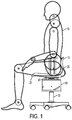
- Chair 15 may include a seat portion 20, a backrest 25, a base 30, and a resistive support mechanism 40 (not shown in Figure 1 ), within housing 60 according to the invention.
- An interface 45 is provided on the housing 60 and between the seat portion 20 for attaching the seat thereto.
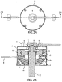
- Figure 2A shows a top view of the housing 60 and interface 45.
- Interface 45 is adapted to mount the seat of the chair thereon, and is alternatively referred to herein as a mounting surface.
- Chair 15 may further include various other elements known in the art, including but not limited to height adjustment mechanisms, arm rests, and various other adjustment devices that are otherwise unrelated to the resistive support mechanism as herein described.
- FIG. 2B there is shown one embodiment of the resistive support mechanism according to the invention, including a support bearing 50 connected to the mounting surface 45 and to the base 30.
- Support bearing 50 permits one or both of tilting and rotational- motion of the mounting surface 45 relative to the base 30.
- Base 30 includes a shoulder portion 32 that is friction fit into the support bearing 50, such that base 30 does not move relative to the support bearing 50.
- Mounting surface 45 is free to tilt or - rotate with respect to the support bearing 50 such that support bearing 50 permits one or more of rotational or tilt movement of the mounting surface 45 relative to the base 30.
- a housing 60 is the main body of support for the mounting surface 45, which preferably includes stand-offs to fasten a seating surface to the mechanism is preferably provided to contain within it all or most of the elements of the resistive support mechanism.
- the housing 60 also includes a bearing surface 75 for receiving at least a portion of the support bearing 50.
- the surfaces of support bearing 50 and bearing surface 75 will be provided such that minimal frictional forces are present between these surfaces so that movement on the support bearing 50 is relatively uninhibited.
- Housing 60 preferably extends directly from mounting surface 45 and is formed unitarily therewith.
- the functioning of bearings and bearing surfaces is generally known in the art and not further described herein.
- the invention also contemplates the use of functional alternatives to bearings and bearing surfaces that provide for the full two-degrees of freedom of movement made possible by support bearing 50 and bearing surface 75.
- a pivot ball 55 is positioned on a portion of the base 30.
- pivot ball 55 has a resistive force providing means acting on it to provide the resistive support to the mechanism.
- the resistive force providing means is preferably implemented by way of a resistance cartridge 40 that acts on the pivot ball 55. In this manner, the resistive and/or dampening forces are exerted perpendicular to the vertical plane of the mounting surface 45 resulting in a more stable and controlled ride compared to prior art devices.
- the aforementioned Thole patent allows the resilient material as therein arranged to undergo various compression and torque forces resulting in various compression and torque forces being applied to the resilient material.
- a resistance cartridge 40 is fixedly connected to the mounting surface 45 in a manner that allows the resistance cartridge 40 to undergo tilt and/or rotational- movement relative to the base 30 and to apply a resistive force on the base 30 as the resistance cartridge 40 and therefore the mounting surface 45 undergoes relative movement with respect to the base 30.
- the resistance cartridge -40 provides the core functionality of the resistive support mechanism of the invention.
- the resistance cartridge 40 includes therein resilient member 65b, pivot ball 55, and cartridge housing 70.
- the resilient member 65b is arranged in contact relation with the pivot ball 55, via extension member 65a, and with a wall 70 of the cartridge housing of the resistive cartridge 40 such that, in operation, the resilient member 65 is compressed by the relative movement between the resistance cartridge 40 and the pivot ball 55.
- pivot ball 55 has a snug but sliding interface with extension member 65a.
- extension member 65a is formed from a rigid material that forms a ring around the pivot ball 55 and extends radially outward thereform towards the wall 70.
- the sliding interface between the extension member 65a and the pivot ball 55 allows the entire mounting surface 45 to tilt while the resilient member 65b provides a dampening feature that prevents the mounting surface 45 from unrestrained movement, and permits smooth movement over the maximum range of motion to thereby provide the resistive support to the mounting surface 45, and any object attached thereto, such as seat 20 (of Figure 1 ).
- the resilient member 65b is preferably selected from the group consisting of an elastomeric ring, silicone, a gel, a series of rubber elements, and any similar materials know to have damping characteristics or otherwise able to resist relative movement when compressed or otherwise subjected to a force. It is also contemplated that a combination of resilient members may be employed to vary the resistance being applied across the range of motion available.
- the resilient member 65b may include a first resilient member in contact relation with the extension element 65a and a second resilient member in contact relation with the wall 70.
- the resilient member 65b is a viscoelastomeric material bonded to the wall 70 and to the extension element 65a.
- a viscoelastomeric material provides a damping effect where the material deforms, absorbs and distributes more of the load as it is compressed and slowly recovers when the load is removed. The result is that when the resistive support mechanism 40 is returning to a home position, the movement back to the home position is dampened and controlled based on the material properties.
- the use of a viscoelastomeric material allows the rate of resistance to be accentuated such that the flow properties of the resilient member are more prominent, thus providing for increased dampening. That is, viscoelastomeric materials have a response that exhibits both viscous and elastic properties when a load is applied and therefore hysteresis is observed.
- Wall 70 of the resistance cartridge 40 includes an outer surface that is capable of sliding vertically within the housing 60 to thereby permit the resistance cartridge 40 to have its vertical position adjusted within the housing 60, as will be described in further detail below.
- the resilient member 65b is a viscoelastomeric ring
- the extension element 65a is a rigid material in a ring shape articulating with the pivot ball 55 and radiating outward to compresses the resilient member 65b having damping properties.
- the second resilient member may be provided that includes a plurality of gels in contact with each other and/or the leading edge of the extension member 65a.
- the gels further away from the pivot ball 55 will have a higher density than those gels closer to the pivot ball 55, although variations of this are considered within the scope of the invention. This permits the resistance to tilting to be greater as the degree of tilt increases.
- the provision of the resilient members 65 as herein described allows the mounting surface 45, and the seat 20 mounted thereon, to be biased towards a home position, having no tilt or rotational due to pre-compression of the resilient members 65.
- the seat will return to an unbiased home position.
- a means for varying the resistive force acting on the pivot ball 55 is provided. This allows the resistance applied by the resistive cartridge to be increased or decreased depending on, for example, the intended use of the resistive support mechanism or the user. In the case of a chair, a larger user may require a higher resistive force than a small sized user.
- the means for varying the resistive force includes a spring 80 compressed between a bottom surface 85 of the housing 60 and an underside 95 of the resistance cartridge 40.
- a resistance lever 90 functionally attached to an interface plate 95 is preferably provided.
- the resistance lever 90 is adapted to be moveable to vary the position of the interface plate 95 under urging of the spring 80, and thereby to vary the position of the resistive cartridge 40 with respect to the base 30.
- the position of the resistance cartridge 40 with respect to the base 30, that is, how far up the base 30 the resistance cartridge 40 acts is determinative of the effective resistive force applied by the resistance cartridge 40, since the point of tilt/rotational is fixed. That is, the effective distance between the pivot ball 55 and the support bearing 50 is determinative of the resistive force applied by the resistance cartridge 40.
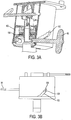
- spring 80 (not shown for ease of illustration) is used to bias the underside 95 of the resistance cartridge 40 and all parts internal thereto, within housing 60, to an uppermost vertical position, as would be dictated by the position of the lock pin 100, within helix 102.
- the position of pin 100, along the steps of helix 102 may be set by adjusting saddle 108 by moving resistance lever 90 within the steps of the helix 102.
- helix 102 is provided on both sides of the resistance cartridge 40, with one side including steps within which to move the lever 90 and the other side include corresponding steps within which pin 100 is provided to fix the other side within a corresponding step. It will be appreciated by a person skilled in the art that there is greater resistance in the system when the pin 100 is at a lower step within the helix 102, since the resistance cartridge 40 is further away from the point of rotation/tilt.
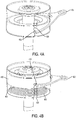
- FIG. 4A and 4B there is shown a variation of the means for varying the resistive force in which a spring 400 acts on an underside 405 of the cartridge housing 410 to bias the cartridge housing 410 to an uppermost position in a similar manner as described with respect to Figure 3 .
- the height of the cartridge housing is limited by the position of lever stops 415 within the series of steps 420.
- Lever 425 is moveable such that lever stops 415 may be brought to rest on a desired step 420. Accordingly, spring 400 exerts an upwards force on the resistance cartridge 440 such that resistance cartridge 440 is positioned at a location limited by the particular step in the series of steps 420 in which the lever stops 415 are positioned.
- a means for locking the resistance cartridge 40 at a any position in which the mounting surface 45 has undergone movement relative to the base is also provided.
- Such a locking means provides the benefit of allowing the seat, or other apparatus mounted on the mounting surface 45 to be locked in position, and to therefore prevent the mechanism from returning to its home position.
- the different embodiments of the means for locking herein described permit locking in either predetermined incremental positions, or at a free floating position.
- the inclusion of a means for locking may be of particular benefit where the resistive support mechanism is deployed in environments where it may not always be beneficial for the resistive functionality to be active, or in the alternative, to provide additional functionality whereby the mechanism may be locked at any position of tilt or rotation- during use.
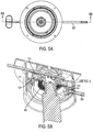
- the resistive support mechanism of this embodiment includes, within the resistive cartridge, a rigid plate 500 positioned at underside of the extension member 565.
- the rigid plate 500 has a surface having a plurality of locking elements 505 on a surface distal to the contact surface with the extension member 565.
- a locking pad 510 having a surface of complimentary locking elements 535 is provided and adapted to be brought into contact with the plurality of locking elements 505 of the rigid plate 500.
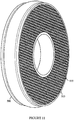
- FIG 11 An exemplary embodiment of the rigid plate 500 having the plurality of locking elements 505 is shown in Figure 11 .
- the plurality of locking elements 505 is provided by a knurled surface 530 on an underside of the rigid plate, as illustrated.
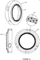
- a corresponding locking pad 510 is shown in Figure 12 , having a ridged knurled portion 535 that may be brought into and out of contact with the knurled surface 530 of the rigid plate 500.
- These surfaces described as the locking elements may also incorporate various alternative shapes and materials and combinations that provide a similar locking feature.
- One example, of an alternative locking pad and locking elements that may be used in an analogous manner as that described above are those referred to as reclosable fasteners such as that sold under the trade name Dual LockTM by 3MTM.
- locking means contemplated include systems similar to bicycle disk brakes, multi layer compression plates and rotors and pads, all of which may be applied to the invention in a manner analogous to the Preferably, the locking means of the invention is capable of being activated in either predetermined increments or at random engagement points as will be possible in the various embodiments described herein.
- a brake lever 525 is provided that is adapted to raise and lower the locking pad 510, for example, by way of a twist motion that activates a cam mechanism to thereby bring the complementary locking elements 535 of the locking pad 510 into and out of contact with the knurled surface 530 of the rigid plate 500.
- a means for adapting the brake lever 525 to be raised and lowered in this manner is the provision of an angled slot 540 that is sized and otherwise dimensioned to be friction fit with the brake lever 525.
- a support bearing 750 includes one, and preferably two bearing protrusions 705.
- the resistance cartridge preferably includes corresponding locking surfaces 710 that provide a region of contact with the bearing protrusions 705 that is adapted to be brought into a friction fit contact relationship with the protrusions 705 when a means for locking is activated.
- an adjustment lever 715 is provided to displace the resistance cartridge to a position in which its motion is locked.
- the adjustment lever 715 is adapted to apply a rotational motion by rotating the bearing protrusions 705 into contact relationship with the locking surfaces 710.
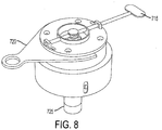
- Figure 8 shows a resistance cartridge according to this embodiment.
- Lever 715 may be rotated about a generally horizontal axis to permit the lever 715 to move, and then may be rotated about a generally horizontal axis to engage the locking features as described above.
- the locking mechanism that is the lever 715
- the locking mechanism may be activated and deactivated as required by a user by rotation about the horizontal axis, and may be used to effect locking by rotation about the vertical axis.
- a force adjustment lever 720 for raising or lowering the resistance cartridge to alter the portion of the base 725 on which the resistance cartridge acts to vary the resistive forces in the motion support mechanism, as has been described above.
- a locking means as described and illustrated with respect to Figures 7 and 8 may have a maximum range of tilt around the support bearing of approximately +/- fourteen degrees.
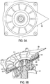
- the locking means of Figures 9A and 9B includes a lock rotational ball 905 positioned above the resistance cartridge 910.
- the lock rotational ball 905 is generally provided as herein described as a rotational ball about which the motion support mechanism of the invention is able to tilt and/or rotate.
- a lower lock surface disc 915 is provided in such a manner so as to be brought into frictional contact with the lock rotational ball 905. This is generally accomplished by raising or lowering the lock body 920 into and out of contact with the housing body 925 to provide an offsetting distance between the lock body 920 and the housing body 925.
- This movement also transfers the load onto lock surfaces 930 on an underside of the lock body 935 on a topside 940 of the rotational disk 915.
- the surfaces 930 and 940 have concentric ridges to provide for additional locking force. These surfaces may include a rubber gripping layer that is deformed when the surfaces are brought into contact to provide for the additional locking.
- a lock lever 950 is provided to engage and disengage the lock. This can be accomplished, for example, by allowing the lock lever 950 to be rotated about the vertical axis such that such rotation causes the lock body 920 to be displaced vertically to engage or disengage the lock.
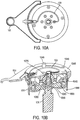
- FIG. 10A, 10B and 10C there is shown another embodiment of the invention including a support bearing 1050 connected to the mounting surface 1045 and to the base 1030.
- Support bearing 1050 permits one or both of tilting and rotational motion of the mounting surface 1045 relative to the base 1030.
- Base 1030 does not move relative to the support bearing 1050.
- Mounting surface 1045 is accordingly free to tilt or rotate with respect to the support bearing 1050 such that support bearing 1050 permits one or more of rotational and tilt movement of the mounting surface 1045 relative to the base 1030.
- a housing 1060 having mounting surface 1045, which may include stand offs 1046 to fasten a seating surface to the mechanism, extending therefrom is preferably provided to contain within it all or most of the elements of the resistive support mechanism within the resistance cartridge 1040.
- the housing 1060 also includes a bearing surface 1075 for receiving at least a portion of the support bearing 1050.
- a pivot ball 1055, within resistance cartridge 1040, is positioned on a portion of the base 1030.
- the resistance applied is varied by permitting the distance between the pivot ball 1055 and the support bearing 1050 to be varied, by adjusting the position on the base 1030 on which the pivot ball 1055 acts.
- Extension element 1063 is a rigid element extending from the pivot ball 1055 on which resilient member 1065 acts. As illustrated, resilient member 1065 is compressed between the extension element 1063 and a wall of the resistance cartridge 1040 to provide the resistance to tilt and/or rotation.
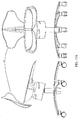
- a cable 1005 adapted to raise or lower the position of seat, or other surface atop the mounting surface that is being subject to resistive motion of the resistance cartridge 1010 with respect to the base 1015.
- the cable 1005 may be drawn by activation of the lever 1020 by rotation about the vertical axis.
- the cable 1005 may be provided within a cable tube, as illustrated, to prevent damage to the cable. According to the invention, rotation of the lever 1020 about the vertical axis releases and dispenses a length of the cable 1005 to activate an air cylinder atop the base 1015, which results in the cylinder being moved up or down.
- Various other hardware elements are illustrated, but not described as these are provided for facilitating installation or have been described with respect to previous embodiments of the invention.
Landscapes
- Engineering & Computer Science (AREA)
- General Engineering & Computer Science (AREA)
- Health & Medical Sciences (AREA)
- Dentistry (AREA)
- General Health & Medical Sciences (AREA)
- Mechanical Engineering (AREA)
- Pivots And Pivotal Connections (AREA)
- Chairs Characterized By Structure (AREA)
Description
- This application claims priority from United States Provisional Application No.
61/417,258, filed on November 25, 2010 61/475,010 filed on April 13, 2011 - The present invention relates generally to the field of control and support mechanisms, and more particularly to a resistive support mechanism, preferably for use in a chair.
- Various motion control and support devices are known in art to control and support tilt and/or rotational motion. Common prior art examples are found in chairs, such as office chairs that offer a variety of options for adjusting the tilt on a chair or restricting the degree to which a user of the chair is able to adjust and/or control the motion of the chair. A common example are office chairs that have various degrees of freedom and ranges of motion aimed at providing mobility, flexibility and optimal ergonomic positioning with minimal dynamic action. On problem associated with such prior art ergonomic designs is that they allow for an individual fit, but rarely are they readjusted as often as they should, so a user ends up sitting in a fixed position for prolonged periods of time when seated at an office desk. For example, these chairs are able to swivel, flexibly tilt in limited fore and aft plans and be raised and lowered as required by a user. Various mechanisms have been proposed or otherwise known in the art to provide some of the above-mentioned features. There are conventional adjustable chairs where adjustment is possible by way of several, independent adjusting means, to adjust, for example, chair height, angle, etc. In addition, active adjustment chairs provide for multi-directional adjustment based on the seating position of a user. Some problems associated with prior art systems include the complexity of the mechanisms involved, difficulty in operation, lack of fluid control over the motion of the tilt and/or rotation of the chair.
- Furthermore, other resistive support devices have been used where control and dampening of the motion available is more important, or where temporary motion may be desirable. These include, for example, construction worker supports, mining support devices, and exercise equipment. In the exercise equipment example, prior art support devices aim to provide a resistance against movement of a user, while the user is either trying to maintain a constant position or is otherwise partaking in an exercise activity. Resistive support devices in this example are generally targeted at improving the core strength of a user.
- The various prior art devices are generally restricted in the range of motion they support, and in the resistive forces that are applied. That is, resistive support is provided for only a small range of motion. Furthermore, prior art devices and mechanisms for providing such resistive support are generally not readily adaptable to different applications, and do not provide variable resistance throughout the range of motion. Furthermore, in the case of resistive support devices provided on chairs, such resistive support devices have heretofore been inadequate in providing core support and strengthening to a user on the chair, and have not provided a full range of resistive support throughout a full range of tilt and rotational motions. Some shortcomings of these prior art designs include a requirement that a pivot point for motion be at a distance significantly below the user's centre of mass, thereby requiring the user to lean their body more than to mobilize their pelvic and lower back skeletal structure minimizing their significant to the action of an active sitting surface. Some examples of such prior art devices include those shown in United States Patent No.
7,547,067 to Keilhauer and United States Patent No.6,997,511 to Marchand . - One such example of a prior art chair having a resistive support mechanism is shown in United States Patent No.
6,209,958 issued April 3, 2001 to Thole et al. Thole discloses one way of implementing a tilt control mechanism on a seating assembly. However, the Thole mechanism, while providing for universal tilt, does not allow for a full range of positions in which the chair can be locked, or for full flexibility in the degree of resistance. Thole discloses a tilt control mechanism for a char, where the tilt control mechanism defines a pivot connection between a seat assembly and a base, whereby the seat assembly effectively pivots about a pivot point in any direction extending radially from the pivot point. The tilt control mechanism includes an annular elastomeric ring which resists multi-directional tilting by mimicking a spring effect in the resistance, and further biases the seat assembly to a neutral position. The elastomeric ring has a contact area on which the tilting moment of the seat assembly acts which contact area can be selectively varied to adjust tilting resistance. Accordingly, the Thole mechanism tends to be large and bulky where a wide range of resistances is required. Furthermore, there is no discussion in Thole or features provided that result in proper support for the core muscles in a user's body. There is therefore a need in the art for a tilt mechanism for a chair, or other support surface, that addresses at least one of the deficiencies of Thole. - It is therefore an object of the invention to provide a novel resistive support mechanism for use with surfaces designed to support a user, such as chairs.
- According to one embodiment of the invention, there is provided a resistive motion support mechanism as defined in claim 1, for example for a chair, joined to a mounting surface and to a base for providing resistive support to the mounting surface as the mounting surface undergoes one or both of rotational and tilt movement relative to the base. The motion support mechanism includes a support bearing connected to the mounting surface and to the base which permits one or both of tilting and rotational motion of the mounting surface relative to the base, a pivot ball fixedly attached to a portion of the base, and, a resistance cartridge fixedly connected to the mounting surface such that the resistance cartridge undergoes movement relative to the base and applies a resistive force on the base as the mounting surface undergoes one or both of rotational and tilt movement. The resistance cartridge preferably includes cartridge housing and a resilient member in contact relation with the pivot ball and with a wall of the housing such that the resilient member is compressed by the relative movement between the resistance cartridge and the pivot ball to thereby provide the resistive support to the mounting surface.
- According to one aspect of the invention, the resilient member is preferably is selected from the group comprising an elastomeric ring, a silicone member, a dampening gel, a viscoelastomer, a bonded dampening material and a combination of same
- According to another aspect of the invention, the pivot ball includes an integral, rigid extension element and the resilient member is in contact relation with the rigid extension element and with said wall of said housing.
- According to another aspect of the invention, the resilient member includes one or more gels in contact relation with each other.
- According to another aspect of the invention, the one or more gels is preferably a first gel in contact with the first resilient member, and a second gel in contact with the first gel and with the wall of the housing; wherein the second gel has a higher density than the first gel.
- According to another aspect of the invention, the resilient member is adapted to bias the mounting surface to a home position.
- According to another aspect of the invention, wherein the housing of the resistance cartridge includes a bearing surface for receiving at least a portion of the support bearing.
- According to another aspect of the invention, there is further provided a means for locking the resistance cartridge at a position in which the mounting surface has undergone the movement relative to the base
- According to another aspect of the invention, there is further provided a rigid plate connected to an underside of the resilient member, wherein the rigid plate has a surface having a plurality of locking elements on a surface distal to the resilient member, and wherein the means for locking comprises a locking pad having a surface of complimentary locking elements adapted to be brought into contact with the plurality of locking elements on the rigid plate.
- According to another aspect of the invention, there is further provided a brake lever for moving the locking pad into and out of contact with the rigid plate.
- According to another aspect of the invention, there is further provided a protruding element extending from the support bearing, and the resistance cartridge further comprising a locking surface for receiving the protruding element; wherein the locking surface provides a region of contact with the protruding element that is adapted to be brought into friction fit contact relationship with the protruding element upon activation of the means for locking.
- According to another aspect of the invention, the means for locking comprises an adjustment lever adapted to bring the locking surface into the friction fit contact with the protruding element.
- According to another aspect of the invention, the locking surface is provided on a portion of the housing of the resistance cartridge, and the adjustment lever comprises a height adjustment lever adapted to raise or lower the portion of the housing into and out of the friction fit contact relationship.
- According to another aspect of the invention, the locking surface further restricts movement of the protruding element such that a maximum range of tilt around the support bearing is approximately fourteen degrees.
- According to another aspect of the invention, there is further provided a means for varying the resistive force.
- According to another aspect of the invention, the means for varying said resistive force comprises a means for varying the distance between said support bearing and said pivot ball such that said pivot ball is functionally attached at a variable position on said base.
- According to another aspect of the invention, the means for varying the distance comprises a spring within the housing and adapted to apply a force onto the resistance cartridge.
- According to another aspect of the invention, the housing includes two or more stepped notches offset vertically from each other and the resistance lever is moveable between each of the two or more stepped notches to vary the effective length of the spring.
- According to another aspect of the invention, the stepped notches are further offset horizontally from each other to facilitate moving the resistance lever between each of the notches.
- According to another aspect of the invention, the means for varying the resistive force includes a means for varying a contact area on the base on which the resistance cartridge applies the resistive force to thereby vary the resistive force.
- According to another aspect of the invention, the means for varying a contact area includes a vertical position adjustment mechanism effective to increase or decrease the distance between the support bearing and the pivot ball to thereby vary a distance between a point of contact of the resistive force and a point about which the tilt motion occurs resulting in a varying of the resistive force applied onto the base.
- According to another aspect of the invention, the mounting surface is adapted to mount the base of a seat thereon, and the base comprises the base of a chair.
- According to another embodiment of the invention, there is provided a chair having a chair base, a seat and a motion support mechanism as defined in claim 1, wherein the seat is mounted onto the mounting surface and the chair base is integral with the base of the motion support mechanism.
- According to another embodiment of the invention, there is provided a chair having a seat, a base, and a motion support mechanism as defined in claim 1, joined to the base and the seat. The motion support mechanism providing resistive support to the seat as the seat undergoes one or both of rotational- and tilt movement relative to the base. The motion support mechanism includes a support bearing connected to the seat and to the base which permits one or both of tilting and rotational- motion of the seat relative to the base, a pivot ball sized fixedly attached to a portion of the base, and a resistance cartridge fixedly connected to the seat such that the resistance cartridge undergoes movement relative to the base and applies a resistive force on the base as the seat undergoes the one or both of rotational- and tilt movement. The resistance cartridge preferably includes a housing and a resilient member in contact relation with the pivot ball and with a wall of the housing such that the resilient member is compressed by the relative movement between the resistance cartridge and the pivot ball to thereby provide the resistive support to the seat.
- Embodiments will now be described, by way of example only, with reference to the attached Figures, wherein:
-
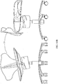
Figure 1 shows a user sitting on a chair incorporating the resistive motion support mechanism according to the invention. -
Figures 2A and 2B are top and sectional views, respectively of the resistive motion support mechanism according to an embodiment of the invention. -
Figures 3A and 3B are sectional and side views, respectively illustrating a resistance varying means according to one aspect of the invention. -
Figures 4A and 4B are sectional and side views, respectively illustrating a resistance varying means according to another aspect of the invention. -
Figures 5A and 5B are top and sectional views, respectively illustrating a locking means according to an embodiment of the invention. -
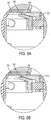
Figures 6A and 6B are detail views showing a portion ofFigure 5B when the locking means is in the locked and unlocked position, respectively. -
Figures 7A and 7B are sectional views of an alternative locking means in the unlocked and locked position, respectively. -
Figure 8 is a perspective view of the resistive support mechanism according to another embodiment of the invention. -
Figures 9A and 9B are top and sectional views according to another embodiment of the invention. -
Figures 10A, 10B , and10C are top, sectional and exploded views, respectively according to another embodiment of the invention that includes a height adjustment means -
Figures 11 and12 are detail views of elements of the locking means ofFigure 5 . -
Figure 13A and13B illustrate a chair having undergone tilt motion according to the invention. - The preferred embodiments of the invention as described hereinbelow teach a motion support mechanism capable of providing resistive support, and referred to interchangeably as a motion support mechanism and a resistive motion support mechanism. In the preferred embodiment, the invention is applied for use with a chair, such as an office chair. The resistive support mechanisms described herein, help in providing the additional benefit of improving core strength in a user on the seat and mobilize the joints of the pelvis and vertebrae, thereby for example preventing contractures and atrophy of the supportive soft tissue and in fact enhancing the endurance of the relevant supportive musculature around these joints to counter the potential of back pain and injury as a result of chronic static sitting by allowing the user to be constantly counteracting the rotational motion of the ball. This ability to affect continuous movement and/or dynamic movement further aids in improving blood circulation, as well as the redistribution of sitting pressures to reduce pressure points which directly correlates to the sitting comfort of the user.
- Some embodiments of the invention also allow the user to restrict this movement either by increasing/decreasing the resistance and or locking the system in a desired position. For example, one such desirable position would be such that the user is allowed to sit with their knees lower than their hips promoting a more upright pelvis and natural extension and balance of the spine. The invention also permits accommodation of mild to moderate orthopedic abnormalities allowing for an individual's hip, for example, to sit lower on one side versus the other and by doing so allow the spine to be erect whereas on a level fixed surface, the spine would be challenged to be upright further complicating spine balance and alignment, pain and injury. These features may also be advantageously used to accommodate other factors that affect proper pelvic positioning such as a wallet that might tend to cause a similar uneven positioning of the pelvis.
- Furthermore, the motion support mechanism as herein described may be applied to other seating devices, such as dentists' chairs, lab stools, car seats, gaming chairs, leisure chairs such as bar stools, amusement park rides, children's school stools and similar devices where it would be beneficial to provide resistive support to a user. Other applications include devices meant to support a user in a standing position, such as construction support surfaces or pedestals. In the case of a dental hygienist using a hygienist's chair, for example, while the user reaches to perform their tasks, the free movement of the seat by way of the motion support mechanism prevents an acceleration of forces through the lower lumbar region of the user thereby reducing the potential of strains associated with this movement, which contributes to user pain and injury that may be experienced while sitting on a fixed level seating surface.
- Referring now to
Figure 1 , there is shown a user 10 seated on achair 15.Chair 15 may include aseat portion 20, abackrest 25, abase 30, and a resistive support mechanism 40 (not shown inFigure 1 ), withinhousing 60 according to the invention. Aninterface 45 is provided on thehousing 60 and between theseat portion 20 for attaching the seat thereto.Figure 2A shows a top view of thehousing 60 andinterface 45.Interface 45 is adapted to mount the seat of the chair thereon, and is alternatively referred to herein as a mounting surface.Chair 15 may further include various other elements known in the art, including but not limited to height adjustment mechanisms, arm rests, and various other adjustment devices that are otherwise unrelated to the resistive support mechanism as herein described. For clarity, in the description that follows, reference to a vertical axis refers to an axis coincidental with the cylindrical axis of thebase 30. Reference to a horizontal axis refers to an axis perpendicular to the vertical axis. Furthermore, references to tilt and/or rotational motion have their ordinary meaning, wherein tilt motion refers to rotation about the horizontal axis and rotational motion refers to rotation about the vertical axis. The description further describes elements of the invention required to put the invention into practice and further sets forth a preferred embodiment as contemplated by the invention. However, various hardware and ordinary mechanical elements that would be used to assemble a mechanism or chair according to the invention may not be described and are considered within the abilities of a person skilled in the art.Figures 13A and13B illustrate thechair 15 exhibiting two degrees of freedom in its motion, as theresistive support mechanism 40 of the present invention provides. - Referring to
Figure 2B , there is shown one embodiment of the resistive support mechanism according to the invention, including a support bearing 50 connected to the mountingsurface 45 and to thebase 30. Support bearing 50 permits one or both of tilting and rotational- motion of the mountingsurface 45 relative to thebase 30.Base 30 includes ashoulder portion 32 that is friction fit into the support bearing 50, such thatbase 30 does not move relative to thesupport bearing 50. Mountingsurface 45 is free to tilt or - rotate with respect to the support bearing 50 such that support bearing 50 permits one or more of rotational or tilt movement of the mountingsurface 45 relative to thebase 30. Ahousing 60 is the main body of support for the mountingsurface 45, which preferably includes stand-offs to fasten a seating surface to the mechanism is preferably provided to contain within it all or most of the elements of the resistive support mechanism. Preferably, thehousing 60 also includes a bearingsurface 75 for receiving at least a portion of thesupport bearing 50. The surfaces of support bearing 50 and bearingsurface 75 will be provided such that minimal frictional forces are present between these surfaces so that movement on the support bearing 50 is relatively uninhibited.Housing 60 preferably extends directly from mountingsurface 45 and is formed unitarily therewith. The functioning of bearings and bearing surfaces is generally known in the art and not further described herein. The invention also contemplates the use of functional alternatives to bearings and bearing surfaces that provide for the full two-degrees of freedom of movement made possible by support bearing 50 and bearingsurface 75. - A
pivot ball 55 is positioned on a portion of thebase 30. As will be described below,pivot ball 55 has a resistive force providing means acting on it to provide the resistive support to the mechanism. Various ways of implementing the resistive force providing means are contemplated. The resistive force providing means is preferably implemented by way of aresistance cartridge 40 that acts on thepivot ball 55. In this manner, the resistive and/or dampening forces are exerted perpendicular to the vertical plane of the mountingsurface 45 resulting in a more stable and controlled ride compared to prior art devices. For example, the aforementioned Thole patent allows the resilient material as therein arranged to undergo various compression and torque forces resulting in various compression and torque forces being applied to the resilient material. - In the embodiment of
Figure 2B , aresistance cartridge 40 is fixedly connected to the mountingsurface 45 in a manner that allows theresistance cartridge 40 to undergo tilt and/or rotational- movement relative to thebase 30 and to apply a resistive force on the base 30 as theresistance cartridge 40 and therefore the mountingsurface 45 undergoes relative movement with respect to thebase 30. The resistance cartridge -40, provides the core functionality of the resistive support mechanism of the invention. In this embodiment, theresistance cartridge 40 includes thereinresilient member 65b,pivot ball 55, andcartridge housing 70. Theresilient member 65b is arranged in contact relation with thepivot ball 55, viaextension member 65a, and with awall 70 of the cartridge housing of theresistive cartridge 40 such that, in operation, the resilient member 65 is compressed by the relative movement between theresistance cartridge 40 and thepivot ball 55. Preferably,pivot ball 55 has a snug but sliding interface withextension member 65a. When the mountingsurface 45 is tilted, theresilient material 65b is compressed between thewall 70 and theextension member 65a. Preferably,extension member 65a is formed from a rigid material that forms a ring around thepivot ball 55 and extends radially outward thereform towards thewall 70. The sliding interface between theextension member 65a and thepivot ball 55 allows the entire mountingsurface 45 to tilt while theresilient member 65b provides a dampening feature that prevents the mountingsurface 45 from unrestrained movement, and permits smooth movement over the maximum range of motion to thereby provide the resistive support to the mountingsurface 45, and any object attached thereto, such as seat 20 (ofFigure 1 ). - The
resilient member 65b is preferably selected from the group consisting of an elastomeric ring, silicone, a gel, a series of rubber elements, and any similar materials know to have damping characteristics or otherwise able to resist relative movement when compressed or otherwise subjected to a force. It is also contemplated that a combination of resilient members may be employed to vary the resistance being applied across the range of motion available. For example, theresilient member 65b may include a first resilient member in contact relation with theextension element 65a and a second resilient member in contact relation with thewall 70. In a preferred embodiment of the invention, theresilient member 65b is a viscoelastomeric material bonded to thewall 70 and to theextension element 65a. The use of a viscoelastomeric material provides a damping effect where the material deforms, absorbs and distributes more of the load as it is compressed and slowly recovers when the load is removed. The result is that when theresistive support mechanism 40 is returning to a home position, the movement back to the home position is dampened and controlled based on the material properties. The use of a viscoelastomeric material allows the rate of resistance to be accentuated such that the flow properties of the resilient member are more prominent, thus providing for increased dampening. That is, viscoelastomeric materials have a response that exhibits both viscous and elastic properties when a load is applied and therefore hysteresis is observed. -
Wall 70 of theresistance cartridge 40 includes an outer surface that is capable of sliding vertically within thehousing 60 to thereby permit theresistance cartridge 40 to have its vertical position adjusted within thehousing 60, as will be described in further detail below.. In a preferred embodiment, theresilient member 65b is a viscoelastomeric ring, and theextension element 65a is a rigid material in a ring shape articulating with thepivot ball 55 and radiating outward to compresses theresilient member 65b having damping properties. It is also contemplated that the second resilient member may be provided that includes a plurality of gels in contact with each other and/or the leading edge of theextension member 65a. Where a plurality of gels are included, it is preferably that the gels further away from thepivot ball 55 will have a higher density than those gels closer to thepivot ball 55, although variations of this are considered within the scope of the invention. This permits the resistance to tilting to be greater as the degree of tilt increases. - Furthermore, the provision of the resilient members 65 as herein described allows the mounting
surface 45, and theseat 20 mounted thereon, to be biased towards a home position, having no tilt or rotational due to pre-compression of the resilient members 65. Thus, if a user seated in the chair leans in one direction and is supported there by the resistive support mechanism as described, but subsequently stands up, the seat will return to an unbiased home position. - According to an aspect of the invention, a means for varying the resistive force acting on the
pivot ball 55 is provided. This allows the resistance applied by the resistive cartridge to be increased or decreased depending on, for example, the intended use of the resistive support mechanism or the user. In the case of a chair, a larger user may require a higher resistive force than a small sized user. In addition, regardless of size, the user may wish to have more or less resistance, which will allow them the possibility of more recruitment of core musculature to affect an exercise phenomena, and opportunity to mobilize the joints of their pelvis and vertebral regions and or a reduction of forces experienced on the sitting support soft tissue and joints in question when the user may otherwise be required to make repetitive movements as may be best illustrated by the work of a dental hygienist as an example. In the illustrated embodiment ofFigure 2B , the means for varying the resistive force includes aspring 80 compressed between abottom surface 85 of thehousing 60 and anunderside 95 of theresistance cartridge 40. In order to vary the force applied to thereby vary the resistive force in the resistance cartridge, aresistance lever 90, functionally attached to aninterface plate 95 is preferably provided. Theresistance lever 90 is adapted to be moveable to vary the position of theinterface plate 95 under urging of thespring 80, and thereby to vary the position of theresistive cartridge 40 with respect to thebase 30. As will be appreciated by a person skilled in the art, the position of theresistance cartridge 40 with respect to thebase 30, that is, how far up the base 30 theresistance cartridge 40 acts, is determinative of the effective resistive force applied by theresistance cartridge 40, since the point of tilt/rotational is fixed. That is, the effective distance between thepivot ball 55 and the support bearing 50 is determinative of the resistive force applied by theresistance cartridge 40. Referring toFigures 3A and 3B , spring 80 (not shown for ease of illustration) is used to bias theunderside 95 of theresistance cartridge 40 and all parts internal thereto, withinhousing 60, to an uppermost vertical position, as would be dictated by the position of thelock pin 100, withinhelix 102. In this embodiment, the position ofpin 100, along the steps ofhelix 102, may be set by adjustingsaddle 108 by movingresistance lever 90 within the steps of thehelix 102. It should be noted thathelix 102 is provided on both sides of theresistance cartridge 40, with one side including steps within which to move thelever 90 and the other side include corresponding steps within whichpin 100 is provided to fix the other side within a corresponding step. It will be appreciated by a person skilled in the art that there is greater resistance in the system when thepin 100 is at a lower step within thehelix 102, since theresistance cartridge 40 is further away from the point of rotation/tilt. - Various other implementations and embodiments of the invention are described below, however, the principle of operation in that there is a support bearing and a pivot ball provided as described above. Furthermore, there is preferably provided a means for varying the resistive force by varying the distance between the pivot ball on which the resilient material acts, and the support bearing. Referring now to
Figures 4A and 4B , there is shown a variation of the means for varying the resistive force in which aspring 400 acts on anunderside 405 of thecartridge housing 410 to bias thecartridge housing 410 to an uppermost position in a similar manner as described with respect toFigure 3 . In this embodiment, however, the height of the cartridge housing is limited by the position of lever stops 415 within the series ofsteps 420.Lever 425 is moveable such that lever stops 415 may be brought to rest on a desiredstep 420. Accordingly,spring 400 exerts an upwards force on the resistance cartridge 440 such that resistance cartridge 440 is positioned at a location limited by the particular step in the series ofsteps 420 in which the lever stops 415 are positioned. - According to another aspect of the invention, a means for locking the
resistance cartridge 40 at a any position in which the mountingsurface 45 has undergone movement relative to the base is also provided. Such a locking means provides the benefit of allowing the seat, or other apparatus mounted on the mountingsurface 45 to be locked in position, and to therefore prevent the mechanism from returning to its home position. The different embodiments of the means for locking herein described permit locking in either predetermined incremental positions, or at a free floating position. The inclusion of a means for locking may be of particular benefit where the resistive support mechanism is deployed in environments where it may not always be beneficial for the resistive functionality to be active, or in the alternative, to provide additional functionality whereby the mechanism may be locked at any position of tilt or rotation- during use. - Referring to
Figures 5A, 5B and6A, 6B , there is shown an embodiment of the locking means according to the invention. The resistive support mechanism of this embodiment includes, within the resistive cartridge, arigid plate 500 positioned at underside of theextension member 565. Therigid plate 500 has a surface having a plurality of lockingelements 505 on a surface distal to the contact surface with theextension member 565. In order to lock the resistive support mechanism in position, alocking pad 510 having a surface of complimentary locking elements 535 (shown inFigure 12 ) is provided and adapted to be brought into contact with the plurality of lockingelements 505 of therigid plate 500. When the lockingelements 505 are engaged with thecomplimentary locking elements 535, further tilt and/or rotational motion is prevented. An exemplary embodiment of therigid plate 500 having the plurality of lockingelements 505 is shown inFigure 11 . In the illustrated embodiment, the plurality of lockingelements 505 is provided by aknurled surface 530 on an underside of the rigid plate, as illustrated. Acorresponding locking pad 510 is shown inFigure 12 , having a ridgedknurled portion 535 that may be brought into and out of contact with theknurled surface 530 of therigid plate 500. These surfaces described as the locking elements may also incorporate various alternative shapes and materials and combinations that provide a similar locking feature. One example, of an alternative locking pad and locking elements that may be used in an analogous manner as that described above are those referred to as reclosable fasteners such as that sold under the trade name Dual Lock™ by 3M™. - Other locking means contemplated include systems similar to bicycle disk brakes, multi layer compression plates and rotors and pads, all of which may be applied to the invention in a manner analogous to the Preferably, the locking means of the invention is capable of being activated in either predetermined increments or at random engagement points as will be possible in the various embodiments described herein.
- Referring back to
Figure 5B , abrake lever 525 is provided that is adapted to raise and lower thelocking pad 510, for example, by way of a twist motion that activates a cam mechanism to thereby bring thecomplementary locking elements 535 of thelocking pad 510 into and out of contact with theknurled surface 530 of therigid plate 500. Referring to the detail ofFigure 12 , one embodiment of a means for adapting thebrake lever 525 to be raised and lowered in this manner is the provision of an angled slot 540 that is sized and otherwise dimensioned to be friction fit with thebrake lever 525. Sliding thebrake lever 525 on an upwards incline will bring thelocking pad 510 into contact with theknurled surface 530, while sliding thebrake lever 525 on a downwards incline will disengage thelocking pad 510 from theknurled surface 530. The angle of the slot and dimensions of the slot and thebrake lever 525 will be determined in such a manner that the brake lever requires a minimum force to activate that is greater than the forces applied during operation to prevent accidental movement of thebrake lever 525. - Having thus described a presently preferred embodiment of the invention, including the resistance cartridge, and optional means for varying the resistance and for locking the motion support mechanism in a particular position, various alternatives will now be described. Specifically, the alternatives relate to alternate means for varying the resistance and/or for locking the motion support mechanism. It will be understood by those skilled in the art that the invention is not limited to particular combinations of the embodiments of the resistance cartridge, means for varying the resistance and means for locking in the combinations as described. Combinations of the resistance cartridge, means for varying the resistance, and means for locking that are herein described are contemplated by the invention, which is only limited by the claims at the end of the specification. In the description that follows, elements common to the description above are not described in further detail, and their operation will be apparent to a person skilled in the art, having regard thereto.
- Referring now to
Figures 7A and 7B , there is shown an embodiment of the invention in which asupport bearing 750 includes one, and preferably two bearingprotrusions 705. The resistance cartridge preferably includes corresponding lockingsurfaces 710 that provide a region of contact with the bearingprotrusions 705 that is adapted to be brought into a friction fit contact relationship with theprotrusions 705 when a means for locking is activated. In order to activate the lock, anadjustment lever 715 is provided to displace the resistance cartridge to a position in which its motion is locked. Theadjustment lever 715 is adapted to apply a rotational motion by rotating the bearingprotrusions 705 into contact relationship with the locking surfaces 710.Figure 8 shows a resistance cartridge according to this embodiment.Lever 715 may be rotated about a generally horizontal axis to permit thelever 715 to move, and then may be rotated about a generally horizontal axis to engage the locking features as described above. In this manner, the locking mechanism, that is thelever 715, may be activated and deactivated as required by a user by rotation about the horizontal axis, and may be used to effect locking by rotation about the vertical axis. Also shown inFigure 8 , is aforce adjustment lever 720 for raising or lowering the resistance cartridge to alter the portion of the base 725 on which the resistance cartridge acts to vary the resistive forces in the motion support mechanism, as has been described above. In practice, a locking means as described and illustrated with respect toFigures 7 and8 may have a maximum range of tilt around the support bearing of approximately +/- fourteen degrees. - It has been discovered that adapting the resistive support mechanism according to the invention to have a range of tilt of approximately fourteen degrees allows for the effective mobilization of the joints involved to optimize the range of motion and to ensure a reasonable limit for safety considerations.
- Referring now to
Figures 9A and 9B , there is shown another embodiment of a locking means according to the invention. The locking means ofFigures 9A and 9B includes a lockrotational ball 905 positioned above theresistance cartridge 910. The lockrotational ball 905 is generally provided as herein described as a rotational ball about which the motion support mechanism of the invention is able to tilt and/or rotate. A lowerlock surface disc 915 is provided in such a manner so as to be brought into frictional contact with the lockrotational ball 905. This is generally accomplished by raising or lowering thelock body 920 into and out of contact with thehousing body 925 to provide an offsetting distance between thelock body 920 and thehousing body 925. This movement also transfers the load onto lock surfaces 930 on an underside of thelock body 935 on atopside 940 of therotational disk 915. Thesurfaces lock lever 950 is provided to engage and disengage the lock. This can be accomplished, for example, by allowing thelock lever 950 to be rotated about the vertical axis such that such rotation causes thelock body 920 to be displaced vertically to engage or disengage the lock. - Referring to
Figures 10A, 10B and10C , there is shown another embodiment of the invention including asupport bearing 1050 connected to the mountingsurface 1045 and to thebase 1030.Support bearing 1050 permits one or both of tilting and rotational motion of the mountingsurface 1045 relative to thebase 1030.Base 1030 does not move relative to thesupport bearing 1050. Mountingsurface 1045 is accordingly free to tilt or rotate with respect to thesupport bearing 1050 such that support bearing 1050 permits one or more of rotational and tilt movement of the mountingsurface 1045 relative to thebase 1030. Ahousing 1060 having mountingsurface 1045, which may includestand offs 1046 to fasten a seating surface to the mechanism, extending therefrom is preferably provided to contain within it all or most of the elements of the resistive support mechanism within theresistance cartridge 1040. Preferably, thehousing 1060 also includes abearing surface 1075 for receiving at least a portion of thesupport bearing 1050. - A
pivot ball 1055, withinresistance cartridge 1040, is positioned on a portion of thebase 1030. As described with respect to previous embodiments of the invention, the resistance applied is varied by permitting the distance between thepivot ball 1055 and thesupport bearing 1050 to be varied, by adjusting the position on thebase 1030 on which thepivot ball 1055 acts.Extension element 1063 is a rigid element extending from thepivot ball 1055 on whichresilient member 1065 acts. As illustrated,resilient member 1065 is compressed between theextension element 1063 and a wall of theresistance cartridge 1040 to provide the resistance to tilt and/or rotation. - In this embodiment, there is provided a
cable 1005 adapted to raise or lower the position of seat, or other surface atop the mounting surface that is being subject to resistive motion of theresistance cartridge 1010 with respect to the base 1015. Thecable 1005 may be drawn by activation of thelever 1020 by rotation about the vertical axis. Thecable 1005 may be provided within a cable tube, as illustrated, to prevent damage to the cable. According to the invention, rotation of thelever 1020 about the vertical axis releases and dispenses a length of thecable 1005 to activate an air cylinder atop the base 1015, which results in the cylinder being moved up or down. Various other hardware elements are illustrated, but not described as these are provided for facilitating installation or have been described with respect to previous embodiments of the invention. - The above-described embodiments are intended to be examples of the present invention and alterations and modifications may be effected thereto, by those of skill in the art, without departing from the scope of the invention that is defined solely by the claims appended hereto. For example, various materials may be used in providing the elastomeric ring or gels in the resistance cartridge described above. Furthermore, other means of providing the damping and/or resistive properties other than by way of such materials are also contemplated, for example, springs. Furthermore, other means for varying the resistance applied are also contemplated. The presently preferred embodiments as herein described are to be considered illustrative of applicant's invention. Similarly, other means for locking the support mechanism of the invention are also contemplated.
- It has also been discovered that the positioning of the support bearing of the invention being immediately beneath and close to the user's centre of mass provides the unexpected benefit of more acutely affecting the mobilization of the user's joints compared to prior art mechanisms. Prior art active sitting solutions have pivot points further from the user, resulting more in a lean of the entire body of the user rather than a mobilization of critical joints.
Claims (15)
- A resistive motion support mechanism joined to a mounting surface (45) and to a base (30) for providing resistive support to the mounting surface (45) as the mounting surface (45) undergoes one or both of rotational and tilt movement relative to the base (30), the motion support mechanism comprising:a support bearing (50) connected to the mounting surface (45) and to the base (30) which permits one or both of tilting and rotational motion of the mounting surface (45) relative to the base (30), wherein the base (30) includes a shoulder portion (32) that is friction fit into the support bearing (50) such that the base (30) does not move relative to the support bearing (50);a pivot ball (55) functionally attached to a portion of the base (30); and,a resistance cartridge (40) fixedly connected to the mounting surface (45) such that said resistance (40) cartridge undergoes movement relative to the base (30) and applies a resistive force on the base (30) as the mounting surface (45) undergoes said one or both of rotational and tilt movement;wherein said resistance cartridge (40) includes:a cartridge housing (60); and,a resilient member (65b) in contact relation with said pivot ball (55) and with a wall (70) of said housing (60) such that said resilient member (65b) is compressed by the relative movement between said resistance cartridge (40) and said pivot ball (55) to thereby provide the resistive support to the mounting surface (45).
- A mechanism according to claim 1, wherein said resilient member (65b) is adapted to bias said mounting surface (45) to a home position; and is selected from the group comprising an elastomeric ring, a silicone member, a dampening gel, a viscoelastomer, a bonded dampening material and a combination of same.
- A mechanism according to claim 1, wherein said resilient member (65b) comprises one or more gels in contact relation with each other.
- A mechanism according to claim 3, wherein said one or more gels comprises a first gel in contact with a rigid extension element (65a) of said pivot ball (55), and a second gel in contact with said first gel and with said wall (70) of said housing (60); wherein said second gel has a higher density than said first gel.
- A mechanism according to any one of claims 1 to 4, wherein said housing (60) of said resistance cartridge (40) includes a bearing surface (75) for receiving at least a portion of said support bearing (50).
- A mechanism according to any one of claims 1 to 5, further comprising a means for locking said resistance cartridge (40) at a position in which said mounting surface (45) has undergone said movement relative to said base (30) and a rigid plate (500) connected to an underside of said resilient member (565), wherein said rigid plate (500) has a surface having a plurality of locking elements (505) on a surface distal to said resilient member (565), and wherein said means for locking comprises a locking pad (510) having a surface of complimentary locking elements (535) adapted to be brought into contact with said plurality of locking elements (505) on said rigid plate (500).
- A mechanism according to claim 6, further comprising a brake lever (525) for moving said locking pad (510) into and out of contact with said rigid plate (500).
- A mechanism according to claim 6, further comprising a protruding element (705) extending from said support bearing (750), and said resistance cartridge (40) further comprising a locking surface (710) for receiving said protruding element (705); wherein said locking surface (710) provides a region of contact with said protruding element (705) that is adapted to be brought into friction fit contact relationship with said protruding element (705) upon activation of said means for locking.
- A mechanism according to claim 8, wherein said means for locking comprises an adjustment lever (715) adapted to bring said locking surface (710) into said friction fit contact with said protruding element (705) and wherein said locking surface (710) is provided on a portion of said housing (60) of said resistance cartridge (40), and said adjustment lever (715) comprises a lever adapted to rotate said portion of said housing (60) into and out of said friction fit contact relationship.
- A mechanism according to any one of claims 1 to 9, further comprising a means for varying said resistive force.
- A mechanism according to claim 10, wherein said means for varying said resistive force comprises a means for varying the distance between said support bearing (50) and said pivot ball (55) such that said pivot ball (55) is functionally attached at a variable position on said base (30), wherein said means for varying the distance optionally comprises a spring (80) within said housing (60) and adapted to apply a force onto said resistance cartridge (40).
- A mechanism according to claim 11, further comprising a resistance lever (90) in functional relationship with said spring (80); said resistance lever (90) being moveable to vary the effective length of said spring (80) and thereby vary the force applied by said spring (80) on said resilient member (65b).
- A mechanism according to claim 10, wherein said means for varying said resistive force comprises a means for varying the location of a contact area on said base (30) on which said resistance cartridge (40) applies said resistive force to thereby vary said resistive force; wherein said means for varying a contact area optionally comprises a vertical position adjustment mechanism effective to increase or decrease the distance between said support bearing (50) and said pivot ball (55) to thereby vary a distance between a point of contact of said resistive force and a point about which said tilt motion occurs resulting in a varying of said resistive force applied onto said base (30).
- A mechanism according to any one of claims 1 to 13, wherein said mounting surface (45) is adapted to mount the base (30) of a seat (20) thereon, and said base (30) comprises the base (30) of a chair (15).
- A chair having a seat (20), a base (30), and a motion support mechanism joined to the base (30) and the seat (20); said motion support mechanism providing resistive support to the seat (20) as the seat (20) undergoes one or both of rotational and tilt movement relative to the base (30), the motion support mechanism being the resistive motion support mechanism of claim 1.
Applications Claiming Priority (3)
| Application Number | Priority Date | Filing Date | Title |
|---|---|---|---|
| US41725810P | 2010-11-25 | 2010-11-25 | |
| US201161475010P | 2011-04-13 | 2011-04-13 | |
| PCT/CA2011/050733 WO2012068688A1 (en) | 2010-11-25 | 2011-11-24 | Resistive support mechanism |
Publications (3)
| Publication Number | Publication Date |
|---|---|
| EP2642900A1 EP2642900A1 (en) | 2013-10-02 |
| EP2642900A4 EP2642900A4 (en) | 2014-12-03 |
| EP2642900B1 true EP2642900B1 (en) | 2017-05-03 |
Family
ID=46145331
Family Applications (1)
| Application Number | Title | Priority Date | Filing Date |
|---|---|---|---|
| EP11843000.8A Active EP2642900B1 (en) | 2010-11-25 | 2011-11-24 | Resistive support mechanism |
Country Status (14)
| Country | Link |
|---|---|
| US (1) | US9211013B2 (en) |
| EP (1) | EP2642900B1 (en) |
| JP (1) | JP5917547B2 (en) |
| KR (1) | KR20140035312A (en) |
| CN (1) | CN103298374B (en) |
| AU (1) | AU2011334529B2 (en) |
| CA (1) | CA2816224C (en) |
| DK (1) | DK2642900T3 (en) |
| IL (1) | IL226487A0 (en) |
| MX (1) | MX339036B (en) |
| MY (1) | MY158976A (en) |
| SG (1) | SG190365A1 (en) |
| WO (1) | WO2012068688A1 (en) |
| ZA (1) | ZA201303634B (en) |
Families Citing this family (30)
| Publication number | Priority date | Publication date | Assignee | Title |
|---|---|---|---|---|
| FR2992912B1 (en) * | 2012-07-03 | 2014-07-11 | Renault Sa | SEAT BACK FOLDING DEVICE |
| DE202012010417U1 (en) * | 2012-10-23 | 2012-12-17 | Mey Chair Systems Gmbh | Spring joint module for an industrial chair, industrial chair |
| EP3462986B1 (en) | 2016-05-24 | 2021-06-30 | Engell, Maria Terese | Balance chair |
| DE102016217992A1 (en) * | 2016-09-20 | 2018-03-22 | VS Vereinigte Spezialmöbelfabriken GmbH & Co. KG | seating |
| IT201600108015A1 (en) * | 2016-10-26 | 2018-04-26 | Donati Spa | OSCILLATING SEAT FOR A CHAIR OR AN ARMCHAIR |
| JP6785644B2 (en) | 2016-12-20 | 2020-11-18 | コクヨ株式会社 | Chairs and chair cover members |
| DE102017201360A1 (en) | 2017-01-27 | 2018-08-02 | Dieter Mey | FEATHER MODULE, ESPECIALLY FOR A CHAIR OR STOOL, AND SEATING DEVICE, IN PARTICULAR CHAIR OR STOOL |
| CN107319806A (en) * | 2017-06-29 | 2017-11-07 | 浙江恒林椅业股份有限公司 | Thing to sit on and its inclination rocking equipment |
| EP3691497B1 (en) * | 2017-10-05 | 2024-04-24 | Godrej & Boyce Mfg. Co. Ltd. | Posture adaptive work chair |
| US10383448B1 (en) | 2018-03-28 | 2019-08-20 | Haworth, Inc. | Forward tilt assembly for chair seat |
| CN108634662A (en) * | 2018-07-19 | 2018-10-12 | 深圳市悠睿科技有限公司 | A kind of seat reclining device |
| JP7091959B2 (en) * | 2018-09-12 | 2022-06-28 | トヨタ自動車株式会社 | Vehicle seat |
| FI128205B (en) | 2018-10-31 | 2019-12-31 | Easydoing Oy | A swing support device for a chair |
| CN109717654B (en) * | 2019-01-09 | 2024-06-25 | 深圳市悠睿科技有限公司 | Seat adjustment device capable of adjusting tilt angle |
| CN109602197B (en) * | 2019-01-17 | 2024-05-28 | 佛山市雅龙五金家具有限公司 | Rotating disc locking structure and rotating chair |
| NL2026485B1 (en) * | 2020-09-16 | 2022-05-16 | Npk Design B V | Adjustable chair |
| EP3995356B1 (en) | 2020-11-05 | 2024-03-06 | B/E Aerospace, Inc. | Rotary recline mechanism |
| US20220202641A1 (en) * | 2020-12-24 | 2022-06-30 | Steven Reisman | Physical conditioning and therapeutic conditioning pivoting system |
| US12582232B2 (en) | 2021-05-04 | 2026-03-24 | Moovlab Inc. | Ergonomic motion chair |
| US11825949B2 (en) | 2021-05-04 | 2023-11-28 | Michael David Collier | Ergonomic motion chair |
| US11229291B1 (en) | 2021-05-04 | 2022-01-25 | Michael David Collier | Ergonomic motion chair |
| CN113324142A (en) * | 2021-06-25 | 2021-08-31 | 深圳市小隼智创科技有限公司 | Adjusting device |
| JP7484829B2 (en) * | 2021-06-29 | 2024-05-16 | トヨタ自動車株式会社 | Chair |
| CN113679193B (en) * | 2021-09-15 | 2025-12-30 | 上海灵转动力科技有限公司 | A dynamic seat |
| JP7750705B2 (en) * | 2021-10-01 | 2025-10-07 | コクヨ株式会社 | chair |
| JP7735143B2 (en) * | 2021-10-01 | 2025-09-08 | コクヨ株式会社 | chair |
| JP7735142B2 (en) * | 2021-10-01 | 2025-09-08 | コクヨ株式会社 | chair |
| TWM627702U (en) * | 2021-12-22 | 2022-06-01 | 林長貞 | Swinging seat chassis |
| WO2023121675A1 (en) * | 2021-12-24 | 2023-06-29 | Steven Reisman | Therapeutic and physical conditioning pivoting system |
| USD1053646S1 (en) | 2022-05-23 | 2024-12-10 | Michael David Collier | Chair with seatback |
Family Cites Families (19)
| Publication number | Priority date | Publication date | Assignee | Title |
|---|---|---|---|---|
| GB1012354A (en) | 1963-02-27 | 1965-12-08 | Martin James | Improvements relating to aircraft seat harnesses |
| US5170997A (en) | 1989-11-30 | 1992-12-15 | Hutchinson | Resilient articulation with variable stiffness |
| US5203853A (en) | 1991-09-18 | 1993-04-20 | Herman Miller, Inc. | Locking chair tilt mechanism with torsion bar |
| CH685848A5 (en) | 1993-01-14 | 1995-10-31 | Mobil Werke U Frei Ag | Pendulum chair |
| US5769492A (en) * | 1996-12-10 | 1998-06-23 | Jensen; Robert J. | Back saver sport seat |
| US6174548B1 (en) * | 1998-08-28 | 2001-01-16 | Andrx Pharmaceuticals, Inc. | Omeprazole formulation |
| US6209958B1 (en) * | 1998-10-23 | 2001-04-03 | Haworth, Inc. | Universal tilt mechanism for a chair |
| US6176548B1 (en) | 1998-10-23 | 2001-01-23 | Haworth, Inc. | Tilt mechanism for chair having adjustable spring characteristics |
| IT1308075B1 (en) | 1999-06-04 | 2001-11-29 | Pro Cord Srl | CHAIR WITH OSCILLATING SEAT |
| US6481795B1 (en) | 2000-06-05 | 2002-11-19 | Burl Pettibon | Therapeutic chair |
| WO2004067364A2 (en) * | 2003-01-30 | 2004-08-12 | Probst Paul C | Seat technology |
| US7100983B1 (en) | 2004-12-09 | 2006-09-05 | Gant Richard A | Lumbar flexing seating apparatus |
| DE102005005089A1 (en) * | 2005-02-03 | 2006-08-10 | Josef GLÖCKL | Support element e.g. for seating furniture, has seating element with upright tubular element and base and seating element connected to base by support element so as to be swiveled and reset |
| WO2006094259A2 (en) * | 2005-03-01 | 2006-09-08 | Haworth, Inc. | Tilt control mechanism for a chair |
| JP4989804B2 (en) * | 2005-05-23 | 2012-08-01 | プラス株式会社 | Height-adjustable chair with locking function |
| DE102006021439A1 (en) * | 2005-07-21 | 2007-02-22 | Neubert, Frank, Dipl.-Designer | Swivel system for office chairs comprises ball and socket joint mounted in fixed, vertical, tubular casing, seat being mounted on top of ball shaft, which passes through damper ring |
| US20090230743A1 (en) * | 2007-12-18 | 2009-09-17 | Afrooz Derakhshan | Rehabilative exercising chair |
| US8210613B2 (en) | 2008-09-22 | 2012-07-03 | Crown Equipment Corporation | Swivel seat with adjustable swivel resistance |
| US8540314B2 (en) * | 2009-10-28 | 2013-09-24 | Products Of Tomorrow, Inc. | Flex chair |
-
2011
- 2011-11-24 CA CA2816224A patent/CA2816224C/en active Active
- 2011-11-24 WO PCT/CA2011/050733 patent/WO2012068688A1/en not_active Ceased
- 2011-11-24 JP JP2013540192A patent/JP5917547B2/en active Active
- 2011-11-24 AU AU2011334529A patent/AU2011334529B2/en active Active
- 2011-11-24 CN CN201180056429.7A patent/CN103298374B/en active Active
- 2011-11-24 DK DK11843000.8T patent/DK2642900T3/en active
- 2011-11-24 US US13/988,712 patent/US9211013B2/en active Active
- 2011-11-24 EP EP11843000.8A patent/EP2642900B1/en active Active
- 2011-11-24 MX MX2013005872A patent/MX339036B/en active IP Right Grant
- 2011-11-24 SG SG2013039284A patent/SG190365A1/en unknown
- 2011-11-24 MY MYPI2013001850A patent/MY158976A/en unknown
- 2011-11-24 KR KR1020137014091A patent/KR20140035312A/en not_active Withdrawn
-
2013
- 2013-05-20 ZA ZA2013/03634A patent/ZA201303634B/en unknown
- 2013-05-21 IL IL226487A patent/IL226487A0/en active IP Right Grant
Also Published As
| Publication number | Publication date |
|---|---|
| HK1189142A1 (en) | 2014-05-30 |
| EP2642900A1 (en) | 2013-10-02 |
| MX339036B (en) | 2016-05-05 |
| SG190365A1 (en) | 2013-06-28 |
| KR20140035312A (en) | 2014-03-21 |
| EP2642900A4 (en) | 2014-12-03 |
| MX2013005872A (en) | 2013-10-01 |
| IL226487A0 (en) | 2013-07-31 |
| CN103298374B (en) | 2016-05-11 |
| MY158976A (en) | 2016-11-30 |
| JP2014501568A (en) | 2014-01-23 |
| CA2816224A1 (en) | 2012-05-31 |
| AU2011334529A1 (en) | 2013-06-13 |
| DK2642900T3 (en) | 2017-07-31 |
| JP5917547B2 (en) | 2016-05-18 |
| US9211013B2 (en) | 2015-12-15 |
| AU2011334529B2 (en) | 2016-05-12 |
| CN103298374A (en) | 2013-09-11 |
| CA2816224C (en) | 2013-09-24 |
| ZA201303634B (en) | 2014-03-26 |
| WO2012068688A1 (en) | 2012-05-31 |
| US20130241253A1 (en) | 2013-09-19 |
Similar Documents
| Publication | Publication Date | Title |
|---|---|---|
| US9211013B2 (en) | Resistive support mechanism | |
| US10226127B2 (en) | Resistive support mechanism for a chair including user feedback | |
| US20210204702A1 (en) | Resistive support mechanism | |
| US7806479B2 (en) | Seat with adjustable dynamic joint | |
| EP1720429B1 (en) | Adjustable cross-legged support seat | |
| US10321763B2 (en) | Chair | |
| US20150108803A1 (en) | Ergonomic Gobelek Chair | |
| JPH07503393A (en) | Active dynamic seat device | |
| CA2734571C (en) | Chair with tiltable seat | |
| WO2008042857A2 (en) | Method and apparatus to enhance proprioception and core health of the human body | |
| EP2580992A2 (en) | Chair | |
| US20130169016A1 (en) | Natural balance active chair | |
| JP7046223B2 (en) | Ergonomically designed seat structure | |
| HK1189142B (en) | Resistive support mechanism | |
| US20190387886A1 (en) | Physical Motion Device | |
| US12582229B2 (en) | Active chair | |
| EP1327401A2 (en) | Tiltable seat assembly | |
| KR200432389Y1 (en) | Shock absorbing structure of chair seat | |
| CN223095129U (en) | Cushion pendulous device and chair | |
| CN223041185U (en) | A linkage chair back | |
| EP2974620B1 (en) | Chair | |
| JP3052492U (en) | Angle adjuster using screw and spring | |
| KR20090053439A (en) | Spring-loaded adjustable chair |
Legal Events
| Date | Code | Title | Description |
|---|---|---|---|
| PUAI | Public reference made under article 153(3) epc to a published international application that has entered the european phase |
Free format text: ORIGINAL CODE: 0009012 |
|
| 17P | Request for examination filed |
Effective date: 20130604 |
|
| AK | Designated contracting states |
Kind code of ref document: A1 Designated state(s): AL AT BE BG CH CY CZ DE DK EE ES FI FR GB GR HR HU IE IS IT LI LT LU LV MC MK MT NL NO PL PT RO RS SE SI SK SM TR |
|
| DAX | Request for extension of the european patent (deleted) | ||
| A4 | Supplementary search report drawn up and despatched |
Effective date: 20141104 |
|
| RIC1 | Information provided on ipc code assigned before grant |
Ipc: A47C 7/14 20060101ALI20141029BHEP Ipc: A47C 3/30 20060101ALI20141029BHEP Ipc: A47C 1/027 20060101ALI20141029BHEP Ipc: A47C 3/026 20060101AFI20141029BHEP Ipc: F16M 11/14 20060101ALI20141029BHEP Ipc: F16C 11/06 20060101ALI20141029BHEP |
|
| 17Q | First examination report despatched |
Effective date: 20160203 |
|
| GRAP | Despatch of communication of intention to grant a patent |
Free format text: ORIGINAL CODE: EPIDOSNIGR1 |
|
| INTG | Intention to grant announced |
Effective date: 20161125 |
|
| GRAS | Grant fee paid |
Free format text: ORIGINAL CODE: EPIDOSNIGR3 |
|
| GRAA | (expected) grant |
Free format text: ORIGINAL CODE: 0009210 |
|
| AK | Designated contracting states |
Kind code of ref document: B1 Designated state(s): AL AT BE BG CH CY CZ DE DK EE ES FI FR GB GR HR HU IE IS IT LI LT LU LV MC MK MT NL NO PL PT RO RS SE SI SK SM TR |
|
| REG | Reference to a national code |
Ref country code: GB Ref legal event code: FG4D |
|
| REG | Reference to a national code |
Ref country code: AT Ref legal event code: REF Ref document number: 888992 Country of ref document: AT Kind code of ref document: T Effective date: 20170515 Ref country code: CH Ref legal event code: EP |
|
| REG | Reference to a national code |
Ref country code: IE Ref legal event code: FG4D |
|
| REG | Reference to a national code |
Ref country code: DE Ref legal event code: R096 Ref document number: 602011037670 Country of ref document: DE |
|
| REG | Reference to a national code |
Ref country code: CH Ref legal event code: NV Representative=s name: LATSCHA SCHOELLHORN PARTNER AG, CH Ref country code: DK Ref legal event code: T3 Effective date: 20170725 |
|
| REG | Reference to a national code |
Ref country code: SE Ref legal event code: TRGR |
|
| REG | Reference to a national code |
Ref country code: NL Ref legal event code: MP Effective date: 20170503 |
|
| REG | Reference to a national code |
Ref country code: AT Ref legal event code: MK05 Ref document number: 888992 Country of ref document: AT Kind code of ref document: T Effective date: 20170503 |
|
| REG | Reference to a national code |
Ref country code: LT Ref legal event code: MG4D |
|
| PG25 | Lapsed in a contracting state [announced via postgrant information from national office to epo] |
Ref country code: LT Free format text: LAPSE BECAUSE OF FAILURE TO SUBMIT A TRANSLATION OF THE DESCRIPTION OR TO PAY THE FEE WITHIN THE PRESCRIBED TIME-LIMIT Effective date: 20170503 Ref country code: GR Free format text: LAPSE BECAUSE OF FAILURE TO SUBMIT A TRANSLATION OF THE DESCRIPTION OR TO PAY THE FEE WITHIN THE PRESCRIBED TIME-LIMIT Effective date: 20170804 Ref country code: NO Free format text: LAPSE BECAUSE OF FAILURE TO SUBMIT A TRANSLATION OF THE DESCRIPTION OR TO PAY THE FEE WITHIN THE PRESCRIBED TIME-LIMIT Effective date: 20170803 Ref country code: ES Free format text: LAPSE BECAUSE OF FAILURE TO SUBMIT A TRANSLATION OF THE DESCRIPTION OR TO PAY THE FEE WITHIN THE PRESCRIBED TIME-LIMIT Effective date: 20170503 Ref country code: HR Free format text: LAPSE BECAUSE OF FAILURE TO SUBMIT A TRANSLATION OF THE DESCRIPTION OR TO PAY THE FEE WITHIN THE PRESCRIBED TIME-LIMIT Effective date: 20170503 Ref country code: AT Free format text: LAPSE BECAUSE OF FAILURE TO SUBMIT A TRANSLATION OF THE DESCRIPTION OR TO PAY THE FEE WITHIN THE PRESCRIBED TIME-LIMIT Effective date: 20170503 Ref country code: FI Free format text: LAPSE BECAUSE OF FAILURE TO SUBMIT A TRANSLATION OF THE DESCRIPTION OR TO PAY THE FEE WITHIN THE PRESCRIBED TIME-LIMIT Effective date: 20170503 |
|
| REG | Reference to a national code |
Ref country code: FR Ref legal event code: PLFP Year of fee payment: 7 |
|
| PG25 | Lapsed in a contracting state [announced via postgrant information from national office to epo] |
Ref country code: LV Free format text: LAPSE BECAUSE OF FAILURE TO SUBMIT A TRANSLATION OF THE DESCRIPTION OR TO PAY THE FEE WITHIN THE PRESCRIBED TIME-LIMIT Effective date: 20170503 Ref country code: IS Free format text: LAPSE BECAUSE OF FAILURE TO SUBMIT A TRANSLATION OF THE DESCRIPTION OR TO PAY THE FEE WITHIN THE PRESCRIBED TIME-LIMIT Effective date: 20170903 Ref country code: NL Free format text: LAPSE BECAUSE OF FAILURE TO SUBMIT A TRANSLATION OF THE DESCRIPTION OR TO PAY THE FEE WITHIN THE PRESCRIBED TIME-LIMIT Effective date: 20170503 Ref country code: BG Free format text: LAPSE BECAUSE OF FAILURE TO SUBMIT A TRANSLATION OF THE DESCRIPTION OR TO PAY THE FEE WITHIN THE PRESCRIBED TIME-LIMIT Effective date: 20170803 Ref country code: PL Free format text: LAPSE BECAUSE OF FAILURE TO SUBMIT A TRANSLATION OF THE DESCRIPTION OR TO PAY THE FEE WITHIN THE PRESCRIBED TIME-LIMIT Effective date: 20170503 Ref country code: RS Free format text: LAPSE BECAUSE OF FAILURE TO SUBMIT A TRANSLATION OF THE DESCRIPTION OR TO PAY THE FEE WITHIN THE PRESCRIBED TIME-LIMIT Effective date: 20170503 |
|
| PG25 | Lapsed in a contracting state [announced via postgrant information from national office to epo] |
Ref country code: EE Free format text: LAPSE BECAUSE OF FAILURE TO SUBMIT A TRANSLATION OF THE DESCRIPTION OR TO PAY THE FEE WITHIN THE PRESCRIBED TIME-LIMIT Effective date: 20170503 Ref country code: CZ Free format text: LAPSE BECAUSE OF FAILURE TO SUBMIT A TRANSLATION OF THE DESCRIPTION OR TO PAY THE FEE WITHIN THE PRESCRIBED TIME-LIMIT Effective date: 20170503 Ref country code: RO Free format text: LAPSE BECAUSE OF FAILURE TO SUBMIT A TRANSLATION OF THE DESCRIPTION OR TO PAY THE FEE WITHIN THE PRESCRIBED TIME-LIMIT Effective date: 20170503 Ref country code: SK Free format text: LAPSE BECAUSE OF FAILURE TO SUBMIT A TRANSLATION OF THE DESCRIPTION OR TO PAY THE FEE WITHIN THE PRESCRIBED TIME-LIMIT Effective date: 20170503 |
|
| REG | Reference to a national code |
Ref country code: DE Ref legal event code: R097 Ref document number: 602011037670 Country of ref document: DE |
|
| PG25 | Lapsed in a contracting state [announced via postgrant information from national office to epo] |
Ref country code: SM Free format text: LAPSE BECAUSE OF FAILURE TO SUBMIT A TRANSLATION OF THE DESCRIPTION OR TO PAY THE FEE WITHIN THE PRESCRIBED TIME-LIMIT Effective date: 20170503 |
|
| PLBE | No opposition filed within time limit |
Free format text: ORIGINAL CODE: 0009261 |
|
| STAA | Information on the status of an ep patent application or granted ep patent |
Free format text: STATUS: NO OPPOSITION FILED WITHIN TIME LIMIT |
|
| 26N | No opposition filed |
Effective date: 20180206 |
|
| PG25 | Lapsed in a contracting state [announced via postgrant information from national office to epo] |
Ref country code: SI Free format text: LAPSE BECAUSE OF FAILURE TO SUBMIT A TRANSLATION OF THE DESCRIPTION OR TO PAY THE FEE WITHIN THE PRESCRIBED TIME-LIMIT Effective date: 20170503 |
|
| PG25 | Lapsed in a contracting state [announced via postgrant information from national office to epo] |
Ref country code: MC Free format text: LAPSE BECAUSE OF FAILURE TO SUBMIT A TRANSLATION OF THE DESCRIPTION OR TO PAY THE FEE WITHIN THE PRESCRIBED TIME-LIMIT Effective date: 20170503 |
|
| PG25 | Lapsed in a contracting state [announced via postgrant information from national office to epo] |
Ref country code: LU Free format text: LAPSE BECAUSE OF NON-PAYMENT OF DUE FEES Effective date: 20171124 |
|
| REG | Reference to a national code |
Ref country code: BE Ref legal event code: MM Effective date: 20171130 |
|
| REG | Reference to a national code |
Ref country code: IE Ref legal event code: MM4A |
|
| PG25 | Lapsed in a contracting state [announced via postgrant information from national office to epo] |
Ref country code: MT Free format text: LAPSE BECAUSE OF NON-PAYMENT OF DUE FEES Effective date: 20171124 |
|
| PG25 | Lapsed in a contracting state [announced via postgrant information from national office to epo] |
Ref country code: IE Free format text: LAPSE BECAUSE OF NON-PAYMENT OF DUE FEES Effective date: 20171124 |
|
| REG | Reference to a national code |
Ref country code: CH Ref legal event code: PCAR Free format text: NEW ADDRESS: GRELLINGERSTRASSE 60, 4052 BASEL (CH) |
|
| PG25 | Lapsed in a contracting state [announced via postgrant information from national office to epo] |
Ref country code: BE Free format text: LAPSE BECAUSE OF NON-PAYMENT OF DUE FEES Effective date: 20171130 |
|
| PG25 | Lapsed in a contracting state [announced via postgrant information from national office to epo] |
Ref country code: HU Free format text: LAPSE BECAUSE OF FAILURE TO SUBMIT A TRANSLATION OF THE DESCRIPTION OR TO PAY THE FEE WITHIN THE PRESCRIBED TIME-LIMIT; INVALID AB INITIO Effective date: 20111124 |
|
| PG25 | Lapsed in a contracting state [announced via postgrant information from national office to epo] |
Ref country code: CY Free format text: LAPSE BECAUSE OF NON-PAYMENT OF DUE FEES Effective date: 20170503 |
|
| PG25 | Lapsed in a contracting state [announced via postgrant information from national office to epo] |
Ref country code: MK Free format text: LAPSE BECAUSE OF FAILURE TO SUBMIT A TRANSLATION OF THE DESCRIPTION OR TO PAY THE FEE WITHIN THE PRESCRIBED TIME-LIMIT Effective date: 20170503 |
|
| PG25 | Lapsed in a contracting state [announced via postgrant information from national office to epo] |
Ref country code: TR Free format text: LAPSE BECAUSE OF FAILURE TO SUBMIT A TRANSLATION OF THE DESCRIPTION OR TO PAY THE FEE WITHIN THE PRESCRIBED TIME-LIMIT Effective date: 20170503 |
|
| PG25 | Lapsed in a contracting state [announced via postgrant information from national office to epo] |
Ref country code: PT Free format text: LAPSE BECAUSE OF FAILURE TO SUBMIT A TRANSLATION OF THE DESCRIPTION OR TO PAY THE FEE WITHIN THE PRESCRIBED TIME-LIMIT Effective date: 20170503 |
|
| PG25 | Lapsed in a contracting state [announced via postgrant information from national office to epo] |
Ref country code: AL Free format text: LAPSE BECAUSE OF FAILURE TO SUBMIT A TRANSLATION OF THE DESCRIPTION OR TO PAY THE FEE WITHIN THE PRESCRIBED TIME-LIMIT Effective date: 20170503 |
|
| PGFP | Annual fee paid to national office [announced via postgrant information from national office to epo] |
Ref country code: IT Payment date: 20241024 Year of fee payment: 14 |
|
| REG | Reference to a national code |
Ref country code: CH Ref legal event code: U11 Free format text: ST27 STATUS EVENT CODE: U-0-0-U10-U11 (AS PROVIDED BY THE NATIONAL OFFICE) Effective date: 20251201 |
|
| PGFP | Annual fee paid to national office [announced via postgrant information from national office to epo] |
Ref country code: DE Payment date: 20251021 Year of fee payment: 15 |
|
| PGFP | Annual fee paid to national office [announced via postgrant information from national office to epo] |
Ref country code: GB Payment date: 20251021 Year of fee payment: 15 |
|
| PGFP | Annual fee paid to national office [announced via postgrant information from national office to epo] |
Ref country code: DK Payment date: 20251021 Year of fee payment: 15 |
|
| PGFP | Annual fee paid to national office [announced via postgrant information from national office to epo] |
Ref country code: FR Payment date: 20251021 Year of fee payment: 15 |
|
| PGFP | Annual fee paid to national office [announced via postgrant information from national office to epo] |
Ref country code: SE Payment date: 20251021 Year of fee payment: 15 Ref country code: CH Payment date: 20251201 Year of fee payment: 15 |