EP2642743A2 - Image forming apparatus, address setting method, and storage medium storing program - Google Patents
Image forming apparatus, address setting method, and storage medium storing program Download PDFInfo
- Publication number
- EP2642743A2 EP2642743A2 EP13156566.5A EP13156566A EP2642743A2 EP 2642743 A2 EP2642743 A2 EP 2642743A2 EP 13156566 A EP13156566 A EP 13156566A EP 2642743 A2 EP2642743 A2 EP 2642743A2
- Authority
- EP
- European Patent Office
- Prior art keywords
- image forming
- forming apparatus
- address
- mac address
- mac
- Prior art date
- Legal status (The legal status is an assumption and is not a legal conclusion. Google has not performed a legal analysis and makes no representation as to the accuracy of the status listed.)
- Withdrawn
Links
- 238000000034 method Methods 0.000 title claims description 22
- 230000004044 response Effects 0.000 claims description 4
- 230000008569 process Effects 0.000 description 10
- 230000008859 change Effects 0.000 description 5
- 238000010586 diagram Methods 0.000 description 2
- 230000010365 information processing Effects 0.000 description 2
- 238000004891 communication Methods 0.000 description 1
- 239000000470 constituent Substances 0.000 description 1
- 238000005516 engineering process Methods 0.000 description 1
- 238000009434 installation Methods 0.000 description 1
- 238000012986 modification Methods 0.000 description 1
- 230000004048 modification Effects 0.000 description 1
- 238000007639 printing Methods 0.000 description 1
- 230000003252 repetitive effect Effects 0.000 description 1
Images


Classifications
-
- H—ELECTRICITY
- H04—ELECTRIC COMMUNICATION TECHNIQUE
- H04N—PICTORIAL COMMUNICATION, e.g. TELEVISION
- H04N1/00—Scanning, transmission or reproduction of documents or the like, e.g. facsimile transmission; Details thereof
- H04N1/32—Circuits or arrangements for control or supervision between transmitter and receiver or between image input and image output device, e.g. between a still-image camera and its memory or between a still-image camera and a printer device
- H04N1/32101—Display, printing, storage or transmission of additional information, e.g. ID code, date and time or title
- H04N1/32106—Display, printing, storage or transmission of additional information, e.g. ID code, date and time or title separate from the image data, e.g. in a different computer file
- H04N1/32117—Display, printing, storage or transmission of additional information, e.g. ID code, date and time or title separate from the image data, e.g. in a different computer file in a separate transmission or protocol signal prior to or subsequent to the image data transmission, e.g. in digital identification signal [DIS], in non standard setup [NSS] or in non standard field [NSF]
-
- G—PHYSICS
- G06—COMPUTING; CALCULATING OR COUNTING
- G06F—ELECTRIC DIGITAL DATA PROCESSING
- G06F3/00—Input arrangements for transferring data to be processed into a form capable of being handled by the computer; Output arrangements for transferring data from processing unit to output unit, e.g. interface arrangements
- G06F3/12—Digital output to print unit, e.g. line printer, chain printer
- G06F3/1201—Dedicated interfaces to print systems
- G06F3/1223—Dedicated interfaces to print systems specifically adapted to use a particular technique
- G06F3/1236—Connection management
-
- H—ELECTRICITY
- H04—ELECTRIC COMMUNICATION TECHNIQUE
- H04L—TRANSMISSION OF DIGITAL INFORMATION, e.g. TELEGRAPHIC COMMUNICATION
- H04L9/00—Cryptographic mechanisms or cryptographic arrangements for secret or secure communications; Network security protocols
- H04L9/40—Network security protocols
-
- H—ELECTRICITY
- H04—ELECTRIC COMMUNICATION TECHNIQUE
- H04L—TRANSMISSION OF DIGITAL INFORMATION, e.g. TELEGRAPHIC COMMUNICATION
- H04L12/00—Data switching networks
- H04L12/28—Data switching networks characterised by path configuration, e.g. LAN [Local Area Networks] or WAN [Wide Area Networks]
-
- H—ELECTRICITY
- H04—ELECTRIC COMMUNICATION TECHNIQUE
- H04L—TRANSMISSION OF DIGITAL INFORMATION, e.g. TELEGRAPHIC COMMUNICATION
- H04L61/00—Network arrangements, protocols or services for addressing or naming
-
- H—ELECTRICITY
- H04—ELECTRIC COMMUNICATION TECHNIQUE
- H04N—PICTORIAL COMMUNICATION, e.g. TELEVISION
- H04N2201/00—Indexing scheme relating to scanning, transmission or reproduction of documents or the like, and to details thereof
- H04N2201/32—Circuits or arrangements for control or supervision between transmitter and receiver or between image input and image output device, e.g. between a still-image camera and its memory or between a still-image camera and a printer device
- H04N2201/3201—Display, printing, storage or transmission of additional information, e.g. ID code, date and time or title
- H04N2201/3204—Display, printing, storage or transmission of additional information, e.g. ID code, date and time or title of data relating to a user, sender, addressee, machine or electronic recording medium
- H04N2201/3207—Display, printing, storage or transmission of additional information, e.g. ID code, date and time or title of data relating to a user, sender, addressee, machine or electronic recording medium of an address
- H04N2201/3208—Display, printing, storage or transmission of additional information, e.g. ID code, date and time or title of data relating to a user, sender, addressee, machine or electronic recording medium of an address of an e-mail or network address
Definitions
- the present invention relates to an image forming apparatus for setting a MAC address, an address setting method, and a storage medium storing a program.
- a DHCP or the like allocates an IP address to the MAC address of the apparatus.
- An information processing apparatus such as a PC that controls the image forming apparatus can track the dynamically changeable IP address of the image forming apparatus based on the MAC address. Therefore, even when the IP address changes because the image forming apparatus is restarted or the effective period of the IP address has expired, the information processing apparatus can automatically track the IP address of the image forming apparatus.
- image forming apparatuses include a plurality of network interfaces such as a wired network interface and wireless network interface.
- the network interfaces are switched in some cases.
- An example is a case in which the image information apparatus is initialized by using the wired network interface but operated by using the wireless network interface after that.
- Another example is a case in which an error occurs in a wireless access point while the image forming apparatus is operated by using the wireless network interface and the apparatus is kept operated by switching to the wired network interface.
- a still another example is a case in which the form of connection to a network is physically changed by changing the installation location of the image forming apparatus.
- the plurality of network interfaces of the image forming apparatus have unique MAC addresses, respectively. If the network interfaces are switched as described above, therefore, the MAC addresses also change. Accordingly, an external apparatus cannot track the IP address of the image forming apparatus based on its MAC address, and cannot communicate with the image forming apparatus any longer.
- Japanese Patent Laid-Open No. 2002-51068 describes that two network apparatuses are duplicated as one set and one of their MAC addresses is determined as a system MAC address.
- Japanese Patent Laid-Open No. 2002-51068 describes that an external apparatus can seamlessly access the two network apparatuses because the system MAC address is used when the external apparatus communicates with the network apparatuses.
- one of the MAC addresses of the two apparatuses is determined as the system MAC address. Therefore, if the MAC address of at least one of the apparatuses changes, the system MAC address also changes, so communication with an external apparatus cannot be continued.
- An aspect of the present invention is to eliminate the above-mentioned problems with the conventional technology.
- the present invention provides an image forming apparatus that uniquely sets a MAC address for tracking an IP address, an address setting method, and a storage medium storing a program.
- the present invention in its first aspect provides an image forming apparatus as specified in claims 1 to 5.
- the present invention in its second aspect provides an address setting method as specified in claim 6.
- the present invention in its third aspect provides a computer-readable storage medium as specified in claim 7.
- a MAC address for tracking an IP address can uniquely be set.
- Fig. 1 is a block diagram showing the hardware configuration of an image forming apparatus
- Figs. 2A and 2B are views for explaining the notification of the key MAC address of the image forming apparatus
- Fig. 3 is a flowchart showing the procedure of an IP address automatic tracking process
- Fig. 4 is a flowchart showing the procedure of a key MAC address selecting process.
- Fig. 1 is a block diagram showing the hardware configuration of an image forming apparatus 100 of an embodiment according to the present invention.
- arrows between blocks indicate the flows of data or instructions.
- a process by which the image forming apparatus sets a unique MAC address for a dynamically changeable IP address will be described by taking, as an example, a case in which a PC tracks the IP address of a printer (the image forming apparatus) connected to the PC.
- this process may also be executed on, for example, a PC managed by a server, instead of the image forming apparatus.
- both the image forming apparatus and PC will also generically be referred to as communicating apparatuses.
- the image forming apparatus 100 includes a printer 107, a scanner 109, an operation panel 110, a line interface (I/F) 112, and a controller 101 for controlling them.
- the controller 101 includes a CPU 102, RAM 103, ROM 104, printer I/F 106, scanner I/F 108, MODEM 111, and network I/Fs 115 and 118. Also, these blocks are connected via a system bus 105 so that they can communicate with each other.
- the CPU 102 comprehensively controls the above-mentioned blocks in accordance with various control programs.
- the CPU 102 reads out and executes a control program stored in a program area of the ROM 104.
- the CPU 102 executes compressed data stored in the program area of the ROM 104 by decompressing and expanding the data into the RAM 103.
- the various control programs may also be stored in a compressed/uncompressed state in a hard disk drive (HDD) (not shown).
- the network I/Fs 115 and 118 connect the image forming apparatus 100 to a network (LAN) 120. With this arrangement, the CPU 102 can communicate with a host computer (PC) 121 across the network 120.
- PC host computer
- the image forming apparatus 100 can connect to a wired network 116 and wireless network by using the network I/Fs 115 and 118 and network 120. It is possible to use, for example, a LAN cable as the wired network 116, and use, for example, a wireless LAN as a wireless network 119.
- the MODEM 111 is connected to a public network 114 via the line I/F 112. With this arrangement, the CPU 102 can communicate with, for example, another image forming apparatus, a facsimile apparatus, or a telephone set (none of them is shown).
- the line I/F 112 and public network 114 are connected by a telephone line 113 or the like.
- the printer I/F 106 functions as an interface for outputting an image signal to the printer 107 (a printer engine).
- the scanner I/F 108 functions as an interface for receiving a scanned image signal from the scanner 109 (a scanner engine).
- the CPU 102 can process an input image signal from the scanner I/F 108, and output the processed image signal as a printing image signal to the printer I/F 106.
- the CPU 102 displays characters and symbols on a display unit of the operation panel 110 by using font information stored in a font area (font ROM) of the ROM 104, and accepts instructions from the user via the operation panel 110.
- the CPU 102 stores, for example, apparatus information of the image forming apparatus 100, user's telephone directory information, and department management information in a data area (data ROM) of the ROM 104, and reads out and updates these pieces of information as needed.
- data ROM data area
- the scanner 109 and printer 107 are formed inside the image forming apparatus 100 in Fig. 1 , one or both of these units may also be formed outside.
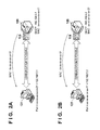
- Figs. 2A and 2B are views for explaining the notification of a key MAC address in this embodiment.
- the image forming apparatus 100 physically includes the network interfaces 115 and 118.
- the network interface 115 is a wired network interface
- the network interface 118 is a wireless network interface.
- the network interface 115 has a MAC address "xx-xx-xx-xx-01”
- the network interface 118 has a MAC address "xx-xx-xx-xx-xx-02”.
- a DHCP Dynamic Host Configuration Protocol
- the DHCP allocates an IP address "192.168.0.2" when using the network interface 118.
- the PC 121 installs a printer driver corresponding to the image forming apparatus 100 as a printer.
- the PC 121 inquires of the image forming apparatus 100 about information necessary to communicate with the image forming apparatus 100.
- the necessary information herein mentioned includes the MAC address of a presently effective network interface of the image forming apparatus 100, an IP address allocated to the MAC address, and a key MAC address.
- the key MAC address is a MAC address required for the PC 121 to track the IP address of the image forming apparatus 100 in Figs. 1 , 2A, and 2B . That is, the key MAC address is a MAC address that functions as a key.
- the image forming apparatus 100 includes a plurality of network interfaces, the MAC address of one of these network interfaces can be set as the key MAC address.
- the notification of the key MAC address of the image forming apparatus 100 will be explained below with reference to Figs. 2A and 2B .
- the presently effective network interface of the image forming apparatus 100 is the network interface 115.
- the image forming apparatus 100 has set the MAC address of the network interface 115 as the key MAC address.
- the PC 121 shown in Fig. 2A inquires of the image forming apparatus 100 about information necessary to communicate with the image forming apparatus 100.
- the image forming apparatus 100 notifies the PC 121 of the MAC address "xx-xx-xx-xx-xx-01" of the network interface 115, the IP address "192.168.0.1", and the key MAC address "xx-xx-xx-xx-xx-01".
- the PC 121 can communicate with the image forming apparatus 100 by forming a port by using the key MAC address and IP address notified from the image forming apparatus 100.
- the image forming apparatus 100 switches from the network interface 115 to the network interface 118 in this state. This is equivalent to a case in which the image forming apparatus 100 switches from the connection to the wired network to the connection to the wireless network.
- the PC 121 installs the printer driver of the image forming apparatus 100 and inquires of the image forming apparatus 100 about information necessary to communicate with it. As shown in Fig. 2B , the image forming apparatus 100 notifies the PC 121 of the MAC address "xx-xx-xx-xx-xx-02" of the network interface 118, the IP address "192.168.0.2", and the key MAC address "xx-xx-xx-xx-xx-01". After that, the PC 121 can communicate with the image forming apparatus 100 by forming a port by using the key MAC address and IP address notified from the image forming apparatus 100.
- an external apparatus is notified of a MAC address always unique to the IP address in order to track it.
- the external apparatus PC 121 can reliably track the dynamically changeable IP address by using a DHCP or the like, based on the key MAC address notified from the image forming apparatus 100.
- Fig. 3 is a view showing the procedure of an IP address automatic tracking process in this embodiment. Processing on the side of the PC 121 shown in Fig. 3 is executed by, for example, the CPU of the PC 121. Also, processing on the side of the image forming apparatus 100 shown in Fig. 3 is executed by, for example, the CPU 102 of the image forming apparatus 100.
- step S301 the CPU of the PC 121 installs the driver of the image forming apparatus 100 in the PC 121.
- This driver is, for example, a printer driver.
- This processing in step S301 allows the PC 121 to use a function (for example, a printer function) of the image forming apparatus 100.
- step S302 the CPU of the PC 121 inquires of the image forming apparatus 100 about apparatus basic information for communicating with the image forming apparatus 100 across the network 120. This is equivalent to the processing explained above with reference to Figs. 2A and 2B .
- the apparatus basic information includes the MAC address (also called the device MAC address) of a presently effective network interface of the image forming apparatus 100, the above-mentioned key MAC address, and a presently allocated IP address.
- step S303 the CPU of the PC 121 transmits, to the image forming apparatus 100, a request packet for requesting the aforementioned apparatus basic information.
- step S304 the CPU 102 of the image forming apparatus 100 notifies the PC 121 of the MAC address of the presently effective network interface, the key MAC address (key data), and the IP address presently allocated to the image forming apparatus 100.
- step S305 the CPU of the PC 121 forms a port for communicating with the image forming apparatus 100 across the network 120, by using the apparatus basic information obtained from the image forming apparatus 100.
- the MAC address of the presently effective network interface is "xx-xx-xx-xx-xx-01”
- the key MAC address of the image forming apparatus 100 is "xx-xx-xx-xx-xx-01”
- the IP address presently allocated to the image forming apparatus 100 is "192.168.0.1”.
- the CPU of the PC 121 transmits request packets (broadcast packets) to the image forming apparatus 100 at a predetermined arbitrary time interval in steps S306 and S309, in order to detect (track) the change in IP address. More specifically, the CPU of the PC 121 transmits request packets in steps S307 and S310 based on the key MAC address obtained in step S302, thereby requesting the notification of the IP address. In steps S308 and S311, the CPU 102 of the image forming apparatus 100 having the requested key MAC address notifies the PC 121 of the key MAC address and presently allocated IP address in response to the requests in steps S307 and S310.
- step S313 the CPU of the PC 121 transmits request packets to the image forming apparatus 100 at a predetermined arbitrary time interval in order to detect the change in IP address, as in steps S306 and S309. More specifically, in step S314, the CPU of the PC 121 transmits a request packet based on the key MAC address obtained in step S302, thereby requesting the notification of the IP address. In step S315, the CPU 102 of the image forming apparatus 100 having the requested key MAC address notifies the PC 121 of the key MAC address and the presently allocated IP address "192.168.0.2", in response to the request in step S314.
- step S316 Assume that the network interfaces of the image forming apparatus 100 having the key MAC address "xx-xx-xx-xx-xx-01" are switched in step S316. This is a case in which the user changes the connections of the image forming apparatus 100 from the wired network to the wireless network. In this embodiment, the IP address is further changed to "192.168.0.3" when the network interfaces are switched.
- step S317 the CPU of the PC 121 transmits request packets to the image forming apparatus 100 at a predetermined arbitrary time interval in order to detect the change in IP address, as in steps S306 and S309. More specifically, in step S318, the CPU of the PC 121 transmits a request packet based on the key MAC address obtained in step S302, thereby requesting the notification of the IP address.
- step S319 the CPU 102 of the image forming apparatus 100 having the requested key MAC address notifies the PC 121 of the key MAC address and the presently allocated IP address "192.168.0.3", in response to the request in step S318.
- the PC 121 can track the IP address without detecting the change in MAC address of the image forming apparatus 100. Consequently, even when the MAC address of the image forming apparatus 100 is changed, it is unnecessary to obtain the apparatus basic information by installing the driver of the image forming apparatus 100.
- the key MAC address is fixedly set as the MAC address of a given network interface of the image forming apparatus 100.
- the MAC address of a network interface designated by the user is set as the key MAC address.
- Fig. 4 is a flowchart showing the procedure of key MAC address setting in this embodiment. This process shown in Fig. 4 is executed by, for example, the CPU 102 of the image forming apparatus 100.
- the CPU 102 determines whether a plurality of network interfaces are installed in the image forming apparatus 100. If it is determined that only one network interface is installed, the CPU 102 sets the MAC address (device MAC address) of the network interface as the key MAC address in step S402, and terminates the process shown in Fig. 4 .
- step S403 the CPU 102 allows the user to select a network interface whose MAC address is to be used as the key MAC address.
- the CPU 102 causes the operation panel 110 to display a list of the MAC addresses of the network interfaces as a selection screen, and accepts a user's selection on the selection screen as the key MAC address. Then, the CPU 102 determines whether a user's selection is accepted.
- the CPU 102 sets the MAC address of the network interface selected by the user as the key MAC address in step S404. On the other hand, if it is determined that no user's selection is accepted, the process advances to step S405, and the CPU 102 selects a preset default MAC address as the key MAC address. For example, if the user has not selected the MAC address of any network interface, the MAC address of one of the network interfaces is selected as the key MAC address.
- aspects of the present invention can also be realized by a computer of a system or apparatus (or devices such as a CPU or MPU) that reads out and executes a program recorded on a memory device to perform the functions of the above-described embodiment(s), and by a method, the steps of which are performed by a computer of a system or apparatus by, for example, reading out and executing a program recorded on a memory device to perform the functions of the above-described embodiment(s).
- the program is provided to the computer for example via a network or from a recording medium of various types serving as the memory device (for example, computer-readable medium).
- MAC addresses a MAC address to which an IP address is to be allocated is set, and key data for tracking an IP address corresponding to the image forming apparatus is set. An external apparatus is notified of the set MAC address and set key data.
Landscapes
- Engineering & Computer Science (AREA)
- Computer Networks & Wireless Communication (AREA)
- Signal Processing (AREA)
- General Engineering & Computer Science (AREA)
- Theoretical Computer Science (AREA)
- Computer Security & Cryptography (AREA)
- Multimedia (AREA)
- Human Computer Interaction (AREA)
- Physics & Mathematics (AREA)
- General Physics & Mathematics (AREA)
- Small-Scale Networks (AREA)
Abstract
Among a plurality of MAC addresses, a MAC address to which an IP address is to be allocated is set, and key data for tracking an IP address corresponding to the image forming apparatus is set. An external apparatus is notified of the set MAC address and set key data.
Description
- The present invention relates to an image forming apparatus for setting a MAC address, an address setting method, and a storage medium storing a program.
- When an image forming apparatus such as a printer equipped with a network interface is used across a network, a DHCP or the like allocates an IP address to the MAC address of the apparatus. An information processing apparatus such as a PC that controls the image forming apparatus can track the dynamically changeable IP address of the image forming apparatus based on the MAC address. Therefore, even when the IP address changes because the image forming apparatus is restarted or the effective period of the IP address has expired, the information processing apparatus can automatically track the IP address of the image forming apparatus.
- As wireless network apparatuses increase in number in recent years, many image forming apparatuses include a plurality of network interfaces such as a wired network interface and wireless network interface. In an image forming apparatus like this, the network interfaces are switched in some cases. An example is a case in which the image information apparatus is initialized by using the wired network interface but operated by using the wireless network interface after that. Another example is a case in which an error occurs in a wireless access point while the image forming apparatus is operated by using the wireless network interface and the apparatus is kept operated by switching to the wired network interface. A still another example is a case in which the form of connection to a network is physically changed by changing the installation location of the image forming apparatus.
- The plurality of network interfaces of the image forming apparatus have unique MAC addresses, respectively. If the network interfaces are switched as described above, therefore, the MAC addresses also change. Accordingly, an external apparatus cannot track the IP address of the image forming apparatus based on its MAC address, and cannot communicate with the image forming apparatus any longer.
- Japanese Patent Laid-Open No.
2002-51068 2002-51068 - In Japanese Patent Laid-Open No.
2002-51068 - An aspect of the present invention is to eliminate the above-mentioned problems with the conventional technology. The present invention provides an image forming apparatus that uniquely sets a MAC address for tracking an IP address, an address setting method, and a storage medium storing a program.
- The present invention in its first aspect provides an image forming apparatus as specified in
claims 1 to 5. - The present invention in its second aspect provides an address setting method as specified in claim 6.
- The present invention in its third aspect provides a computer-readable storage medium as specified in claim 7.
- In the present invention, a MAC address for tracking an IP address can uniquely be set.
- Further features of the present invention will become apparent from the following description of exemplary embodiments with reference to the attached drawings.
-
Fig. 1 is a block diagram showing the hardware configuration of an image forming apparatus; -
Figs. 2A and 2B are views for explaining the notification of the key MAC address of the image forming apparatus; -
Fig. 3 is a flowchart showing the procedure of an IP address automatic tracking process; and -
Fig. 4 is a flowchart showing the procedure of a key MAC address selecting process. - Preferred embodiments of the present invention will now be described hereinafter in detail, with reference to the accompanying drawings. It is to be understood that the following embodiments are not intended to limit the claims of the present invention, and that not all of the combinations of the aspects that are described according to the following embodiments are necessarily required with respect to the means to solve the problems according to the present invention. Note that the same reference numerals denote the same constituent elements, and a repetitive explanation thereof will be omitted.
-
Fig. 1 is a block diagram showing the hardware configuration of animage forming apparatus 100 of an embodiment according to the present invention. Referring toFig. 1 , arrows between blocks indicate the flows of data or instructions. In this embodiment, a process by which the image forming apparatus sets a unique MAC address for a dynamically changeable IP address will be described by taking, as an example, a case in which a PC tracks the IP address of a printer (the image forming apparatus) connected to the PC. However, this process may also be executed on, for example, a PC managed by a server, instead of the image forming apparatus. In the following description, both the image forming apparatus and PC will also generically be referred to as communicating apparatuses. - The
image forming apparatus 100 includes aprinter 107, ascanner 109, anoperation panel 110, a line interface (I/F) 112, and acontroller 101 for controlling them. Thecontroller 101 includes aCPU 102,RAM 103,ROM 104, printer I/F 106, scanner I/F 108, MODEM 111, and network I/Fs system bus 105 so that they can communicate with each other. - The
CPU 102 comprehensively controls the above-mentioned blocks in accordance with various control programs. TheCPU 102 reads out and executes a control program stored in a program area of theROM 104. Alternatively, theCPU 102 executes compressed data stored in the program area of theROM 104 by decompressing and expanding the data into theRAM 103. The various control programs may also be stored in a compressed/uncompressed state in a hard disk drive (HDD) (not shown). The network I/Fs image forming apparatus 100 to a network (LAN) 120. With this arrangement, theCPU 102 can communicate with a host computer (PC) 121 across thenetwork 120. Theimage forming apparatus 100 can connect to awired network 116 and wireless network by using the network I/Fs network 120. It is possible to use, for example, a LAN cable as thewired network 116, and use, for example, a wireless LAN as awireless network 119. The MODEM 111 is connected to apublic network 114 via the line I/F 112. With this arrangement, theCPU 102 can communicate with, for example, another image forming apparatus, a facsimile apparatus, or a telephone set (none of them is shown). The line I/F 112 andpublic network 114 are connected by atelephone line 113 or the like. - The printer I/F 106 functions as an interface for outputting an image signal to the printer 107 (a printer engine). The scanner I/F 108 functions as an interface for receiving a scanned image signal from the scanner 109 (a scanner engine). With this arrangement, the
CPU 102 can process an input image signal from the scanner I/F 108, and output the processed image signal as a printing image signal to the printer I/F 106. TheCPU 102 displays characters and symbols on a display unit of theoperation panel 110 by using font information stored in a font area (font ROM) of theROM 104, and accepts instructions from the user via theoperation panel 110. Also, theCPU 102 stores, for example, apparatus information of theimage forming apparatus 100, user's telephone directory information, and department management information in a data area (data ROM) of theROM 104, and reads out and updates these pieces of information as needed. Although thescanner 109 andprinter 107 are formed inside theimage forming apparatus 100 inFig. 1 , one or both of these units may also be formed outside. -
Figs. 2A and 2B are views for explaining the notification of a key MAC address in this embodiment. Theimage forming apparatus 100 physically includes thenetwork interfaces network interface 115 is a wired network interface, and thenetwork interface 118 is a wireless network interface. Also, thenetwork interface 115 has a MAC address "xx-xx-xx-xx-xx-01", and thenetwork interface 118 has a MAC address "xx-xx-xx-xx-xx-02". Assume that a DHCP (Dynamic Host Configuration Protocol) allocates an IP address "192.168.0.1" when using thenetwork interface 115. Assume also that the DHCP allocates an IP address "192.168.0.2" when using thenetwork interface 118. - For example, the
PC 121 installs a printer driver corresponding to theimage forming apparatus 100 as a printer. In this case, thePC 121 inquires of theimage forming apparatus 100 about information necessary to communicate with theimage forming apparatus 100. The necessary information herein mentioned includes the MAC address of a presently effective network interface of theimage forming apparatus 100, an IP address allocated to the MAC address, and a key MAC address. The key MAC address is a MAC address required for thePC 121 to track the IP address of theimage forming apparatus 100 inFigs. 1 ,2A, and 2B . That is, the key MAC address is a MAC address that functions as a key. When theimage forming apparatus 100 includes a plurality of network interfaces, the MAC address of one of these network interfaces can be set as the key MAC address. - The notification of the key MAC address of the
image forming apparatus 100 will be explained below with reference toFigs. 2A and 2B . First, assume that the presently effective network interface of theimage forming apparatus 100 is thenetwork interface 115. Second, assume that theimage forming apparatus 100 has set the MAC address of thenetwork interface 115 as the key MAC address. - The
PC 121 shown inFig. 2A inquires of theimage forming apparatus 100 about information necessary to communicate with theimage forming apparatus 100. Theimage forming apparatus 100 notifies thePC 121 of the MAC address "xx-xx-xx-xx-xx-01" of thenetwork interface 115, the IP address "192.168.0.1", and the key MAC address "xx-xx-xx-xx-xx-01". After that, thePC 121 can communicate with theimage forming apparatus 100 by forming a port by using the key MAC address and IP address notified from theimage forming apparatus 100. - Assume that the
image forming apparatus 100 switches from thenetwork interface 115 to thenetwork interface 118 in this state. This is equivalent to a case in which theimage forming apparatus 100 switches from the connection to the wired network to the connection to the wireless network. Assume that thePC 121 installs the printer driver of theimage forming apparatus 100 and inquires of theimage forming apparatus 100 about information necessary to communicate with it. As shown inFig. 2B , theimage forming apparatus 100 notifies thePC 121 of the MAC address "xx-xx-xx-xx-xx-02" of thenetwork interface 118, the IP address "192.168.0.2", and the key MAC address "xx-xx-xx-xx-xx-01". After that, thePC 121 can communicate with theimage forming apparatus 100 by forming a port by using the key MAC address and IP address notified from theimage forming apparatus 100. - In this embodiment as described above, even when the
image forming apparatus 100 has a plurality of MAC addresses, an external apparatus is notified of a MAC address always unique to the IP address in order to track it. With this arrangement, the external apparatus (PC 121) can reliably track the dynamically changeable IP address by using a DHCP or the like, based on the key MAC address notified from theimage forming apparatus 100. -
Fig. 3 is a view showing the procedure of an IP address automatic tracking process in this embodiment. Processing on the side of thePC 121 shown inFig. 3 is executed by, for example, the CPU of thePC 121. Also, processing on the side of theimage forming apparatus 100 shown inFig. 3 is executed by, for example, theCPU 102 of theimage forming apparatus 100. - First, in step S301, the CPU of the
PC 121 installs the driver of theimage forming apparatus 100 in thePC 121. This driver is, for example, a printer driver. This processing in step S301 allows thePC 121 to use a function (for example, a printer function) of theimage forming apparatus 100. In step S302, the CPU of thePC 121 inquires of theimage forming apparatus 100 about apparatus basic information for communicating with theimage forming apparatus 100 across thenetwork 120. This is equivalent to the processing explained above with reference toFigs. 2A and 2B . The apparatus basic information includes the MAC address (also called the device MAC address) of a presently effective network interface of theimage forming apparatus 100, the above-mentioned key MAC address, and a presently allocated IP address. - In step S303, the CPU of the
PC 121 transmits, to theimage forming apparatus 100, a request packet for requesting the aforementioned apparatus basic information. In step S304, theCPU 102 of theimage forming apparatus 100 notifies thePC 121 of the MAC address of the presently effective network interface, the key MAC address (key data), and the IP address presently allocated to theimage forming apparatus 100. In step S305, the CPU of thePC 121 forms a port for communicating with theimage forming apparatus 100 across thenetwork 120, by using the apparatus basic information obtained from theimage forming apparatus 100. In this embodiment, the MAC address of the presently effective network interface is "xx-xx-xx-xx-xx-01", the key MAC address of theimage forming apparatus 100 is "xx-xx-xx-xx-xx-01", and the IP address presently allocated to theimage forming apparatus 100 is "192.168.0.1". - After forming the port in step S305, the CPU of the
PC 121 transmits request packets (broadcast packets) to theimage forming apparatus 100 at a predetermined arbitrary time interval in steps S306 and S309, in order to detect (track) the change in IP address. More specifically, the CPU of thePC 121 transmits request packets in steps S307 and S310 based on the key MAC address obtained in step S302, thereby requesting the notification of the IP address. In steps S308 and S311, theCPU 102 of theimage forming apparatus 100 having the requested key MAC address notifies thePC 121 of the key MAC address and presently allocated IP address in response to the requests in steps S307 and S310. - Assume that the
image forming apparatus 100 having the key MAC address "xx-xx-xx-xx-xx-01" is restarted by a user's operation or the like in step S312. In this embodiment, an IP address automatically obtained by the DHCP or the like upon restart is changed to "192.168.0.2". - In step S313, the CPU of the
PC 121 transmits request packets to theimage forming apparatus 100 at a predetermined arbitrary time interval in order to detect the change in IP address, as in steps S306 and S309. More specifically, in step S314, the CPU of thePC 121 transmits a request packet based on the key MAC address obtained in step S302, thereby requesting the notification of the IP address. In step S315, theCPU 102 of theimage forming apparatus 100 having the requested key MAC address notifies thePC 121 of the key MAC address and the presently allocated IP address "192.168.0.2", in response to the request in step S314. - Assume that the network interfaces of the
image forming apparatus 100 having the key MAC address "xx-xx-xx-xx-xx-01" are switched in step S316. This is a case in which the user changes the connections of theimage forming apparatus 100 from the wired network to the wireless network. In this embodiment, the IP address is further changed to "192.168.0.3" when the network interfaces are switched. - In step S317, the CPU of the
PC 121 transmits request packets to theimage forming apparatus 100 at a predetermined arbitrary time interval in order to detect the change in IP address, as in steps S306 and S309. More specifically, in step S318, the CPU of thePC 121 transmits a request packet based on the key MAC address obtained in step S302, thereby requesting the notification of the IP address. In step S319, theCPU 102 of theimage forming apparatus 100 having the requested key MAC address notifies thePC 121 of the key MAC address and the presently allocated IP address "192.168.0.3", in response to the request in step S318. - In this embodiment as described above, the
PC 121 can track the IP address without detecting the change in MAC address of theimage forming apparatus 100. Consequently, even when the MAC address of theimage forming apparatus 100 is changed, it is unnecessary to obtain the apparatus basic information by installing the driver of theimage forming apparatus 100. - In the first embodiment, the key MAC address is fixedly set as the MAC address of a given network interface of the
image forming apparatus 100. In this embodiment, when theimage forming apparatus 100 includes a plurality of network interfaces, the MAC address of a network interface designated by the user is set as the key MAC address. -
Fig. 4 is a flowchart showing the procedure of key MAC address setting in this embodiment. This process shown inFig. 4 is executed by, for example, theCPU 102 of theimage forming apparatus 100. In step S401, theCPU 102 determines whether a plurality of network interfaces are installed in theimage forming apparatus 100. If it is determined that only one network interface is installed, theCPU 102 sets the MAC address (device MAC address) of the network interface as the key MAC address in step S402, and terminates the process shown inFig. 4 . - On the other hand, if it is determined that a plurality of network interfaces are installed, the process advances to step S403, and the
CPU 102 allows the user to select a network interface whose MAC address is to be used as the key MAC address. In this step, theCPU 102 causes theoperation panel 110 to display a list of the MAC addresses of the network interfaces as a selection screen, and accepts a user's selection on the selection screen as the key MAC address. Then, theCPU 102 determines whether a user's selection is accepted. - If it is determined that a user's selection is accepted, the
CPU 102 sets the MAC address of the network interface selected by the user as the key MAC address in step S404. On the other hand, if it is determined that no user's selection is accepted, the process advances to step S405, and theCPU 102 selects a preset default MAC address as the key MAC address. For example, if the user has not selected the MAC address of any network interface, the MAC address of one of the network interfaces is selected as the key MAC address. - Aspects of the present invention can also be realized by a computer of a system or apparatus (or devices such as a CPU or MPU) that reads out and executes a program recorded on a memory device to perform the functions of the above-described embodiment(s), and by a method, the steps of which are performed by a computer of a system or apparatus by, for example, reading out and executing a program recorded on a memory device to perform the functions of the above-described embodiment(s). For this purpose, the program is provided to the computer for example via a network or from a recording medium of various types serving as the memory device (for example, computer-readable medium).
- While the present invention has been described with reference to exemplary embodiments, it is to be understood that the invention is not limited to the disclosed exemplary embodiments. The scope of the following claims is to be accorded the broadest interpretation so as to encompass all such modifications and equivalent structures and functions.
Among a plurality of MAC addresses, a MAC address to which an IP address is to be allocated is set, and key data for tracking an IP address corresponding to the image forming apparatus is set. An external apparatus is notified of the set MAC address and set key data.
Claims (7)
- An image forming apparatus (100) capable of handling a plurality of MAC addresses, comprising:setting means (102) for setting a MAC address of the plurality of MAC addresses to which an IP address is to be allocated, and key data for tracking an IP address corresponding to the image forming apparatus; andnotification means (102) for notifying an external apparatus of the MAC address and the key data set by said setting means.
- The apparatus according to claim 1, wherein the plurality of MAC addresses are respectively allocated to a plurality of network interfaces for connecting the image forming apparatus to a plurality of networks.
- The apparatus according to claim 1, wherein said setting means sets the key data from the plurality of MAC addresses.
- The apparatus according to claim 3, wherein said setting means sets a MAC address selected from the plurality of MAC addresses on a selection screen by a user, as the key data.
- The apparatus according to claim 1, wherein
the image forming apparatus is a printer, and
said notification means notifies the MAC address and the key data in response to a request from the external apparatus, in a case where the external apparatus installs a printer driver of the printer. - An address setting method to be executed in an image forming (100) apparatus having a plurality of MAC addresses, comprising:a setting step of setting a MAC address of the plurality of MAC addresses to which an IP address is to be allocated, and key data for tracking an IP address corresponding to the image forming apparatus; anda notification step of notifying an external apparatus of the MAC address and the key data set in the setting step.
- A computer-readable storage medium storing a program for causing a computer to execute an address setting method to be executed in an image forming apparatus (100) having a plurality of MAC addresses, the method comprising:a setting step of setting a MAC address of the plurality of MAC addresses to which an IP address is to be allocated, and key data for tracking an IP address corresponding to the image forming apparatus; anda notification step of notifying an external apparatus of the MAC address and the key data set in the setting step.
Applications Claiming Priority (1)
| Application Number | Priority Date | Filing Date | Title |
|---|---|---|---|
| JP2012067979A JP2013201555A (en) | 2012-03-23 | 2012-03-23 | Communication apparatus, address setting method, and program |
Publications (1)
| Publication Number | Publication Date |
|---|---|
| EP2642743A2 true EP2642743A2 (en) | 2013-09-25 |
Family
ID=47877779
Family Applications (1)
| Application Number | Title | Priority Date | Filing Date |
|---|---|---|---|
| EP13156566.5A Withdrawn EP2642743A2 (en) | 2012-03-23 | 2013-02-25 | Image forming apparatus, address setting method, and storage medium storing program |
Country Status (4)
| Country | Link |
|---|---|
| US (1) | US20130250355A1 (en) |
| EP (1) | EP2642743A2 (en) |
| JP (1) | JP2013201555A (en) |
| KR (1) | KR20130108130A (en) |
Cited By (1)
| Publication number | Priority date | Publication date | Assignee | Title |
|---|---|---|---|---|
| CN112399920A (en) * | 2018-08-30 | 2021-02-23 | 惠普发展公司,有限责任合伙企业 | Verification mechanism |
Families Citing this family (2)
| Publication number | Priority date | Publication date | Assignee | Title |
|---|---|---|---|---|
| US10855809B2 (en) * | 2016-02-26 | 2020-12-01 | Avery Dennison Retail Information Services, Llc | Printer with dual media access control interfaces and uninterrupted interface change |
| JP7027084B2 (en) | 2017-09-14 | 2022-03-01 | キヤノン株式会社 | Information processing equipment, its control method, and programs |
Citations (1)
| Publication number | Priority date | Publication date | Assignee | Title |
|---|---|---|---|---|
| JP2002051068A (en) | 2000-08-04 | 2002-02-15 | Nec Corp | Duplex network system and mac address matching method for duplex system |
Family Cites Families (2)
| Publication number | Priority date | Publication date | Assignee | Title |
|---|---|---|---|---|
| US20060153167A1 (en) * | 2004-11-19 | 2006-07-13 | Schunemann Alan J | Computer tracking and locking |
| KR101496650B1 (en) * | 2009-10-01 | 2015-02-27 | 삼성전자주식회사 | Image forming apparatus for supporting wired network interface and wireless network interface and method for connecting network in same apparatus |
-
2012
- 2012-03-23 JP JP2012067979A patent/JP2013201555A/en active Pending
-
2013
- 2013-02-21 US US13/772,948 patent/US20130250355A1/en not_active Abandoned
- 2013-02-25 EP EP13156566.5A patent/EP2642743A2/en not_active Withdrawn
- 2013-03-14 KR KR1020130027275A patent/KR20130108130A/en not_active Application Discontinuation
Patent Citations (1)
| Publication number | Priority date | Publication date | Assignee | Title |
|---|---|---|---|---|
| JP2002051068A (en) | 2000-08-04 | 2002-02-15 | Nec Corp | Duplex network system and mac address matching method for duplex system |
Cited By (3)
| Publication number | Priority date | Publication date | Assignee | Title |
|---|---|---|---|---|
| CN112399920A (en) * | 2018-08-30 | 2021-02-23 | 惠普发展公司,有限责任合伙企业 | Verification mechanism |
| US11364725B2 (en) | 2018-08-30 | 2022-06-21 | Hewlett-Packard Development Company, L.P. | Authentication mechanisms |
| CN112399920B (en) * | 2018-08-30 | 2023-01-10 | 惠普发展公司,有限责任合伙企业 | Verification mechanism |
Also Published As
| Publication number | Publication date |
|---|---|
| US20130250355A1 (en) | 2013-09-26 |
| JP2013201555A (en) | 2013-10-03 |
| KR20130108130A (en) | 2013-10-02 |
Similar Documents
| Publication | Publication Date | Title |
|---|---|---|
| US8896874B2 (en) | Communication apparatus and control method thereof, communication system, and storage medium | |
| US8769064B2 (en) | System using wired interface to configure wireless connection between host and image forming device | |
| JP6222950B2 (en) | Printing apparatus, control method thereof, and program | |
| JP2009505127A (en) | Display system, module and method | |
| US10382923B2 (en) | Communication apparatus capable of preventing data erroneous transmission, control method therefor, and storage medium storing control program therefor | |
| JP2008186238A (en) | Power source management method, management system, client server system, displaying method of power source control screen, and displaying system | |
| US11455133B2 (en) | Information processing apparatus including setting screen, control method therefor, and storage medium | |
| US20190021035A1 (en) | Information processing apparatus capable of easily identify line to be used, control method therefor, and storage medium | |
| EP2642743A2 (en) | Image forming apparatus, address setting method, and storage medium storing program | |
| EP2958346A1 (en) | Information processing apparatus, information processing method and recording medium | |
| US8761615B2 (en) | Image forming apparatus, host device and print controlling method | |
| US20190132457A1 (en) | Information processing apparatus equipped with communication functions, control method therefor, and storage medium | |
| KR102001486B1 (en) | Image forming apparatus that carries out communication with multiple external apparatuses, control method for the image forming apparatus, and storage medium | |
| JP6260025B2 (en) | Image forming system and device setting method | |
| US10574837B2 (en) | Information processing apparatus for data communication with external apparatus and control method for the same, and storage medium | |
| US10834046B2 (en) | Information processing apparatus with communication lines, control method therefor, and storage medium storing control program therefor | |
| US11784966B2 (en) | Information processing device, control method for information processing device, and recording medium, that suppress duplication of a device name in a DNS server | |
| JP2013117783A (en) | Image display unit | |
| CN109257452B (en) | Information processing apparatus, control method thereof, and storage medium | |
| JP2011159057A (en) | Data communication system | |
| US9350891B2 (en) | Image forming system, image forming apparatus, and non-transitory computer readable recording medium storing a setup program | |
| JP2002091733A (en) | Printing system and re-output control method therefor | |
| US9083828B2 (en) | Communication apparatus that carries out communication with external apparatus, control method therefor, and storage medium | |
| JP2006244004A (en) | Electronic equipment and setting information acquisition method | |
| JP2009020737A (en) | Equipment management system, equipment management program and recording medium |
Legal Events
| Date | Code | Title | Description |
|---|---|---|---|
| PUAI | Public reference made under article 153(3) epc to a published international application that has entered the european phase |
Free format text: ORIGINAL CODE: 0009012 |
|
| AK | Designated contracting states |
Kind code of ref document: A2 Designated state(s): AL AT BE BG CH CY CZ DE DK EE ES FI FR GB GR HR HU IE IS IT LI LT LU LV MC MK MT NL NO PL PT RO RS SE SI SK SM TR |
|
| AX | Request for extension of the european patent |
Extension state: BA ME |
|
| STAA | Information on the status of an ep patent application or granted ep patent |
Free format text: STATUS: THE APPLICATION HAS BEEN WITHDRAWN |
|
| 18W | Application withdrawn |
Effective date: 20150216 |