EP2642710A1 - Verfahren und vorrichtung zur ressourcenzuweisung - Google Patents
Verfahren und vorrichtung zur ressourcenzuweisung Download PDFInfo
- Publication number
- EP2642710A1 EP2642710A1 EP11841326.9A EP11841326A EP2642710A1 EP 2642710 A1 EP2642710 A1 EP 2642710A1 EP 11841326 A EP11841326 A EP 11841326A EP 2642710 A1 EP2642710 A1 EP 2642710A1
- Authority
- EP
- European Patent Office
- Prior art keywords
- bands
- sub
- interference
- cell
- determined
- Prior art date
- Legal status (The legal status is an assumption and is not a legal conclusion. Google has not performed a legal analysis and makes no representation as to the accuracy of the status listed.)
- Granted
Links
- 238000000034 method Methods 0.000 title claims abstract description 33
- 238000013468 resource allocation Methods 0.000 title claims abstract description 20
- 230000001174 ascending effect Effects 0.000 claims description 4
- 238000012163 sequencing technique Methods 0.000 claims description 3
- 101150071746 Pbsn gene Proteins 0.000 claims 2
- 230000005540 biological transmission Effects 0.000 abstract description 13
- 239000002699 waste material Substances 0.000 abstract description 3
- 238000004891 communication Methods 0.000 abstract description 2
- 230000003247 decreasing effect Effects 0.000 abstract 1
- 230000008054 signal transmission Effects 0.000 abstract 1
- 238000010586 diagram Methods 0.000 description 24
- 238000004590 computer program Methods 0.000 description 14
- 238000012545 processing Methods 0.000 description 10
- 230000006855 networking Effects 0.000 description 9
- 238000012986 modification Methods 0.000 description 7
- 230000004048 modification Effects 0.000 description 7
- 230000006870 function Effects 0.000 description 6
- 238000012423 maintenance Methods 0.000 description 2
- 230000003287 optical effect Effects 0.000 description 2
- 230000008569 process Effects 0.000 description 2
- 230000003321 amplification Effects 0.000 description 1
- 238000007429 general method Methods 0.000 description 1
- 230000006872 improvement Effects 0.000 description 1
- 230000007774 longterm Effects 0.000 description 1
- 238000003199 nucleic acid amplification method Methods 0.000 description 1
- 230000003068 static effect Effects 0.000 description 1
- 230000001360 synchronised effect Effects 0.000 description 1
Images


Classifications
-
- H—ELECTRICITY
- H04—ELECTRIC COMMUNICATION TECHNIQUE
- H04W—WIRELESS COMMUNICATION NETWORKS
- H04W72/00—Local resource management
- H04W72/04—Wireless resource allocation
- H04W72/044—Wireless resource allocation based on the type of the allocated resource
- H04W72/0453—Resources in frequency domain, e.g. a carrier in FDMA
-
- H—ELECTRICITY
- H04—ELECTRIC COMMUNICATION TECHNIQUE
- H04L—TRANSMISSION OF DIGITAL INFORMATION, e.g. TELEGRAPHIC COMMUNICATION
- H04L5/00—Arrangements affording multiple use of the transmission path
- H04L5/003—Arrangements for allocating sub-channels of the transmission path
- H04L5/0058—Allocation criteria
- H04L5/0062—Avoidance of ingress interference, e.g. ham radio channels
-
- H—ELECTRICITY
- H04—ELECTRIC COMMUNICATION TECHNIQUE
- H04L—TRANSMISSION OF DIGITAL INFORMATION, e.g. TELEGRAPHIC COMMUNICATION
- H04L27/00—Modulated-carrier systems
- H04L27/26—Systems using multi-frequency codes
-
- H—ELECTRICITY
- H04—ELECTRIC COMMUNICATION TECHNIQUE
- H04L—TRANSMISSION OF DIGITAL INFORMATION, e.g. TELEGRAPHIC COMMUNICATION
- H04L5/00—Arrangements affording multiple use of the transmission path
- H04L5/003—Arrangements for allocating sub-channels of the transmission path
- H04L5/0044—Arrangements for allocating sub-channels of the transmission path allocation of payload
Definitions
- the present invention relates to the technical field of wireless communication and particularly to a method and device for resource allocation.
- a general method for lowering inter-cell interference is to obviate interference by using an inter-cell interference coordination method.
- a general principle thereof is to limit the use of resources in an inter-cell coordination way, where available time and frequency resources are limited or transmission power is limited over specific time and frequency resources.
- a simple implementation method is to perform static inter-cell interference coordination, as illustrated in Fig.1 , in which there are two schemes:
- the entire system bandwidth is divided into four segments, where only one of three sub-bands A is available to each cell at the edge of adjacent cells, and only sub-band B is available at the center of the cell. It can be seen that at this time the entire system bandwidth can not actually be used by any cell for working, that is, for any cell, there are idle sub-bands in which no signal can be transmitted, but hardware devices of the cell still support the cell to work throughout the system bandwidth (i.e., 3A+B), thus resulting in costs of the hardware devices and useless power consumption.
- the entire system bandwidth is divided into three segments, where only one of three sub-bands A is available to each cell at the edge of adjacent cells, and only the entire system bandwidth is available at the center of the cell.
- transmission power at the center of the cell need be lowered in order to alleviate interference of a user at the center of the cell to another user outside the cell. It can be seen that although at this time the entire frequency band can be used by any cell for working, transmission at full power can not be performed, thus reducing power amplification efficiency.
- inter-cell interference coordination schemes are applicable only to physical downlink shared channels and physical uplink shared channels, and for broadcast channels, synchronization channels, control channels and other common channels in LTE, since their occupied time and frequency resources are relatively fixed, interference can not be obviated by the simple resource coordination way.
- the existing inter-cell interference coordination schemes can lower inter-cell interference of shared channels effectively, they can not be applicable to transmission of broadcast, synchronization, control channels and other common channels; and when applied to shared channels, there are problems of wasting hardware resources in a base station and increasing useless power consumption. Furthermore, costs of network deployment are also increased.
- lowering interference in the inter-cell interference coordination schemes at present typically results in a low resource utilization rate of the cell or a limitation on the transmission power, and consequently a waste of hardware resources in the base station and an increase in power consumption.
- Embodiments of the invention provide a method and device for resource allocation, so as to address the problems in the prior art that lowering interference in the inter-cell interference coordination schemes typically results in the low resource utilization rate of the cell or the limitation on the transmission power and consequently the waste of hardware resources in the base station and the increase in the power consumption.
- An embodiment of the invention provides a method for resource allocation, which includes:
- An embodiment of the invention provides a device for resource allocation, which includes:
- Fig.1 is a schematic diagram of inter-cell interference coordination in the prior art
- Fig.2 is a schematic flow chart of a method for resource allocation according to an embodiment of the invention.
- Fig.3 is a schematic structural diagram of a device for resource allocation according to an embodiment of the invention.
- Fig.4 is a schematic diagram of allocation of sub-bands according to an embodiment of the invention.
- Fig.5 is a schematic diagram of allocation of a downlink common channel according to an embodiment of the invention.
- Fig.6 is a schematic diagram of allocation of an uplink common channel according to an embodiment of the invention.
- Fig.7 is a schematic diagram of first carrier bandwidth allocation according to an embodiment of the invention.
- Fig.8 is a schematic diagram of second carrier bandwidth allocation according to an embodiment of the invention.
- Fig.9 is a schematic diagram of third carrier bandwidth allocation according to an embodiment of the invention.
- Fig.10 is a schematic diagram of fourth carrier bandwidth allocation according to an embodiment of the invention.
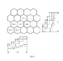
- Fig.11 is a schematic diagram of cell deployment of two sub-bands according to an embodiment of the invention.
- Fig.12 is a schematic diagram of cell deployment of three sub-bands according to an embodiment of the invention.
- Fig.13 is a schematic diagram of cell deployment of four sub-bands according to an embodiment of the invention.
- At least two sub-bands are determined in a carrier bandwidth, where central frequency points of respective sub-bands are different, there is an overlapping area in the frequency domain between at least two sub-bands of all the sub-bands, and the sum of the bandwidth of the overlapping area and the bandwidth of a non-overlapping area is no larger than the carrier bandwidth.
- carrier bandwidth refers to the entire bandwidth available to an operator.
- the embodiments of the invention can be applied to a TD-LTE system, and can also be applied to an LTE-Frequency Division Duplex (FDD) system, an LTE-Advance system and the like.
- FDD Frequency Division Duplex
- the embodiments of the invention perform network deployment using a base station device in support of a smaller system bandwidth, for example, the carrier bandwidth is 20 MHz, while the system bandwidth supported by the base station device is 10 MHz, and thus adjacent cells should have their central frequency points skipped and have a specific overlapping width which is set as required.
- the carrier bandwidth is 20 MHz
- the system bandwidth supported by the base station device is 10 MHz
- adjacent cells should have their central frequency points skipped and have a specific overlapping width which is set as required.
- Fig.4 and by way of an example where a cell is deployed as three sectors together with a carrier bandwidth of 20 MHz and a system bandwidth of a base station device of 10 MHz, it can be seen that different cells are subject to lowered interference as compared with the network deployment using a base station device with a system bandwidth of 20 MHz uniformly.
- interference is lowered to 1/3 of that under the condition of same-frequency networking (that is, all of three cells support the system bandwidth of 20 MHz and their central frequency points coincide); and in the frequency band B, interference is lowered to 2/3 of that under the condition of same-frequency networking.
- the frequency band A As an example, it is assumed that there are further cells 4, 5 and 6 present, where sub-bands allocated to the cell 4 is the frequency bands A+B, sub-bands allocated to the cell 5 is the frequency bands B+C, and sub-bands allocated to the cell 6 is the frequency bands C+D, and then for the cell 4, since each cell uses a bandwidth of 20 MHz in the same-frequency networking scheme, that is, the frequency band A is available to each of the cell 1, the cell 2 and the cell 3, the cell 4 will be subject to interference from the cell 1, the cell 2 and the cell 3 in the frequency band A, while with sub-bands offset from each other, the frequency band A is only available to the cell 1, and there is no interference from the cell 2 and the cell 3 in the frequency band A, thus lowering interference to 1/3 of original interference, where the lowering factor is just a relative value because interference particularly further depends upon other factors, e.g., environment, hardware, etc., but the purpose of lowering interference has been achieved as compared with the same-frequency networking scheme.
- interference is lowered to 2/3 of that under the condition of same-frequency networking; and in the frequency band D, interference is lowered to 1/3 of that under the condition of same-frequency networking.
- interference is lowered to 2/3 of that under the condition of same-frequency networking; and in the frequency band C, interference is lowered to 2/3 of that under the condition of same-frequency networking.
- inter-cell interference can be lowered effectively for a Physical Control Format Indication Channel (PCFICH), a Physical Downlink Control Channel (PDCCH) and a Physical Hybrid Automatic Repeat Request (HARQ) Indication Channel (PHICH) occupying the entire system bandwidth.
- PCFICH Physical Control Format Indication Channel
- PDCCH Physical Downlink Control Channel
- HARQ Physical Hybrid Automatic Repeat Request
- PHICH Physical Hybrid Automatic Repeat Request
- their occupied physical resources can be offset from each other in the frequency domain in this way to thereby obviate interference between the common channels effectively.
- a Physical Broadcast Channel PBCH
- PSS Primary Synchronized Signal
- SSS Secondary Synchronization Signal
- PRBs Physical Resource Blocks
- interference is lowered to 1/3 of original interference; and in the frequency band B, interference is lowered to 2/3 of original interference.
- interference is lowered to 2/3 of original interference; and in the frequency band D, interference is lowered to 1/3 of original interference.
- interference is lowered to 2/3 of original interference; and in the frequency band C, interference is lowered to 2/3 of original interference.
- a method for resource allocation includes the following steps:
- Step 201 determining at least two sub-bands in a carrier bandwidth, wherein central frequency points of respective sub-bands are different, and there is an overlapping area in a frequency domain between at least two sub-bands of all sub-bands.
- Step 202 allocating the determined sub-bands to respective cells in a deployment region.
- sub-bands allocated to a cell are taken as a system bandwidth of that cell.
- the carrier bandwidth can be larger than, equal to or smaller than the maximum bandwidth supported by a system, for example, the LTE system supports the maximum bandwidth of 20 MHz, so the carrier bandwidth can be larger than or smaller than or equal to 20 MHz.
- the width of each determined sub-band is preset and preferably equals to the system bandwidth supported by the system.
- system bandwidths supported by the LTE system include 1.4 MHz, 3 MHz, 5 MHz, 10 MHz, 15 MHz and 20 MHz, so the width of each determined sub-band would be equal to one of the above values.
- all or a part of the determined respective sub-bands are identical in width, or any two of the determined sub-bands are different in width. Since a base station is configured according to the size of the system bandwidth, for example, the system bandwidth is 10 MHz and then a base station in support of 10 MHz need be configured, if there are a large number of base stations in support of different bandwidths, then there will be an increase in device type, inconvenience in maintenance and an increase in maintenance cost, so it is preferable that the widths of all the determined sub-bands are identical.
- the number and the widths of the sub-bands can further be determined finally in combination of a specific network throughput demand and an interference condition. For example, a smaller number of sub-bands can be determined and the sub-bands can be wider (that is, more overlaps in the frequency domain) in the case of a higher throughput requirement and lower interference; and a larger number of sub-bands can be determined and the sub-bands can be narrower (that is, less overlaps in the frequency domain) in the case of a lower throughput requirement and serious interference.
- the sub-bands when determining the sub-bands, can be further numbered in a descending or ascending order of central frequency points.
- step 202 when allocating the determined sub-bands to respective cells in a deployment region, sub-bands with consecutive serial numbers are allocated to cells nonadjacent in geographical location.
- the overlapping area can be an area between sub-bands with consecutive serial numbers or an area between sub-bands with nonconsecutive serial numbers. Preferably, it is ensured that there is an overlapping area between at least one pair of sub-bands with consecutive serial numbers.
- the overlapping area is an area between one pair of sub-bands with consecutive serial numbers; and if there are a plurality of overlapping areas, then each overlapping area can be an area between one pair of sub-bands with consecutive serial numbers, or a part of the overlapping areas can be areas between one pair of sub-bands with consecutive serial numbers.
- step 202 that can be further included:
- a base station device consistent with the system bandwidth of the cell is selected to perform network deployment, and the deployed base station transmits and receives signals.
- any cell (referred to as the current cell hereinafter) in the deployment region uses preferentially a frequency band, outside an overlapping area in frequency with other sub-bands, to transmit data, that is, uses preferentially frequency resources unused by the other sub-bands.
- the current cell uses preferentially a frequency band outside an overlapping area with other sub-bands and/or a frequency band unoccupied by a PBCH, a PUCCH and a PRACH to schedule data, thereby further lowering inter-cell interference.
- the current cell uses preferentially a frequency band outside the overlapping area with other sub-bands to schedule data; the current cell uses preferentially a frequency band unoccupied by the PBCH, the PUCCH and the PRACH to schedule data; or the current cell uses preferentially a frequency band outside the overlapping area with other sub-bands and unoccupied by the PBCH, the PUCCH and the PRACH to schedule data.
- step 201 Some specific examples will be given below for the step 201 to further describe the solution of the invention.
- Example 1 the carrier bandwidth is 40 MHz, and three sub-bands are determined with the same width of 20 MHz, where there is an overlapping area in the frequency domain between sub-bands with consecutive serial numbers, as illustrated in Fig.7 .
- interference is lowered to 1/3 of original interference
- Example 2 the carrier bandwidth is 20 MHz, and four sub-bands are determined with different widths, which are 10 MHz, 10 MHz, 5 MHz and 5 MHz respectively, where there is an overlapping area in the frequency domain between sub-bands with consecutive serial numbers, as illustrated in Fig.8 .
- the sub-bands are different in width, and there are different overlapping areas, of 5 MHz and 2.5 MHz respectively, in the frequency domain between sub-bands with consecutive serial numbers.
- Example 3 the carrier bandwidth is 15 MHz, and two sub-bands are determined with the same width of 10 MHz, where there is an overlapping area in the frequency domain between sub-bands with consecutive serial numbers, as illustrated in Fig.9 .
- the sub-bands are identical in width, and there is an overlapping area of 5 MHz in the frequency domain between sub-bands with consecutive serial numbers, the width of each sub-band is 10 MHz, and the total carrier bandwidth is 15 MHz.
- Example 4 the carrier bandwidth is 18 MHz, and three sub-bands are determined with different widths, which are 10 MHz, 10 MHz and 3 MHz respectively, where there is an overlapping area in the frequency domain between the two sub-bands of 10 MHz with a total width of 15 MHz, and there is no overlapping area in the frequency domain between the sub-band of 3 MHz and the sub-band of 10 MHz, as illustrated in Fig.10 .
- the sub-band 1 and the sub-band 2 are identical in width and overlap in the frequency domain by 5 MHz, and the sub-band 3 has no overlapping area with the sub-band 2 and exclusively occupies a bandwidth of 3 MHz.
- the total carrier width is 18 MHz.
- interference is lowered to 1/3 of original interference
- step 202 Some specific examples will be given below for the step 202 to further describe the solution of the invention.
- Example 1 the number of sub-bands is 2, the carrier bandwidth is 15 MHz, the sub-bands are identical in width of 10 MHz, and there is an overlapping area in the frequency domain between sub-bands with consecutive serial numbers, as illustrated in Fig.11 .
- interference is lowered to 1/2 of original interference; and in the frequency band B, interference is not lowered.
- interference is lowered to 1/2 of original interference; and in the frequency band B, interference is not lowered.
- interference is not lowered; and in the frequency band C, interference is lowered to 1/2 of original interference.
- Example 2 the number of sub-bands is 3, the carrier bandwidth is 20 MHz, the sub-bands are identical in width of 10 MHz, and there is an overlapping area in the frequency domain between sub-bands with consecutive serial numbers, as illustrated in Fig. 12 .
- interference is lowered to 1/3 of original interference; and in the frequency band B, interference is lowered to 2/3 of original interference.
- interference is lowered to 2/3 of original interference; and in the frequency band D, interference is lowered to 1/3 of original interference.
- interference is lowered to 2/3 of original interference; and in the frequency band C, interference is lowered to 2/3 of original interference.
- Example 3 the number of sub-bands is 4, the carrier bandwidth is 25 MHz, the sub-bands are identical in width of 10 MHz, and there is an overlapping area in the frequency domain between sub-bands with consecutive serial numbers, as illustrated in Fig.13 .
- the sub-bands configured for the cell are inconsecutive and have a non-overlapping area therebeween; in the second scheme, the sub-bands configured for the cell are consecutive and have an overlapping area therebeween; in the third scheme, the sub-bands configured for the cell are inconsecutive and have an overlapping area therebeween; and in the fourth scheme, the sub-bands configured for the cell are consecutive and have a non-overlapping area therebeween.
- adjacent cells are configured with inconsecutive sub-bands:
- interference is lowered to 1/3 of original interference; and in the frequency band B, interference is lowered to 1/3 of original interference.
- interference is lowered to 1/3 of original interference; and in the frequency band D, interference is lowered to 2/3 of original interference.
- interference is lowered to 1/3 of original interference; and in the frequency band D, interference is lowered to 2/3 of original interference.
- adjacent cells are configured with consecutive sub-bands:
- interference is lowered to 2/3 of original interference; and in the frequency band D, interference is lowered to 1/3 of original interference.
- interference is lowered to 1/3 of original interference; and in the frequency band B, interference is lowered to 2/3 of original interference.
- interference is lowered to 2/3 of original interference; and in the frequency band C, interference is lowered to 2/3 of original interference.
- the third and fourth schemes are similar to the foregoing two schemes, and repeated descriptions thereof will be omitted here.
- an embodiment of the invention further provides a device for resource allocation, and since the device for resource allocation addresses the problems under a similar principle to the method for resource allocation, reference can be made to the implementations of the method for implementations of the device for resource allocation, and a repeated description thereof will be omitted here.
- the device for resource allocation includes a determining module 10 and an allocating module 20.
- the determining module 10 is configured to determine at least two sub-bands in a carrier bandwidth, wherein central frequency points of respective sub-bands are different, and there is an overlapping area in a frequency domain between at least two sub-bands of all sub-bands.
- the allocating module 20 is configured to allocate the determined sub-bands to respective cells in a deployment region, wherein sub-bands allocated to a cell are taken as a system bandwidth of that cell.
- All or a part of the respective sub-bands determined by the determining module 10 are identical in width, or any two of the sub-bands determined by the determining module 10 are different in width.
- the device for resource allocation according to the embodiment of the invention can further include a sequencing module 30.
- the sequencing module 30 is configured to number the sub-bands in a descending or ascending order of their central frequency points.
- the allocating module 20 allocates sub-bands with consecutive serial numbers to cells nonadjacent in geographical location.
- PRBs Physical Resource Blocks
- the device for resource allocation according to the embodiment of the invention can further include a first scheduling module 40.
- the first scheduling module 40 is configured to transmit data in a current cell preferentially in a frequency band outside an overlapping area in frequency with other sub-bands.
- the device can further include a second scheduling module 50.
- the second scheduling module 50 is configured to schedule data in a current cell preferentially in a frequency band outside an overlapping area with other sub-bands and/or in a frequency band unoccupied by a PBCH, a PUCCH and a PRACH.
- the width of each sub-band determined by the determining module 10 is preset.
- the embodiments of the invention can be embodied as a method, a system or a computer program product. Therefore the invention can be embodied in the form of an all-hardware embodiment, an all-software embodiment or an embodiment of software and hardware in combination. Furthermore, the invention can be embodied in the form of a computer program product embodied in one or more computer useable storage mediums (including but not limited to a disk memory, a CD-ROM, an optical memory, etc.) in which computer useable program codes are contained.
- a computer useable storage mediums including but not limited to a disk memory, a CD-ROM, an optical memory, etc.
- These computer program instructions can also be stored into a computer readable memory capable of directing the computer or the other programmable data processing device to operate in a specific manner so that the instructions stored in the computer readable memory create manufactures including instruction means which perform the functions specified in the flow(s) of the flow charts and/or the block(s) of the block diagrams.
- These computer program instructions can also be loaded onto the computer or the other programmable data processing device so that a series of operational steps are performed on the computer or the other programmable data processing device to create a computer implemented process so that the instructions executed on the computer or the other programmable device provide steps for performing the functions specified in the flow(s) of the flow charts and/or the block(s) of the block diagrams.
Landscapes
- Engineering & Computer Science (AREA)
- Signal Processing (AREA)
- Computer Networks & Wireless Communication (AREA)
- Mobile Radio Communication Systems (AREA)
Applications Claiming Priority (2)
| Application Number | Priority Date | Filing Date | Title |
|---|---|---|---|
| CN201010546149.1A CN102469467B (zh) | 2010-11-15 | 2010-11-15 | 一种资源分配的方法和设备 |
| PCT/CN2011/082198 WO2012065538A1 (zh) | 2010-11-15 | 2011-11-15 | 一种资源分配的方法和设备 |
Publications (3)
| Publication Number | Publication Date |
|---|---|
| EP2642710A1 true EP2642710A1 (de) | 2013-09-25 |
| EP2642710A4 EP2642710A4 (de) | 2014-05-14 |
| EP2642710B1 EP2642710B1 (de) | 2015-10-21 |
Family
ID=46072495
Family Applications (1)
| Application Number | Title | Priority Date | Filing Date |
|---|---|---|---|
| EP11841326.9A Active EP2642710B1 (de) | 2010-11-15 | 2011-11-15 | Verfahren und vorrichtung zur ressourcenzuweisung |
Country Status (4)
| Country | Link |
|---|---|
| US (1) | US9538533B2 (de) |
| EP (1) | EP2642710B1 (de) |
| CN (1) | CN102469467B (de) |
| WO (1) | WO2012065538A1 (de) |
Cited By (2)
| Publication number | Priority date | Publication date | Assignee | Title |
|---|---|---|---|---|
| CN105591725A (zh) * | 2015-12-23 | 2016-05-18 | 宁波大学 | 一种改进型解码转发中继通信系统资源分配方法 |
| US11751220B2 (en) | 2016-09-30 | 2023-09-05 | Zte Corporation | Signal sending and receiving methods and devices |
Families Citing this family (17)
| Publication number | Priority date | Publication date | Assignee | Title |
|---|---|---|---|---|
| CN105959956B (zh) * | 2011-02-22 | 2019-07-23 | 索尼公司 | 天线管理装置和方法 |
| US9661612B2 (en) * | 2012-06-29 | 2017-05-23 | Samsung Electronics Co., Ltd. | Methods and apparatus for uplink control channel multiplexing in beamformed cellular systems |
| CN103634803B (zh) * | 2012-08-21 | 2017-04-05 | 普天信息技术研究院有限公司 | 一种降低同频干扰的方法 |
| CN109246822A (zh) | 2012-09-24 | 2019-01-18 | 华为技术有限公司 | 传输广播消息的方法、基站和用户设备 |
| CN105103631A (zh) * | 2013-04-08 | 2015-11-25 | 瑞典爱立信有限公司 | 对具有重叠带宽的载波执行异频测量 |
| WO2014168539A1 (en) | 2013-04-08 | 2014-10-16 | Telefonaktiebolaget L M Ericsson (Publ) | Methods of performing inter-frequency measurements in the idle state |
| KR20150054055A (ko) * | 2013-11-08 | 2015-05-20 | 한국전자통신연구원 | 셀룰러 통신 시스템에서의 자원 할당 방법 및 장치 |
| US10051628B2 (en) * | 2014-01-15 | 2018-08-14 | Sony Corporation | Mobile communications network, communications device and methods with nested carrier aggregation |
| KR102045976B1 (ko) * | 2015-08-31 | 2019-11-18 | 후아웨이 테크놀러지 컴퍼니 리미티드 | 스케줄링 방법 및 장치 |
| CN108076522B (zh) * | 2016-11-14 | 2020-05-15 | 中国移动通信有限公司研究院 | 一种信息指示方法、网络设备及用户设备 |
| CN107205235B (zh) * | 2017-04-21 | 2021-05-25 | 珠海世纪鼎利科技股份有限公司 | 一种实现改进的tdd-lte中心直流子载波的方法和系统 |
| CN109803416A (zh) * | 2017-11-17 | 2019-05-24 | 华为技术有限公司 | 通信方法和通信设备 |
| CN110446208B (zh) * | 2018-05-02 | 2023-03-31 | 中国移动通信有限公司研究院 | 一种新增模式频点配置方法、装置和计算机可读存储介质 |
| EP3804387A1 (de) * | 2018-05-24 | 2021-04-14 | Telefonaktiebolaget Lm Ericsson (Publ) | Zellkantenverschiebung für mehrere frequenzbänder |
| CN109041238B (zh) * | 2018-09-11 | 2020-11-03 | 京信通信系统(中国)有限公司 | 一种载波配置的检测方法、装置、设备及介质 |
| US11888772B2 (en) * | 2019-08-28 | 2024-01-30 | Qualcomm Incorporated | Channel state information reference signal processing for new radio in the unlicensed spectrum |
| CN115734354A (zh) * | 2021-08-30 | 2023-03-03 | 华为技术有限公司 | 资源分配方法及装置 |
Citations (1)
| Publication number | Priority date | Publication date | Assignee | Title |
|---|---|---|---|---|
| WO2010112065A1 (en) * | 2009-03-31 | 2010-10-07 | Nokia Siemens Networks Oy | Methods, apparatuses, system, related computer program product and data structure for uplink scheduling |
Family Cites Families (10)
| Publication number | Priority date | Publication date | Assignee | Title |
|---|---|---|---|---|
| KR100651569B1 (ko) * | 2004-06-01 | 2006-11-29 | 삼성전자주식회사 | 셀룰러 통신 시스템의 자원 할당 스케줄링 방법 |
| CN1885752A (zh) * | 2005-06-20 | 2006-12-27 | 华为技术有限公司 | 多小区频率复用的实现方法 |
| CN1953437B (zh) * | 2005-10-17 | 2010-09-29 | 北京三星通信技术研究有限公司 | 基于子载波宽度不变的可扩展ofdm系统和方法 |
| CN101094213A (zh) * | 2006-06-20 | 2007-12-26 | 华为技术有限公司 | 一种频率软复用系统及方法 |
| US8165098B2 (en) * | 2008-02-11 | 2012-04-24 | Mitsubishi Electric Research Laboratories, Inc. | Method for allocating resources in cell-edge bands of OFDMA networks |
| CN101572683A (zh) * | 2008-04-30 | 2009-11-04 | 华为技术有限公司 | 正交频分复用的方法、装置和系统 |
| US8761059B2 (en) * | 2008-10-10 | 2014-06-24 | Lg Electronics Inc. | Method for transmitting relay node-specific control channel |
| US8582513B2 (en) * | 2008-12-12 | 2013-11-12 | Electronics And Telecommunications Research Institute | Apparatus and method for controlling inter-cell interference |
| US8208937B2 (en) * | 2009-06-12 | 2012-06-26 | Futurewei Technologies, Inc. | System and method for uplink inter cell interference coordination in a wireless access system |
| US8619687B2 (en) * | 2010-02-12 | 2013-12-31 | Sharp Laboratories Of America, Inc. | Coordinating uplink resource allocation |
-
2010
- 2010-11-15 CN CN201010546149.1A patent/CN102469467B/zh active Active
-
2011
- 2011-11-15 EP EP11841326.9A patent/EP2642710B1/de active Active
- 2011-11-15 US US13/885,342 patent/US9538533B2/en active Active
- 2011-11-15 WO PCT/CN2011/082198 patent/WO2012065538A1/zh active Application Filing
Patent Citations (1)
| Publication number | Priority date | Publication date | Assignee | Title |
|---|---|---|---|---|
| WO2010112065A1 (en) * | 2009-03-31 | 2010-10-07 | Nokia Siemens Networks Oy | Methods, apparatuses, system, related computer program product and data structure for uplink scheduling |
Non-Patent Citations (4)
| Title |
|---|
| AL-SHALASH M ET AL: "Interference constrained soft frequency reuse for uplink ICIC in LTE networks", PERSONAL INDOOR AND MOBILE RADIO COMMUNICATIONS (PIMRC), 2010 IEEE 21ST INTERNATIONAL SYMPOSIUM ON, IEEE, PISCATAWAY, NJ, USA, 26 September 2010 (2010-09-26), pages 1882-1887, XP031837892, ISBN: 978-1-4244-8017-3 * |
| FRAIMIS I G ET AL: "A distributed radio resource allocation algorithm with interference coordination for multi-cell OFDMA systems", PERSONAL INDOOR AND MOBILE RADIO COMMUNICATIONS (PIMRC), 2010 IEEE 21ST INTERNATIONAL SYMPOSIUM ON, IEEE, PISCATAWAY, NJ, USA, 26 September 2010 (2010-09-26), pages 1354-1359, XP031838271, ISBN: 978-1-4244-8017-3 * |
| R. Y. CHANG ET AL: "A Graph Approach to Dynamic Fractional Frequency Reuse (FFR) in Multi-Cell OFDMA Networks", 2009 IEEE INTERNATIONAL CONFERENCE ON COMMUNICATIONS, 1 June 2009 (2009-06-01), pages 1-6, XP055112264, DOI: 10.1109/ICC.2009.5198612 * |
| See also references of WO2012065538A1 * |
Cited By (3)
| Publication number | Priority date | Publication date | Assignee | Title |
|---|---|---|---|---|
| CN105591725A (zh) * | 2015-12-23 | 2016-05-18 | 宁波大学 | 一种改进型解码转发中继通信系统资源分配方法 |
| CN105591725B (zh) * | 2015-12-23 | 2018-05-18 | 宁波大学 | 一种改进型解码转发中继通信系统资源分配方法 |
| US11751220B2 (en) | 2016-09-30 | 2023-09-05 | Zte Corporation | Signal sending and receiving methods and devices |
Also Published As
| Publication number | Publication date |
|---|---|
| WO2012065538A1 (zh) | 2012-05-24 |
| US9538533B2 (en) | 2017-01-03 |
| CN102469467A (zh) | 2012-05-23 |
| EP2642710B1 (de) | 2015-10-21 |
| US20130235837A1 (en) | 2013-09-12 |
| CN102469467B (zh) | 2015-06-17 |
| EP2642710A4 (de) | 2014-05-14 |
Similar Documents
| Publication | Publication Date | Title |
|---|---|---|
| US9538533B2 (en) | Method and device for resource allocation | |
| US20140126501A1 (en) | Method and device for inter-cell interference coordination | |
| US11019499B2 (en) | Signal transmission apparatus and method, and wireless access node | |
| KR101639735B1 (ko) | 기존의 무선 액세스 기술의 재사용 | |
| EP3133886B1 (de) | Subrahmenverarbeitungsverfahren und vorrichtung | |
| CN102300158B (zh) | 时分双工系统中获知载波信息及载波信息指示方法和设备 | |
| US9265050B2 (en) | Methods and systems for GSM spectrum refarming for LTE small cells | |
| CN109156001B (zh) | 用于上行链路通信的资源块分配 | |
| WO2013139041A1 (en) | Device-to-device resource allocation method and apparatus | |
| EP2815620A1 (de) | Verfahren und vorrichtung zur zuweisung von ressourcen eines frequenzbandes in einem drahtlosen system zur unterstützung mindestens zweier funkzugangstechnologien | |
| CN108702346B (zh) | 上行链路资源分配 | |
| CN108141764A (zh) | 一种干扰指示方法及装置 | |
| CN107666711B (zh) | 一种下行资源配置方法和装置 | |
| CN104602346A (zh) | 物理上行控制信道资源的分配方法 | |
| US20160142919A1 (en) | Method and Network Node for Providing Radio Resources for Radio Communication in a Cellular Network | |
| CN102457972B (zh) | 一种不同时隙配比的同频组网方法及装置 | |
| CN102523586A (zh) | 一种基于控制信道的小区干扰抑制方法和设备 | |
| US11696146B1 (en) | Systems and methods for wireless coexistence of OFDM technologies | |
| US9629144B1 (en) | Management of time segment use for wireless communication | |
| US20230025011A1 (en) | Extended Bandwidth Allocation | |
| EP2337261A2 (de) | Vorrichtung und Verfahren zur Ressourcenzuweisung in einem OFDMA-Kommunikationssystem | |
| US9591648B1 (en) | Semi-persistent secondary signaling channels | |
| KR20220018602A (ko) | 무선 리소스를 할당하는 방법 및 할당 유닛 | |
| CN116965138A (zh) | 用于能力降低的用户设备的多播传输映射的系统和方法 |
Legal Events
| Date | Code | Title | Description |
|---|---|---|---|
| PUAI | Public reference made under article 153(3) epc to a published international application that has entered the european phase |
Free format text: ORIGINAL CODE: 0009012 |
|
| 17P | Request for examination filed |
Effective date: 20130614 |
|
| AK | Designated contracting states |
Kind code of ref document: A1 Designated state(s): AL AT BE BG CH CY CZ DE DK EE ES FI FR GB GR HR HU IE IS IT LI LT LU LV MC MK MT NL NO PL PT RO RS SE SI SK SM TR |
|
| DAX | Request for extension of the european patent (deleted) | ||
| A4 | Supplementary search report drawn up and despatched |
Effective date: 20140411 |
|
| RIC1 | Information provided on ipc code assigned before grant |
Ipc: H04W 72/04 20090101ALI20140407BHEP Ipc: H04L 5/00 20060101ALI20140407BHEP Ipc: H04L 27/26 20060101AFI20140407BHEP |
|
| GRAP | Despatch of communication of intention to grant a patent |
Free format text: ORIGINAL CODE: EPIDOSNIGR1 |
|
| INTG | Intention to grant announced |
Effective date: 20150609 |
|
| GRAS | Grant fee paid |
Free format text: ORIGINAL CODE: EPIDOSNIGR3 |
|
| GRAA | (expected) grant |
Free format text: ORIGINAL CODE: 0009210 |
|
| AK | Designated contracting states |
Kind code of ref document: B1 Designated state(s): AL AT BE BG CH CY CZ DE DK EE ES FI FR GB GR HR HU IE IS IT LI LT LU LV MC MK MT NL NO PL PT RO RS SE SI SK SM TR |
|
| REG | Reference to a national code |
Ref country code: GB Ref legal event code: FG4D Ref country code: NL Ref legal event code: MP Effective date: 20151021 |
|
| REG | Reference to a national code |
Ref country code: CH Ref legal event code: EP |
|
| REG | Reference to a national code |
Ref country code: AT Ref legal event code: REF Ref document number: 757248 Country of ref document: AT Kind code of ref document: T Effective date: 20151115 |
|
| REG | Reference to a national code |
Ref country code: IE Ref legal event code: FG4D |
|
| REG | Reference to a national code |
Ref country code: FR Ref legal event code: PLFP Year of fee payment: 5 |
|
| REG | Reference to a national code |
Ref country code: DE Ref legal event code: R096 Ref document number: 602011020909 Country of ref document: DE |
|
| REG | Reference to a national code |
Ref country code: LT Ref legal event code: MG4D |
|
| REG | Reference to a national code |
Ref country code: AT Ref legal event code: MK05 Ref document number: 757248 Country of ref document: AT Kind code of ref document: T Effective date: 20151021 |
|
| PG25 | Lapsed in a contracting state [announced via postgrant information from national office to epo] |
Ref country code: LT Free format text: LAPSE BECAUSE OF FAILURE TO SUBMIT A TRANSLATION OF THE DESCRIPTION OR TO PAY THE FEE WITHIN THE PRESCRIBED TIME-LIMIT Effective date: 20151021 Ref country code: ES Free format text: LAPSE BECAUSE OF FAILURE TO SUBMIT A TRANSLATION OF THE DESCRIPTION OR TO PAY THE FEE WITHIN THE PRESCRIBED TIME-LIMIT Effective date: 20151021 Ref country code: NO Free format text: LAPSE BECAUSE OF FAILURE TO SUBMIT A TRANSLATION OF THE DESCRIPTION OR TO PAY THE FEE WITHIN THE PRESCRIBED TIME-LIMIT Effective date: 20160121 Ref country code: NL Free format text: LAPSE BECAUSE OF FAILURE TO SUBMIT A TRANSLATION OF THE DESCRIPTION OR TO PAY THE FEE WITHIN THE PRESCRIBED TIME-LIMIT Effective date: 20151021 Ref country code: HR Free format text: LAPSE BECAUSE OF FAILURE TO SUBMIT A TRANSLATION OF THE DESCRIPTION OR TO PAY THE FEE WITHIN THE PRESCRIBED TIME-LIMIT Effective date: 20151021 Ref country code: IS Free format text: LAPSE BECAUSE OF FAILURE TO SUBMIT A TRANSLATION OF THE DESCRIPTION OR TO PAY THE FEE WITHIN THE PRESCRIBED TIME-LIMIT Effective date: 20160221 Ref country code: IT Free format text: LAPSE BECAUSE OF FAILURE TO SUBMIT A TRANSLATION OF THE DESCRIPTION OR TO PAY THE FEE WITHIN THE PRESCRIBED TIME-LIMIT Effective date: 20151021 |
|
| PG25 | Lapsed in a contracting state [announced via postgrant information from national office to epo] |
Ref country code: FI Free format text: LAPSE BECAUSE OF FAILURE TO SUBMIT A TRANSLATION OF THE DESCRIPTION OR TO PAY THE FEE WITHIN THE PRESCRIBED TIME-LIMIT Effective date: 20151021 Ref country code: RS Free format text: LAPSE BECAUSE OF FAILURE TO SUBMIT A TRANSLATION OF THE DESCRIPTION OR TO PAY THE FEE WITHIN THE PRESCRIBED TIME-LIMIT Effective date: 20151021 Ref country code: AT Free format text: LAPSE BECAUSE OF FAILURE TO SUBMIT A TRANSLATION OF THE DESCRIPTION OR TO PAY THE FEE WITHIN THE PRESCRIBED TIME-LIMIT Effective date: 20151021 Ref country code: GR Free format text: LAPSE BECAUSE OF FAILURE TO SUBMIT A TRANSLATION OF THE DESCRIPTION OR TO PAY THE FEE WITHIN THE PRESCRIBED TIME-LIMIT Effective date: 20160122 Ref country code: PL Free format text: LAPSE BECAUSE OF FAILURE TO SUBMIT A TRANSLATION OF THE DESCRIPTION OR TO PAY THE FEE WITHIN THE PRESCRIBED TIME-LIMIT Effective date: 20151021 Ref country code: SE Free format text: LAPSE BECAUSE OF FAILURE TO SUBMIT A TRANSLATION OF THE DESCRIPTION OR TO PAY THE FEE WITHIN THE PRESCRIBED TIME-LIMIT Effective date: 20151021 Ref country code: PT Free format text: LAPSE BECAUSE OF FAILURE TO SUBMIT A TRANSLATION OF THE DESCRIPTION OR TO PAY THE FEE WITHIN THE PRESCRIBED TIME-LIMIT Effective date: 20160222 Ref country code: LV Free format text: LAPSE BECAUSE OF FAILURE TO SUBMIT A TRANSLATION OF THE DESCRIPTION OR TO PAY THE FEE WITHIN THE PRESCRIBED TIME-LIMIT Effective date: 20151021 |
|
| REG | Reference to a national code |
Ref country code: CH Ref legal event code: PL |
|
| REG | Reference to a national code |
Ref country code: DE Ref legal event code: R097 Ref document number: 602011020909 Country of ref document: DE |
|
| PG25 | Lapsed in a contracting state [announced via postgrant information from national office to epo] |
Ref country code: LI Free format text: LAPSE BECAUSE OF NON-PAYMENT OF DUE FEES Effective date: 20151130 Ref country code: CZ Free format text: LAPSE BECAUSE OF FAILURE TO SUBMIT A TRANSLATION OF THE DESCRIPTION OR TO PAY THE FEE WITHIN THE PRESCRIBED TIME-LIMIT Effective date: 20151021 Ref country code: MC Free format text: LAPSE BECAUSE OF FAILURE TO SUBMIT A TRANSLATION OF THE DESCRIPTION OR TO PAY THE FEE WITHIN THE PRESCRIBED TIME-LIMIT Effective date: 20151021 Ref country code: CH Free format text: LAPSE BECAUSE OF NON-PAYMENT OF DUE FEES Effective date: 20151130 |
|
| REG | Reference to a national code |
Ref country code: IE Ref legal event code: MM4A |
|
| PLBE | No opposition filed within time limit |
Free format text: ORIGINAL CODE: 0009261 |
|
| STAA | Information on the status of an ep patent application or granted ep patent |
Free format text: STATUS: NO OPPOSITION FILED WITHIN TIME LIMIT |
|
| PG25 | Lapsed in a contracting state [announced via postgrant information from national office to epo] |
Ref country code: DK Free format text: LAPSE BECAUSE OF FAILURE TO SUBMIT A TRANSLATION OF THE DESCRIPTION OR TO PAY THE FEE WITHIN THE PRESCRIBED TIME-LIMIT Effective date: 20151021 Ref country code: SK Free format text: LAPSE BECAUSE OF FAILURE TO SUBMIT A TRANSLATION OF THE DESCRIPTION OR TO PAY THE FEE WITHIN THE PRESCRIBED TIME-LIMIT Effective date: 20151021 Ref country code: RO Free format text: LAPSE BECAUSE OF FAILURE TO SUBMIT A TRANSLATION OF THE DESCRIPTION OR TO PAY THE FEE WITHIN THE PRESCRIBED TIME-LIMIT Effective date: 20151021 Ref country code: EE Free format text: LAPSE BECAUSE OF FAILURE TO SUBMIT A TRANSLATION OF THE DESCRIPTION OR TO PAY THE FEE WITHIN THE PRESCRIBED TIME-LIMIT Effective date: 20151021 Ref country code: SM Free format text: LAPSE BECAUSE OF FAILURE TO SUBMIT A TRANSLATION OF THE DESCRIPTION OR TO PAY THE FEE WITHIN THE PRESCRIBED TIME-LIMIT Effective date: 20151021 |
|
| 26N | No opposition filed |
Effective date: 20160722 |
|
| PG25 | Lapsed in a contracting state [announced via postgrant information from national office to epo] |
Ref country code: IE Free format text: LAPSE BECAUSE OF NON-PAYMENT OF DUE FEES Effective date: 20151115 |
|
| REG | Reference to a national code |
Ref country code: FR Ref legal event code: PLFP Year of fee payment: 6 |
|
| PG25 | Lapsed in a contracting state [announced via postgrant information from national office to epo] |
Ref country code: SI Free format text: LAPSE BECAUSE OF FAILURE TO SUBMIT A TRANSLATION OF THE DESCRIPTION OR TO PAY THE FEE WITHIN THE PRESCRIBED TIME-LIMIT Effective date: 20151021 |
|
| PG25 | Lapsed in a contracting state [announced via postgrant information from national office to epo] |
Ref country code: HU Free format text: LAPSE BECAUSE OF FAILURE TO SUBMIT A TRANSLATION OF THE DESCRIPTION OR TO PAY THE FEE WITHIN THE PRESCRIBED TIME-LIMIT; INVALID AB INITIO Effective date: 20111115 Ref country code: BG Free format text: LAPSE BECAUSE OF FAILURE TO SUBMIT A TRANSLATION OF THE DESCRIPTION OR TO PAY THE FEE WITHIN THE PRESCRIBED TIME-LIMIT Effective date: 20151021 |
|
| PG25 | Lapsed in a contracting state [announced via postgrant information from national office to epo] |
Ref country code: CY Free format text: LAPSE BECAUSE OF FAILURE TO SUBMIT A TRANSLATION OF THE DESCRIPTION OR TO PAY THE FEE WITHIN THE PRESCRIBED TIME-LIMIT Effective date: 20151021 |
|
| PG25 | Lapsed in a contracting state [announced via postgrant information from national office to epo] |
Ref country code: MT Free format text: LAPSE BECAUSE OF FAILURE TO SUBMIT A TRANSLATION OF THE DESCRIPTION OR TO PAY THE FEE WITHIN THE PRESCRIBED TIME-LIMIT Effective date: 20151021 |
|
| REG | Reference to a national code |
Ref country code: FR Ref legal event code: PLFP Year of fee payment: 7 |
|
| PG25 | Lapsed in a contracting state [announced via postgrant information from national office to epo] |
Ref country code: LU Free format text: LAPSE BECAUSE OF NON-PAYMENT OF DUE FEES Effective date: 20151115 |
|
| PG25 | Lapsed in a contracting state [announced via postgrant information from national office to epo] |
Ref country code: MK Free format text: LAPSE BECAUSE OF FAILURE TO SUBMIT A TRANSLATION OF THE DESCRIPTION OR TO PAY THE FEE WITHIN THE PRESCRIBED TIME-LIMIT Effective date: 20151021 Ref country code: TR Free format text: LAPSE BECAUSE OF FAILURE TO SUBMIT A TRANSLATION OF THE DESCRIPTION OR TO PAY THE FEE WITHIN THE PRESCRIBED TIME-LIMIT Effective date: 20151021 |
|
| PG25 | Lapsed in a contracting state [announced via postgrant information from national office to epo] |
Ref country code: AL Free format text: LAPSE BECAUSE OF FAILURE TO SUBMIT A TRANSLATION OF THE DESCRIPTION OR TO PAY THE FEE WITHIN THE PRESCRIBED TIME-LIMIT Effective date: 20151021 |
|
| PGFP | Annual fee paid to national office [announced via postgrant information from national office to epo] |
Ref country code: GB Payment date: 20231123 Year of fee payment: 13 |
|
| PGFP | Annual fee paid to national office [announced via postgrant information from national office to epo] |
Ref country code: FR Payment date: 20231120 Year of fee payment: 13 Ref country code: DE Payment date: 20231121 Year of fee payment: 13 |
|
| PGFP | Annual fee paid to national office [announced via postgrant information from national office to epo] |
Ref country code: BE Payment date: 20231120 Year of fee payment: 13 |