EP2642318A2 - Verfahren und Empfänger für eine GNSS-Antennenschaltung auf einer drehbaren Halterung - Google Patents
Verfahren und Empfänger für eine GNSS-Antennenschaltung auf einer drehbaren Halterung Download PDFInfo
- Publication number
- EP2642318A2 EP2642318A2 EP20130159959 EP13159959A EP2642318A2 EP 2642318 A2 EP2642318 A2 EP 2642318A2 EP 20130159959 EP20130159959 EP 20130159959 EP 13159959 A EP13159959 A EP 13159959A EP 2642318 A2 EP2642318 A2 EP 2642318A2
- Authority
- EP
- European Patent Office
- Prior art keywords
- satellite
- signal
- antennas
- antenna
- pseudo
- Prior art date
- Legal status (The legal status is an assumption and is not a legal conclusion. Google has not performed a legal analysis and makes no representation as to the accuracy of the status listed.)
- Withdrawn
Links
- 238000000034 method Methods 0.000 title claims abstract description 12
- 238000012545 processing Methods 0.000 claims abstract description 15
- 238000005259 measurement Methods 0.000 claims abstract description 14
- 230000000717 retained effect Effects 0.000 claims description 4
- 238000010586 diagram Methods 0.000 description 5
- 230000002452 interceptive effect Effects 0.000 description 4
- 230000005855 radiation Effects 0.000 description 4
- 238000013459 approach Methods 0.000 description 3
- 230000006870 function Effects 0.000 description 3
- 238000000926 separation method Methods 0.000 description 2
- 238000004088 simulation Methods 0.000 description 2
- 238000009987 spinning Methods 0.000 description 2
- 230000003044 adaptive effect Effects 0.000 description 1
- 239000000969 carrier Substances 0.000 description 1
- 230000015556 catabolic process Effects 0.000 description 1
- 238000006731 degradation reaction Methods 0.000 description 1
- 230000005611 electricity Effects 0.000 description 1
- 230000000873 masking effect Effects 0.000 description 1
- 238000006386 neutralization reaction Methods 0.000 description 1
- 238000011084 recovery Methods 0.000 description 1
- 230000004044 response Effects 0.000 description 1
- 238000012552 review Methods 0.000 description 1
- 230000035945 sensitivity Effects 0.000 description 1
- 238000010561 standard procedure Methods 0.000 description 1
- 238000012360 testing method Methods 0.000 description 1
Images



Classifications
-
- G—PHYSICS
- G01—MEASURING; TESTING
- G01S—RADIO DIRECTION-FINDING; RADIO NAVIGATION; DETERMINING DISTANCE OR VELOCITY BY USE OF RADIO WAVES; LOCATING OR PRESENCE-DETECTING BY USE OF THE REFLECTION OR RERADIATION OF RADIO WAVES; ANALOGOUS ARRANGEMENTS USING OTHER WAVES
- G01S19/00—Satellite radio beacon positioning systems; Determining position, velocity or attitude using signals transmitted by such systems
- G01S19/01—Satellite radio beacon positioning systems transmitting time-stamped messages, e.g. GPS [Global Positioning System], GLONASS [Global Orbiting Navigation Satellite System] or GALILEO
- G01S19/13—Receivers
- G01S19/21—Interference related issues ; Issues related to cross-correlation, spoofing or other methods of denial of service
-
- G—PHYSICS
- G01—MEASURING; TESTING
- G01S—RADIO DIRECTION-FINDING; RADIO NAVIGATION; DETERMINING DISTANCE OR VELOCITY BY USE OF RADIO WAVES; LOCATING OR PRESENCE-DETECTING BY USE OF THE REFLECTION OR RERADIATION OF RADIO WAVES; ANALOGOUS ARRANGEMENTS USING OTHER WAVES
- G01S19/00—Satellite radio beacon positioning systems; Determining position, velocity or attitude using signals transmitted by such systems
- G01S19/01—Satellite radio beacon positioning systems transmitting time-stamped messages, e.g. GPS [Global Positioning System], GLONASS [Global Orbiting Navigation Satellite System] or GALILEO
- G01S19/13—Receivers
- G01S19/24—Acquisition or tracking or demodulation of signals transmitted by the system
- G01S19/26—Acquisition or tracking or demodulation of signals transmitted by the system involving a sensor measurement for aiding acquisition or tracking
-
- G—PHYSICS
- G01—MEASURING; TESTING
- G01S—RADIO DIRECTION-FINDING; RADIO NAVIGATION; DETERMINING DISTANCE OR VELOCITY BY USE OF RADIO WAVES; LOCATING OR PRESENCE-DETECTING BY USE OF THE REFLECTION OR RERADIATION OF RADIO WAVES; ANALOGOUS ARRANGEMENTS USING OTHER WAVES
- G01S19/00—Satellite radio beacon positioning systems; Determining position, velocity or attitude using signals transmitted by such systems
- G01S19/01—Satellite radio beacon positioning systems transmitting time-stamped messages, e.g. GPS [Global Positioning System], GLONASS [Global Orbiting Navigation Satellite System] or GALILEO
- G01S19/13—Receivers
- G01S19/35—Constructional details or hardware or software details of the signal processing chain
- G01S19/36—Constructional details or hardware or software details of the signal processing chain relating to the receiver frond end
Definitions
- the field of the invention is that of the acquisition and the continuous tracking of the satellites of one or more GNSS systems ("Global Navigation Satellite System”) of GPS, Galileo or GLONASS type embedded on a rotating carrier. , so that a navigation solution can be calculated with all the satellites that appear above the horizon, while being robust to the presence of jamming signals.
- GNSS systems Global Navigation Satellite System
- Galileo or GLONASS type embedded on a rotating carrier so that a navigation solution can be calculated with all the satellites that appear above the horizon, while being robust to the presence of jamming signals.
- a first solution (of which we can find an example in the article "Global Antenna Belt for Locating, Telemetry and Neutralization Remote Control on an In-Flight Test Missile", Electricity and Electronics Review No. 3, March 2008 ), an array of antennas disposed on the circumference of the carrier is operated and the signals are simply summed to supply the GNSS receiver with a single RF signal. If there is no overlap of the radiation patterns of each antenna, this solution is optimal. In reality, the diagrams interfere with each other and the resulting diagram of the network presents significant variations in the direction considered, variations that can cause the loss of the signal to continue. In addition, this solution is not robust against jamming.
- a second possible solution is, like the adaptive antennas type CRPA ("Controlled Reception Pattern Antenna"), to combine the signals of the different antennas of the carrier by weighting them so as to reduce the power of the interference received.
- This possibility has been studied in particular in the following article: Gupta, IJ, Lee, TH., "Combining Multiple FRPA for AJ Functionality in GPS Receivers," Proceedings of the International Technical Meeting of the Satellite Division of the Institute of Navigation (ION GNSS 2010), Portland, OR, September 2010, pp. 2500-2507 .
- the spacing of the antennas exceeds the half-wavelength of the processed signal, the resulting antenna pattern exhibits cancellations in certain directions that can degrade the receiver's acquisition and tracking capabilities.
- a third solution is to have a limited number of antennas on the circumference of the carrier and to select at the input of each correlation channel the antenna most likely to contain the satellite signal (or having the highest gain towards the satellite to continue).
- the receiver uses its estimated position and the position of the satellites calculated through almanacs or ephemeris, as well as the carrier attitude information provided by an inertial unit, to determine which antenna sees which satellite. This approach is for example described in "GPS Continuous Track on a Spinning Vehicle with Multiple Patch Antennas", R. Cantwell and Richard Ventresca, ION GPS 1999, September 14-17, 1999, Georgia, TN .
- a fourth solution is to combine the signals after the correlation, giving maximum weight to the channel having the best Signal to Noise ratio or SNR; this approach is described in "GPS Signal Tracking on Spinning Vehicles with Antenna Diversity Techniques", Takuji Ebinuma et al., ION GNSS 2009, 22-25 September 2009 .
- the first solution described above has the disadvantage of being not very selective on the origin of the signals (sky / earth) and favors the reception of a jamming signal emitted from the ground.
- the second solution is in theory the most efficient in terms of interference resistance, but the spacing of the antennas is such that we actually observe a degradation of the signal-to-noise ratio of the tracked signals.
- the third solution is relatively simple but, if the carrier has more than two antennas, this solution does not optimally exploit the recovery of antenna patterns to reduce the sensitivity to interfering signals.
- the fourth solution assumes that one is already in the tracking phase, and does not allow to choose effectively the best antenna during the search phase of the satellite signals. In addition, it requires as many correlation channels as there are antennas for the pursuit of a single signal.
- the invention relates to a multi-antenna signal receiver of a satellite positioning system intended to be embedded on a rotating carrier, and configured to implement the method according to the first aspect of the invention. .
- FIG. 1 a multi-antenna GNSS receiver according to a possible embodiment of the invention intended to be embedded in a carrier, in particular a rotating carrier, such as a missile, for example.
- the GNSS receiver comprises an array of A1-An antennas disposed on the circumference of the wearer whose radiation patterns overlap at least partially. A minimum of three antennas is thus required for antennas with hemispherical coverage.
- An RF1-RFn radio frequency module is associated with each of the A1-An antennas and performs the radiofrequency processing from the separation of the various useful bands until the digitization of the intermediate frequency signals on each of the bands.
- each radio frequency module RF1-RFn is further configured to provide a measure of the received power P L1 / A1 , P L2 / A1 -P L1 / An , P L2 / An by the corresponding antenna A1-An in each of the useful bands (eg L1 ⁇ 1MHz and L2 ⁇ 1MHz for open GPS signals C / A and L2C).
- the measurement of the power of the RF signals in the useful GNSS bands can be carried out in different ways.
- it is possible to cite a direct measurement for example with a logarithmic response detector type sensor which, after separation of the antenna signal according to the useful bands, evaluates the power of the signal in the band considered.
- An indirect estimation can also be made, for example through the automatic gain controls that regulate the power of the RF signals in each useful band before scanning (see for example EP 2,336,800 for an example of such an automatic gain control).
- the GNSS receiver also comprises N digital processing channels C 1 -C N where each channel is associated with a satellite and a carrier frequency, and comprises conventionally known per se a module 1 implementing the GNSS correlation to acquire and continue the associated satellite signal.
- the output of the module 1 of each of the channels C 1 -C N is conventionally supplied to a navigation filter 2.
- the correlation module 1 can be implemented by hardware (ASIC, FPGA or signal processor) at a frequency of several MHz and the correlation results are conventionally processed by software at a lower frequency.
- each of the digital processing channels C 1 -C N comprises a switching logic 3 and a selector 4 which receive radio frequency modules RF1-RFn power measurements received by the antennas A1-An in the useful band around the carrier frequency associated with the channel.
- the switching logic 3 designates a most relevant RF signal (that coming from one of the antennas A1-An) and the selector 4 switches to the most relevant digitized RF signal designated by the switching logic 3 for supplying this RF signal to the GNSS correlation module 1.
- the GNSS receiver also comprises means for calculating the attitude of the carrier, for example an inertial unit 5.
- Each channel C 1 -C N also comprises a visibility calculator 6 configured to calculate the direction of the satellite associated with the channel in the repository of each of the antennas.
- the visibility calculator 6 uses the attitude of the carrier provided by the inertial unit and the direction of the satellite in the terrestrial reference provided by the navigation filter 2 or the inertial unit 5.
- the visibility calculator 6 derives therefrom elevation and azimuth angles (el i , az i ) in the antenna coordinate system.
- the direction of the satellite in the terrestrial frame of reference is conventionally obtained from the satellite position calculated by the GNSS receiver from the ephemeris or almanacs and from the position of the receiver.
- the GNSS receiver is capable of calculating it (this is the case as soon as we continue 4 satellites) or this position is provided by the inertial unit.
- the switching logic 3 selects the radiation diagrams corresponding to the carrier associated with the channel (the information relating to these diagrams being stored in a memory 7) and calculates for each antenna its gain in the direction of the satellite i associated with the channel G i ( el i , az i ).
- N i denotes the power measurements provided by the radio frequency modules RF1-RFn and corresponding to the carrier associated with the channel. Knowing that the power of the received satellite signals is much lower than the ambient thermal noise, the power N i measured by each RF module is essentially a function of the thermal noise of the reception chain and the interference picked up by the antenna.
- This signal-to-noise pseudo-ratio is therefore the image of the ratio of the relative power of the signal estimated on the measured power of interference and thermal noise.
- the switching logic 3 then compares the pseudo-ratios thus calculated for each of the antennas A1-An to retain only one of the antennas for the acquisition and tracking of the satellite signal.
- the switching logic 3 informs the selector 4 in this sense.
- the switching logic 3 and the selector 4 can be implemented by software (the processing frequency being much greater than the rotation frequency of the carrier).
- the invention brings to the third solution discussed in the introduction the innovation of exploiting the measurement of the power of the RF signal received in each useful band (image of the power of interference and thermal noise) and to switch between antennas to select at any time the antenna to acquire or continue at best (that is to say, in particular minimizing the nuisance of jammers) the satellite signal associated with the channel in question, in the useful band considered.
- the switching proposed by the invention is carried out for each digital processing channel, independently of the other channels, coming to select the antenna most suitable for acquiring or continuing the satellite signal associated with the channel.
- the invention makes it possible to reduce by a factor of one to five the average power of the interference seen by the processing channels, and thus to improve the interference resistance of the multi-antenna receiver.
- the switching logic 3 compares the pseudo signal-to-noise ratio of the maximum gain antenna in the satellite direction (default antenna, selected according to the standard method only according to the antenna gain ) with the pseudo signal to noise ratio calculated for each of the other antennas, called alternative antennas. The switching logic then retains an alternative antenna if the pseudo signal-to-noise ratio of this alternative antenna is greater than the pseudo signal-to-noise ratio of the antenna at maximum gain by a predetermined amount. In the opposite case, the switching logic keeps the default antenna.
- said predetermined quantity corresponds to a strictly positive decision threshold. This decision threshold may in particular be a function of the accuracy of the RF signal power measurement and the accuracy of the antenna gain calibration.
- antennas having a gain in the satellite direction less than a predetermined threshold are excluded from the pseudo-signal-to-noise comparison.
- antennas whose gain in the direction of the satellite is greater than a predetermined threshold are preselected. For example, antennas whose gain in the direction of the satellite would allow the acquisition of the signal are preselected.
- the minimum gain required would be -10 dB: all antennas whose gain would be lower than this limit value in the given direction would therefore be excluded from the selection for the L1 GPS carrier.
- FIG. 2a illustrates a carrier on the circumference C of which are arranged four antennas A1-A4.
- ⁇ represents the angle between the direction of the satellite Ds and the direction of the interference source Db.
- ⁇ represents the rotation angle of the wearer, measured by report to the direction of the satellite Ds.
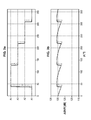
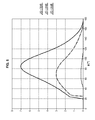
- the Figures 3a-3b and 4a-4b are simulation results providing a comparison, in the presence of a jammer, between the standard selection mode where only the antenna gain in the direction of the satellite is taken into account and the selection mode according to the invention.
- the power density of the thermal noise seen by the different channels is set at -200 dBW / Hz.
- the figures 3a and 4a illustrate which antenna is selected according to the angle of rotation of the carrier relative to the direction of the satellite.
- the figures 3b and 3c represent the pseudo signal-to-noise ratio of the selected antenna, again depending on the rotation angle of the carrier.
- the dashed lines illustrate the standard selection mode while the solid lines illustrate the selection mode according to the invention.
- the signal-to-noise pseudo-signal gain ⁇ SNIR with switching according to the invention is relatively negligible (+ 0.2 dB). But at this level, the acquisition of GPS signals P (Y) for example is widely accessible.
- the gain of ⁇ SNIR with switching according to the invention is 3 dB.
- a gain of a few decibels makes it possible to achieve the acquisition of GPS P (Y) signals with a much better probability of success, compared to a standard antenna switching strategy.
- the improvement of ⁇ SNIR is too low to justify switching to an alternative antenna. The improvement is however significant when the jammer and the satellite are in directions apart from each other, especially when the level of interference is important.
Landscapes
- Engineering & Computer Science (AREA)
- Radar, Positioning & Navigation (AREA)
- Remote Sensing (AREA)
- Computer Networks & Wireless Communication (AREA)
- Physics & Mathematics (AREA)
- General Physics & Mathematics (AREA)
- Signal Processing (AREA)
- Variable-Direction Aerials And Aerial Arrays (AREA)
- Position Fixing By Use Of Radio Waves (AREA)
Applications Claiming Priority (1)
| Application Number | Priority Date | Filing Date | Title |
|---|---|---|---|
| FR1200846A FR2988485B1 (fr) | 2012-03-21 | 2012-03-21 | Procede et recepteur pour une commutation d'antennes gnss sur un porteur tournant |
Publications (2)
| Publication Number | Publication Date |
|---|---|
| EP2642318A2 true EP2642318A2 (de) | 2013-09-25 |
| EP2642318A3 EP2642318A3 (de) | 2015-06-03 |
Family
ID=47877950
Family Applications (1)
| Application Number | Title | Priority Date | Filing Date |
|---|---|---|---|
| EP13159959.9A Withdrawn EP2642318A3 (de) | 2012-03-21 | 2013-03-19 | Verfahren und Empfänger für eine GNSS-Antennenschaltung auf einer drehbaren Halterung |
Country Status (2)
| Country | Link |
|---|---|
| EP (1) | EP2642318A3 (de) |
| FR (1) | FR2988485B1 (de) |
Cited By (2)
| Publication number | Priority date | Publication date | Assignee | Title |
|---|---|---|---|---|
| CN104407358A (zh) * | 2014-12-01 | 2015-03-11 | 长沙海格北斗信息技术有限公司 | 北斗二代卫星信号再生式信号源及生成方法 |
| CN112596078A (zh) * | 2020-12-19 | 2021-04-02 | 中国电波传播研究所(中国电子科技集团公司第二十二研究所) | 一种基于载噪比统计的卫星导航欺骗干扰检测方法 |
Citations (1)
| Publication number | Priority date | Publication date | Assignee | Title |
|---|---|---|---|---|
| EP2336800A1 (de) | 2009-12-15 | 2011-06-22 | Sagem Defense Securite | Verfahren und Empfänger zur Unterdrückung eines Störsignals |
Family Cites Families (5)
| Publication number | Priority date | Publication date | Assignee | Title |
|---|---|---|---|---|
| US6883747B2 (en) * | 2003-03-28 | 2005-04-26 | Northrop Grumman Corporation | Projectile guidance with accelerometers and a GPS receiver |
| US6825804B1 (en) * | 2003-07-09 | 2004-11-30 | Rockwell Collins, Inc. | Interference-aided navigation with cyclic jammer cancellation |
| US7414581B2 (en) * | 2006-01-06 | 2008-08-19 | Honeywell International Inc. | Method for improved signal to noise ratio estimation |
| US8159391B2 (en) * | 2008-11-13 | 2012-04-17 | Ecole Polytechnique Federale De Lausanne (Epfl) | Method to secure GNSS based locations in a device having GNSS receiver |
| US8106811B2 (en) * | 2009-05-15 | 2012-01-31 | Mayflower Communications Company, Inc. | Antijam protected GPS-based measurement of roll rate and roll angle of spinning platforms |
-
2012
- 2012-03-21 FR FR1200846A patent/FR2988485B1/fr active Active
-
2013
- 2013-03-19 EP EP13159959.9A patent/EP2642318A3/de not_active Withdrawn
Patent Citations (1)
| Publication number | Priority date | Publication date | Assignee | Title |
|---|---|---|---|---|
| EP2336800A1 (de) | 2009-12-15 | 2011-06-22 | Sagem Defense Securite | Verfahren und Empfänger zur Unterdrückung eines Störsignals |
Non-Patent Citations (4)
| Title |
|---|
| "Antenne ceinture globale pour la localisation, la télémesure et la télécommande de neutralisation sur un missile d'essai en vol", REVUE DE L'ÉLECTRICITÉ ET DE L'ÉLECTRONIQUE, March 2008 (2008-03-01) |
| GUPTA, .J.; LEE, T-H.: "Combining Multiple FRPA for AJ Functionality in GPS Receivers", PROCEEDINGS OF THE 23RD INTERNATIONAL TECHNICAL MEETING OF THE SATELLITE DIVISION OF THE INSTITUTE OF NAVIGATION (ION GNSS 2010, September 2010 (2010-09-01), pages 2500 - 2507 |
| R. CANTWELL; RICHARD VENTRESCA: "GPS Continuous Track on a Spinning Vehicle with Multiple Patch Antennas", ION GPS 1999, 14 September 1999 (1999-09-14) |
| TAKUJI EBINUMA ET AL.: "GPS Signal Tracking on Spinning Vehicles with Antenna Diversity Techniques", ION GNSS 2009, 22 September 2009 (2009-09-22) |
Cited By (2)
| Publication number | Priority date | Publication date | Assignee | Title |
|---|---|---|---|---|
| CN104407358A (zh) * | 2014-12-01 | 2015-03-11 | 长沙海格北斗信息技术有限公司 | 北斗二代卫星信号再生式信号源及生成方法 |
| CN112596078A (zh) * | 2020-12-19 | 2021-04-02 | 中国电波传播研究所(中国电子科技集团公司第二十二研究所) | 一种基于载噪比统计的卫星导航欺骗干扰检测方法 |
Also Published As
| Publication number | Publication date |
|---|---|
| FR2988485B1 (fr) | 2016-12-23 |
| EP2642318A3 (de) | 2015-06-03 |
| FR2988485A1 (fr) | 2013-09-27 |
Similar Documents
| Publication | Publication Date | Title |
|---|---|---|
| EP1836507B1 (de) | Positionierungsvorrichtung und -verfahren | |
| EP2674783B1 (de) | Satellitensignalempfänger, der zur lokalisierung dient | |
| EP2626723B1 (de) | Schätzverfahren der Eingangsrichtung von Navigationssignalen in einen Empfänger nach Reflexion durch die Wände eines über Satellit funktionierenden Positioniersystems | |
| EP1538455A1 (de) | Verfahren zur Kalibrierung einer adaptiven Gruppenantenne eines Satellitennavigationssystems | |
| EP2963438B1 (de) | Lokalisierung eines notsignalsenders | |
| EP3491408B1 (de) | Verfahren und system zur schätzung der richtung eines satelliten in der transferphase von einer ersten umlaufbahn zu einer missionsumlaufbahn | |
| EP2674779A1 (de) | Funknavigationssystem über Satellit mit versetzter Architektur | |
| CA2917066C (fr) | Procede et systeme de surveillance d'une phase de transfert d'un satellite d'une orbite initiale vers une orbite de mission | |
| WO2007082940A1 (fr) | Dispositif de contrôle de position(s) relative(s) par mesures de puissance, pour un engin spatial d'un groupe d'engins spatiaux en formation | |
| WO2021021212A1 (en) | Inter-frequency signal aiding for tracking satellite navigation signals | |
| EP2587691A1 (de) | Koordiniertes Verarbeitungsverfahren von Signalen, die von Baken ausgesendet werden | |
| EP1490987B1 (de) | Entstörverfahren für empfänger von spreizspektrum-funksignalen | |
| EP2609447A1 (de) | Raum-zeit-multiantennen- und multikorrelatorvorrichtung für die ablehnung von mehrfachwegen in navigationssystemen | |
| EP2221628B1 (de) | Verfahren zur Behebung von Mehrdeutigkeit, Verfahren zur Lokalisierung eines Empfängers durch Funknavigation, das eine Etappe zur Behebung von Mehrdeutigkeit umfasst, und Lokalisierungsempfänger | |
| FR2982035A1 (fr) | Procede de calibrage d'une antenne active | |
| EP2642318A2 (de) | Verfahren und Empfänger für eine GNSS-Antennenschaltung auf einer drehbaren Halterung | |
| FR2988483A1 (fr) | Dispositif de reception de signaux de radio-navigation multi-antennes | |
| Magiera et al. | Applicability of null-steering for spoofing mitigation in civilian GPS | |
| EP4413398A1 (de) | Verfahren zur verarbeitung eines gnss-signals zur abschwächung mindestens eines störsignals | |
| FR2971653A1 (fr) | Procede d'acquisition avec multi-correlation frequentielle amelioree | |
| FR3079308A1 (fr) | Dispositif multi-antennes pour la rejection de multi-trajets dans un systeme de navigation par satellite et procede associe | |
| van der Merwe et al. | Multi-antenna snapshot receiver | |
| FR2988484A1 (fr) | Dispositif de reception de signaux de radio-navigation a antennes multiples et asservissement de synchronisation commun | |
| CA2830604A1 (fr) | Procede et systeme de detection de signaux de diffusion emis par des sources terrestres et recus par un satellite | |
| Santi et al. | Passive multistatic SAR with GNSS transmitters and using joint bi/multi-static CLEAN technique |
Legal Events
| Date | Code | Title | Description |
|---|---|---|---|
| PUAI | Public reference made under article 153(3) epc to a published international application that has entered the european phase |
Free format text: ORIGINAL CODE: 0009012 |
|
| AK | Designated contracting states |
Kind code of ref document: A2 Designated state(s): AL AT BE BG CH CY CZ DE DK EE ES FI FR GB GR HR HU IE IS IT LI LT LU LV MC MK MT NL NO PL PT RO RS SE SI SK SM TR |
|
| AX | Request for extension of the european patent |
Extension state: BA ME |
|
| RAP1 | Party data changed (applicant data changed or rights of an application transferred) |
Owner name: SAGEM DEFENSE SECURITE |
|
| PUAL | Search report despatched |
Free format text: ORIGINAL CODE: 0009013 |
|
| AK | Designated contracting states |
Kind code of ref document: A3 Designated state(s): AL AT BE BG CH CY CZ DE DK EE ES FI FR GB GR HR HU IE IS IT LI LT LU LV MC MK MT NL NO PL PT RO RS SE SI SK SM TR |
|
| AX | Request for extension of the european patent |
Extension state: BA ME |
|
| RIC1 | Information provided on ipc code assigned before grant |
Ipc: G01S 19/36 20100101ALI20150427BHEP Ipc: G01S 19/21 20100101ALI20150427BHEP Ipc: G01S 19/35 20100101AFI20150427BHEP Ipc: G01S 19/26 20100101ALI20150427BHEP |
|
| 17P | Request for examination filed |
Effective date: 20151130 |
|
| RBV | Designated contracting states (corrected) |
Designated state(s): AL AT BE BG CH CY CZ DE DK EE ES FI FR GB GR HR HU IE IS IT LI LT LU LV MC MK MT NL NO PL PT RO RS SE SI SK SM TR |
|
| STAA | Information on the status of an ep patent application or granted ep patent |
Free format text: STATUS: THE APPLICATION HAS BEEN WITHDRAWN |
|
| 18W | Application withdrawn |
Effective date: 20160126 |