EP1538455A1 - Verfahren zur Kalibrierung einer adaptiven Gruppenantenne eines Satellitennavigationssystems - Google Patents
Verfahren zur Kalibrierung einer adaptiven Gruppenantenne eines Satellitennavigationssystems Download PDFInfo
- Publication number
- EP1538455A1 EP1538455A1 EP04024581A EP04024581A EP1538455A1 EP 1538455 A1 EP1538455 A1 EP 1538455A1 EP 04024581 A EP04024581 A EP 04024581A EP 04024581 A EP04024581 A EP 04024581A EP 1538455 A1 EP1538455 A1 EP 1538455A1
- Authority
- EP
- European Patent Office
- Prior art keywords
- satellite
- signals
- gain
- antenna array
- receivers
- Prior art date
- Legal status (The legal status is an assumption and is not a legal conclusion. Google has not performed a legal analysis and makes no representation as to the accuracy of the status listed.)
- Withdrawn
Links
- 230000003044 adaptive effect Effects 0.000 title claims abstract description 35
- 238000000034 method Methods 0.000 title claims abstract description 22
- 239000013598 vector Substances 0.000 claims description 8
- 238000001228 spectrum Methods 0.000 claims description 5
- 238000012545 processing Methods 0.000 claims description 2
- 230000008901 benefit Effects 0.000 description 4
- 238000003491 array Methods 0.000 description 3
- 230000001427 coherent effect Effects 0.000 description 2
- 230000010354 integration Effects 0.000 description 2
- 238000012360 testing method Methods 0.000 description 2
- 101100511466 Caenorhabditis elegans lon-1 gene Proteins 0.000 description 1
- 238000004891 communication Methods 0.000 description 1
- 238000012937 correction Methods 0.000 description 1
- 238000010586 diagram Methods 0.000 description 1
- 230000000694 effects Effects 0.000 description 1
- 238000011065 in-situ storage Methods 0.000 description 1
- 238000012423 maintenance Methods 0.000 description 1
- 238000005259 measurement Methods 0.000 description 1
- 238000005070 sampling Methods 0.000 description 1
- 230000007704 transition Effects 0.000 description 1
Images

Classifications
-
- G—PHYSICS
- G01—MEASURING; TESTING
- G01S—RADIO DIRECTION-FINDING; RADIO NAVIGATION; DETERMINING DISTANCE OR VELOCITY BY USE OF RADIO WAVES; LOCATING OR PRESENCE-DETECTING BY USE OF THE REFLECTION OR RERADIATION OF RADIO WAVES; ANALOGOUS ARRANGEMENTS USING OTHER WAVES
- G01S19/00—Satellite radio beacon positioning systems; Determining position, velocity or attitude using signals transmitted by such systems
- G01S19/01—Satellite radio beacon positioning systems transmitting time-stamped messages, e.g. GPS [Global Positioning System], GLONASS [Global Orbiting Navigation Satellite System] or GALILEO
- G01S19/13—Receivers
- G01S19/35—Constructional details or hardware or software details of the signal processing chain
- G01S19/36—Constructional details or hardware or software details of the signal processing chain relating to the receiver frond end
-
- G—PHYSICS
- G01—MEASURING; TESTING
- G01S—RADIO DIRECTION-FINDING; RADIO NAVIGATION; DETERMINING DISTANCE OR VELOCITY BY USE OF RADIO WAVES; LOCATING OR PRESENCE-DETECTING BY USE OF THE REFLECTION OR RERADIATION OF RADIO WAVES; ANALOGOUS ARRANGEMENTS USING OTHER WAVES
- G01S19/00—Satellite radio beacon positioning systems; Determining position, velocity or attitude using signals transmitted by such systems
- G01S19/01—Satellite radio beacon positioning systems transmitting time-stamped messages, e.g. GPS [Global Positioning System], GLONASS [Global Orbiting Navigation Satellite System] or GALILEO
- G01S19/13—Receivers
- G01S19/23—Testing, monitoring, correcting or calibrating of receiver elements
-
- H—ELECTRICITY
- H01—ELECTRIC ELEMENTS
- H01Q—ANTENNAS, i.e. RADIO AERIALS
- H01Q3/00—Arrangements for changing or varying the orientation or the shape of the directional pattern of the waves radiated from an antenna or antenna system
- H01Q3/26—Arrangements for changing or varying the orientation or the shape of the directional pattern of the waves radiated from an antenna or antenna system varying the relative phase or relative amplitude of energisation between two or more active radiating elements; varying the distribution of energy across a radiating aperture
- H01Q3/2605—Array of radiating elements provided with a feedback control over the element weights, e.g. adaptive arrays
-
- H—ELECTRICITY
- H01—ELECTRIC ELEMENTS
- H01Q—ANTENNAS, i.e. RADIO AERIALS
- H01Q3/00—Arrangements for changing or varying the orientation or the shape of the directional pattern of the waves radiated from an antenna or antenna system
- H01Q3/26—Arrangements for changing or varying the orientation or the shape of the directional pattern of the waves radiated from an antenna or antenna system varying the relative phase or relative amplitude of energisation between two or more active radiating elements; varying the distribution of energy across a radiating aperture
- H01Q3/267—Phased-array testing or checking devices
Definitions
- This invention relates to a method of calibrating an adaptive antenna array of a satellite system.
- the next generation of adaptive arrays for global positioning system are starting to be developed.
- Current analogue systems and the first generation of digital systems simply minimise the power of any interference, regardless of the satellite signals. These have a signal to noise ratio (SNR) of around -30dB and are ignored by the adaptive array.
- the adaptive array may enhance the gain towards a satellite, or it may decrease the gain.
- the next generation of adaptive arrays will be digital adaptive arrays, which use beamsteering on the satellite signals. Amongst the benefits of beamsteering are that the gain towards the satellite is increased, typically by 8dB, which improves navigation and further, that the modulation of the GPS signals by the adaptive array is reduced, also improving the navigation accuracy.
- a further advantage is that the more directive beam pattern reduces multipath from other directions, also improving navigation accuracy.
- the adaptive array In order to implement beamsteering the adaptive array needs to know the manifold, generally in the form of a look up table that records how the complex gains of each of the antenna elements change with direction.
- the manifold is obtained by measuring the antenna array in an anechoic chamber.
- This has a number of disadvantages including the fact that anechoic chamber time is expensive, the manifold of an antenna array will change depending on which platform it is fitted to, and maintenance work may invalidate the manifold and require it to be remeasured.
- Actually putting an antenna array on its platform in an anechoic chamber is often impractical, for example if the platform is an aircraft, which is rather larger than the average anechoic chamber.
- a method of calibrating an adaptive antenna array suitable for beamsteering of a satellite system comprises receiving spread spectrum satellite signals from a plurality of satellites at a plurality of receivers within the system; determining satellite direction relative to the antenna array orientation for each satellite signal; despreading the received signals to recover the satellite signals; calculating gain and phase information from the despread signals for a given satellite in a given direction; and storing, in a manifold store, the calculated gain and phase information at a predetermined address related to the direction of arrival of the satellite signal.
- the present invention provides a method of automatically obtaining the antenna gain and phase information needed to perform adaptive beamsteering for an adaptive array of a satellite navigation system. This avoids the need for calibration of the antenna array in an anechoic chamber and allows local scattering effects of the platform on which it is deployed to be automatically taken into account.
- the invention uses the satellite signals themselves as test sources with known directions in order to calibrate the antenna array.
- the unoptimised receiver data is sampled simultaneously from at least two receivers.
- a common Doppler offset and code timing is used for correlation at each of the plurality of receivers.
- the gain and phase information is derived by correlating data from a first receiver with a code for that satellite; correlating data from a second receiver using the common Doppler offset and code timing obtained for the first receiver; and repeating this second correlation step for all subsequent receivers, such that a vector of the complex correlation is constructed.
- a high elevation satellite with a strong signal is selected for processing first to derive the common Doppler offset and code timing.
- gaps in the manifold store are filled by interpolating previously derived gain and phase data.
- signals from between 6 and 12 satellites are received.
- the satellite system could be a satellite communication system which transmits a pilot tone for antenna calibration purposes, but preferably, the satellite system is a satellite navigation system.
- the advantage of this is that the method uses the satellite signals transmitted for navigation purposes for calibration, rather than needing an additional specific signal to be provided.
- the method of the present invention is applicable to any satellite system, but preferably, the satellite system is one of global positioning system (GPS) and Galileo.
- GPS global positioning system
- Galileo Galileo
- a self calibrating adaptive antenna array apparatus for a satellite system comprises a plurality of receivers for receiving spread spectrum satellite signals from a plurality of satellites within the system; a plurality of adaptive beamformers for optimising each receiver for a different satellite signal; recovering means for determining direction of arrival of each satellite signal relative to the antenna array orientation; a processor for despreading the received signals to recover the satellite signals and calculate gain and phase information from the despread signals for a given satellite in a given direction; and a manifold store for storing the calculated gain and phase information at a predetermined address related to the direction of arrival of the satellite signal.
- This invention enables an adaptive array for a satellite receiver to calibrate itself by using the satellite signals themselves.
- the satellite system is a satellite navigation system.
- an adaptive array calibrates itself, in-situ, taking account of the scattering from the platform it is fitted to.
- Fig. 1 shows an example of an adaptive array 1 which comprises at least two digital receivers (downconverters) 2 and at least two adaptive beamformers 3.
- the receivers 2 receive RF signals at their antennas and convert the RF signals to complex digital baseband within their circuits.
- Each receiver 2 provides an input to every adaptive beamformer 3 simultaneously and also to a store 4.
- Each adaptive beamformer optimises the gain towards one satellite by adapting its weighting, while cancelling any interference. Satellite signals are well below the noise level, so one cannot get direct gain and phase data.
- the beamformed signals are the best ratio of signal to interference plus noise for the respective satellite.
- each adaptive beamformer outputs from each adaptive beamformer and input to a tracking channel in a receiver 5, GPS for this example, via a digital interface and the receiver 5 recovers the satellite signals for navigational purposes in a conventional manner by despreading the received spread spectrum signal, measuring the timing and extracting advance information.
- the GPS receiver 5 is able to output the absolute direction of each satellite that it is tracking and this data is input to a beamsteering control processor 6 as azimuth and elevation data relative to true north.
- the control processor 6 combines the satellite direction information with platform attitude information, typically from an inertial navigation system (not shown), in order to compute the directions of the satellites relative to the orientation of the antenna array 1.
- Corresponding gain vectors are then looked up in a manifold store 7 and supplied to the adaptive beamformers 3, so that they can optimise the gain, i.e. beamsteer, on the satellites.
- FIG. 1 illustrates a self-calibrating beamsteering adaptive array for GPS provided with only two receivers for simplicity, but in general at least seven receivers and twelve adaptive beamformers would be provided, with corresponding connections to one another and the store.
- the number of adaptive beamformers is determined by the maximum number of satellites that the GPS set can track simultaneously, whereas the number of receivers is related to the number of satellites visible at any one time, which tends to be between 5 and 12.
- the content of the manifold store 7 is derived in a manifold calculation processor 8 using the satellite direction information relative to the platform as provided by the beamsteering control processor 6 and unrecovered baseband data direct from each digital receiver from the store 4.
- the processor 8 collects a block of the receiver data.
- the receiver data is sampled simultaneously in at least two of the receivers 2. This data is then processed in the processor 8 to recover the satellite signals.
- a common Doppler offset and code timing is used for the two or more receivers, so that the difference in amplitude and phase of the resulting correlation peaks relates just to the difference in gain of the antenna array, and receivers, for the given satellite direction.
- the inputs to the manifold calculation processor 8 are a list of the satellites that are currently visible, their azimuths and elevations relative to the platform and a block of data that was collected simultaneously from at least two downconverters 2.
- the GPS coarse acquisition (C/A) code is typically used, as this is a simple unencrypted code. Other codes could be used depending upon the satellite system and security limitations.
- the size of the data block needs to be large enough for sufficient integration gain to be available to recover the satellite signals. Typically this is around 20ms of data.
- the manifold calculation processor proceeds in a number of steps. For the first step it needs to acquire the satellite signals, just like a normal GPS receiver.
- a strong (high elevation) satellite signal is selected and then a search in time and Doppler is performed by correlating the data from one of the downconverters with the code for that satellite. This is typically performed in 1ms coherent blocks with incoherent combining of the block results to give a total integration time of 20ms. Once the initial code time and Doppler frequency have been estimated, these estimates can be refined by determining any code phase transition and calculating the coherent combination of the blocks across the 20ms.
- the next step undertaken by the manifold calculation processor 8 is to repeat the above calculations for the other satellites in the list.
- the code timing estimate from the first satellite can be used to reduce the uncertainty in the code timing for the other satellites.
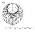
- Fig. 2 illustrates a typical sky plot showing how satellite coverage changes with time (in hours), sampling every 10 minutes, and also giving an indication of which satellites are available to use in the calibration process.
- the measurements were taken at Lat 50:58:0 N, Lon 1:34:0 W, with a threshold elevation of 5 degrees and 27 satellites were considered. It can be seen that little coverage is achieved to the North in this example. To overcome this, the platform can be rotated 180° in azimuth mid-way through the calibration.
- the manifold store is likely to store the gain information on a regular grid in azimuth and elevation.
- the processor 8 can directly fill in the manifold store with the gain vectors that coincide with grid values. For the grid values that do not directly coincide with a measured direction of arrival, interpolation of the measured values can be used to give the required gain vector.
- the gain values measured by the above process are strictly a combination of the relative antenna array gains and the relative downconverter array gains.
- the downconverters 2 include a receiver calibration process (needed for beamsteering anyway) that periodically injects a common test signal into the downconverters, measures their relative gains and then applies corrections in each downconverter to remove any mismatch.
- the adaptive beamformers can operate in a non-adaptive mode where a single antenna signal is simply passed to the output of the beamformer.
- the user can choose to perform the self-calibration at a time and place in which good signals can be obtained from the satellites i.e. away from obstructions and sources of interference. Once calibrated, the values remain valid unless the cable connections or platform on which the array is mounted change.
- a major advantage of an adaptive, i.e. beamsteering array is that it makes the satellite signals stronger e.g. by up to 8dBs. This allows reception of satellites with low signal e.g. due to trees etc, and improves the navigational performance of the system, by increasing satellite availability, which is particularly useful for landing aeroplanes. Self-calibration ensures that the most accurate values of gain are present in the manifold store, improving the effectiveness of the beamsteering.
Landscapes
- Engineering & Computer Science (AREA)
- Radar, Positioning & Navigation (AREA)
- Remote Sensing (AREA)
- Computer Networks & Wireless Communication (AREA)
- Physics & Mathematics (AREA)
- General Physics & Mathematics (AREA)
- Signal Processing (AREA)
- Position Fixing By Use Of Radio Waves (AREA)
- Variable-Direction Aerials And Aerial Arrays (AREA)
Applications Claiming Priority (2)
| Application Number | Priority Date | Filing Date | Title |
|---|---|---|---|
| GB0326906 | 2003-11-19 | ||
| GB0326906A GB2408387B (en) | 2003-11-19 | 2003-11-19 | A method of calibrating an adaptive antenna array of a satellite system |
Publications (1)
| Publication Number | Publication Date |
|---|---|
| EP1538455A1 true EP1538455A1 (de) | 2005-06-08 |
Family
ID=29764057
Family Applications (1)
| Application Number | Title | Priority Date | Filing Date |
|---|---|---|---|
| EP04024581A Withdrawn EP1538455A1 (de) | 2003-11-19 | 2004-10-15 | Verfahren zur Kalibrierung einer adaptiven Gruppenantenne eines Satellitennavigationssystems |
Country Status (3)
| Country | Link |
|---|---|
| US (1) | US7304605B2 (de) |
| EP (1) | EP1538455A1 (de) |
| GB (1) | GB2408387B (de) |
Cited By (2)
| Publication number | Priority date | Publication date | Assignee | Title |
|---|---|---|---|---|
| CN104849731A (zh) * | 2015-04-28 | 2015-08-19 | 中国电子科技集团公司第三十六研究所 | 一种天线阵元通道的校准方法、装置及接收机 |
| CN109239741A (zh) * | 2018-09-30 | 2019-01-18 | 西南电子技术研究所(中国电子科技集团公司第十研究所) | 导航卫星多阵元天线自动校准测试系统 |
Families Citing this family (36)
| Publication number | Priority date | Publication date | Assignee | Title |
|---|---|---|---|---|
| GB2418536B (en) * | 2004-09-27 | 2008-12-03 | Nortel Networks Ltd | Method of antenna calibration |
| GB2418537B (en) * | 2004-09-27 | 2008-10-08 | Nortel Networks Ltd | Antenna calibration method |
| US20060240784A1 (en) * | 2005-04-22 | 2006-10-26 | Qualcomm Incorporated | Antenna array calibration for wireless communication systems |
| US8498669B2 (en) * | 2005-06-16 | 2013-07-30 | Qualcomm Incorporated | Antenna array calibration for wireless communication systems |
| US7042393B1 (en) * | 2005-09-16 | 2006-05-09 | Northrop Grumman Corporation | Thinned array antenna system |
| US9118111B2 (en) * | 2005-11-02 | 2015-08-25 | Qualcomm Incorporated | Antenna array calibration for wireless communication systems |
| US8280430B2 (en) * | 2005-11-02 | 2012-10-02 | Qualcomm Incorporated | Antenna array calibration for multi-input multi-output wireless communication systems |
| US7786933B2 (en) * | 2007-05-21 | 2010-08-31 | Spatial Digital Systems, Inc. | Digital beam-forming apparatus and technique for a multi-beam global positioning system (GPS) receiver |
| US9435893B2 (en) | 2007-05-21 | 2016-09-06 | Spatial Digital Systems, Inc. | Digital beam-forming apparatus and technique for a multi-beam global positioning system (GPS) receiver |
| US7768453B2 (en) * | 2008-08-08 | 2010-08-03 | Raytheon Company | Dynamically correcting the calibration of a phased array antenna system in real time to compensate for changes of array temperature |
| US8130904B2 (en) | 2009-01-29 | 2012-03-06 | The Invention Science Fund I, Llc | Diagnostic delivery service |
| US8116429B2 (en) | 2009-01-29 | 2012-02-14 | The Invention Science Fund I, Llc | Diagnostic delivery service |
| US8130145B2 (en) * | 2009-06-24 | 2012-03-06 | Qualcomm Incorporated | Receive diversity in GNSS receivers |
| US8044857B2 (en) * | 2009-08-26 | 2011-10-25 | Raytheon Company | System and method for correcting global navigation satellite system pseudorange measurements in receivers having controlled reception pattern antennas |
| US8089402B2 (en) * | 2009-08-26 | 2012-01-03 | Raytheon Company | System and method for correcting global navigation satellite system carrier phase measurements in receivers having controlled reception pattern antennas |
| US8154445B2 (en) | 2010-03-30 | 2012-04-10 | Raytheon Company | System and method for frequency domain correction of global navigation satellite system pseudorance measurements in receivers having controlled reception pattern antennas |
| US8264406B2 (en) * | 2010-04-14 | 2012-09-11 | Motorola Mobility Llc | Manifold calibration for a communication system |
| US8565798B2 (en) * | 2010-07-26 | 2013-10-22 | Rincon Research Corporation | Geo-directed adaptive antenna array |
| US8676192B2 (en) * | 2011-02-09 | 2014-03-18 | Qualcomm Incorporated | High data rate aircraft to ground communication antenna system |
| US20120249366A1 (en) * | 2011-04-04 | 2012-10-04 | Raytheon Company | Communications on the move antenna system |
| US9653804B2 (en) * | 2011-06-15 | 2017-05-16 | Raytheon Company | Multi-aperture electronically scanned arrays and methods of use |
| US9319172B2 (en) | 2011-10-14 | 2016-04-19 | Qualcomm Incorporated | Interference mitigation techniques for air to ground systems |
| US9680232B2 (en) | 2012-05-07 | 2017-06-13 | Qualcomm Incorporated | Graded-ground design in a millimeter-wave radio module |
| US20140320344A1 (en) * | 2012-05-07 | 2014-10-30 | QUALCOMM ATHEROS Incorporated | Techniques for operating phased array antennas in millimeterwave radio modules |
| CA2831325A1 (en) * | 2012-12-18 | 2014-06-18 | Panasonic Avionics Corporation | Antenna system calibration |
| US10371822B2 (en) * | 2013-02-21 | 2019-08-06 | Lockheed Martin Corporation | Antenna array calibration |
| FR3047568B1 (fr) | 2016-02-05 | 2018-02-16 | Thales | Methode de calibrage d'un recepteur de radio-navigation par satellites |
| CN106908810B (zh) * | 2017-01-13 | 2019-08-09 | 北京空间飞行器总体设计部 | 一种多长码复合导航信号相位一致性标定方法 |
| US10608760B2 (en) | 2018-04-12 | 2020-03-31 | Gogo Llc | Systems and methods for detecting satellite-based communication interference |
| CN108957411A (zh) * | 2018-05-17 | 2018-12-07 | 中国人民解放军国防科技大学 | 一种高精度阵列信号生成方法 |
| GB2585221B (en) | 2019-07-03 | 2023-12-27 | Raytheon Systems Ltd | Global navigation satellite system (gnss) anti-spoofing techniques |
| GB2585222B (en) | 2019-07-03 | 2022-10-12 | Raytheon Systems Ltd | Autonomous vehicles supporting global navigation satellite system (gnss) anti-spoofing |
| GB2588182B (en) | 2019-10-11 | 2022-01-05 | Raytheon Systems Ltd | Global navigation satellite system (GNSS) anti-spoofing techniques based on similarities of gain vectors |
| US11616565B2 (en) | 2021-06-30 | 2023-03-28 | Gogo Business Aviation Llc | Beam pointing fine tuning for vehicle-based antennas |
| CN113640837B (zh) * | 2021-08-11 | 2024-01-26 | 中国科学院微小卫星创新研究院 | 导航卫星对高轨航天器服务能力提升方法 |
| US12413319B2 (en) * | 2022-08-12 | 2025-09-09 | Northrop Grumman Systems Corporation | Testing a signal path |
Citations (3)
| Publication number | Priority date | Publication date | Assignee | Title |
|---|---|---|---|---|
| US5917446A (en) * | 1995-11-08 | 1999-06-29 | The Charles Stark Draper Laboratory, Inc. | Radio-wave reception system using inertial data in the receiver beamforming operation |
| US5952968A (en) | 1997-09-15 | 1999-09-14 | Rockwell International Corporation | Method and apparatus for reducing jamming by beam forming using navigational data |
| WO2001045302A1 (en) * | 1999-12-18 | 2001-06-21 | Roke Manor Research Limited | Improvements in or relating to the reception of spread spectrum signals using adaptive antenna arrays |
Family Cites Families (8)
| Publication number | Priority date | Publication date | Assignee | Title |
|---|---|---|---|---|
| US6009335A (en) * | 1997-09-26 | 1999-12-28 | Rockwell Science Center, Inc. | Method of calibrating and testing spatial nulling antenna |
| US6421000B1 (en) * | 2000-06-08 | 2002-07-16 | Rockwell Collins, Inc. | GPS multipath mitigation using a multi-element antenna array |
| KR100617749B1 (ko) * | 2000-08-16 | 2006-08-28 | 삼성전자주식회사 | 이동통신 시스템에서 쥐피에스 신호를 이용한 기지국안테나 어레이장치 및 송수신 빔 형성 방법 |
| US6377211B1 (en) * | 2000-12-13 | 2002-04-23 | Lockheed Martin Corporation | Apparatus and method for pointing a directional device from a moving vehicle toward a spacecraft |
| US6598009B2 (en) * | 2001-02-01 | 2003-07-22 | Chun Yang | Method and device for obtaining attitude under interference by a GSP receiver equipped with an array antenna |
| US6690917B2 (en) * | 2001-11-15 | 2004-02-10 | Qualcomm Incorporated | System and method for automatic determination of azimuthal and elevation direction of directional antennas and calibration thereof |
| US7009557B2 (en) * | 2001-07-11 | 2006-03-07 | Lockheed Martin Corporation | Interference rejection GPS antenna system |
| US7088288B1 (en) * | 2003-01-10 | 2006-08-08 | Xilinx, Inc. | Method and circuit for controlling an antenna system |
-
2003
- 2003-11-19 GB GB0326906A patent/GB2408387B/en not_active Expired - Fee Related
-
2004
- 2004-10-15 EP EP04024581A patent/EP1538455A1/de not_active Withdrawn
- 2004-11-17 US US10/989,543 patent/US7304605B2/en not_active Expired - Fee Related
Patent Citations (3)
| Publication number | Priority date | Publication date | Assignee | Title |
|---|---|---|---|---|
| US5917446A (en) * | 1995-11-08 | 1999-06-29 | The Charles Stark Draper Laboratory, Inc. | Radio-wave reception system using inertial data in the receiver beamforming operation |
| US5952968A (en) | 1997-09-15 | 1999-09-14 | Rockwell International Corporation | Method and apparatus for reducing jamming by beam forming using navigational data |
| WO2001045302A1 (en) * | 1999-12-18 | 2001-06-21 | Roke Manor Research Limited | Improvements in or relating to the reception of spread spectrum signals using adaptive antenna arrays |
Non-Patent Citations (1)
| Title |
|---|
| ALONSO J I ET AL: "LOW COST ELECTRONICALLY STEERED ANTENNA AND RECEIVER SYSTEM FOR MOBILE SATELLITE COMMUNICATIONS", IEEE TRANSACTIONS ON MICROWAVE THEORY AND TECHNIQUES, IEEE INC. NEW YORK, US, vol. 44, no. 12, PART 2, December 1996 (1996-12-01), pages 2438 - 2448, XP000636426, ISSN: 0018-9480 * |
Cited By (4)
| Publication number | Priority date | Publication date | Assignee | Title |
|---|---|---|---|---|
| CN104849731A (zh) * | 2015-04-28 | 2015-08-19 | 中国电子科技集团公司第三十六研究所 | 一种天线阵元通道的校准方法、装置及接收机 |
| CN104849731B (zh) * | 2015-04-28 | 2017-07-14 | 中国电子科技集团公司第三十六研究所 | 一种天线阵元通道的校准方法、装置及接收机 |
| CN109239741A (zh) * | 2018-09-30 | 2019-01-18 | 西南电子技术研究所(中国电子科技集团公司第十研究所) | 导航卫星多阵元天线自动校准测试系统 |
| CN109239741B (zh) * | 2018-09-30 | 2023-03-28 | 西南电子技术研究所(中国电子科技集团公司第十研究所) | 导航卫星多阵元天线自动校准测试系统 |
Also Published As
| Publication number | Publication date |
|---|---|
| US20050162305A1 (en) | 2005-07-28 |
| GB2408387B (en) | 2005-10-19 |
| GB2408387A (en) | 2005-05-25 |
| US7304605B2 (en) | 2007-12-04 |
| GB0326906D0 (en) | 2003-12-24 |
Similar Documents
| Publication | Publication Date | Title |
|---|---|---|
| US7304605B2 (en) | Method of calibrating an adaptive antenna array of a satellite navigation system | |
| US6535801B1 (en) | Method and apparatus for accurately determining the position of satellites in geosynchronous orbits | |
| EP2535738B1 (de) | Verbesserte Antennenstrahlformung zur Verfolgung eines Sendersignals | |
| EP2049915B1 (de) | Benutzerempfänger für ein globales positionierungssystem (gps), verarbeitung geometrischer oberflächen zur erfassung kohärenter all-in-view-prn-codes und bestimmung einer navigationsanwendung | |
| US6922546B1 (en) | GPS signal acquisition based on frequency-domain and time-domain processing | |
| US12117539B2 (en) | Inter-frequency signal aiding for tracking satellite navigation signals | |
| CN113805208B (zh) | 一种适用于导航接收机的gnss-ir测高方法 | |
| EP1148344A1 (de) | Positionsbestimmung eines drahtlosen Terminals mit Satelliten-Positionierungssignalen oder Bassistationssignalen | |
| US11255977B2 (en) | Systems for and methods of nullsteering in a receiver | |
| US6154173A (en) | Method and apparatus for processing multipath reflection effects in timing systems | |
| JP3593960B2 (ja) | マルチビーム空中線装置 | |
| US7110474B2 (en) | Method for determining a boundary of an information element, a system, and an electronic device | |
| CN110927751A (zh) | 一种基于载波相位测量的阵列天线自适应校正实现方法 | |
| Vagle et al. | Characterization of GNSS measurement distortions due to antenna array processing in the presence of interference signals | |
| US11237274B2 (en) | Multi-antenna device for the rejection of multi-paths in a satellite navigation system and associated method | |
| JP2010521667A (ja) | 多衛星測位(ALLINVIEW)でのコヒーレントなグローバルポジショニングシステム(GPS)信号の擬似ランダムノイズ(PRN)コード捕捉およびナビゲーションソリューション(NavigationSolution)の算出のための方法およびシステム | |
| US7864898B2 (en) | Systems and methods for signal acquistion in navigational satellite signal receivers | |
| EP4439127A1 (de) | Verfahren zur korrektur eines ionosphärischen fehlers bei pseudostreckenmessungen in einem gnss-empfänger, entsprechende empfängervorrichtung und computerprogrammprodukt | |
| van der Merwe et al. | Multi-antenna snapshot receiver | |
| Yang et al. | In-Situ calibration of GPS antenna array with ambient signals | |
| Soloviev et al. | Collaborative GNSS signal processing | |
| EP2177929B1 (de) | Navigationssatellitenverfolgungsverfahren und -empfängerstation | |
| Draganov et al. | Synthetic aperture navigation in multipath environments | |
| Siebert et al. | Novel Multipath Mitigation Technique for Antenna Arrays Based on Multi-Correlator Structures | |
| CN115856943A (zh) | 一种基于三线天线的星载全视场四模gnss接收系统 |
Legal Events
| Date | Code | Title | Description |
|---|---|---|---|
| PUAI | Public reference made under article 153(3) epc to a published international application that has entered the european phase |
Free format text: ORIGINAL CODE: 0009012 |
|
| AK | Designated contracting states |
Kind code of ref document: A1 Designated state(s): AT BE BG CH CY CZ DE DK EE ES FI FR GB GR HU IE IT LI LU MC NL PL PT RO SE SI SK TR |
|
| AX | Request for extension of the european patent |
Extension state: AL HR LT LV MK |
|
| 17P | Request for examination filed |
Effective date: 20050909 |
|
| AKX | Designation fees paid |
Designated state(s): AT BE BG CH CY CZ DE DK EE ES FI FR GB GR HU IE IT LI LU MC NL PL PT RO SE SI SK TR |
|
| 17Q | First examination report despatched |
Effective date: 20090722 |
|
| STAA | Information on the status of an ep patent application or granted ep patent |
Free format text: STATUS: THE APPLICATION IS DEEMED TO BE WITHDRAWN |
|
| 18D | Application deemed to be withdrawn |
Effective date: 20120503 |