EP2642306A1 - High voltage testing device - Google Patents
High voltage testing device Download PDFInfo
- Publication number
- EP2642306A1 EP2642306A1 EP11838064.1A EP11838064A EP2642306A1 EP 2642306 A1 EP2642306 A1 EP 2642306A1 EP 11838064 A EP11838064 A EP 11838064A EP 2642306 A1 EP2642306 A1 EP 2642306A1
- Authority
- EP
- European Patent Office
- Prior art keywords
- high voltage
- coaxial cable
- capacitor
- testing device
- conductor
- Prior art date
- Legal status (The legal status is an assumption and is not a legal conclusion. Google has not performed a legal analysis and makes no representation as to the accuracy of the status listed.)
- Granted
Links
- 238000012360 testing method Methods 0.000 title claims abstract description 74
- 239000003990 capacitor Substances 0.000 claims abstract description 52
- 239000004020 conductor Substances 0.000 claims abstract description 52
- 238000009413 insulation Methods 0.000 claims abstract description 27
- 230000002159 abnormal effect Effects 0.000 claims description 4
- 239000011810 insulating material Substances 0.000 claims description 3
- 238000010586 diagram Methods 0.000 description 8
- 230000001052 transient effect Effects 0.000 description 5
- 230000008859 change Effects 0.000 description 3
- 239000012777 electrically insulating material Substances 0.000 description 3
- 230000006866 deterioration Effects 0.000 description 2
- 230000015556 catabolic process Effects 0.000 description 1
- 239000003989 dielectric material Substances 0.000 description 1
- 230000006872 improvement Effects 0.000 description 1
- 238000007689 inspection Methods 0.000 description 1
- 239000012212 insulator Substances 0.000 description 1
- 238000000034 method Methods 0.000 description 1
- 238000012986 modification Methods 0.000 description 1
- 230000004048 modification Effects 0.000 description 1
- 230000008520 organization Effects 0.000 description 1
- 239000000126 substance Substances 0.000 description 1
- 230000003245 working effect Effects 0.000 description 1
Images



Classifications
-
- G—PHYSICS
- G01—MEASURING; TESTING
- G01R—MEASURING ELECTRIC VARIABLES; MEASURING MAGNETIC VARIABLES
- G01R31/00—Arrangements for testing electric properties; Arrangements for locating electric faults; Arrangements for electrical testing characterised by what is being tested not provided for elsewhere
- G01R31/12—Testing dielectric strength or breakdown voltage ; Testing or monitoring effectiveness or level of insulation, e.g. of a cable or of an apparatus, for example using partial discharge measurements; Electrostatic testing
- G01R31/1227—Testing dielectric strength or breakdown voltage ; Testing or monitoring effectiveness or level of insulation, e.g. of a cable or of an apparatus, for example using partial discharge measurements; Electrostatic testing of components, parts or materials
- G01R31/1263—Testing dielectric strength or breakdown voltage ; Testing or monitoring effectiveness or level of insulation, e.g. of a cable or of an apparatus, for example using partial discharge measurements; Electrostatic testing of components, parts or materials of solid or fluid materials, e.g. insulation films, bulk material; of semiconductors or LV electronic components or parts; of cable, line or wire insulation
- G01R31/1272—Testing dielectric strength or breakdown voltage ; Testing or monitoring effectiveness or level of insulation, e.g. of a cable or of an apparatus, for example using partial discharge measurements; Electrostatic testing of components, parts or materials of solid or fluid materials, e.g. insulation films, bulk material; of semiconductors or LV electronic components or parts; of cable, line or wire insulation of cable, line or wire insulation, e.g. using partial discharge measurements
-
- G—PHYSICS
- G01—MEASURING; TESTING
- G01R—MEASURING ELECTRIC VARIABLES; MEASURING MAGNETIC VARIABLES
- G01R31/00—Arrangements for testing electric properties; Arrangements for locating electric faults; Arrangements for electrical testing characterised by what is being tested not provided for elsewhere
- G01R31/50—Testing of electric apparatus, lines, cables or components for short-circuits, continuity, leakage current or incorrect line connections
- G01R31/58—Testing of lines, cables or conductors
Definitions
- the present invention relates to a high voltage testing device which uses a coaxial cable as an object to be inspected and applies a high voltage between a center conductor (a core wire) and a shield conductor of the coaxial cable to carry out a test of an electric insulation state.
- a coaxial cable is ordinarily used.
- Such kind of coaxial cable is formed with a center conductor having a prescribed thickness and a shield conductor arranged in a tubular form so as to surround the periphery of the center conductor with a prescribed insulating material sandwiched between the shield conductor and the center conductor.
- a coaxial cable is also used.
- a capacitor may be sometimes inserted into a part of a center conductor of a coaxial cable.
- the user needs to carry out an electric inspection to ensure a safety or a quality of the electric wire. Specifically, the user recognizes that insulation is ensured between the center conductor and the shield conductor of the coaxial cable. Then, the user applies a DC high voltage (for instance, 1000 V) to a part between them to measure an insulation resistance or applies an alternating voltage (for instance, an amplitude is 1000 V) of a frequency (for instance, 50 Hz) the same as that of a commercial AC power to recognize that a problem does not arise in withstand voltage.
- a DC high voltage for instance, 1000 V
- an alternating voltage for instance, an amplitude is 1000 V
- a frequency for instance, 50 Hz
- patent literature 2 discloses an insulation monitor which monitors a deterioration of an electric insulator of an electric wire in a switchboard. Namely, a technique is disclosed that an eiectromagnetic wave radiated due to a partial discharge caused by the deterioration of the insulation is detected and monitored by using an antenna arranged in the switchboard.
- two electrodes of an insulation resistance tester are connected to a center conductor and a shield conductor of the coaxial cable as an object to be inspected and a prescribed voltage is applied to the electrodes so that a test may be simply carried out.
- a high voltage of about 1000 V is ordinarily applied.
- a withstand voltage of the capacitor itself built in the coaxial cable is ordinarily about 50 V at the most. Accordingly, when an operator makes an erroneous connecting operation during the test or when there is a problem in an insulation property of the coaxial cable itself, the capacitor of the coaxial cable may be possibly broken by applying an excessively high voltage.
- the present invention is devised by considering the above-described circumstances, and it is an object of the present invention to provide a high voltage testing device which can carry out a test of an entire part of a cable by a simple operation without breaking a capacitor even when a coaxial cable having a capacitor built therein is tested.
- a high voltage testing device is characterized by below-described (1) to (4).
- the high voltage testing device having the or the above-described (1), even when a capacitor is provided in the coaxial cable as the object to be inspected, the high voltage can be prevented from being applied between terminals of the capacitor. Further, the voltage for a test is applied to both the ends of the coaxial cable at the same time through the core wire short-circuiting part. Accordingly, an entire part of the coaxial cable can be tested by the test of one time without carrying out the tests individually two times. Even when the length of the coaxial cable as the object to be inspected is relatively large, the voltage applied between the terminals of the capacitor can be restrained from increasing.
- the high voltage testing device having the structure of the above-described (2) a change speed of the high voltage applied to the coaxial cable as the object to be inspected from the tester can be moderated.
- an influence of an inductor component in the coaxial cable is mitigated.
- the high voltage testing device having the structure of the above-described (3) when an abnormal high voltage is temporarily applied due to any cause, the surge removing circuit absorbs the abnormal high voltage. Accordingly, the voltage applied between the terminals of the capacitor can be restrained from increasing.
- the test can be safely carried out. Namely, an excessively high voltage can be prevented from being applied to the capacitor in the coaxial cable by a mal-operation.
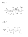
- Fig. 1 shows a specific example of a connection state when a wire harness for an antenna is tested by using a high voltage testing device of an exemplary embodiment. Further, in the present exemplary embodiment, as a representative example, a wire harness 10 for an antenna as shown in Fig. 3 is supposed to be used as an object to be inspected.
- the wire harness 10 for an antenna is used, as shown in Fig. 3 , to connect a prescribed radio unit (an input of a broadcasting radio receiver mounted on a vehicles to an antenna amplifier (an amplifier which amplifies a high frequency signal from an antenna mounted on a vehicle) Y.
- the wire harness 10 for the antenna includes a coaxial cable (1.5C2V) 11 having a length to some degree (for instance, 1.6 m) and harness side connectors 12 and 13 respectively connected to one end 11A and the other end 11 B of the coaxial cable.
- a capacitor 14 is built inside the harness side connector 12.
- the harness side connector 12 is a JASO plug adapted to a standard of Japanese Automotive Standards Organization (JASO). Further, the harness side connector 13 is a high frequency connector (HFC) for the coaxial cable.
- HFC high frequency connector
- the coaxial cable 11 has a core wire 11a which is an electrical conductor having a prescribed thickness in its central part. An outer periphery of the core wire 11 a is covered with a prescribed electrically insulating material. Further, in an outer side of the electrically insulating material, a shield conductor 11 b formed in a cylindrical configuration is arranged so as to surround the core wire 11 a. Namely, the core wire 11 a and the shield conductor 11b are coaxially arranged and the core wire and the shield conductor are insulated from each other by the electrically insulating material. Further, an outer side of the shield conductor 11 b is covered with a suitable sheath (an insulator).
- the capacitor 14. provided in the harness side connector 12 serves to match the coaxial cable with a signal source of an antenna system (for instance, in Fig. 3 , the radio unit X or the antenna amplifier Y corresponds to the antenna system) to which the coaxial cable 11 is connected, and functions as a matching correction capacitor. Namely, as shown in Fig. 3 , end of the capacitor 14 is connected to the core wire 11a in the one end 11A of the coaxial cable 11, and the other end of the capacitor 14 is connected to a central electrode 12a of the harness side connector 12. As in this structure, the wire harness 10 for the antenna has a function for matching the coaxial cable with the signal source of the antenna system.
- an electrode 12b of an outer periphery of the harness side connector 12 is connected to the shield conductor 11 b in the one end 11A of the coaxial cable 11.
- a central electrode 13a of the harness side connector 13 is connected to the core wire 11 a in the other end 11 B of the coaxial cable 11.
- An electrode 13b of an outer periphery is connected to the shield conductor 11b in the other end 11 B of the coaxial cable 11.
- the wire harness 10 for the antenna shown in Fig. 3 is tested as an object to be inspected, the wire harness for the antenna is connected to a jig for a high voltage test (a high voltage testing device) 20 as shown in Fig. 1 .
- the wire harness 10 for the antenna is bent in the form of U to mechanically and electrically connect the harness side connector (a plug) 12 of one end side thereof to a tester side connector (a jack) and, to mechanically and electrically connect the harness side connector (a female) 13 of the other end side to a tester side connector (a male) 22.
- the jig for the high voltage test 20 shown in Fig. 1 includes the tester side connectors 21 and 22 and a jig circuit 23.
- the tester side connector 21 and the tester side connector 22 are arranged at positions close to each other. Further, a central electrode 21a of the tester side connector 21 is connected to a central electrode 22a of the tester side connector 22 at a core wire short-circuiting part P1.
- An outer periphery side electrode 21 b of the tester side connector 21 is connected to an outer periphery side electrode 22b of the tester side connector 22 at a shield wire short-circuiting part P2.
- the core wire short-circuiting part P1 is connected to a terminal 24 through the jig circuit 23.
- the shield wire short-circuiting part P2 is connected to a terminal 25 through the jig circuit 23.
- the terminals 24 and 25 of the jig circuit 23 are respectively connected to output electrodes 31 and 32 of an insulation resistance/withstand voltage tester 30.
- the insulation resistance/withstand voltage tester 30 has a function for carrying out an insulation resistance test using a DC high voltage and a withstand voltage test using an AC high voltage. Namely, under a state that the DC high voltage (for instance, 1000 V) is applied between the output electrodes 31 and 32, the insulation resistance of the object to be inspected can be measured. Further, under a state that a high voltage (for instance, 1000 V) of a low frequency alternating current (for instance, 50 Hz) is applied between the output electrodes 31 and 32, whether or not an electric breakdown is generated in the object to be inspected can be identified.
- a high voltage for instance, 1000 V
- a low frequency alternating current for instance, 50 Hz
- Fig. 2 is an equivalent circuit of main parts of the electric circuit shown in Fig. 1 .
- the jig circuit 23 of the jig for the high voltage test 20 includes, as shown in Fig. 2 , a time constant circuit 23a and a surge removing circuit 23b.
- the time constant circuit 23a is provided to moderate a leading edge and a trailing edge of a wave form when an on/off of the DC voltage outputted by the insulation resistance/withstand voltage tester 30 are switched.
- the time constant circuit 23a may be formed only by one resistor and one capacitor.
- the surge removing circuit 23b is provided to protect an entire part of a system. Namely, the surge removing circuit 23b removes a surge voltage so that parts of the circuit are not respectively destroyed when an abnormally high voltage (the surge voltage) is temporarily applied due to any cause.
- the surge removing circuit 23b is formed with two diodes connected in series with polarities in reversed direction to each other. Since the surge removing circuit 23b is prepared for protection for the worst, the surge removing circuit may be omitted.
- Fig. 4 shows supposed connection states of main circuit elements of the parts which give an influence to the wire harness 10 for the antenna when a voltage for a test is applied to the wire harness 10 for the antenna shown in Fig. 1 and Fig. 3 . Substances of the circuit elements shown in Fig. 4 are respectively described blow.
- the central electrode 21a of the tester side connector 21 and the central electrode 22a of the tester side connector 22 are short-circuited at the core wire short-circuiting part P1, so that the one end and the other end of the capacitor 14 are electrically connected to each other. Accordingly, in a steady state, a voltage between both the ends of the capacitor 14 is 0 V. However, even when the DC voltage is applied from the output of the insulation resistance/withstand voltage tester 30 is applied at the time of the test, a rise and a fall of the high voltage are generated during a switch of on/off. Thus, there is a possibility that influences of the components C1, C2 and L respectively shown in Fig. 2 may appear in an AC component at that time and the high voltage may appear between both the ends of the capacitor 14. Particularly, when a length of the coaxial cable 11 is large, there is a possibility that the influences of the components C1, C2 and L may be respectively increased.
- the voltage expressed by the above-described equation (1) is temporarily applied to the capacitor 14.
- a level of the voltage exceeds a withstand voltage (for instance, 50 V) of the capacitor 14, the capacitor 14 may be possibly broken down.
- Fig. 7 shows a wave form of the voltage when the time constant circuit 23a is not provided in the jig for the high voltage test 20.
- Vin a voltage between a A and a point D
- the voltage Vc1 appears at both the ends of the capacitor 14 (C1)during a period T1 of a transient state.
- the voltage Vc1 when a change of 5 V is applied as the input voltage Vin, the voltage Vc1 of an amplitude of 3.8 V at the maximum is observed.
- the high voltage of 760 V is applied to both the ends of the capacitor 14 (C1) to electrically break down the capacitor 14.
- Fig. 8 shows a wave form of the voltage when the time constant circuit 23a is provided in the jig for the high voltage test 20.
- Vin the voltage between the point A and the point D
- the input voltage Vin the voltage between the point A and the point D
- the wire harness 10 for the antenna has a wave form the rise and fall of which are gentle like the wave form shown in Fig. 8 due to an influence of the time constant circuit 23a.
- the voltage Vc1 appearing at both the ends of the capacitor 14 (C1) is lowered to a level as low as noise.
- Fig. 9 an example of a waveform of a voltage is shown which appears between terminals of the capacitor 14 (C1) in the wire harness 10 for the antenna in an actual test state.
- the voltage Vc1 is shown which appears at both the ends of the capacitor 14 (C1) in a transient state when DC 500 V is applied as the input voltage Vin.
- a maximum value of amplitude of the voltage Vc1 is 4.68 V.
- the time constant circuit 23a is mounted on the jig for the high voltage test 20
- the high voltage exceeding the withstand voltage can be prevented from being applied between the terminals of the capacitor 14 in the transient state.
- a change of the voltage outputted from the insulation resistance/withstand voltage tester 30 is gentle, or when the influence of the inductor component L is low as in the case of the coaxial cable 11 having a relatively small length, there is a possibility that even when the time contact circuit 23a is not provided, a problem does not arise.
- Fig. 10 shows a connection state when a wire harness 40 for an antenna is tested by using a high voltage testing device of a modified example.
- the wire harness 40 for the antenna used as an object to be inspected includes two coaxial cables 41 and 43 and harness side connectors 42, 44 and 45. Namely, one end of the coaxial cable 41 and one end of the coaxial cable 43 are connected to the common harness side connector 45. The other end of the coaxial cable 41 is connected to the harness side connector 42 and the other end of the coaxial cable 43 is connected to the harness side connector 44.
- the harness side connector 42 is a JASO plug.
- the harness side connector 45 is a high frequency connector (HFC).
- the harness side connector 44 is a JASO mini-plug.
- a capacitor 46 is built in the harness side connector 42.
- a jig for a high voltage test (a high voltage testing device) 20B shown in Fig 10 is formed so that an entire part of the wire harness 40 for the antenna may be inspected only by a test of one time.
- the jig for the high voltage test 20B has tester side connectors 51, 52 and 53. Further, the tester side connector 51, the tester side connector 52 and the tester side connector 53 are arranged at mutually close positions. As shown in Fig. 10 , the tester side connector 51 is connected to the harness side connector 42. The tester side connector 52 is connected to the harness side connector 44. The tester side connector 53 is connected to the harness side connector 45.
- a central electrode of the tester side connector 51, a central electrode of the tester side connector 52 and a central electrode of the tester side connector 53 are electrically and commonly connected.
- a shield wire short-circuiting part P4 an outer periphery side electrode of the tester side connector 51, an outer periphery side electrode of the tester side connector 52 and an outer periphery side electrode of the tester side connector 53 are electrically and commonly connected.
- the high voltage testing device of the present invention can be used when an insulation resistance test or a withstand voltage test of, for instance, an antenna cable mounted on a vehicle is carried out. Especially, even when the cable as an object to be inspected has the capacitor built therein, the entire part of the cable can be completely tested only by the operation of one time, which contributes to an improvement of a working property. Further, since the test can be started only by connecting the connectors, an excessively high voltage can be prevented from being applied to the capacitor by a wrong connecting operation. Further, since the time constant circuit is mounted, an excessively high voltage can be prevented from being applied to the capacitor in a temporary transient state.
- the entire part of the cable can be tested by a simple operation without breaking down the capacitor.
Landscapes
- Physics & Mathematics (AREA)
- General Physics & Mathematics (AREA)
- Testing Electric Properties And Detecting Electric Faults (AREA)
- Testing Relating To Insulation (AREA)
Abstract
Description
- The present invention relates to a high voltage testing device which uses a coaxial cable as an object to be inspected and applies a high voltage between a center conductor (a core wire) and a shield conductor of the coaxial cable to carry out a test of an electric insulation state.
- For instance, when an input of a radio device such as a radio or a television is connected to an antenna, a coaxial cable is ordinarily used. Such kind of coaxial cable is formed with a center conductor having a prescribed thickness and a shield conductor arranged in a tubular form so as to surround the periphery of the center conductor with a prescribed insulating material sandwiched between the shield conductor and the center conductor. When an input of a broadcasting radio receiver mounted on a vehicle is connected to an antenna, such a coaxial cable is also used.
- As disclosed in patent literature 1, a capacitor may be sometimes inserted into a part of a center conductor of a coaxial cable.
- On the other hand, when a user employs an electric wire such as this kind of coaxial cable for various uses, the user needs to carry out an electric inspection to ensure a safety or a quality of the electric wire. Specifically, the user recognizes that insulation is ensured between the center conductor and the shield conductor of the coaxial cable. Then, the user applies a DC high voltage (for instance, 1000 V) to a part between them to measure an insulation resistance or applies an alternating voltage (for instance, an amplitude is 1000 V) of a frequency (for instance, 50 Hz) the same as that of a commercial AC power to recognize that a problem does not arise in withstand voltage.
- Further, for instance, patent literature 2 discloses an insulation monitor which monitors a deterioration of an electric insulator of an electric wire in a switchboard. Namely, a technique is disclosed that an eiectromagnetic wave radiated due to a partial discharge caused by the deterioration of the insulation is detected and monitored by using an antenna arranged in the switchboard.
-
- Patent Literature 1:
JP-A-2001-202836 - Patent Literature 2:
JP-A-2005-265684 - For instance, when an insulation resistance of an ordinary coaxial cable is measured, two electrodes of an insulation resistance tester are connected to a center conductor and a shield conductor of the coaxial cable as an object to be inspected and a prescribed voltage is applied to the electrodes so that a test may be simply carried out.
- However, as described above, when the coaxial cable having the capacitor inserted into a part of the center conductor is tested, various problems may possibly arise. Namely, since one end and the other end of the coaxial cable in the longitudinal direction thereof cable are separated from each other in a direct current by the capacitor, when the two electrodes of the insulation resistance tester are merely connected to the center conductor and the shield conductor in the one end of the coaxial cable, only a range from the one end of the coaxial cable to one end of the capacitor can be tested. Accordingly, after the test of the one end side of the coaxial cable is finished, the two electrodes of the insulation resistance tester are reconnected to the center conductor and the shield conductor in the other end of the same coaxial cable to carry out a test again.
- Further, when an insulation resistance test or a withstand voltage test is carried out, a high voltage of about 1000 V is ordinarily applied. A withstand voltage of the capacitor itself built in the coaxial cable is ordinarily about 50 V at the most. Accordingly, when an operator makes an erroneous connecting operation during the test or when there is a problem in an insulation property of the coaxial cable itself, the capacitor of the coaxial cable may be possibly broken by applying an excessively high voltage.
- The present invention is devised by considering the above-described circumstances, and it is an object of the present invention to provide a high voltage testing device which can carry out a test of an entire part of a cable by a simple operation without breaking a capacitor even when a coaxial cable having a capacitor built therein is tested.
- In order to achieve the above-described object, a high voltage testing device according to the present invention is characterized by below-described (1) to (4).
- (1) In a high voltage testing device which uses as an object to be inspected a coaxial cable including a central conductor and a shield conductor arranged so as to surround a periphery of the central conductor with a prescribed insulating material sandwiched between the central conductor and the shield conductor and applies a high voltage between the central conductor and the shield conductor of the coaxial cable to carry out a test of an electric insulation state, the high voltage testing device includes: a cable connecting part that respectively connects two electrodes of an output of a tester which outputs a high voltage to the central conductor and the shield conductor of the coaxial cable as the object to be inspected, and the cable connecting part includes a core wire short-circuiting part which electrically short-circuits between one end and the other end in the longitudinal direction of the central conductor of the coaxial cable and a shield wire shirt-circuiting part which electrically short-circuits between one end and the other end in the longitudinal direction of the shield conductor of the coaxial cable.
- (2) A high voltage testing device according to the above-described (1) further includes a time constant circuit that is connected between the output of the tester and an input of the cable connecting part and that has at least one resistor and at least one capacitor.
- (3) In a high voltage testing device according to the above- described (2), the time constant circuit has a surge removing circuit which absorbs an abnormal high voltage.
- (4) In a high voltage testing device according to the above-described (1), the cable connecting part includes two or more coaxial connectors which are respectively connected to two connectors provided in one end side and the other end side in the longitudinal direction of the coaxial cable as the object to be inspected.
- According to the high voltage testing device having the or the above-described (1), even when a capacitor is provided in the coaxial cable as the object to be inspected, the high voltage can be prevented from being applied between terminals of the capacitor. Further, the voltage for a test is applied to both the ends of the coaxial cable at the same time through the core wire short-circuiting part. Accordingly, an entire part of the coaxial cable can be tested by the test of one time without carrying out the tests individually two times. Even when the length of the coaxial cable as the object to be inspected is relatively large, the voltage applied between the terminals of the capacitor can be restrained from increasing.
According to the high voltage testing device having the structure of the above-described (2), a change speed of the high voltage applied to the coaxial cable as the object to be inspected from the tester can be moderated. Thus, an influence of an inductor component in the coaxial cable is mitigated. Accordingly, even when the length of the coaxial cable as the object to be inspected is relatively large, the voltage applied between the terminals of the capacitor can be restrained from increasing.
According to the high voltage testing device having the structure of the above-described (3), when an abnormal high voltage is temporarily applied due to any cause, the surge removing circuit absorbs the abnormal high voltage. Accordingly, the voltage applied between the terminals of the capacitor can be restrained from increasing.
According to the high voltage testing device having the structure of the above-described (4), when both the ends of the coaxial cable as the object to be inspected are merely connected to the two coaxial connectors of the cable connecting part, the test can be safely carried out. Namely, an excessively high voltage can be prevented from being applied to the capacitor in the coaxial cable by a mal-operation. - The present invention is briefly explained as described above. Further, when mode for carrying out the invention described below is read by referring to the attached drawings, a detail of the present invention will be more clarified.
-
- [
Fig. 1] Fig. 1 is a connection diagram showing a connection state when a wire harness for an antenna is tested by using a high voltage testing device of an exemplary embodiment. - [
Fig. 2] Fig. 2 is an electric circuit diagram showing an equivalent circuit of an electric circuit shown inFig. 1 . - [
Fig. 3] Fig. 3 is a front view of a structural example of the wire harness for the antenna as an object to be inspected. - [
Fig. 4] Fig. 4 is a schematic view showing the connection states of circuit elements of parts which respectively give an influence when a voltage for a test is applied to the wire harness for the antenna as shown inFig. 1 andFig. 3 . - [
Fig. 5] Fig. 5 is an electric circuit diagram showing an equivalent circuit of the wire harness for the antenna immediately after a Voltage for the test is applied. - [
Fig. 6] Fig. 6 is an electric circuit diagram showing the equivalent circuit of the wire harness for the antenna after the DC for the test is applied, and then, a sufficient time elapses. - [
Fig. 7] Fig. 7 is a wave form diagram showing a wave form of a voltage when a jig for a high voltage test has no time constant circuit. - [
Fig. 8] Fig. 8 is a wave form diagram showing a wave form of a voltage when the jig for the high voltage test has the time constant circuit. - [
Fig. 9] Fig. 9 is a wave form diagram showing an example of a wave form of a voltage appearing between terminals of a capacitor in the wire harness for the antenna in an actual test state. - [
Fig. 10] Fig. 10 is a connection diagram showing a connection state when the wire harness for the antenna is tested by using a high voltage testing device of a modified example. - Now, a specific exemplary embodiment of a high voltage testing device of the present invention will be described below by referring to the drawings.
-
Fig. 1 shows a specific example of a connection state when a wire harness for an antenna is tested by using a high voltage testing device of an exemplary embodiment. Further, in the present exemplary embodiment, as a representative example, awire harness 10 for an antenna as shown inFig. 3 is supposed to be used as an object to be inspected. - The
wire harness 10 for an antenna is used, as shown inFig. 3 , to connect a prescribed radio unit (an input of a broadcasting radio receiver mounted on a vehicles to an antenna amplifier (an amplifier which amplifies a high frequency signal from an antenna mounted on a vehicle) Y. Further, as shown inFig. 3 , thewire harness 10 for the antenna includes a coaxial cable (1.5C2V) 11 having a length to some degree (for instance, 1.6 m) andharness side connectors end 11A and theother end 11 B of the coaxial cable. Further, inside theharness side connector 12, acapacitor 14 is built. - Specifically, the
harness side connector 12 is a JASO plug adapted to a standard of Japanese Automotive Standards Organization (JASO). Further, theharness side connector 13 is a high frequency connector (HFC) for the coaxial cable. - The
coaxial cable 11 has acore wire 11a which is an electrical conductor having a prescribed thickness in its central part. An outer periphery of thecore wire 11 a is covered with a prescribed electrically insulating material. Further, in an outer side of the electrically insulating material, ashield conductor 11 b formed in a cylindrical configuration is arranged so as to surround thecore wire 11 a. Namely, thecore wire 11 a and theshield conductor 11b are coaxially arranged and the core wire and the shield conductor are insulated from each other by the electrically insulating material. Further, an outer side of theshield conductor 11 b is covered with a suitable sheath (an insulator). - The
capacitor 14. provided in theharness side connector 12 serves to match the coaxial cable with a signal source of an antenna system (for instance, inFig. 3 , the radio unit X or the antenna amplifier Y corresponds to the antenna system) to which thecoaxial cable 11 is connected, and functions as a matching correction capacitor. Namely, as shown inFig. 3 , end of thecapacitor 14 is connected to thecore wire 11a in the oneend 11A of thecoaxial cable 11, and the other end of thecapacitor 14 is connected to acentral electrode 12a of theharness side connector 12. As in this structure, thewire harness 10 for the antenna has a function for matching the coaxial cable with the signal source of the antenna system. - Further, an
electrode 12b of an outer periphery of theharness side connector 12 is connected to theshield conductor 11 b in the oneend 11A of thecoaxial cable 11. Acentral electrode 13a of theharness side connector 13 is connected to thecore wire 11 a in theother end 11 B of thecoaxial cable 11. Anelectrode 13b of an outer periphery is connected to theshield conductor 11b in theother end 11 B of thecoaxial cable 11. - When the
wire harness 10 for the antenna shown inFig. 3 is tested as an object to be inspected, the wire harness for the antenna is connected to a jig for a high voltage test (a high voltage testing device) 20 as shown inFig. 1 . Namely, since thecoaxial cable 11 has a flexibility, thewire harness 10 for the antenna is bent in the form of U to mechanically and electrically connect the harness side connector (a plug) 12 of one end side thereof to a tester side connector (a jack) and, to mechanically and electrically connect the harness side connector (a female) 13 of the other end side to a tester side connector (a male) 22. - The jig for the
high voltage test 20 shown inFig. 1 includes thetester side connectors jig circuit 23. Thetester side connector 21 and thetester side connector 22 are arranged at positions close to each other. Further, acentral electrode 21a of thetester side connector 21 is connected to acentral electrode 22a of thetester side connector 22 at a core wire short-circuiting part P1. An outerperiphery side electrode 21 b of thetester side connector 21 is connected to an outerperiphery side electrode 22b of thetester side connector 22 at a shield wire short-circuiting part P2. - The core wire short-circuiting part P1 is connected to a terminal 24 through the
jig circuit 23. The shield wire short-circuiting part P2 is connected to a terminal 25 through thejig circuit 23. Theterminals jig circuit 23 are respectively connected tooutput electrodes voltage tester 30. - The insulation resistance/withstand
voltage tester 30 has a function for carrying out an insulation resistance test using a DC high voltage and a withstand voltage test using an AC high voltage. Namely, under a state that the DC high voltage (for instance, 1000 V) is applied between theoutput electrodes output electrodes -
Fig. 2 is an equivalent circuit of main parts of the electric circuit shown inFig. 1 . Thejig circuit 23 of the jig for thehigh voltage test 20 includes, as shown inFig. 2 , a timeconstant circuit 23a and asurge removing circuit 23b. - The time
constant circuit 23a is provided to moderate a leading edge and a trailing edge of a wave form when an on/off of the DC voltage outputted by the insulation resistance/withstandvoltage tester 30 are switched. In a structural example shown inFig. 2 , two resistors and three capacitors are provided, however, the timeconstant circuit 23a may be formed only by one resistor and one capacitor. - The
surge removing circuit 23b is provided to protect an entire part of a system. Namely, thesurge removing circuit 23b removes a surge voltage so that parts of the circuit are not respectively destroyed when an abnormally high voltage (the surge voltage) is temporarily applied due to any cause. In this structural example, thesurge removing circuit 23b is formed with two diodes connected in series with polarities in reversed direction to each other. Since thesurge removing circuit 23b is prepared for protection for the worst, the surge removing circuit may be omitted. -
Fig. 4 shows supposed connection states of main circuit elements of the parts which give an influence to thewire harness 10 for the antenna when a voltage for a test is applied to thewire harness 10 for the antenna shown inFig. 1 andFig. 3 . Substances of the circuit elements shown inFig. 4 are respectively described blow. - C1: an electrostatic capacity corresponding to the
capacitor 14 in theharness side connector 12 - R: the insulation resistance between the
core wire 11 a and theshield conductor 11b - C2: a floating capacity between the
core wire 11 a and theshield conductor 11 b L: an inductor component existing in thecore wire 11 a - As shown in
Fig. 1 , thecentral electrode 21a of thetester side connector 21 and thecentral electrode 22a of thetester side connector 22 are short-circuited at the core wire short-circuiting part P1, so that the one end and the other end of thecapacitor 14 are electrically connected to each other. Accordingly, in a steady state, a voltage between both the ends of thecapacitor 14 is 0 V. However, even when the DC voltage is applied from the output of the insulation resistance/withstandvoltage tester 30 is applied at the time of the test, a rise and a fall of the high voltage are generated during a switch of on/off. Thus, there is a possibility that influences of the components C1, C2 and L respectively shown inFig. 2 may appear in an AC component at that time and the high voltage may appear between both the ends of thecapacitor 14. Particularly, when a length of thecoaxial cable 11 is large, there is a possibility that the influences of the components C1, C2 and L may be respectively increased. - The equivalent circuit of the
wire harness 10 for the antenna immediately after the DC voltage for the test is applied is represented as shown inFig. 5 . Namely, immediately after the DC voltage is applied, a counter electromotive force is generated for a short period (for instance, 8ns) by the inductor component L. Thus, a voltage Vc1 expressed by a below-described equation appears at both the ends of thecapacitor 14 due to this influence.
- Further, the equivalent circuit of the
wire harness 10 for the antenna after the DC voltage for the test is applied, and then, a sufficient time elapses is represented as shown inFig. 6 . Namely, when the sufficient time elapses after the DC voltage is applied, since the influence of the counter electromotive force of the inductor component L is eliminated, both the ends of the capacitor (C1) are short-circuited at the core wire short-circuiting part P1. Thus, both the ends of the capacitor 14 (C1) have the same electric potential. - Namely, even when one end and the other end of the
wire harness 10 for the antenna are short-circuited at the core wire short-circuiting part P1 by using the jig for thehigh voltage test 20, the voltage expressed by the above-described equation (1) is temporarily applied to thecapacitor 14. When a level of the voltage exceeds a withstand voltage (for instance, 50 V) of thecapacitor 14, thecapacitor 14 may be possibly broken down. -
Fig. 7 shows a wave form of the voltage when the timeconstant circuit 23a is not provided in the jig for thehigh voltage test 20. Namely, when an input voltage Vin (a voltage between a A and a point D) applied to thewire harness 10 for the antenna suddenly changes like the wave form shown inFig. 7 , the voltage Vc1 appears at both the ends of the capacitor 14 (C1)during a period T1 of a transient state. In an example shown inFig. 7 , when a change of 5 V is applied as the input voltage Vin, the voltage Vc1 of an amplitude of 3.8 V at the maximum is observed. Accordingly, if 1000 V is applied as the input voltage Vin, the high voltage of 760 V is applied to both the ends of the capacitor 14 (C1) to electrically break down thecapacitor 14. - On the other hand,
Fig. 8 shows a wave form of the voltage when the timeconstant circuit 23a is provided in the jig for thehigh voltage test 20. Namely, the input voltage Vin (the voltage between the point A and the point D) applied to thewire harness 10 for the antenna has a wave form the rise and fall of which are gentle like the wave form shown inFig. 8 due to an influence of the timeconstant circuit 23a.
As a result, even during a period of a transient state, the voltage Vc1 appearing at both the ends of the capacitor 14 (C1) is lowered to a level as low as noise. - In
Fig. 9 , an example of a waveform of a voltage is shown which appears between terminals of the capacitor 14 (C1) in thewire harness 10 for the antenna in an actual test state. In the example shown inFig. 9 , the voltage Vc1 is shown which appears at both the ends of the capacitor 14 (C1) in a transient state when DC 500 V is applied as the input voltage Vin. In this example, a maximum value of amplitude of the voltage Vc1 is 4.68 V. Thus, when the ordinary withstand voltage (for instance 50 V) of thecapacitor 14 is considered, a problem does not arise. - Specifically, at the time of the insulation resistance test of the
wire harness 10 for the antenna, even when the High voltage (for instance, 1000 V) outputted by the insulation resistance/withstandvoltage tester 30 is abruptly switched on and off, if the timeconstant circuit 23a is mounted on the jig for thehigh voltage test 20, the high voltage exceeding the withstand voltage can be prevented from being applied between the terminals of thecapacitor 14 in the transient state. When a change of the voltage outputted from the insulation resistance/withstandvoltage tester 30 is gentle, or when the influence of the inductor component L is low as in the case of thecoaxial cable 11 having a relatively small length, there is a possibility that even when thetime contact circuit 23a is not provided, a problem does not arise. -
Fig. 10 shows a connection state when awire harness 40 for an antenna is tested by using a high voltage testing device of a modified example. In an example shown inFig. 10 , thewire harness 40 for the antenna used as an object to be inspected includes twocoaxial cables harness side connectors coaxial cable 41 and one end of thecoaxial cable 43 are connected to the commonharness side connector 45. The other end of thecoaxial cable 41 is connected to theharness side connector 42 and the other end of thecoaxial cable 43 is connected to theharness side connector 44. - The
harness side connector 42 is a JASO plug. Theharness side connector 45 is a high frequency connector (HFC). Theharness side connector 44 is a JASO mini-plug. In theharness side connector 42, acapacitor 46 is built. - A jig for a high voltage test (a high voltage testing device) 20B shown in
Fig 10 is formed so that an entire part of thewire harness 40 for the antenna may be inspected only by a test of one time. Namely, the jig for thehigh voltage test 20B hastester side connectors tester side connector 51, thetester side connector 52 and thetester side connector 53 are arranged at mutually close positions. As shown inFig. 10 , thetester side connector 51 is connected to theharness side connector 42. Thetester side connector 52 is connected to theharness side connector 44. Thetester side connector 53 is connected to theharness side connector 45. - Further, at a core wire short-circuiting part P3, a central electrode of the
tester side connector 51, a central electrode of thetester side connector 52 and a central electrode of thetester side connector 53 are electrically and commonly connected. Further, at a shield wire short-circuiting part P4, an outer periphery side electrode of thetester side connector 51, an outer periphery side electrode of thetester side connector 52 and an outer periphery side electrode of thetester side connector 53 are electrically and commonly connected. - Accordingly, under a connected state as shown in
Fig. 10 , when a voltage is outputted from an output of an insulation resistance/withstandvoltage tester 30, the voltage can be applied to an entire part of thecoaxial cable 41 and an entire part of thecoaxial cable 43. Thus, a test of the whole part of thewire harness 40 for the antenna can be completed only by an operation of a time. - As described above, the high voltage testing device of the present invention can be used when an insulation resistance test or a withstand voltage test of, for instance, an antenna cable mounted on a vehicle is carried out. Especially, even when the cable as an object to be inspected has the capacitor built therein, the entire part of the cable can be completely tested only by the operation of one time, which contributes to an improvement of a working property. Further, since the test can be started only by connecting the connectors, an excessively high voltage can be prevented from being applied to the capacitor by a wrong connecting operation. Further, since the time constant circuit is mounted, an excessively high voltage can be prevented from being applied to the capacitor in a temporary transient state.
- The present invention is described in detail by referring to the specific exemplary embodiment, however, it is to be understood to a person with ordinary skill in the art that various changes or modifications may be added without deviating from the spirit and scope of the present invention.
- This application is based on Japanese Patent Application (Japanese Patent Application No.
2010-246474 - According to the present invention, even when the coaxial cable in which the capacitor is built is tested, the entire part of the cable can be tested by a simple operation without breaking down the capacitor.
-
- 10....wire harness for antenna
- 11... coaxial cable
- 11a....core wire
- 11b... shield conductor
- 12, 13....harness side connector
- 14....capacitor
- 20, 20B...jig for high voltage test (high voltage testing device)
- 21, 22... tester side connector
- 23...jig circuit
- 23a...time constant circuit
- 23b... surge removing circuit
- 24, 25...terminal
- 30... insulation resistance/withstand voltage tester
- 31, 32... output electrode
- 40...wire harness for antenna
- 41,43 ... coaxial cable
- 42, 44, 45... harness connector
- 46...capacitor
- 51, 52. 53... tester side connector
- P1, P3...core wire short-circuiting part
- P2, P4...shield wire short-circuiting part
- X...radio unit
- Y...antenna amplifier
Claims (4)
- A high voltage testing device which uses as an object to be inspected a coaxial cable including a central conductor and a shield conductor arranged so as to surround a periphery of the central conductor with a prescribed insulating material sandwiched between the central conductor and the shield conductor and applies a high voltage between the central conductor and the shield conductor of the coaxial cable to carry out a test of an electric insulation state, the high voltage testing device comprising:a cable connecting part that respectively connects two electrodes of an output of a tester which outputs a high voltage to the central and the shield conductor of the coaxial cable as the object to be inspected,wherein the cable connecting part includes a core wire short-circuiting part which electrically short-circuits between one end and the other end in the longitudinal direction of the central conductor of the coaxial cable and a shield wire shirt-circuiting part which electrically short-circuits between one end and the other end in the longitudinal direction of the shield conductor of the coaxial cable.
- The high voltage testing device according to claim 1, further comprising:a time constant circuit that is connected between the output of the tester and an input of the cable connecting part and that has at least one resistor and at least one capacitor.
- The high voltage testing device according to claim 2, wherein the time constant circuit has a surge removing circuit which absorbs an abnormal high voltage.
- The high voltage testing device according to claim 1, wherein the cable connecting part includes two or more coaxial connectors which are respectively connected to two connectors provided in one end side and the other end side in the longitudinal direction of the coaxial cable as the object to be inspected.
Applications Claiming Priority (2)
| Application Number | Priority Date | Filing Date | Title |
|---|---|---|---|
| JP2010246474A JP5795470B2 (en) | 2010-11-02 | 2010-11-02 | High voltage test equipment |
| PCT/JP2011/075303 WO2012060414A1 (en) | 2010-11-02 | 2011-11-02 | High voltage testing device |
Publications (3)
| Publication Number | Publication Date |
|---|---|
| EP2642306A1 true EP2642306A1 (en) | 2013-09-25 |
| EP2642306A4 EP2642306A4 (en) | 2018-04-11 |
| EP2642306B1 EP2642306B1 (en) | 2019-05-22 |
Family
ID=46024527
Family Applications (1)
| Application Number | Title | Priority Date | Filing Date |
|---|---|---|---|
| EP11838064.1A Active EP2642306B1 (en) | 2010-11-02 | 2011-11-02 | High voltage testing device |
Country Status (5)
| Country | Link |
|---|---|
| US (1) | US20130241571A1 (en) |
| EP (1) | EP2642306B1 (en) |
| JP (1) | JP5795470B2 (en) |
| CN (1) | CN103201643B (en) |
| WO (1) | WO2012060414A1 (en) |
Cited By (1)
| Publication number | Priority date | Publication date | Assignee | Title |
|---|---|---|---|---|
| EP2848950A1 (en) * | 2013-09-02 | 2015-03-18 | Media Broadcast GmbH | Radio antenna installation with surveillance of an electrical property of a cable and a build-in part coupling a resistance measuring unit into it |
Families Citing this family (13)
| Publication number | Priority date | Publication date | Assignee | Title |
|---|---|---|---|---|
| JP2015002554A (en) * | 2013-06-18 | 2015-01-05 | 船井電機株式会社 | Wired communication device and wired communication method |
| US9601444B2 (en) * | 2014-02-27 | 2017-03-21 | Tektronix, Inc. | Cable mounted modularized signal conditioning apparatus system |
| US11079425B2 (en) * | 2015-02-23 | 2021-08-03 | Ge Aviation Systems Llc | Method and apparatus for an electrical fault detecting system for a circuit |
| CN105158662A (en) * | 2015-09-08 | 2015-12-16 | 国家电网公司 | Intelligent power cable on-line power-frequency voltage-withstand testing apparatus |
| KR20180012435A (en) * | 2016-07-27 | 2018-02-06 | 엘에스전선 주식회사 | Withstand Voltage Testing Apparatus And Testing Method Of Flexible Busbar |
| DE102017116613B3 (en) * | 2017-07-24 | 2018-08-09 | Maschinenfabrik Reinhausen Gmbh | Method and test device for measuring partial discharge pulses of a shielded cable |
| EP3858121B1 (en) * | 2018-09-27 | 2023-01-11 | Hitachi Energy Switzerland AG | Inhibitor module and shielding arrangements for high voltage equipment |
| CN110161340B (en) * | 2019-06-04 | 2025-01-21 | 格力电器(武汉)有限公司 | Discharge device and test system |
| CN115267262A (en) * | 2021-04-30 | 2022-11-01 | 泰科电子(上海)有限公司 | Test equipment and method for testing cable assembly |
| US11573258B1 (en) * | 2021-08-16 | 2023-02-07 | Aptiv Technologies Limited | Apparatus and method for testing insulated high voltage devices |
| CN114636866A (en) * | 2022-04-07 | 2022-06-17 | 苏州信科检测技术有限公司 | Shielding effectiveness testing device |
| CN115792534B (en) * | 2022-11-30 | 2026-01-23 | 广东电网有限责任公司东莞供电局 | Method and device for evaluating insulation-shielding matching of high-voltage alternating-current cable |
| CN120891270B (en) * | 2025-10-10 | 2025-12-09 | 上海逸讯能源科技有限公司 | Wire harness testing fixtures and their application in wire harness testing methods |
Family Cites Families (31)
| Publication number | Priority date | Publication date | Assignee | Title |
|---|---|---|---|---|
| US3803484A (en) * | 1972-11-30 | 1974-04-09 | Us Army | Method and apparatus for measuring deterioration in a shielded cable by high frequency pulse injection |
| US4320338A (en) * | 1980-01-08 | 1982-03-16 | Northern Telecom, Inc. | Methods of and apparatus for determining the capacitance of a transmission line by integrating line currents |
| US4647844A (en) * | 1984-08-03 | 1987-03-03 | Cooper Industries, Inc. | Method and apparatus for testing shielded cable assemblies |
| US4714916A (en) * | 1986-03-28 | 1987-12-22 | Schweitzer Edmund O Jun | Voltage loss detector |
| US4809123A (en) * | 1986-04-14 | 1989-02-28 | Isco, Inc. | Ground fault detector for high-voltage DC power supplies |
| US4931791A (en) * | 1987-06-25 | 1990-06-05 | Digital Equipment Corporation | Shorted-coaxial-cable detector for local-area networks |
| JPH01191073A (en) * | 1988-01-26 | 1989-08-01 | Showa Electric Wire & Cable Co Ltd | Cable testing instrument |
| US5294909A (en) * | 1993-01-07 | 1994-03-15 | Barber-Colman Company | Resistive sensor for position detection of manifold failures |
| JPH09292435A (en) * | 1996-04-25 | 1997-11-11 | Toshiba Corp | Withstanding voltage test protector |
| JPH11281685A (en) * | 1998-03-26 | 1999-10-15 | Matsushita Electric Works Ltd | Insulation resistance detection circuit |
| US6894226B2 (en) * | 1998-04-06 | 2005-05-17 | Sumitomo Electric Industries, Ltd. | Coaxial cables, multicore cables, and electronic apparatuses using such cables |
| JP3321667B2 (en) * | 1998-05-08 | 2002-09-03 | 日本航空電子工業株式会社 | Electrical inspection equipment for cable harness |
| US6098027A (en) * | 1998-07-02 | 2000-08-01 | Industrial Technology Research Institute | Charge mode open/short test circuit |
| GB9900820D0 (en) * | 1999-01-14 | 1999-03-03 | Bicc Plc | Testing cables and their joints |
| JP3643001B2 (en) | 2000-01-21 | 2005-04-27 | ツインバード工業株式会社 | Antenna cable |
| US6326598B1 (en) * | 2001-01-17 | 2001-12-04 | Kidde Technologies, Inc. | Non-intrusive fault location system for an overheat detection system |
| JP2003187926A (en) * | 2001-12-19 | 2003-07-04 | Auto Network Gijutsu Kenkyusho:Kk | Coaxial connector |
| JP2003249318A (en) * | 2002-02-25 | 2003-09-05 | Auto Network Gijutsu Kenkyusho:Kk | Connector terminal structure with built-in electronic element |
| JP4342993B2 (en) | 2004-03-19 | 2009-10-14 | 三菱電機株式会社 | Insulation monitoring device for metal closed type switchboard |
| JP2006234780A (en) * | 2005-01-25 | 2006-09-07 | Fujitsu Component Ltd | Evaluation board and cable assembly evaluation method |
| PL2264472T3 (en) * | 2005-10-19 | 2018-11-30 | B2 Electronic Gmbh | Device for measuring the loss factor |
| US7502980B2 (en) * | 2006-08-24 | 2009-03-10 | Advantest Corporation | Signal generator, test apparatus, and circuit device |
| JP2009004147A (en) * | 2007-06-20 | 2009-01-08 | Yazaki Corp | Coaxial connector with built-in capacitor |
| US7816925B1 (en) * | 2007-06-20 | 2010-10-19 | Gale Robert D | Electrical continuity tester and tracer |
| CN101413977B (en) * | 2007-10-17 | 2011-06-15 | 中茂电子(深圳)有限公司 | High pressure measuring apparatus |
| CN101833049B (en) * | 2009-02-09 | 2014-01-15 | 富士电机株式会社 | Anomaly monitoring device |
| CN201373901Y (en) * | 2009-02-27 | 2009-12-30 | 天津市森特尔新技术有限公司 | Cable tester |
| JP5318642B2 (en) | 2009-04-16 | 2013-10-16 | 三栄源エフ・エフ・アイ株式会社 | Sweetener composition containing high-intensity sweetener and malt extract |
| US8564302B2 (en) * | 2009-07-21 | 2013-10-22 | Greenlee Textron Inc. | Test instruments for pulse TDR, step TDR and transmission analysis |
| CN101614766B (en) * | 2009-07-29 | 2011-05-04 | 河南电力试验研究院 | Circuit for eliminating voltage measurement error of high voltage standard capacitor divider |
| JP5429623B2 (en) * | 2009-09-28 | 2014-02-26 | Nltテクノロジー株式会社 | Switch circuit, DC / DC converter and display device |
-
2010
- 2010-11-02 JP JP2010246474A patent/JP5795470B2/en active Active
-
2011
- 2011-11-02 CN CN201180052839.4A patent/CN103201643B/en active Active
- 2011-11-02 WO PCT/JP2011/075303 patent/WO2012060414A1/en not_active Ceased
- 2011-11-02 EP EP11838064.1A patent/EP2642306B1/en active Active
-
2013
- 2013-05-02 US US13/875,428 patent/US20130241571A1/en not_active Abandoned
Non-Patent Citations (1)
| Title |
|---|
| See references of WO2012060414A1 * |
Cited By (1)
| Publication number | Priority date | Publication date | Assignee | Title |
|---|---|---|---|---|
| EP2848950A1 (en) * | 2013-09-02 | 2015-03-18 | Media Broadcast GmbH | Radio antenna installation with surveillance of an electrical property of a cable and a build-in part coupling a resistance measuring unit into it |
Also Published As
| Publication number | Publication date |
|---|---|
| EP2642306B1 (en) | 2019-05-22 |
| JP2012098174A (en) | 2012-05-24 |
| CN103201643B (en) | 2015-04-22 |
| US20130241571A1 (en) | 2013-09-19 |
| EP2642306A4 (en) | 2018-04-11 |
| JP5795470B2 (en) | 2015-10-14 |
| WO2012060414A1 (en) | 2012-05-10 |
| CN103201643A (en) | 2013-07-10 |
Similar Documents
| Publication | Publication Date | Title |
|---|---|---|
| EP2642306B1 (en) | High voltage testing device | |
| US10161982B2 (en) | Failure inspection system enabling discrimination between leakage current failure and short-circuit failure | |
| EP2453247A1 (en) | Partial discharge coupler for application on high voltage generator bus works | |
| CN102981106B (en) | Online inspection method of three-phase cross interconnected electric cable intermediate head partial discharge | |
| CN104714144B (en) | Apparatus and method for continuous detection of wire breaks in electrical insulation of high voltage cables | |
| JP2011058957A (en) | Method and apparatus for detecting deterioration of lightning arrester | |
| NO309881B1 (en) | Method for Detecting Partial Discharge in Power Cables Coupled by Insulation Joints | |
| CN104364114B (en) | Device for measuring ground resistance and on-board charger for vehicles equipped with such a device | |
| EP3660520B1 (en) | Battery management system for an electric vehicle with leakage resistance detection | |
| CN108957166A (en) | It is interrupted by active external shield detection ground wire | |
| KR101490770B1 (en) | Ground fault detecting apparatus | |
| JP2023531801A (en) | Connection detection circuit, alarm device and base station | |
| CN106249054B (en) | Capacitance type voltage transformer and integrated detection sensor thereof | |
| US4473857A (en) | Input protection circuit for electronic instrument | |
| KR20190075735A (en) | Device for diagnosing partial discharge of cable | |
| EP2778693B1 (en) | Apparatus to verify an electrically safe work condition | |
| CN118294795B (en) | Partial discharge detection equipment for gas-filled switchgear | |
| JP2019027785A (en) | Insulation deterioration diagnosis method and diagnostic device for high-voltage overhead cable connector | |
| KR102721430B1 (en) | Device for detecting an electrical connection | |
| DE102010053816B4 (en) | Device for detecting an arc and associated method | |
| US4095172A (en) | Vehicle antenna tester | |
| JP2025524743A (en) | Method and system for detecting arcs in a DC grid | |
| CN201945639U (en) | Power uninterrupted test box for capacitive equipment | |
| KR200489928Y1 (en) | Insulation resistance measuring apparatus | |
| JP2006064461A (en) | Apparatus and method for detecting partial discharge of rotating electrical machine |
Legal Events
| Date | Code | Title | Description |
|---|---|---|---|
| PUAI | Public reference made under article 153(3) epc to a published international application that has entered the european phase |
Free format text: ORIGINAL CODE: 0009012 |
|
| 17P | Request for examination filed |
Effective date: 20130502 |
|
| AK | Designated contracting states |
Kind code of ref document: A1 Designated state(s): AL AT BE BG CH CY CZ DE DK EE ES FI FR GB GR HR HU IE IS IT LI LT LU LV MC MK MT NL NO PL PT RO RS SE SI SK SM TR |
|
| DAX | Request for extension of the european patent (deleted) | ||
| RA4 | Supplementary search report drawn up and despatched (corrected) |
Effective date: 20180308 |
|
| RIC1 | Information provided on ipc code assigned before grant |
Ipc: G01R 31/02 20060101ALI20180303BHEP Ipc: G01R 31/12 20060101AFI20180303BHEP Ipc: H01B 13/00 20060101ALI20180303BHEP |
|
| GRAP | Despatch of communication of intention to grant a patent |
Free format text: ORIGINAL CODE: EPIDOSNIGR1 |
|
| STAA | Information on the status of an ep patent application or granted ep patent |
Free format text: STATUS: GRANT OF PATENT IS INTENDED |
|
| INTG | Intention to grant announced |
Effective date: 20190114 |
|
| GRAS | Grant fee paid |
Free format text: ORIGINAL CODE: EPIDOSNIGR3 |
|
| GRAA | (expected) grant |
Free format text: ORIGINAL CODE: 0009210 |
|
| STAA | Information on the status of an ep patent application or granted ep patent |
Free format text: STATUS: THE PATENT HAS BEEN GRANTED |
|
| AK | Designated contracting states |
Kind code of ref document: B1 Designated state(s): AL AT BE BG CH CY CZ DE DK EE ES FI FR GB GR HR HU IE IS IT LI LT LU LV MC MK MT NL NO PL PT RO RS SE SI SK SM TR |
|
| REG | Reference to a national code |
Ref country code: GB Ref legal event code: FG4D |
|
| REG | Reference to a national code |
Ref country code: CH Ref legal event code: EP |
|
| REG | Reference to a national code |
Ref country code: IE Ref legal event code: FG4D |
|
| REG | Reference to a national code |
Ref country code: DE Ref legal event code: R096 Ref document number: 602011059263 Country of ref document: DE |
|
| REG | Reference to a national code |
Ref country code: AT Ref legal event code: REF Ref document number: 1136760 Country of ref document: AT Kind code of ref document: T Effective date: 20190615 |
|
| REG | Reference to a national code |
Ref country code: NL Ref legal event code: MP Effective date: 20190522 |
|
| REG | Reference to a national code |
Ref country code: LT Ref legal event code: MG4D |
|
| PG25 | Lapsed in a contracting state [announced via postgrant information from national office to epo] |
Ref country code: AL Free format text: LAPSE BECAUSE OF FAILURE TO SUBMIT A TRANSLATION OF THE DESCRIPTION OR TO PAY THE FEE WITHIN THE PRESCRIBED TIME-LIMIT Effective date: 20190522 Ref country code: ES Free format text: LAPSE BECAUSE OF FAILURE TO SUBMIT A TRANSLATION OF THE DESCRIPTION OR TO PAY THE FEE WITHIN THE PRESCRIBED TIME-LIMIT Effective date: 20190522 Ref country code: SE Free format text: LAPSE BECAUSE OF FAILURE TO SUBMIT A TRANSLATION OF THE DESCRIPTION OR TO PAY THE FEE WITHIN THE PRESCRIBED TIME-LIMIT Effective date: 20190522 Ref country code: PT Free format text: LAPSE BECAUSE OF FAILURE TO SUBMIT A TRANSLATION OF THE DESCRIPTION OR TO PAY THE FEE WITHIN THE PRESCRIBED TIME-LIMIT Effective date: 20190922 Ref country code: FI Free format text: LAPSE BECAUSE OF FAILURE TO SUBMIT A TRANSLATION OF THE DESCRIPTION OR TO PAY THE FEE WITHIN THE PRESCRIBED TIME-LIMIT Effective date: 20190522 Ref country code: NO Free format text: LAPSE BECAUSE OF FAILURE TO SUBMIT A TRANSLATION OF THE DESCRIPTION OR TO PAY THE FEE WITHIN THE PRESCRIBED TIME-LIMIT Effective date: 20190822 Ref country code: NL Free format text: LAPSE BECAUSE OF FAILURE TO SUBMIT A TRANSLATION OF THE DESCRIPTION OR TO PAY THE FEE WITHIN THE PRESCRIBED TIME-LIMIT Effective date: 20190522 Ref country code: HR Free format text: LAPSE BECAUSE OF FAILURE TO SUBMIT A TRANSLATION OF THE DESCRIPTION OR TO PAY THE FEE WITHIN THE PRESCRIBED TIME-LIMIT Effective date: 20190522 Ref country code: LT Free format text: LAPSE BECAUSE OF FAILURE TO SUBMIT A TRANSLATION OF THE DESCRIPTION OR TO PAY THE FEE WITHIN THE PRESCRIBED TIME-LIMIT Effective date: 20190522 |
|
| PG25 | Lapsed in a contracting state [announced via postgrant information from national office to epo] |
Ref country code: RS Free format text: LAPSE BECAUSE OF FAILURE TO SUBMIT A TRANSLATION OF THE DESCRIPTION OR TO PAY THE FEE WITHIN THE PRESCRIBED TIME-LIMIT Effective date: 20190522 Ref country code: BG Free format text: LAPSE BECAUSE OF FAILURE TO SUBMIT A TRANSLATION OF THE DESCRIPTION OR TO PAY THE FEE WITHIN THE PRESCRIBED TIME-LIMIT Effective date: 20190822 Ref country code: GR Free format text: LAPSE BECAUSE OF FAILURE TO SUBMIT A TRANSLATION OF THE DESCRIPTION OR TO PAY THE FEE WITHIN THE PRESCRIBED TIME-LIMIT Effective date: 20190823 Ref country code: LV Free format text: LAPSE BECAUSE OF FAILURE TO SUBMIT A TRANSLATION OF THE DESCRIPTION OR TO PAY THE FEE WITHIN THE PRESCRIBED TIME-LIMIT Effective date: 20190522 |
|
| REG | Reference to a national code |
Ref country code: AT Ref legal event code: MK05 Ref document number: 1136760 Country of ref document: AT Kind code of ref document: T Effective date: 20190522 |
|
| PG25 | Lapsed in a contracting state [announced via postgrant information from national office to epo] |
Ref country code: DK Free format text: LAPSE BECAUSE OF FAILURE TO SUBMIT A TRANSLATION OF THE DESCRIPTION OR TO PAY THE FEE WITHIN THE PRESCRIBED TIME-LIMIT Effective date: 20190522 Ref country code: EE Free format text: LAPSE BECAUSE OF FAILURE TO SUBMIT A TRANSLATION OF THE DESCRIPTION OR TO PAY THE FEE WITHIN THE PRESCRIBED TIME-LIMIT Effective date: 20190522 Ref country code: CZ Free format text: LAPSE BECAUSE OF FAILURE TO SUBMIT A TRANSLATION OF THE DESCRIPTION OR TO PAY THE FEE WITHIN THE PRESCRIBED TIME-LIMIT Effective date: 20190522 Ref country code: RO Free format text: LAPSE BECAUSE OF FAILURE TO SUBMIT A TRANSLATION OF THE DESCRIPTION OR TO PAY THE FEE WITHIN THE PRESCRIBED TIME-LIMIT Effective date: 20190522 Ref country code: AT Free format text: LAPSE BECAUSE OF FAILURE TO SUBMIT A TRANSLATION OF THE DESCRIPTION OR TO PAY THE FEE WITHIN THE PRESCRIBED TIME-LIMIT Effective date: 20190522 Ref country code: SK Free format text: LAPSE BECAUSE OF FAILURE TO SUBMIT A TRANSLATION OF THE DESCRIPTION OR TO PAY THE FEE WITHIN THE PRESCRIBED TIME-LIMIT Effective date: 20190522 |
|
| REG | Reference to a national code |
Ref country code: DE Ref legal event code: R097 Ref document number: 602011059263 Country of ref document: DE |
|
| PG25 | Lapsed in a contracting state [announced via postgrant information from national office to epo] |
Ref country code: SM Free format text: LAPSE BECAUSE OF FAILURE TO SUBMIT A TRANSLATION OF THE DESCRIPTION OR TO PAY THE FEE WITHIN THE PRESCRIBED TIME-LIMIT Effective date: 20190522 |
|
| PLBE | No opposition filed within time limit |
Free format text: ORIGINAL CODE: 0009261 |
|
| STAA | Information on the status of an ep patent application or granted ep patent |
Free format text: STATUS: NO OPPOSITION FILED WITHIN TIME LIMIT |
|
| PG25 | Lapsed in a contracting state [announced via postgrant information from national office to epo] |
Ref country code: TR Free format text: LAPSE BECAUSE OF FAILURE TO SUBMIT A TRANSLATION OF THE DESCRIPTION OR TO PAY THE FEE WITHIN THE PRESCRIBED TIME-LIMIT Effective date: 20190522 |
|
| 26N | No opposition filed |
Effective date: 20200225 |
|
| PG25 | Lapsed in a contracting state [announced via postgrant information from national office to epo] |
Ref country code: PL Free format text: LAPSE BECAUSE OF FAILURE TO SUBMIT A TRANSLATION OF THE DESCRIPTION OR TO PAY THE FEE WITHIN THE PRESCRIBED TIME-LIMIT Effective date: 20190522 |
|
| PG25 | Lapsed in a contracting state [announced via postgrant information from national office to epo] |
Ref country code: SI Free format text: LAPSE BECAUSE OF FAILURE TO SUBMIT A TRANSLATION OF THE DESCRIPTION OR TO PAY THE FEE WITHIN THE PRESCRIBED TIME-LIMIT Effective date: 20190522 |
|
| REG | Reference to a national code |
Ref country code: CH Ref legal event code: PL |
|
| PG25 | Lapsed in a contracting state [announced via postgrant information from national office to epo] |
Ref country code: CH Free format text: LAPSE BECAUSE OF NON-PAYMENT OF DUE FEES Effective date: 20191130 Ref country code: LI Free format text: LAPSE BECAUSE OF NON-PAYMENT OF DUE FEES Effective date: 20191130 Ref country code: LU Free format text: LAPSE BECAUSE OF NON-PAYMENT OF DUE FEES Effective date: 20191102 Ref country code: MC Free format text: LAPSE BECAUSE OF FAILURE TO SUBMIT A TRANSLATION OF THE DESCRIPTION OR TO PAY THE FEE WITHIN THE PRESCRIBED TIME-LIMIT Effective date: 20190522 |
|
| REG | Reference to a national code |
Ref country code: BE Ref legal event code: MM Effective date: 20191130 |
|
| PG25 | Lapsed in a contracting state [announced via postgrant information from national office to epo] |
Ref country code: IE Free format text: LAPSE BECAUSE OF NON-PAYMENT OF DUE FEES Effective date: 20191102 |
|
| PG25 | Lapsed in a contracting state [announced via postgrant information from national office to epo] |
Ref country code: BE Free format text: LAPSE BECAUSE OF NON-PAYMENT OF DUE FEES Effective date: 20191130 |
|
| PG25 | Lapsed in a contracting state [announced via postgrant information from national office to epo] |
Ref country code: CY Free format text: LAPSE BECAUSE OF FAILURE TO SUBMIT A TRANSLATION OF THE DESCRIPTION OR TO PAY THE FEE WITHIN THE PRESCRIBED TIME-LIMIT Effective date: 20190522 |
|
| PG25 | Lapsed in a contracting state [announced via postgrant information from national office to epo] |
Ref country code: IS Free format text: LAPSE BECAUSE OF FAILURE TO SUBMIT A TRANSLATION OF THE DESCRIPTION OR TO PAY THE FEE WITHIN THE PRESCRIBED TIME-LIMIT Effective date: 20190922 |
|
| PG25 | Lapsed in a contracting state [announced via postgrant information from national office to epo] |
Ref country code: MT Free format text: LAPSE BECAUSE OF FAILURE TO SUBMIT A TRANSLATION OF THE DESCRIPTION OR TO PAY THE FEE WITHIN THE PRESCRIBED TIME-LIMIT Effective date: 20190522 Ref country code: HU Free format text: LAPSE BECAUSE OF FAILURE TO SUBMIT A TRANSLATION OF THE DESCRIPTION OR TO PAY THE FEE WITHIN THE PRESCRIBED TIME-LIMIT; INVALID AB INITIO Effective date: 20111102 |
|
| PG25 | Lapsed in a contracting state [announced via postgrant information from national office to epo] |
Ref country code: MK Free format text: LAPSE BECAUSE OF FAILURE TO SUBMIT A TRANSLATION OF THE DESCRIPTION OR TO PAY THE FEE WITHIN THE PRESCRIBED TIME-LIMIT Effective date: 20190522 |
|
| PGFP | Annual fee paid to national office [announced via postgrant information from national office to epo] |
Ref country code: DE Payment date: 20241001 Year of fee payment: 14 |
|
| PGFP | Annual fee paid to national office [announced via postgrant information from national office to epo] |
Ref country code: GB Payment date: 20241001 Year of fee payment: 14 |
|
| PGFP | Annual fee paid to national office [announced via postgrant information from national office to epo] |
Ref country code: FR Payment date: 20241001 Year of fee payment: 14 |
|
| PGFP | Annual fee paid to national office [announced via postgrant information from national office to epo] |
Ref country code: IT Payment date: 20241010 Year of fee payment: 14 |