EP2642158B1 - Apparatus and method for self adhesive balancing weight liner removal - Google Patents
Apparatus and method for self adhesive balancing weight liner removal Download PDFInfo
- Publication number
- EP2642158B1 EP2642158B1 EP12176445.0A EP12176445A EP2642158B1 EP 2642158 B1 EP2642158 B1 EP 2642158B1 EP 12176445 A EP12176445 A EP 12176445A EP 2642158 B1 EP2642158 B1 EP 2642158B1
- Authority
- EP
- European Patent Office
- Prior art keywords
- balancing weight
- stripper
- wheel
- belt
- liner
- Prior art date
- Legal status (The legal status is an assumption and is not a legal conclusion. Google has not performed a legal analysis and makes no representation as to the accuracy of the status listed.)
- Not-in-force
Links
- 238000000034 method Methods 0.000 title claims description 5
- 239000000853 adhesive Substances 0.000 title claims 2
- 230000001070 adhesive effect Effects 0.000 title 1
- 239000002390 adhesive tape Substances 0.000 description 15
- 239000002184 metal Substances 0.000 description 5
- 239000013013 elastic material Substances 0.000 description 2
- 239000000463 material Substances 0.000 description 2
- 238000010407 vacuum cleaning Methods 0.000 description 2
- 239000013590 bulk material Substances 0.000 description 1
- 230000007797 corrosion Effects 0.000 description 1
- 238000005260 corrosion Methods 0.000 description 1
- 230000008878 coupling Effects 0.000 description 1
- 238000010168 coupling process Methods 0.000 description 1
- 238000005859 coupling reaction Methods 0.000 description 1
- 230000035515 penetration Effects 0.000 description 1
- 229920000642 polymer Polymers 0.000 description 1
- 239000007787 solid Substances 0.000 description 1
Images


Classifications
-
- B—PERFORMING OPERATIONS; TRANSPORTING
- B32—LAYERED PRODUCTS
- B32B—LAYERED PRODUCTS, i.e. PRODUCTS BUILT-UP OF STRATA OF FLAT OR NON-FLAT, e.g. CELLULAR OR HONEYCOMB, FORM
- B32B43/00—Operations specially adapted for layered products and not otherwise provided for, e.g. repairing; Apparatus therefor
- B32B43/006—Delaminating
-
- F—MECHANICAL ENGINEERING; LIGHTING; HEATING; WEAPONS; BLASTING
- F16—ENGINEERING ELEMENTS AND UNITS; GENERAL MEASURES FOR PRODUCING AND MAINTAINING EFFECTIVE FUNCTIONING OF MACHINES OR INSTALLATIONS; THERMAL INSULATION IN GENERAL
- F16F—SPRINGS; SHOCK-ABSORBERS; MEANS FOR DAMPING VIBRATION
- F16F15/00—Suppression of vibrations in systems; Means or arrangements for avoiding or reducing out-of-balance forces, e.g. due to motion
- F16F15/32—Correcting- or balancing-weights or equivalent means for balancing rotating bodies, e.g. vehicle wheels
-
- G—PHYSICS
- G01—MEASURING; TESTING
- G01L—MEASURING FORCE, STRESS, TORQUE, WORK, MECHANICAL POWER, MECHANICAL EFFICIENCY, OR FLUID PRESSURE
- G01L11/00—Measuring steady or quasi-steady pressure of a fluid or a fluent solid material by means not provided for in group G01L7/00 or G01L9/00
- G01L11/02—Measuring steady or quasi-steady pressure of a fluid or a fluent solid material by means not provided for in group G01L7/00 or G01L9/00 by optical means
- G01L11/025—Measuring steady or quasi-steady pressure of a fluid or a fluent solid material by means not provided for in group G01L7/00 or G01L9/00 by optical means using a pressure-sensitive optical fibre
-
- B—PERFORMING OPERATIONS; TRANSPORTING
- B32—LAYERED PRODUCTS
- B32B—LAYERED PRODUCTS, i.e. PRODUCTS BUILT-UP OF STRATA OF FLAT OR NON-FLAT, e.g. CELLULAR OR HONEYCOMB, FORM
- B32B38/00—Ancillary operations in connection with laminating processes
- B32B38/10—Removing layers, or parts of layers, mechanically or chemically
-
- G—PHYSICS
- G01—MEASURING; TESTING
- G01M—TESTING STATIC OR DYNAMIC BALANCE OF MACHINES OR STRUCTURES; TESTING OF STRUCTURES OR APPARATUS, NOT OTHERWISE PROVIDED FOR
- G01M1/00—Testing static or dynamic balance of machines or structures
- G01M1/02—Details of balancing machines or devices
-
- G—PHYSICS
- G01—MEASURING; TESTING
- G01M—TESTING STATIC OR DYNAMIC BALANCE OF MACHINES OR STRUCTURES; TESTING OF STRUCTURES OR APPARATUS, NOT OTHERWISE PROVIDED FOR
- G01M1/00—Testing static or dynamic balance of machines or structures
- G01M1/30—Compensating imbalance
- G01M1/32—Compensating imbalance by adding material to the body to be tested, e.g. by correcting-weights
- G01M1/326—Compensating imbalance by adding material to the body to be tested, e.g. by correcting-weights the body being a vehicle wheel
-
- Y—GENERAL TAGGING OF NEW TECHNOLOGICAL DEVELOPMENTS; GENERAL TAGGING OF CROSS-SECTIONAL TECHNOLOGIES SPANNING OVER SEVERAL SECTIONS OF THE IPC; TECHNICAL SUBJECTS COVERED BY FORMER USPC CROSS-REFERENCE ART COLLECTIONS [XRACs] AND DIGESTS
- Y10—TECHNICAL SUBJECTS COVERED BY FORMER USPC
- Y10T—TECHNICAL SUBJECTS COVERED BY FORMER US CLASSIFICATION
- Y10T156/00—Adhesive bonding and miscellaneous chemical manufacture
- Y10T156/11—Methods of delaminating, per se; i.e., separating at bonding face
- Y10T156/1168—Gripping and pulling work apart during delaminating
- Y10T156/1174—Using roller for delamination [e.g., roller pairs operating at differing speeds or directions, etc.]
-
- Y—GENERAL TAGGING OF NEW TECHNOLOGICAL DEVELOPMENTS; GENERAL TAGGING OF CROSS-SECTIONAL TECHNOLOGIES SPANNING OVER SEVERAL SECTIONS OF THE IPC; TECHNICAL SUBJECTS COVERED BY FORMER USPC CROSS-REFERENCE ART COLLECTIONS [XRACs] AND DIGESTS
- Y10—TECHNICAL SUBJECTS COVERED BY FORMER USPC
- Y10T—TECHNICAL SUBJECTS COVERED BY FORMER US CLASSIFICATION
- Y10T156/00—Adhesive bonding and miscellaneous chemical manufacture
- Y10T156/11—Methods of delaminating, per se; i.e., separating at bonding face
- Y10T156/1168—Gripping and pulling work apart during delaminating
- Y10T156/1195—Delaminating from release surface
-
- Y—GENERAL TAGGING OF NEW TECHNOLOGICAL DEVELOPMENTS; GENERAL TAGGING OF CROSS-SECTIONAL TECHNOLOGIES SPANNING OVER SEVERAL SECTIONS OF THE IPC; TECHNICAL SUBJECTS COVERED BY FORMER USPC CROSS-REFERENCE ART COLLECTIONS [XRACs] AND DIGESTS
- Y10—TECHNICAL SUBJECTS COVERED BY FORMER USPC
- Y10T—TECHNICAL SUBJECTS COVERED BY FORMER US CLASSIFICATION
- Y10T156/00—Adhesive bonding and miscellaneous chemical manufacture
- Y10T156/19—Delaminating means
- Y10T156/195—Delaminating roller means
-
- Y—GENERAL TAGGING OF NEW TECHNOLOGICAL DEVELOPMENTS; GENERAL TAGGING OF CROSS-SECTIONAL TECHNOLOGIES SPANNING OVER SEVERAL SECTIONS OF THE IPC; TECHNICAL SUBJECTS COVERED BY FORMER USPC CROSS-REFERENCE ART COLLECTIONS [XRACs] AND DIGESTS
- Y10—TECHNICAL SUBJECTS COVERED BY FORMER USPC
- Y10T—TECHNICAL SUBJECTS COVERED BY FORMER US CLASSIFICATION
- Y10T156/00—Adhesive bonding and miscellaneous chemical manufacture
- Y10T156/19—Delaminating means
- Y10T156/195—Delaminating roller means
- Y10T156/1956—Roller pair delaminating means
-
- Y—GENERAL TAGGING OF NEW TECHNOLOGICAL DEVELOPMENTS; GENERAL TAGGING OF CROSS-SECTIONAL TECHNOLOGIES SPANNING OVER SEVERAL SECTIONS OF THE IPC; TECHNICAL SUBJECTS COVERED BY FORMER USPC CROSS-REFERENCE ART COLLECTIONS [XRACs] AND DIGESTS
- Y10—TECHNICAL SUBJECTS COVERED BY FORMER USPC
- Y10T—TECHNICAL SUBJECTS COVERED BY FORMER US CLASSIFICATION
- Y10T156/00—Adhesive bonding and miscellaneous chemical manufacture
- Y10T156/19—Delaminating means
- Y10T156/1994—Means for delaminating from release surface
Definitions
- the invention relates to methods and devices for dispensing weights used in vehicle ballasting applications, in particular for dispensing weights used in balancing automobile or other vehicle wheels.
- balancing weights are applied to specific positions of a rim.
- two types of balancing weight are used.
- the first kind is a balancing weight which is attached by a clamp, as disclosed in the European patent EP 1 613 876 B1
- the second kind is fixed by means of a self-adhesive tape, as disclosed in US patent 6,364,421 B1 .
- Both kinds of balancing weights are available in a plurality of sizes, resulting in different weights.
- the correct size of balancing weight is selected and attached to the rim.
- Most balancing weights are supplied as bulk material in boxes, from which the required number of weights is manually taken.
- the problem to be solved by the invention is to strip off the liner from the adhesive tape of the balancing weights without damaging the adhesive tape and further without damaging the metal surface of the balancing weight. Furthermore, peeling-off should be done automatically in large volumes for low costs. It should be reliable without residing fractions of the liner on the adhesive tape.
- the liner is removed by a stripper wheel which rotates over the metal surface of the balancing weight, in a close proximity to be in contact with the liner but not with the metal surface of the balancing weight.
- the stripper wheel rotates at a speed similar to the speed of movement of the balancing weight.
- the rotation speed of the stripper wheel is slightly higher than the speed of movement of the balancing weight.
- Such means for guiding the balancing weight may be a pressure roller.
- a pressure roller may press the balancing weight against a surface which is further referred to as pressure plate.
- the pressure roller may be a single role or a belt-conveyer-like assembly having at least one, preferably two pulleys for moving the belt.
- an aspirator or a vacuum cleaning device may be provided for removing the liner from the stripper wheel.
- a stripper belt may be used instead of the stripper wheel. It may be driven by at least one, preferably two stripper pulleys. Instead of a wheel or a belt, any other device having teeth at its outside and rotating with a speed similar to the speed of movement of the balancing weight may be used. Preferably, the stripper wheel or stripper pulley has sawtooth-like teeth, which are rotating in the direction of rotation, the direction of movement of the balancing weight.
- the direction of rotation of the stripper wheel or stripper pulley may be reversed together with a reverse order of the teeth, resulting in stripping off the liner before the stripping wheel or belt.
- a belt conveyer is provided. Such a belt conveyer may bring up the force to push a balancing weight through the liner removal unit under the stripper wheel and/or stripper belt.
- a plurality of stripper wheels or belts may be provided either in parallel and/or one after the other.
- means for adjusting the stripper wheel or stripper belt in relation to the balancing weight may be provided. This may compensate for tolerances in the thickness of the balancing weight. The adjustment may be done by spring loading the stripper wheel or stripper belt, and therefore asserting a predetermined force on the balancing weight.
- An alternative embodiment would be to use a stripper wheel or stripper belt having a comparatively broad surface and small teeth on it, whereas the surface is smoothly lying on the surface of the liner, while the teeth penetrate into the liner. The surface may also be made of elastic material to perfectly adapt to deviations in the surface of the liner.
- An alternate embodiment would be to couple the stripper wheel or stripper belt with the pressure roller or at least one of the pressure pulleys.
- the pressure roller 20 When a balancing weight with a certain thickness is guided through the pressure roller 20, the pressure roller is lifted to height of the balancing weight, also causing the stripper wheel or stripper belt to be lifted to the same height. This may be done by some electronic controlling or by simple mechanical coupling.
- the advantage of the embodiments is that the liner can be removed reliably. Furthermore, the liner may be removed at comparatively high speeds. This design allows comparatively small tolerances of the stripper wheel and/or stripper belt and means for guiding the balancing weight, which results in a comparatively small damage of the adhesive tape under the liner. Furthermore, a damage of the surface of the balancing weight can be completely avoided. This surface must not be damaged as corrosion may occur, starting at damaged sections.
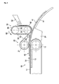
- a liner removal unit is shown.
- a stripper wheel 31 is provided for stripping off the liner 42 of a balancing weight body 41. It is rotating in direction 60 which is the same as the direction of movement 14 of the balancing weight.
- the speed of rotation is similar to the speed of movement of the balancing weight. Preferably, the speed of rotation is slightly higher.
- the stripper wheel has teeth which interact with the liner 41 and 42, and pull it away from the balancing weight.
- An aspirator 32 or a similar vacuum cleaning device further removes the liner 42 from the stripper wheel 31.
- the pressure device almost preferably a pressure roller 20 is provided.
- Such a pressure roller may be a single roller. Instead, here a pressure belt 23 is driven by a pressure pulley 21 and diverted via auxiliary pulley 22. Here, pressure builds up between the pressure roller 20 and pressure plate 24. Pressure roller 20 may be used for precision control of the speed of motion of the balancing weight 40, which therefore can precisely be adapted to the speed of the stripper wheel 31 or stripper belt 33. Pressure to the balancing weights may also be asserted by the stripper wheel or its shaft, which may bend the balancing weight into a desired radius. The balancing weight is further guided by a sliding surface 51. The balancing weight is fed into the liner removal unit by a belt conveyer 10 comprising of a belt 11, a conveyer pulley 12, and a support plate 13.
- FIG. 2 shows a liner removal unit comparable to the unit shown in the previous Figure 1 .
- the main difference is that the stripper wheel 31 is replaced by a stripper belt 33.
- the stripper belt 33 has teeth 36, which pull off the liner from the balancing weight.
- the stripper belt is moved by two stripper pulleys 34, 35.
- a balancing weight body is made of a metal or a metal-plastic composition providing mass, and therefore taking the function of the weight.
- an adhesive tape 43 is provided for fixing the balancing weight to a rim.
- the adhesive tape is covered by a liner 42 which must be peeled off before applying the balancing weight to a rim.
- FIG 4 shows the adhesive tape in detail.
- the liner 42 is stiffer than the adhesive tape itself, while the adhesive tape consists of a comparatively elastic material.
- the teeth of the stripper wheel or stripper belt penetrate through liner 42, they also penetrate into adhesive tape 43. Due to the elastic nature of this material, the teeth will make small cuts into this material instead of lifting the adhesive tape of the balancing weight body 41.
- the liner 42 which is comparatively stiff, cannot completely be cut by the teeth, and therefore sticks to the teeth and can be removed.
- Figure 5 shows a balancing weight 40 which is divided in a plurality of sections which can be separated as required.
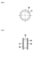
- a stripper wheel is shown in a front view.
- a first wheel disk 37 and a second wheel disk 38 both having teeth 36, are connected by a shaft 39 to rotate synchronously.
- a shaft 39 may have a diameter slightly smaller than the wheel disks to prevent a deeper penetration of the wheel disks into the adhesive tape.
Landscapes
- Engineering & Computer Science (AREA)
- Physics & Mathematics (AREA)
- General Engineering & Computer Science (AREA)
- Acoustics & Sound (AREA)
- Aviation & Aerospace Engineering (AREA)
- Mechanical Engineering (AREA)
- General Physics & Mathematics (AREA)
- Container, Conveyance, Adherence, Positioning, Of Wafer (AREA)
- Mechanical Treatment Of Semiconductor (AREA)
- Coating Apparatus (AREA)
- Cleaning In General (AREA)
Description
- The invention relates to methods and devices for dispensing weights used in vehicle ballasting applications, in particular for dispensing weights used in balancing automobile or other vehicle wheels.
- In automotive wheel balancing, individual wheel balancing weights are applied to specific positions of a rim. Basically, two types of balancing weight are used. The first kind is a balancing weight which is attached by a clamp, as disclosed in the European patent
EP 1 613 876 B1 , while the second kind is fixed by means of a self-adhesive tape, as disclosed inUS patent 6,364,421 B1 . - Both kinds of balancing weights are available in a plurality of sizes, resulting in different weights. When balancing a vehicle wheel, the correct size of balancing weight is selected and attached to the rim. Most balancing weights are supplied as bulk material in boxes, from which the required number of weights is manually taken.
- This allows for a simple, comparatively cheap supply of balancing weights. The drawback is that the person who is taking the weights from the box may take a wrong weight, and therefore a further step of balancing is required. Furthermore, the process of taking the weights can hardly be automated. Therefore, other solutions as disclosed in
WO 2008/103651 A1 - The problem to be solved by the invention is to strip off the liner from the adhesive tape of the balancing weights without damaging the adhesive tape and further without damaging the metal surface of the balancing weight. Furthermore, peeling-off should be done automatically in large volumes for low costs. It should be reliable without residing fractions of the liner on the adhesive tape.
- In a preferred embodiment of the invention, the liner is removed by a stripper wheel which rotates over the metal surface of the balancing weight, in a close proximity to be in contact with the liner but not with the metal surface of the balancing weight. Preferably, the stripper wheel rotates at a speed similar to the speed of movement of the balancing weight. Most preferably, the rotation speed of the stripper wheel is slightly higher than the speed of movement of the balancing weight.
- It is further preferred, if means for precise guiding of the balancing weight are provided. This improves reliability and repeatability of the stripping process and further prevents the stripper wheel to touch the metal surface of the balancing weight. Such means for guiding the balancing weight may be a pressure roller. Such a pressure roller may press the balancing weight against a surface which is further referred to as pressure plate. The pressure roller may be a single role or a belt-conveyer-like assembly having at least one, preferably two pulleys for moving the belt. Furthermore, an aspirator or a vacuum cleaning device may be provided for removing the liner from the stripper wheel.
- In a further embodiment of the invention, instead of the stripper wheel, a stripper belt may be used. It may be driven by at least one, preferably two stripper pulleys. Instead of a wheel or a belt, any other device having teeth at its outside and rotating with a speed similar to the speed of movement of the balancing weight may be used. Preferably, the stripper wheel or stripper pulley has sawtooth-like teeth, which are rotating in the direction of rotation, the direction of movement of the balancing weight.
- In another embodiment, the direction of rotation of the stripper wheel or stripper pulley may be reversed together with a reverse order of the teeth, resulting in stripping off the liner before the stripping wheel or belt.
- It is further preferred, if for supplying balancing weights to the liner removal unit, a belt conveyer is provided. Such a belt conveyer may bring up the force to push a balancing weight through the liner removal unit under the stripper wheel and/or stripper belt.
- In a further embodiment, a plurality of stripper wheels or belts may be provided either in parallel and/or one after the other.
- In a further embodiment of the invention, means for adjusting the stripper wheel or stripper belt in relation to the balancing weight may be provided. This may compensate for tolerances in the thickness of the balancing weight. The adjustment may be done by spring loading the stripper wheel or stripper belt, and therefore asserting a predetermined force on the balancing weight. An alternative embodiment would be to use a stripper wheel or stripper belt having a comparatively broad surface and small teeth on it, whereas the surface is smoothly lying on the surface of the liner, while the teeth penetrate into the liner. The surface may also be made of elastic material to perfectly adapt to deviations in the surface of the liner. An alternate embodiment would be to couple the stripper wheel or stripper belt with the pressure roller or at least one of the pressure pulleys. When a balancing weight with a certain thickness is guided through the
pressure roller 20, the pressure roller is lifted to height of the balancing weight, also causing the stripper wheel or stripper belt to be lifted to the same height. This may be done by some electronic controlling or by simple mechanical coupling. - The advantage of the embodiments is that the liner can be removed reliably. Furthermore, the liner may be removed at comparatively high speeds. This design allows comparatively small tolerances of the stripper wheel and/or stripper belt and means for guiding the balancing weight, which results in a comparatively small damage of the adhesive tape under the liner. Furthermore, a damage of the surface of the balancing weight can be completely avoided. This surface must not be damaged as corrosion may occur, starting at damaged sections.
- In the following the invention will be described by way of example, without limitation of the general inventive concept, on examples of embodiment with reference to the drawings.
-
Figure 1 shows a liner removal unit. -
Figure 2 shows a liner removal unit with a stripper belt. -
Figure 3 shows a balancing weight. -
Figure 4 shows an adhesive tape in detail. -
Figure 5 shows a balancing weight. -
Figure 6 shows a stripper wheel in a side view. -
Figure 7 shows a stripper wheel in a front view. - In
Figure 1 , a liner removal unit is shown. For stripping off theliner 42 of a balancingweight body 41, astripper wheel 31 is provided. It is rotating indirection 60 which is the same as the direction ofmovement 14 of the balancing weight. The speed of rotation is similar to the speed of movement of the balancing weight. Preferably, the speed of rotation is slightly higher. The stripper wheel has teeth which interact with theliner aspirator 32 or a similar vacuum cleaning device further removes theliner 42 from thestripper wheel 31. To prevent the balancing weight from being lifted up by slightly sticking to the liner, preferably the pressure device, almost preferably apressure roller 20 is provided. Such a pressure roller may be a single roller. Instead, here apressure belt 23 is driven by apressure pulley 21 and diverted viaauxiliary pulley 22. Here, pressure builds up between thepressure roller 20 andpressure plate 24.Pressure roller 20 may be used for precision control of the speed of motion of the balancingweight 40, which therefore can precisely be adapted to the speed of thestripper wheel 31 orstripper belt 33. Pressure to the balancing weights may also be asserted by the stripper wheel or its shaft, which may bend the balancing weight into a desired radius. The balancing weight is further guided by a slidingsurface 51. The balancing weight is fed into the liner removal unit by abelt conveyer 10 comprising of abelt 11, aconveyer pulley 12, and asupport plate 13. -
Figure 2 shows a liner removal unit comparable to the unit shown in the previousFigure 1 . The main difference is that thestripper wheel 31 is replaced by astripper belt 33. Here, thestripper belt 33 hasteeth 36, which pull off the liner from the balancing weight. The stripper belt is moved by two stripper pulleys 34, 35. - In
Figure 3 , a balancing weight is shown. A balancing weight body is made of a metal or a metal-plastic composition providing mass, and therefore taking the function of the weight. For fixing the balancing weight to a rim, anadhesive tape 43 is provided. For protection, the adhesive tape is covered by aliner 42 which must be peeled off before applying the balancing weight to a rim. -
Figure 4 shows the adhesive tape in detail. Theliner 42 is stiffer than the adhesive tape itself, while the adhesive tape consists of a comparatively elastic material. When the teeth of the stripper wheel or stripper belt penetrate throughliner 42, they also penetrate intoadhesive tape 43. Due to the elastic nature of this material, the teeth will make small cuts into this material instead of lifting the adhesive tape of the balancingweight body 41. Theliner 42 which is comparatively stiff, cannot completely be cut by the teeth, and therefore sticks to the teeth and can be removed. -
Figure 5 shows a balancingweight 40 which is divided in a plurality of sections which can be separated as required. - In
Figure 6 , a stripper wheel withteeth 36 is shown in a side view. - In
Figure 7 , a stripper wheel is shown in a front view. Here, afirst wheel disk 37 and asecond wheel disk 38, both havingteeth 36, are connected by ashaft 39 to rotate synchronously. It is obvious that any other number ofwheel disks shaft 39 may have a diameter slightly smaller than the wheel disks to prevent a deeper penetration of the wheel disks into the adhesive tape. -
- 10
- belt conveyer
- 11
- belt
- 12
- conveyer pulley
- 13
- support plate
- 14
- direction of movement
- 20
- pressure roller
- 21
- pressure pulley
- 22
- auxiliary pulley
- 23
- pressure belt
- 24
- pressure plate
- 30
- stripper
- 31
- stripper wheel
- 32
- aspirator
- 33
- stripper belt
- 34, 35
- stripper pulley
- 36
- teeth
- 37, 38
- wheel disk
- 39
- shaft
- 40
- balancing weight
- 41
- balancing weight body
- 42
- liner
- 43
- adhesive tape
- 51
- sliding surface
- 60
- direction of rotation
Claims (6)
- Apparatus and method for removing the liner of a self-adhesive balancing weight, comprising of- means for transporting the balancing weight (40) into a first direction (14);- at least one stripper wheel (31) or stripper belt (33), comprising a plurality of teeth (36) rotating in close proximity to the surface of the balancing weight for interacting and pulling away the liner (42) from the surface of the balancing weight (40).
- Apparatus according to claim 1,
characterized in that
the direction of movement of the stripper wheel (31) and/or stripper belt (33) is the same as the first direction (14). - Apparatus according to any one of the preceding claims,
characterized in that
the rotating speed of the stripper wheel (31) and/or stripper belt (33) is the same as the speed of movement of the balancing weight (40). - Apparatus according to claims 1 or 2,
characterized in that
the speed of rotation of the stripper wheel (31) or the stripper belt (33) is slightly higher than the speed of movement of the balancing weight (40). - Apparatus according to any one of the preceding claims,
characterized in that
a pressure roller is provided for pressing the balancing weight to a surface (24) opposed to the stripper wheel (31) or stripper belt (33). - Apparatus according to any one of the preceding claims,
characterized in that
a belt conveyer (10) is provided for supplying a balancing weight to the stripper wheel (31) or stripper belt (33).
Priority Applications (3)
| Application Number | Priority Date | Filing Date | Title |
|---|---|---|---|
| EP12176445.0A EP2642158B1 (en) | 2012-03-20 | 2012-07-13 | Apparatus and method for self adhesive balancing weight liner removal |
| PCT/EP2013/053593 WO2013139558A1 (en) | 2012-03-20 | 2013-02-22 | Apparatus and method for self adhesive balancing weight liner removal |
| US14/473,238 US9421749B2 (en) | 2012-03-20 | 2014-08-29 | Apparatus and method for self adhesive balancing weight liner removal |
Applications Claiming Priority (2)
| Application Number | Priority Date | Filing Date | Title |
|---|---|---|---|
| EP12160444 | 2012-03-20 | ||
| EP12176445.0A EP2642158B1 (en) | 2012-03-20 | 2012-07-13 | Apparatus and method for self adhesive balancing weight liner removal |
Publications (2)
| Publication Number | Publication Date |
|---|---|
| EP2642158A1 EP2642158A1 (en) | 2013-09-25 |
| EP2642158B1 true EP2642158B1 (en) | 2014-11-19 |
Family
ID=46545263
Family Applications (1)
| Application Number | Title | Priority Date | Filing Date |
|---|---|---|---|
| EP12176445.0A Not-in-force EP2642158B1 (en) | 2012-03-20 | 2012-07-13 | Apparatus and method for self adhesive balancing weight liner removal |
Country Status (4)
| Country | Link |
|---|---|
| US (1) | US9421749B2 (en) |
| EP (1) | EP2642158B1 (en) |
| ES (1) | ES2530369T3 (en) |
| WO (1) | WO2013139558A1 (en) |
Families Citing this family (7)
| Publication number | Priority date | Publication date | Assignee | Title |
|---|---|---|---|---|
| KR101818473B1 (en) * | 2011-11-30 | 2018-01-16 | 엘지디스플레이 주식회사 | Apparatus and Method for peeling protection film |
| WO2015134426A1 (en) | 2014-03-03 | 2015-09-11 | 3M Innovative Properties Company | Wheel balancing weights, and methods and devices for using same |
| US10215657B2 (en) * | 2015-03-30 | 2019-02-26 | Android Industries Llc | Automated balance-weight applicator |
| CA2932206A1 (en) | 2016-02-29 | 2017-08-29 | Plombco Inc. | Spool assembly and method of use thereof |
| CA2922039A1 (en) * | 2016-02-29 | 2017-08-29 | Plombco Inc. | Balancing weight application machine and method of use thereof |
| CN106913257B (en) * | 2017-03-23 | 2018-11-02 | 深圳饭来科技有限公司 | Dyestripping batch charging mechanism |
| TWI755244B (en) * | 2021-01-06 | 2022-02-11 | 志聖工業股份有限公司 | Laminator and film peeler thereof |
Family Cites Families (18)
| Publication number | Priority date | Publication date | Assignee | Title |
|---|---|---|---|---|
| US4405401A (en) * | 1981-07-15 | 1983-09-20 | Stahl Ted A | Thermoplastic labeling and method of making same |
| JPH06171823A (en) * | 1992-12-09 | 1994-06-21 | Canon Inc | Remover of protection film for dry film resist |
| JP3305192B2 (en) * | 1995-03-15 | 2002-07-22 | セイコーエプソン株式会社 | Adhesive transfer method and transfer device |
| US6364421B1 (en) | 1998-12-09 | 2002-04-02 | Perfect Equipment Company Llc | Wheel balancing weights |
| US6500298B1 (en) * | 2000-01-14 | 2002-12-31 | Kevin P. Wright | Stripping machine and method |
| JP2002144344A (en) * | 2000-11-16 | 2002-05-21 | Matsushita Electric Ind Co Ltd | Method for recovering foamed resin and foaming gas, and method for dismantling refrigerator |
| US6797103B2 (en) * | 2001-03-12 | 2004-09-28 | Mikkelsen Graphic Engineering Inc. | Automatic waste-area removal method and apparatus |
| US6547338B2 (en) * | 2001-03-26 | 2003-04-15 | Illinois Tool Works Inc. | Individual segment adhesive correction weight |
| US6616089B2 (en) * | 2001-04-24 | 2003-09-09 | Illinois Tool Works Inc. | System and method for dispensing adhesive imbalance correction weight |
| CA2522063C (en) | 2003-04-11 | 2010-07-27 | Franken Industrie Werke Ernst Stenz Gmbh & Co. Kg | Balancing weight for vehicle wheels, comprising a concavely or convexly curved contact face, and method for the production thereof |
| US7044561B2 (en) * | 2003-11-18 | 2006-05-16 | Halko Manufacturing Co. | Adhesive wheel balancing weights having a serrated backing strip |
| TWI336603B (en) * | 2004-12-03 | 2011-01-21 | Ngk Spark Plug Co | Method and apparatus for producing a wiring board, including film-peeling |
| WO2007094277A1 (en) * | 2006-02-13 | 2007-08-23 | Tokuyama Corporation | Stripping liquid for use in separating paper from plaster/paper laminate |
| US7655109B2 (en) * | 2006-03-06 | 2010-02-02 | Herbert C. Manners | Floor covering lifting and removal hand tool |
| US8137417B2 (en) * | 2006-09-29 | 2012-03-20 | Semiconductor Energy Laboratory Co., Ltd. | Peeling apparatus and manufacturing apparatus of semiconductor device |
| DE102007014461B4 (en) * | 2007-01-02 | 2012-03-29 | Schenck Rotec Gmbh | Method and device for unbalance compensation of vehicle wheels |
| ES2560103T3 (en) | 2007-02-19 | 2016-02-17 | 3M Innovative Properties Company | Apparatus and method for distributing weighted weights of a vehicle |
| EP2118669B1 (en) * | 2007-03-09 | 2013-01-30 | Nexus Biosystems, Inc., | Device and method for removing a peelable seal |
-
2012
- 2012-07-13 ES ES12176445T patent/ES2530369T3/en active Active
- 2012-07-13 EP EP12176445.0A patent/EP2642158B1/en not_active Not-in-force
-
2013
- 2013-02-22 WO PCT/EP2013/053593 patent/WO2013139558A1/en not_active Ceased
-
2014
- 2014-08-29 US US14/473,238 patent/US9421749B2/en not_active Expired - Fee Related
Also Published As
| Publication number | Publication date |
|---|---|
| ES2530369T3 (en) | 2015-03-02 |
| US20140367050A1 (en) | 2014-12-18 |
| WO2013139558A1 (en) | 2013-09-26 |
| US9421749B2 (en) | 2016-08-23 |
| EP2642158A1 (en) | 2013-09-25 |
Similar Documents
| Publication | Publication Date | Title |
|---|---|---|
| US9421749B2 (en) | Apparatus and method for self adhesive balancing weight liner removal | |
| JP4895240B2 (en) | Film sticking device and sticking method | |
| JP5345621B2 (en) | Tape removing device and process used for automatic composite tape pasting device | |
| CN106553383B (en) | Manufacturing apparatus of laminated label body | |
| KR20060125720A (en) | Mounting device and mounting method | |
| KR20060042248A (en) | Bonding method of sheet medium and device using same | |
| US10557520B2 (en) | Automatic dispenser for balancing weights | |
| EP3435145A1 (en) | Device and method for removing film from a display device | |
| JP2025532938A (en) | Application device with refilling cassette | |
| JP2012017204A (en) | Sticking device and sticking method of adhesive tape | |
| JP5323549B2 (en) | Adhesive tape terminal processing method and processing apparatus therefor | |
| JP6559032B2 (en) | Support apparatus and support method | |
| US7913736B2 (en) | Apparatus and method for affixing adhesive tape | |
| KR101477509B1 (en) | Film removing apparatus | |
| CN107867460A (en) | A kind of electronic tag is implanted into equipment | |
| CN115196131B (en) | Display screen detection equipment capable of recycling film materials | |
| CN117140805A (en) | Tear sticky tape mechanism and tear sticky tape equipment | |
| CN115648328A (en) | EVA sheet cutting device with waste material collecting mechanism and collecting method thereof | |
| JPH07291247A (en) | Labeling machine | |
| CN220197879U (en) | Glue pressing mechanism and glue paper cutting equipment | |
| US11766841B2 (en) | Tape layup systems and associated methods | |
| JP6349193B2 (en) | Sheet peeling apparatus and peeling method | |
| EP3247645B1 (en) | Labelling apparatus and method | |
| JP4083140B2 (en) | Coated film removing apparatus for articles and method therefor | |
| EP3415789B1 (en) | Dispenser for wheel balancing weights |
Legal Events
| Date | Code | Title | Description |
|---|---|---|---|
| PUAI | Public reference made under article 153(3) epc to a published international application that has entered the european phase |
Free format text: ORIGINAL CODE: 0009012 |
|
| AK | Designated contracting states |
Kind code of ref document: A1 Designated state(s): AL AT BE BG CH CY CZ DE DK EE ES FI FR GB GR HR HU IE IS IT LI LT LU LV MC MK MT NL NO PL PT RO RS SE SI SK SM TR |
|
| AX | Request for extension of the european patent |
Extension state: BA ME |
|
| 17P | Request for examination filed |
Effective date: 20131021 |
|
| RBV | Designated contracting states (corrected) |
Designated state(s): AL AT BE BG CH CY CZ DE DK EE ES FI FR GB GR HR HU IE IS IT LI LT LU LV MC MK MT NL NO PL PT RO RS SE SI SK SM TR |
|
| GRAP | Despatch of communication of intention to grant a patent |
Free format text: ORIGINAL CODE: EPIDOSNIGR1 |
|
| INTG | Intention to grant announced |
Effective date: 20140522 |
|
| RIN1 | Information on inventor provided before grant (corrected) |
Inventor name: BODE, FELIX |
|
| GRAS | Grant fee paid |
Free format text: ORIGINAL CODE: EPIDOSNIGR3 |
|
| GRAA | (expected) grant |
Free format text: ORIGINAL CODE: 0009210 |
|
| RIN1 | Information on inventor provided before grant (corrected) |
Inventor name: BUERGEL, HANS-ULRICH |
|
| AK | Designated contracting states |
Kind code of ref document: B1 Designated state(s): AL AT BE BG CH CY CZ DE DK EE ES FI FR GB GR HR HU IE IS IT LI LT LU LV MC MK MT NL NO PL PT RO RS SE SI SK SM TR |
|
| REG | Reference to a national code |
Ref country code: GB Ref legal event code: FG4D |
|
| RIN1 | Information on inventor provided before grant (corrected) |
Inventor name: BUERGEL, HANS-ULRICH |
|
| REG | Reference to a national code |
Ref country code: CH Ref legal event code: EP |
|
| REG | Reference to a national code |
Ref country code: AT Ref legal event code: REF Ref document number: 697217 Country of ref document: AT Kind code of ref document: T Effective date: 20141215 |
|
| REG | Reference to a national code |
Ref country code: IE Ref legal event code: FG4D |
|
| REG | Reference to a national code |
Ref country code: DE Ref legal event code: R096 Ref document number: 602012003846 Country of ref document: DE Effective date: 20141231 |
|
| REG | Reference to a national code |
Ref country code: ES Ref legal event code: FG2A Ref document number: 2530369 Country of ref document: ES Kind code of ref document: T3 Effective date: 20150302 |
|
| REG | Reference to a national code |
Ref country code: SE Ref legal event code: TRGR |
|
| REG | Reference to a national code |
Ref country code: NL Ref legal event code: VDEP Effective date: 20141119 |
|
| REG | Reference to a national code |
Ref country code: AT Ref legal event code: MK05 Ref document number: 697217 Country of ref document: AT Kind code of ref document: T Effective date: 20141119 |
|
| REG | Reference to a national code |
Ref country code: LT Ref legal event code: MG4D |
|
| PG25 | Lapsed in a contracting state [announced via postgrant information from national office to epo] |
Ref country code: PT Free format text: LAPSE BECAUSE OF FAILURE TO SUBMIT A TRANSLATION OF THE DESCRIPTION OR TO PAY THE FEE WITHIN THE PRESCRIBED TIME-LIMIT Effective date: 20150319 Ref country code: FI Free format text: LAPSE BECAUSE OF FAILURE TO SUBMIT A TRANSLATION OF THE DESCRIPTION OR TO PAY THE FEE WITHIN THE PRESCRIBED TIME-LIMIT Effective date: 20141119 Ref country code: NO Free format text: LAPSE BECAUSE OF FAILURE TO SUBMIT A TRANSLATION OF THE DESCRIPTION OR TO PAY THE FEE WITHIN THE PRESCRIBED TIME-LIMIT Effective date: 20150219 Ref country code: NL Free format text: LAPSE BECAUSE OF FAILURE TO SUBMIT A TRANSLATION OF THE DESCRIPTION OR TO PAY THE FEE WITHIN THE PRESCRIBED TIME-LIMIT Effective date: 20141119 Ref country code: IS Free format text: LAPSE BECAUSE OF FAILURE TO SUBMIT A TRANSLATION OF THE DESCRIPTION OR TO PAY THE FEE WITHIN THE PRESCRIBED TIME-LIMIT Effective date: 20150319 Ref country code: LT Free format text: LAPSE BECAUSE OF FAILURE TO SUBMIT A TRANSLATION OF THE DESCRIPTION OR TO PAY THE FEE WITHIN THE PRESCRIBED TIME-LIMIT Effective date: 20141119 |
|
| PG25 | Lapsed in a contracting state [announced via postgrant information from national office to epo] |
Ref country code: HR Free format text: LAPSE BECAUSE OF FAILURE TO SUBMIT A TRANSLATION OF THE DESCRIPTION OR TO PAY THE FEE WITHIN THE PRESCRIBED TIME-LIMIT Effective date: 20141119 Ref country code: RS Free format text: LAPSE BECAUSE OF FAILURE TO SUBMIT A TRANSLATION OF THE DESCRIPTION OR TO PAY THE FEE WITHIN THE PRESCRIBED TIME-LIMIT Effective date: 20141119 Ref country code: CY Free format text: LAPSE BECAUSE OF FAILURE TO SUBMIT A TRANSLATION OF THE DESCRIPTION OR TO PAY THE FEE WITHIN THE PRESCRIBED TIME-LIMIT Effective date: 20141119 Ref country code: GR Free format text: LAPSE BECAUSE OF FAILURE TO SUBMIT A TRANSLATION OF THE DESCRIPTION OR TO PAY THE FEE WITHIN THE PRESCRIBED TIME-LIMIT Effective date: 20150220 Ref country code: AT Free format text: LAPSE BECAUSE OF FAILURE TO SUBMIT A TRANSLATION OF THE DESCRIPTION OR TO PAY THE FEE WITHIN THE PRESCRIBED TIME-LIMIT Effective date: 20141119 Ref country code: PL Free format text: LAPSE BECAUSE OF FAILURE TO SUBMIT A TRANSLATION OF THE DESCRIPTION OR TO PAY THE FEE WITHIN THE PRESCRIBED TIME-LIMIT Effective date: 20141119 Ref country code: LV Free format text: LAPSE BECAUSE OF FAILURE TO SUBMIT A TRANSLATION OF THE DESCRIPTION OR TO PAY THE FEE WITHIN THE PRESCRIBED TIME-LIMIT Effective date: 20141119 |
|
| PG25 | Lapsed in a contracting state [announced via postgrant information from national office to epo] |
Ref country code: RO Free format text: LAPSE BECAUSE OF FAILURE TO SUBMIT A TRANSLATION OF THE DESCRIPTION OR TO PAY THE FEE WITHIN THE PRESCRIBED TIME-LIMIT Effective date: 20141119 Ref country code: DK Free format text: LAPSE BECAUSE OF FAILURE TO SUBMIT A TRANSLATION OF THE DESCRIPTION OR TO PAY THE FEE WITHIN THE PRESCRIBED TIME-LIMIT Effective date: 20141119 Ref country code: SK Free format text: LAPSE BECAUSE OF FAILURE TO SUBMIT A TRANSLATION OF THE DESCRIPTION OR TO PAY THE FEE WITHIN THE PRESCRIBED TIME-LIMIT Effective date: 20141119 Ref country code: EE Free format text: LAPSE BECAUSE OF FAILURE TO SUBMIT A TRANSLATION OF THE DESCRIPTION OR TO PAY THE FEE WITHIN THE PRESCRIBED TIME-LIMIT Effective date: 20141119 |
|
| REG | Reference to a national code |
Ref country code: DE Ref legal event code: R097 Ref document number: 602012003846 Country of ref document: DE |
|
| PLBE | No opposition filed within time limit |
Free format text: ORIGINAL CODE: 0009261 |
|
| STAA | Information on the status of an ep patent application or granted ep patent |
Free format text: STATUS: NO OPPOSITION FILED WITHIN TIME LIMIT |
|
| 26N | No opposition filed |
Effective date: 20150820 |
|
| PG25 | Lapsed in a contracting state [announced via postgrant information from national office to epo] |
Ref country code: SI Free format text: LAPSE BECAUSE OF FAILURE TO SUBMIT A TRANSLATION OF THE DESCRIPTION OR TO PAY THE FEE WITHIN THE PRESCRIBED TIME-LIMIT Effective date: 20141119 Ref country code: MC Free format text: LAPSE BECAUSE OF FAILURE TO SUBMIT A TRANSLATION OF THE DESCRIPTION OR TO PAY THE FEE WITHIN THE PRESCRIBED TIME-LIMIT Effective date: 20141119 |
|
| REG | Reference to a national code |
Ref country code: CH Ref legal event code: PL |
|
| PG25 | Lapsed in a contracting state [announced via postgrant information from national office to epo] |
Ref country code: LU Free format text: LAPSE BECAUSE OF FAILURE TO SUBMIT A TRANSLATION OF THE DESCRIPTION OR TO PAY THE FEE WITHIN THE PRESCRIBED TIME-LIMIT Effective date: 20150713 |
|
| REG | Reference to a national code |
Ref country code: IE Ref legal event code: MM4A |
|
| PG25 | Lapsed in a contracting state [announced via postgrant information from national office to epo] |
Ref country code: LI Free format text: LAPSE BECAUSE OF NON-PAYMENT OF DUE FEES Effective date: 20150731 Ref country code: CH Free format text: LAPSE BECAUSE OF NON-PAYMENT OF DUE FEES Effective date: 20150731 |
|
| REG | Reference to a national code |
Ref country code: FR Ref legal event code: PLFP Year of fee payment: 5 |
|
| PG25 | Lapsed in a contracting state [announced via postgrant information from national office to epo] |
Ref country code: IE Free format text: LAPSE BECAUSE OF NON-PAYMENT OF DUE FEES Effective date: 20150713 |
|
| PGFP | Annual fee paid to national office [announced via postgrant information from national office to epo] |
Ref country code: IT Payment date: 20160721 Year of fee payment: 5 Ref country code: GB Payment date: 20160722 Year of fee payment: 5 |
|
| PGFP | Annual fee paid to national office [announced via postgrant information from national office to epo] |
Ref country code: SE Payment date: 20160721 Year of fee payment: 5 Ref country code: FR Payment date: 20160722 Year of fee payment: 5 |
|
| PGFP | Annual fee paid to national office [announced via postgrant information from national office to epo] |
Ref country code: ES Payment date: 20160722 Year of fee payment: 5 Ref country code: BE Payment date: 20160721 Year of fee payment: 5 |
|
| PG25 | Lapsed in a contracting state [announced via postgrant information from national office to epo] |
Ref country code: MT Free format text: LAPSE BECAUSE OF FAILURE TO SUBMIT A TRANSLATION OF THE DESCRIPTION OR TO PAY THE FEE WITHIN THE PRESCRIBED TIME-LIMIT Effective date: 20141119 |
|
| PG25 | Lapsed in a contracting state [announced via postgrant information from national office to epo] |
Ref country code: SM Free format text: LAPSE BECAUSE OF FAILURE TO SUBMIT A TRANSLATION OF THE DESCRIPTION OR TO PAY THE FEE WITHIN THE PRESCRIBED TIME-LIMIT Effective date: 20141119 Ref country code: HU Free format text: LAPSE BECAUSE OF FAILURE TO SUBMIT A TRANSLATION OF THE DESCRIPTION OR TO PAY THE FEE WITHIN THE PRESCRIBED TIME-LIMIT; INVALID AB INITIO Effective date: 20120713 Ref country code: BG Free format text: LAPSE BECAUSE OF FAILURE TO SUBMIT A TRANSLATION OF THE DESCRIPTION OR TO PAY THE FEE WITHIN THE PRESCRIBED TIME-LIMIT Effective date: 20141119 |
|
| PGFP | Annual fee paid to national office [announced via postgrant information from national office to epo] |
Ref country code: CZ Payment date: 20170704 Year of fee payment: 6 |
|
| REG | Reference to a national code |
Ref country code: SE Ref legal event code: EUG |
|
| GBPC | Gb: european patent ceased through non-payment of renewal fee |
Effective date: 20170713 |
|
| REG | Reference to a national code |
Ref country code: FR Ref legal event code: ST Effective date: 20180330 |
|
| PG25 | Lapsed in a contracting state [announced via postgrant information from national office to epo] |
Ref country code: GB Free format text: LAPSE BECAUSE OF NON-PAYMENT OF DUE FEES Effective date: 20170713 Ref country code: SE Free format text: LAPSE BECAUSE OF NON-PAYMENT OF DUE FEES Effective date: 20170714 |
|
| PG25 | Lapsed in a contracting state [announced via postgrant information from national office to epo] |
Ref country code: FR Free format text: LAPSE BECAUSE OF NON-PAYMENT OF DUE FEES Effective date: 20170731 |
|
| REG | Reference to a national code |
Ref country code: BE Ref legal event code: FP Effective date: 20150219 Ref country code: BE Ref legal event code: MM Effective date: 20170731 |
|
| PG25 | Lapsed in a contracting state [announced via postgrant information from national office to epo] |
Ref country code: MK Free format text: LAPSE BECAUSE OF FAILURE TO SUBMIT A TRANSLATION OF THE DESCRIPTION OR TO PAY THE FEE WITHIN THE PRESCRIBED TIME-LIMIT Effective date: 20141119 Ref country code: TR Free format text: LAPSE BECAUSE OF FAILURE TO SUBMIT A TRANSLATION OF THE DESCRIPTION OR TO PAY THE FEE WITHIN THE PRESCRIBED TIME-LIMIT Effective date: 20141119 |
|
| PG25 | Lapsed in a contracting state [announced via postgrant information from national office to epo] |
Ref country code: BE Free format text: LAPSE BECAUSE OF NON-PAYMENT OF DUE FEES Effective date: 20170731 Ref country code: IT Free format text: LAPSE BECAUSE OF NON-PAYMENT OF DUE FEES Effective date: 20170713 |
|
| REG | Reference to a national code |
Ref country code: ES Ref legal event code: FD2A Effective date: 20181025 |
|
| PG25 | Lapsed in a contracting state [announced via postgrant information from national office to epo] |
Ref country code: AL Free format text: LAPSE BECAUSE OF FAILURE TO SUBMIT A TRANSLATION OF THE DESCRIPTION OR TO PAY THE FEE WITHIN THE PRESCRIBED TIME-LIMIT Effective date: 20141119 |
|
| PGFP | Annual fee paid to national office [announced via postgrant information from national office to epo] |
Ref country code: DE Payment date: 20180730 Year of fee payment: 7 |
|
| PG25 | Lapsed in a contracting state [announced via postgrant information from national office to epo] |
Ref country code: ES Free format text: LAPSE BECAUSE OF NON-PAYMENT OF DUE FEES Effective date: 20170714 |
|
| PG25 | Lapsed in a contracting state [announced via postgrant information from national office to epo] |
Ref country code: CZ Free format text: LAPSE BECAUSE OF NON-PAYMENT OF DUE FEES Effective date: 20180713 |
|
| REG | Reference to a national code |
Ref country code: DE Ref legal event code: R119 Ref document number: 602012003846 Country of ref document: DE |
|
| PG25 | Lapsed in a contracting state [announced via postgrant information from national office to epo] |
Ref country code: DE Free format text: LAPSE BECAUSE OF NON-PAYMENT OF DUE FEES Effective date: 20200201 |