EP2642141A1 - Stabilizer link and method for manufacturing same - Google Patents
Stabilizer link and method for manufacturing same Download PDFInfo
- Publication number
- EP2642141A1 EP2642141A1 EP11841585.0A EP11841585A EP2642141A1 EP 2642141 A1 EP2642141 A1 EP 2642141A1 EP 11841585 A EP11841585 A EP 11841585A EP 2642141 A1 EP2642141 A1 EP 2642141A1
- Authority
- EP
- European Patent Office
- Prior art keywords
- ball
- housing
- main body
- ball seat
- fixing
- Prior art date
- Legal status (The legal status is an assumption and is not a legal conclusion. Google has not performed a legal analysis and makes no representation as to the accuracy of the status listed.)
- Granted
Links
Images



Classifications
-
- B—PERFORMING OPERATIONS; TRANSPORTING
- B29—WORKING OF PLASTICS; WORKING OF SUBSTANCES IN A PLASTIC STATE IN GENERAL
- B29C—SHAPING OR JOINING OF PLASTICS; SHAPING OF MATERIAL IN A PLASTIC STATE, NOT OTHERWISE PROVIDED FOR; AFTER-TREATMENT OF THE SHAPED PRODUCTS, e.g. REPAIRING
- B29C45/00—Injection moulding, i.e. forcing the required volume of moulding material through a nozzle into a closed mould; Apparatus therefor
- B29C45/14—Injection moulding, i.e. forcing the required volume of moulding material through a nozzle into a closed mould; Apparatus therefor incorporating preformed parts or layers, e.g. injection moulding around inserts or for coating articles
- B29C45/14467—Joining articles or parts of a single article
-
- B—PERFORMING OPERATIONS; TRANSPORTING
- B60—VEHICLES IN GENERAL
- B60G—VEHICLE SUSPENSION ARRANGEMENTS
- B60G7/00—Pivoted suspension arms; Accessories thereof
- B60G7/02—Attaching arms to sprung part of vehicle
-
- B—PERFORMING OPERATIONS; TRANSPORTING
- B60—VEHICLES IN GENERAL
- B60G—VEHICLE SUSPENSION ARRANGEMENTS
- B60G21/00—Interconnection systems for two or more resiliently-suspended wheels, e.g. for stabilising a vehicle body with respect to acceleration, deceleration or centrifugal forces
- B60G21/02—Interconnection systems for two or more resiliently-suspended wheels, e.g. for stabilising a vehicle body with respect to acceleration, deceleration or centrifugal forces permanently interconnected
- B60G21/04—Interconnection systems for two or more resiliently-suspended wheels, e.g. for stabilising a vehicle body with respect to acceleration, deceleration or centrifugal forces permanently interconnected mechanically
- B60G21/05—Interconnection systems for two or more resiliently-suspended wheels, e.g. for stabilising a vehicle body with respect to acceleration, deceleration or centrifugal forces permanently interconnected mechanically between wheels on the same axle but on different sides of the vehicle, i.e. the left and right wheel suspensions being interconnected
- B60G21/055—Stabiliser bars
-
- B—PERFORMING OPERATIONS; TRANSPORTING
- B60—VEHICLES IN GENERAL
- B60G—VEHICLE SUSPENSION ARRANGEMENTS
- B60G7/00—Pivoted suspension arms; Accessories thereof
- B60G7/005—Ball joints
-
- F—MECHANICAL ENGINEERING; LIGHTING; HEATING; WEAPONS; BLASTING
- F16—ENGINEERING ELEMENTS AND UNITS; GENERAL MEASURES FOR PRODUCING AND MAINTAINING EFFECTIVE FUNCTIONING OF MACHINES OR INSTALLATIONS; THERMAL INSULATION IN GENERAL
- F16C—SHAFTS; FLEXIBLE SHAFTS; ELEMENTS OR CRANKSHAFT MECHANISMS; ROTARY BODIES OTHER THAN GEARING ELEMENTS; BEARINGS
- F16C11/00—Pivots; Pivotal connections
- F16C11/04—Pivotal connections
- F16C11/06—Ball-joints; Other joints having more than one degree of angular freedom, i.e. universal joints
-
- F—MECHANICAL ENGINEERING; LIGHTING; HEATING; WEAPONS; BLASTING
- F16—ENGINEERING ELEMENTS AND UNITS; GENERAL MEASURES FOR PRODUCING AND MAINTAINING EFFECTIVE FUNCTIONING OF MACHINES OR INSTALLATIONS; THERMAL INSULATION IN GENERAL
- F16C—SHAFTS; FLEXIBLE SHAFTS; ELEMENTS OR CRANKSHAFT MECHANISMS; ROTARY BODIES OTHER THAN GEARING ELEMENTS; BEARINGS
- F16C11/00—Pivots; Pivotal connections
- F16C11/04—Pivotal connections
- F16C11/06—Ball-joints; Other joints having more than one degree of angular freedom, i.e. universal joints
- F16C11/0619—Ball-joints; Other joints having more than one degree of angular freedom, i.e. universal joints the female part comprising a blind socket receiving the male part
- F16C11/0623—Construction or details of the socket member
- F16C11/0628—Construction or details of the socket member with linings
- F16C11/0633—Construction or details of the socket member with linings the linings being made of plastics
- F16C11/0638—Construction or details of the socket member with linings the linings being made of plastics characterised by geometrical details
-
- F—MECHANICAL ENGINEERING; LIGHTING; HEATING; WEAPONS; BLASTING
- F16—ENGINEERING ELEMENTS AND UNITS; GENERAL MEASURES FOR PRODUCING AND MAINTAINING EFFECTIVE FUNCTIONING OF MACHINES OR INSTALLATIONS; THERMAL INSULATION IN GENERAL
- F16C—SHAFTS; FLEXIBLE SHAFTS; ELEMENTS OR CRANKSHAFT MECHANISMS; ROTARY BODIES OTHER THAN GEARING ELEMENTS; BEARINGS
- F16C11/00—Pivots; Pivotal connections
- F16C11/04—Pivotal connections
- F16C11/06—Ball-joints; Other joints having more than one degree of angular freedom, i.e. universal joints
- F16C11/0685—Manufacture of ball-joints and parts thereof, e.g. assembly of ball-joints
-
- B—PERFORMING OPERATIONS; TRANSPORTING
- B29—WORKING OF PLASTICS; WORKING OF SUBSTANCES IN A PLASTIC STATE IN GENERAL
- B29C—SHAPING OR JOINING OF PLASTICS; SHAPING OF MATERIAL IN A PLASTIC STATE, NOT OTHERWISE PROVIDED FOR; AFTER-TREATMENT OF THE SHAPED PRODUCTS, e.g. REPAIRING
- B29C33/00—Moulds or cores; Details thereof or accessories therefor
- B29C33/10—Moulds or cores; Details thereof or accessories therefor with incorporated venting means
-
- B—PERFORMING OPERATIONS; TRANSPORTING
- B29—WORKING OF PLASTICS; WORKING OF SUBSTANCES IN A PLASTIC STATE IN GENERAL
- B29K—INDEXING SCHEME ASSOCIATED WITH SUBCLASSES B29B, B29C OR B29D, RELATING TO MOULDING MATERIALS OR TO MATERIALS FOR MOULDS, REINFORCEMENTS, FILLERS OR PREFORMED PARTS, e.g. INSERTS
- B29K2105/00—Condition, form or state of moulded material or of the material to be shaped
- B29K2105/06—Condition, form or state of moulded material or of the material to be shaped containing reinforcements, fillers or inserts
-
- B—PERFORMING OPERATIONS; TRANSPORTING
- B29—WORKING OF PLASTICS; WORKING OF SUBSTANCES IN A PLASTIC STATE IN GENERAL
- B29K—INDEXING SCHEME ASSOCIATED WITH SUBCLASSES B29B, B29C OR B29D, RELATING TO MOULDING MATERIALS OR TO MATERIALS FOR MOULDS, REINFORCEMENTS, FILLERS OR PREFORMED PARTS, e.g. INSERTS
- B29K2105/00—Condition, form or state of moulded material or of the material to be shaped
- B29K2105/06—Condition, form or state of moulded material or of the material to be shaped containing reinforcements, fillers or inserts
- B29K2105/12—Condition, form or state of moulded material or of the material to be shaped containing reinforcements, fillers or inserts of short lengths, e.g. chopped filaments, staple fibres or bristles
-
- B—PERFORMING OPERATIONS; TRANSPORTING
- B29—WORKING OF PLASTICS; WORKING OF SUBSTANCES IN A PLASTIC STATE IN GENERAL
- B29L—INDEXING SCHEME ASSOCIATED WITH SUBCLASS B29C, RELATING TO PARTICULAR ARTICLES
- B29L2031/00—Other particular articles
- B29L2031/30—Vehicles, e.g. ships or aircraft, or body parts thereof
-
- B—PERFORMING OPERATIONS; TRANSPORTING
- B60—VEHICLES IN GENERAL
- B60G—VEHICLE SUSPENSION ARRANGEMENTS
- B60G2204/00—Indexing codes related to suspensions per se or to auxiliary parts
- B60G2204/10—Mounting of suspension elements
- B60G2204/12—Mounting of springs or dampers
- B60G2204/122—Mounting of torsion springs
- B60G2204/1224—End mounts of stabiliser on wheel suspension
-
- B—PERFORMING OPERATIONS; TRANSPORTING
- B60—VEHICLES IN GENERAL
- B60G—VEHICLE SUSPENSION ARRANGEMENTS
- B60G2204/00—Indexing codes related to suspensions per se or to auxiliary parts
- B60G2204/40—Auxiliary suspension parts; Adjustment of suspensions
- B60G2204/416—Ball or spherical joints
-
- B—PERFORMING OPERATIONS; TRANSPORTING
- B60—VEHICLES IN GENERAL
- B60G—VEHICLE SUSPENSION ARRANGEMENTS
- B60G2204/00—Indexing codes related to suspensions per se or to auxiliary parts
- B60G2204/40—Auxiliary suspension parts; Adjustment of suspensions
- B60G2204/42—Joints with cam surfaces
-
- B—PERFORMING OPERATIONS; TRANSPORTING
- B60—VEHICLES IN GENERAL
- B60G—VEHICLE SUSPENSION ARRANGEMENTS
- B60G2204/00—Indexing codes related to suspensions per se or to auxiliary parts
- B60G2204/40—Auxiliary suspension parts; Adjustment of suspensions
- B60G2204/44—Centering or positioning means
- B60G2204/4404—Retainers for holding a fixing element, e.g. bushing, nut, bolt etc., until it is tightly fixed in position
-
- B—PERFORMING OPERATIONS; TRANSPORTING
- B60—VEHICLES IN GENERAL
- B60G—VEHICLE SUSPENSION ARRANGEMENTS
- B60G2206/00—Indexing codes related to the manufacturing of suspensions: constructional features, the materials used, procedures or tools
- B60G2206/01—Constructional features of suspension elements, e.g. arms, dampers, springs
- B60G2206/10—Constructional features of arms
- B60G2206/11—Constructional features of arms the arm being a radius or track or torque or steering rod or stabiliser end link
-
- B—PERFORMING OPERATIONS; TRANSPORTING
- B60—VEHICLES IN GENERAL
- B60G—VEHICLE SUSPENSION ARRANGEMENTS
- B60G2206/00—Indexing codes related to the manufacturing of suspensions: constructional features, the materials used, procedures or tools
- B60G2206/01—Constructional features of suspension elements, e.g. arms, dampers, springs
- B60G2206/70—Materials used in suspensions
- B60G2206/71—Light weight materials
- B60G2206/7101—Fiber-reinforced plastics [FRP]
-
- B—PERFORMING OPERATIONS; TRANSPORTING
- B60—VEHICLES IN GENERAL
- B60G—VEHICLE SUSPENSION ARRANGEMENTS
- B60G2206/00—Indexing codes related to the manufacturing of suspensions: constructional features, the materials used, procedures or tools
- B60G2206/01—Constructional features of suspension elements, e.g. arms, dampers, springs
- B60G2206/80—Manufacturing procedures
- B60G2206/81—Shaping
- B60G2206/8101—Shaping by casting
- B60G2206/81012—Shaping by casting by injection moulding
-
- F—MECHANICAL ENGINEERING; LIGHTING; HEATING; WEAPONS; BLASTING
- F16—ENGINEERING ELEMENTS AND UNITS; GENERAL MEASURES FOR PRODUCING AND MAINTAINING EFFECTIVE FUNCTIONING OF MACHINES OR INSTALLATIONS; THERMAL INSULATION IN GENERAL
- F16C—SHAFTS; FLEXIBLE SHAFTS; ELEMENTS OR CRANKSHAFT MECHANISMS; ROTARY BODIES OTHER THAN GEARING ELEMENTS; BEARINGS
- F16C2220/00—Shaping
- F16C2220/02—Shaping by casting
- F16C2220/04—Shaping by casting by injection-moulding
-
- F—MECHANICAL ENGINEERING; LIGHTING; HEATING; WEAPONS; BLASTING
- F16—ENGINEERING ELEMENTS AND UNITS; GENERAL MEASURES FOR PRODUCING AND MAINTAINING EFFECTIVE FUNCTIONING OF MACHINES OR INSTALLATIONS; THERMAL INSULATION IN GENERAL
- F16C—SHAFTS; FLEXIBLE SHAFTS; ELEMENTS OR CRANKSHAFT MECHANISMS; ROTARY BODIES OTHER THAN GEARING ELEMENTS; BEARINGS
- F16C2326/00—Articles relating to transporting
- F16C2326/01—Parts of vehicles in general
- F16C2326/05—Vehicle suspensions, e.g. bearings, pivots or connecting rods used therein
-
- Y—GENERAL TAGGING OF NEW TECHNOLOGICAL DEVELOPMENTS; GENERAL TAGGING OF CROSS-SECTIONAL TECHNOLOGIES SPANNING OVER SEVERAL SECTIONS OF THE IPC; TECHNICAL SUBJECTS COVERED BY FORMER USPC CROSS-REFERENCE ART COLLECTIONS [XRACs] AND DIGESTS
- Y10—TECHNICAL SUBJECTS COVERED BY FORMER USPC
- Y10T—TECHNICAL SUBJECTS COVERED BY FORMER US CLASSIFICATION
- Y10T29/00—Metal working
- Y10T29/49—Method of mechanical manufacture
- Y10T29/49826—Assembling or joining
- Y10T29/4984—Retaining clearance for motion between assembled parts
- Y10T29/49845—Retaining clearance for motion between assembled parts by deforming interlock
- Y10T29/49853—Retaining clearance for motion between assembled parts by deforming interlock of sphere, i.e., ball, in socket
-
- Y—GENERAL TAGGING OF NEW TECHNOLOGICAL DEVELOPMENTS; GENERAL TAGGING OF CROSS-SECTIONAL TECHNOLOGIES SPANNING OVER SEVERAL SECTIONS OF THE IPC; TECHNICAL SUBJECTS COVERED BY FORMER USPC CROSS-REFERENCE ART COLLECTIONS [XRACs] AND DIGESTS
- Y10—TECHNICAL SUBJECTS COVERED BY FORMER USPC
- Y10T—TECHNICAL SUBJECTS COVERED BY FORMER US CLASSIFICATION
- Y10T29/00—Metal working
- Y10T29/49—Method of mechanical manufacture
- Y10T29/4998—Combined manufacture including applying or shaping of fluent material
-
- Y—GENERAL TAGGING OF NEW TECHNOLOGICAL DEVELOPMENTS; GENERAL TAGGING OF CROSS-SECTIONAL TECHNOLOGIES SPANNING OVER SEVERAL SECTIONS OF THE IPC; TECHNICAL SUBJECTS COVERED BY FORMER USPC CROSS-REFERENCE ART COLLECTIONS [XRACs] AND DIGESTS
- Y10—TECHNICAL SUBJECTS COVERED BY FORMER USPC
- Y10T—TECHNICAL SUBJECTS COVERED BY FORMER US CLASSIFICATION
- Y10T403/00—Joints and connections
- Y10T403/32—Articulated members
- Y10T403/32606—Pivoted
- Y10T403/32631—Universal ball and socket
-
- Y—GENERAL TAGGING OF NEW TECHNOLOGICAL DEVELOPMENTS; GENERAL TAGGING OF CROSS-SECTIONAL TECHNOLOGIES SPANNING OVER SEVERAL SECTIONS OF THE IPC; TECHNICAL SUBJECTS COVERED BY FORMER USPC CROSS-REFERENCE ART COLLECTIONS [XRACs] AND DIGESTS
- Y10—TECHNICAL SUBJECTS COVERED BY FORMER USPC
- Y10T—TECHNICAL SUBJECTS COVERED BY FORMER US CLASSIFICATION
- Y10T403/00—Joints and connections
- Y10T403/32—Articulated members
- Y10T403/32606—Pivoted
- Y10T403/32631—Universal ball and socket
- Y10T403/32721—Elastomeric seat
Definitions
- the present invention relates to a stabilizer link equipped with a ball seat.
- the present invention relates to an improvement in a method of fixing the ball seat.
- a stabilizer link is a stabilizer link part connecting a suspension apparatus and a stabilizer apparatus.
- Fig. 1 is a perspective view showing a schematic structure of front wheel side of vehicle.
- Each suspension apparatus 10 is provided at left and right tires 30 and has an arm 11 and a cylinder 12.
- a lower end portion of the arm 11 is fixed at a bearing portion which supports a shaft of the tire 30.
- the cylinder 12 is elastically movable relatively to the arm 11.
- a bracket 13, to which a stabilizer link 1 is mounted, is provided at the arm 11:
- the suspension apparatus 10 supports the weight of vehicle body which is applied to the tire 30.
- a stabilizer apparatus 20 is equipped with a bar 21 which is approximately U-shaped, and the stabilizer apparatus 20 is mounted to the vehicle body via bushes 22.
- the stabilizer apparatus 20 secures roll stiffness of vehicle.
- the stabilizer links 1 are provided at the bracket 13 of the suspension apparatus 10 and at the end portion of the bar 21 of the stabilizer apparatus 20.
- the stabilizer links 1 are connected to each other by a support bar 6.
- the stabilizer link 1 transmits a load, which is generated when the suspension apparatus 10 receives an input from a road surface, to the stabilizer apparatus 20.
- Fig. 2 is a side sectional diagram showing a specific example of structure of the stabilizer link 1.
- the stabilizer link 1 is equipped with a stud ball 2, a ball seat 3, a housing 4, and a dust cover 5.
- the stud ball 2 has a stud portion 2A and a ball portion 2B which are integrally formed.
- a screw portion 2C is formed at a leading end portion of the stud portion 2A.
- the screw portion 2C of the stabilizer link 1 proximate to the suspension apparatus 10 is fixed at the bracket 13 of the arm 11 by screw fastening, and the screw portion 2C of the stabilizer link 1 proximate to the stabilizer apparatus 20 is fixed at the bar 21 by screw fastening.
- the ball seat 3 and the housing 4 form a pivot support member which universally supports the stud ball 2.
- the ball portion 2B of the stud ball 2 is press-fitted into a concave portion 3A of the ball seat 3, and the concave portion 3A of the ball seat has a bearing function.
- the housing 4 holds the ball seat 3 therein.
- the dust cover 5 prevents foreign objects from entering the concave portion 3A of the ball seat 3.
- the support bar 6, which connects the stabilizer links 1, is provided at a side surface of the housing 4.
- a thermal caulking portion 3B, which is used as a fixing portion, is formed at a bottom portion of the ball seat 3.
- a pin portion of the ball seat 3 is projected from a hole portion 4A of the housing 4 to an external portion, and the pin portion is deformed by thermal caulking or ultrasonic caulking, so that the deformed pin portion is caulked to the outside of the housing 4.
- the ball seat 3 is fixed to the housing 4 by the thermal caulking portion 3B (for example, Patent Documents 1 and 2).
- the strength of the thermal caulking portion 3B which is a portion for fixing the ball seat 3 to the housing 4, corresponds to the strength of the ball seat 3 made of the same material, so that pull-out strength of the stud ball 2 is determined by the strength of the ball seat 3.
- a reinforced resin including a reinforcing agent (glass fiber or the like) is used for the ball seat 3 in order to increase the strength of the ball seat 3.
- the reinforcing agent may have characteristics of attack to the ball portion 2B of the stud ball 2, so that the bearing function of the ball seat 3 may be deteriorated.
- polyoxymethylene (POM) which does not include a reinforcing agent, is used as a material of the ball seat 3 in order to prioritize the bearing function, for example, only the pull-out strength of about 2000N to 2800N may be obtained in use of a ball portion of ⁇ 16.
- the inventor has proposed a hybrid type ball seat obtained by two-color molding in order to realize both increase in pull-out strength and prevention of bearing function deterioration (for example, Patent Document 3).
- the hybrid type ball seat has a ball receiving portion and a reinforcing portion.
- the ball receiving portion has a bearing function for universally supporting a ball portion of a stud ball.
- the reinforcing portion is formed at the outside of the ball receiving portion and made of a reinforced resin.
- Patent Document 1 is Japanese Unexamined Patent Application Publication No. Hei 6-117429
- Patent Document 2 is Japanese Unexamined Patent Application Publication No. Hei 7-54835
- Patent Document 3 is Japanese Unexamined Patent Application Publication No. 2010-65725 .
- an object of the present invention is to provide a stabilizer link and a production method therefor which can obtain desired pull-out strength even when a reinforced resin is used for a fixing portion of a ball seat.
- a production method for a stabilizer link includes: a subassembly forming step in which a subassembly having a stud ball, a main body of a ball seat, and a housing is formed, wherein in the subassembly forming step, a space is formed between a bottom side of a side surface of the main body and a bottom side of an inner surface of the housing; a cavity forming step in which a die is provided to an outer surface of a bottom side of the housing in the subassembly and a cavity is thereby formed; and an injection molding step in which injection molding is performed such that a reinforced resin is injected into the cavity and the space, and a fixing portion of the ball seat is thereby formed so as to cover the bottom side of the side surface of the main body, wherein in formation of the main body of the ball seat, a first fit shape including at least one of a recess and a protrusion is formed at the bottom side of the side surface of
- the subassembly is formed such that the space is formed between the bottom side of the side surface of the main body and the bottom side of the inner surface of the housing.
- the die is provided to the outer surface of the bottom side of the housing in the subassembly, and the cavity is thereby formed.
- the injection molding is performed such that the reinforced resin is injected into the cavity and the space, and the fixing portion is thereby formed at the ball seat so as to cover the bottom side of the side surface of the main body.
- the reinforced resin is flowed to the outer surface of the side surface of the main body via the hole of the housing, the second fit shape fitted to the first fit shape of the main body is formed at the fixing portion.
- the main body and the fixing portion can mechanically engage with each other by the fitting portion formed by the first fit shape (main body side fit shape) and the second fit shape (fixing portion side fit shape). Therefore, in the ball seat, removal of the main body from the fixing portion can be prevented without chemical combination of the respective resins which are the materials of the main body and the fixing portion.
- the projection of the fixing portion is formed to have the shape engaging with the outer surface of the bottom of the housing, so that removal of the fixing portion from the housing can be prevented.
- the reinforced resin including the reinforcing agent is injected in the injection molding, so that normal array of the reinforcing agent (reinforcing fiber or the like) can easily be obtained differently from the conventional caulking methods (thermal caulking, ultrasonic caulking, and the like).
- the fixing portion can obtain the inherent strength of the reinforced resin, so that desired pull-out strength of the stud ball can be obtained.
- chemical combination of the respective resins of the main body and the fixing portion is unnecessary, and consideration of the combination compatibility between the resins is unnecessary, so that selection of the resins used in the injection molding can be wider.
- the outer surfaces of the bottoms of the projection of the fixing portion and the housing can strongly contact each other by molding shrinkage of the injected reinforced resin, so that characteristics of sealing from muddy water or the like from an external can be improved.
- the production method for stabilizer link according to the above aspect of the present invention can use various structures.
- a feature can be used in which another hole is formed at the bottom of the housing, and in the formation of the fixing portion of the ball seat, in injection of the reinforced resin into the cavity and the space, a gas is discharged from the another hole, another projection projecting from the another hole to an external is formed, and the another projection is formed to have a shape engaging with the outer surface of the bottom of the housing.
- rotation of the ball seat relative to the housing about an axis can be effectively prevented.
- a stabilizer link is produced by the production method for stabilizer link according to the above aspect of the present invention. That is, a stabilizer link includes: a stud ball having a ball; a ball seat having a main body and a fixing portion, the ball is slidably fitted into the main body, the fixing portion formed so as to cover a bottom side of a side surface of the main body; and a housing holding the ball seat therein and having a hole at a bottom thereof, wherein the fixing portion is made of a reinforced resin including a reinforcing agent, a first fit shape including at least one of a recess and a protrusion is formed at the bottom side of the side surface of the main body, and a second fit shape fitted to the first fit shape is formed at the fixing portion, and a projection projecting from the hole of the housing to an outside is formed at a bottom of the fixing portion, and the projection is formed to have a shape engaging with an outer surface of the bottom of the housing.
- the stabilizer link of the above aspect of the present invention can use various structures.
- a feature can be used in which the main body of the ball seat has a ball receiving portion and a reinforcing portion, the ball is slidably fitted into ball receiving portion, the reinforcing portion formed at an outside of the ball receiving portion and made of a reinforced resin, the first fit shape is formed at a bottom side of a side surface of the reinforcing portion, and the fixing portion is formed so as to cover the bottom side of the side surface of the reinforcing portion.
- the desired pull-out strength can be obtained even when the reinforced resin is used for the fixing portion of the ball seat, and another effect can be obtained.
- Reference numeral 100 and 800 denote a stabilizer link
- 100A denotes a subassembly
- 101 denotes a stud ball
- 120 denotes a ball portion
- 200 and 810 denotes a ball seat
- 201 and 811 denote a main body portion
- 202 and 812 denote a fixing portion
- 221 and 821 denote a fixing groove portion (recess, first fit shape)
- 223 denotes a fixing protrusion portion (first fit shape)
- 224 denotes a fixing protrusion stripe portion (protrusion, first fit shape)
- 231 and 831 denote a fixing protrusion stripe portion (protrusion, second fit shape)
- 232 and 832 denote a projection portion (projection, another projection)
- 4 and 300 denote a housing
- 4A and 320 denote a hole portion
- 600 denotes an injection molding die (die)
- 600A denotes a hole portion (hole, another
- Fig. 3 is a side cross sectional diagram showing a structure of a stabilizer link of an embodiment according to the present invention.
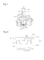
- Fig. 4 is a side view showing a structure of a main body portion of a ball seat of a stabilizer link of one embodiment according to the present invention.
- Fig. 5 is a perspective view showing a structure of the main body portion of the ball seat shown in Fig. 4 .
- Fig. 6 is a side cross sectional diagram showing a structure of the main body portion of the ball seat shown in Fig. 4 .
- Fig. 7 is a cross sectional diagram showing a structure of the main body portion of the ball seat shown in Fig. 4 .
- Fig. 8 is a perspective view showing a structure of a ball receiving portion of the main body portion shown in Fig. 4 .
- Fig. 9 is a perspective view showing a structure of a reinforcing portion of the main body portion shown in Fig. 4 .
- a stabilizer link 100 is equipped with a stud ball 101, a ball seat 200, a housing 300, a support bar 400, and a dust cover 500.
- the stud ball 101 is made of metal and is integrally formed. As shown in Fig. 3 , the stud ball 10 has a stud portion 110, a ball portion 120, a flange portion 130, a screw portion 140, a protruding portion 150, and a tapered portion 160.
- the stud portion 110 has a columnar shape.
- the ball portion 120 has a spherical shape and is formed at a lower end portion of the stud portion 110.
- the ball portion 120 has a center positioned on an axis O of the stud portion 110.
- the flange portion 130 and the protruding portion 150 are formed at an axis O direction middle portion of the stud portion 110.
- the screw portion 140 is formed at a leading end portion of the stud portion 110.
- the tapered portion 160 is formed between the protruding portion 150 and the ball portion 120.
- the ball seat 200 has a main body portion 201 and a fixing portion 202.
- the main body portion 201 has a ball receiving portion 210 and a reinforcing portion 220.
- the ball receiving portion 210 universally supports the ball portion 120 of the stud ball 101.
- the reinforcing portion 220 is formed at the outside of the ball receiving portion 210.
- the ball seat 200 is held in the housing 300 and is fixed at a bottom portion of the housing 300 by the fixing portion 202.
- the housing 300 has a flange portion 310 and a hole portion 320.
- the flange portion 310 is provided at an end portion of an opening side of the housing 300.
- the hole portion 320 is formed at a bottom portion of the housing 300.
- An end portion of the support bar 400 extending in a radial direction is fixed to an outer surface of a side surface portion of the housing 300.
- an end edge portion at a greater diameter side is held between the flange portion 211 of the ball seat 200 and the flange portion 310 of the housing 300, and an end edge portion at a smaller diameter side is fixed between the flange portion 130 of the stud ball 101 and the protruding portion 150.
- material of the ball receiving portion 210 of the main body portion 201 is selected from the following first materials
- material of the reinforcing portion 220 of the main body portion 201 is selected from the following second materials
- material of the fixing portion 202 is selected from the following second materials.
- the materials of the reinforcing portion 220 and the fixing portion 202 may be different from each other.
- the first materials are resins such as polyoxymethylene (POM), polypropylene (PP), polytetrafluoroethylene (PTFE), polybutylene terephthalate (PBT), polyether ether ketone (PEEK), nylon 66 (PA66), and the like.
- the second materials are reinforced resins and the like which are obtained by adding a reinforcing fiber (reinforcing agent) such as glass fiber (GF), carbon fiber (CF), or the like, to a resin such as polyoxymethylene (POM), polypropylene (PP), polytetrafluoroethylene (PTFE), polybutylene terephthalate (PBT), polyether ether ketone (PEEK), nylon 66 (PA66) or the like.
- a reinforcing fiber such as glass fiber (GF), carbon fiber (CF), or the like
- the second material is added to only a portion of the ball seat 200 (that is, the reinforcing portion 220 and the fixing portion 202), so that use amount of the second material, which is an expensive material, can be reduced.
- the added amount of glass fiber (GF), carbon fiber (CF), or the like is preferably set to be approximately 10 to 30 %.
- the production cost of the stabilizer link 100 can be reduced while the strength of the ball seat is maintained.
- nylon 66 (PA66) including 30 wt% of glass fiber (GF) is desirably used as the second material.
- PA66 nylon 66
- the stabilizer link using a ball portion of ⁇ 16 can obtain a pull-out strength of not less than 6000N.
- the ball receiving portion 210 of the main body portion 201 has a flange portion 211, a concave portion 212, and protruding portions 213.
- the ball receiving portion 210 is formed of polyoxymethylene (POM) which is an example of the first material.
- POM polyoxymethylene
- the flange portion 211, the concave portion 212, and the protruding portions 213 are integrally formed.
- the flange portion 211 is provided at an opening side of the ball receiving portion 210.
- the flange portion 211 protrudes toward the outside of the ball receiving portion 210.
- the inside of the concave portion 212 has a spherical shape corresponding to the shape of the outer surface of the ball portion 120.
- the outside of the concave portion 212 has a spherical shape which is similar to the inside shape of the concave portion 212.
- the concave portion 212 has a receiving portion 212a, an overhang portion 212b, and grease grooves 212c.
- the ball portion 120 of the ball stud 101 is slidably fitted to the concave portion 212.
- the receiving portion 212a is provided at the bottom side of the concave portion 212 from the center Z of the ball portion 120.
- the receiving portion 212a has a hemispherical shape corresponding to the shape of the side surface of the ball portion 120.
- the receiving portion 212a receives pressure when the ball stud 101 is pressed toward the bottom side of the ball seat 200.
- the overhang portion 212b is provided at the opening side of the concave portion 212 from the center Z of the ball portion 120.
- the overhang portion 212b has a shape corresponding to the shape of the side surface of the ball portion 120.
- the overhang portion 212b overhangs the ball portion 120. Therefore, when the pullout force is applied to the ball stud 100 and the overhang portion 212b thereby receives the pullout load, the overhang portion 212b withstands the pullout load, and removal of the ball portion 120 from the concave portion 212 can be prevented by the overhang portion 212b.
- the plural grease grooves 212c are formed so as to extend from the bottom side to the opening side of the concave portion 212, and are provided in the circumferential direction of the concave portion 212 at predetermined intervals.
- the number of the grease grooves 212c may be suitably selected and, for example, is eight.
- the grease grooves 212c are paths so that grease, which is filled in the insides of the concave portion 212 and the dust cover 500, can move in a space formed between the top and the bottom of the ball portion 120.
- the grease grooves 212c facilitate a heat cycle in which the grease absorbs heat and radiates the heat, and absorbs heat again.
- plural protruding portions 213 are provided at the outer circumferential wall at the opening side of the concave portion 212 at predetermined intervals.
- the protruding portion 213 is provided at the middle of the adjacent grease grooves 212c of the concave portion 212.
- the number of the grease grooves 212c may be suitably selected and, for example, is eight.
- the reinforcing portion 220 of the main body portion 201 has a fixing groove portion 221 and a holding portion 222.
- nylon 66 (PA66) including 30 wt% of glass fiber (GF) is used as the second material.
- the fixing groove portion 221 is formed at an outer surface of side surface of the holding portion 222 so as to extend in a circumferential direction.
- the fixing groove portion 221 has a recessed shape.
- the fixing groove portion 221 may be formed at the entire circumference of the outer surface of the side surface or may discretely be formed by providing a fixing groove portion 223 at a surface of the fixing groove portion 221 as shown in Fig. 12 .
- the number of the fixing groove portions 221 may be plural as long as a height direction space allows formation of the fixing groove portions 221.
- a fixing protrusion stripe portion 224 extending in a circumferential direction may be provided at the bottom portion side of the outer surface of the side surface portion of the holding portion 222.
- the holding portion 222 covers the outside of the concave portion 212 by closely adhering thereto.
- the holding portion 222 having higher strength than that of the concave portion 212 can be prevented from contacting the ball portion 120, so that deterioration of the surface roughness of the ball portion 120 can be prevented, and partial wear of the ball portion 120 can be prevented.
- damage of the ball portion 120 by the holding portion 222 can be prevented.
- the function of the stabilizer link 100 can be improved, so that the reliability of the stabilizer link 100 can be improved.
- the inside of the holding portion 222 has a spherical shape corresponding to that of the outside of the concave portion 212.
- the holding portion 222 can hold the concave portion 212.
- the function of the stabilizer link 100 can be improved, so that the reliability of the stabilizer link 100 can be improved.
- the holding portion 222 has an outside shape which is a cylindrical shape having a bottom, and is press-fitted into the inside of the housing 300.
- the holding portion 222 has a supporting portion 222a, a backup portion 222b, grease groove portions 222c, and slits 222d.
- the holding portion 222 holds the concave portion 212 of the ball receiving portion 210.
- the supporting portion 222a is provided at the bottom side of the holding portion 222 from the center Z of the ball portion 120.
- the supporting portion 222a has a shape corresponding to the outside shape of the concave portion 212.
- the supporting portion 222a supports the receiving portion 212a of the ball receiving portion 210.
- the backup portion 222b is provided at the opening side of the holding portion 222 from the center Z of the ball portion 120.
- the backup portion 222b overhangs the overhang portion 212b.
- the backup portion 222b reinforces the overhang portion 212b which directly receives the pullout load of the backup portion 222b.
- the backup portion 222b withstands the pullout load, and removal of the ball portion 120 from the concave portion 212 can be prevented by the backup portion 222b. As a result, breakage of the stabilizer link 100 can be prevented, so that the reliability of the stabilizer link 100 can be improved.
- the backup portion 222b reinforces the overhang portion 212b, and the flange portion 211 and the concave portion 212 are integrally formed. Therefore, even when the concave portion 212 receives the pullout load, damage of the concave portion 212 can be prevented, and removal of the dust cover 500 can be prevented. When the concave portion 212 receives the pullout load, the removal of concave portion 212 from the holding portion 222 can be prevented even if the concave portion 212 is separated at the boundary between the ball receiving portion 210 and the reinforcing portion 220.
- plural convex portions 222e are formed at the backup portion 222b by providing plural slits 222d.
- the convex portions 222e of the backup portion 222b are pressed toward the outside, and the opening portion of the ball seat 200 can open widely.
- the ball portion 120 can be pressed into the concave portion 212, and the core can be removed from the concave portion 212.
- the backup portion 222b withstands the pullout load, and removal of the ball portion 120 from the concave portion 212 can be prevented by the backup portion 222b even when the plural convex portions 222e are formed. Specifically, when the ball portion 120 of the stud ball 101 1 is fitted into the concave portion 212 of the ball seat 200 and then the ball seat 200 is provided in the housing 300, increase in outer diameter of the backup portion 222b is prevented by the housing 300, so that expansion of the opening portion of the ball seat 200 can be inhibited, and the backup portion 222b withstands the pullout load, and removal of the ball portion 120 from the concave portion 212 can be prevented by the backup portion 222b.
- the convex portion 222e is provided such that the grease groove portion 222c is positioned at the center of the convex portion 222e.
- the width W of the convex portion 222e is set such that the convex portion 222e uniformly extends toward both sides around the grease groove portion 222c.
- the height H of the convex portion 222e is a height from the center Z of the ball portion 120 to the opening portion. As long as the stiffness of the convex portion 222e can be secured and the ball portion 120 can be fitted into the concave portion 212, the height H of the convex portion 222e may be suitably changed.
- the number of the convex portions 222e is set to be the same as that of the grease groove portions 222c, and is, for example, eight.
- the height H and the width W of the convex portion 222e are set so as to satisfy the following first formula. 1.0 ⁇ height H of the convex portion / width W of the convex portion ⁇ 2.0
- the height H of the convex portion 222e is set to be about 7 mm, and the width W of the convex portion 222e is set to be about 4 mm.
- the height H and the width W of the convex portion 222e are set so as to satisfy the first formula, so that the elasticity of the backup portion 222b can be maintained, and the strength of the backup portion 222b can be improved.
- the protruding portions 213 of the ball receiving portion 210 are fitted to the slits 222d of the reinforcing portion 220.
- the concave portion 212 engages with the holding portion 222, thereby preventing rotating of the concave portion 212.
- An exposed portion of the ball receiving portion 210 is provided at the outer circumference of the ball seat 200, and a fit margin between the housing 300 and the ball seat 200 is set, so that the torque of the stabilizer link 100 can be adjusted such that the ball portion 120 can slide.
- the grease groove portions 222c are disposed so as to overlap the grease grooves 212c of the concave portion 212 at the inside of the holding portion 222, and extend from the bottom side to the opening side of the holding portion 222.
- the number of the grease groove portions 222c is eight.
- the grease groove portions 222c are paths so that grease, which is filled at the inside of the concave portion 212 and the dust cover 500, moves in the space formed between the top and the bottom of the ball portion 120.
- the grease groove portions 222c facilitate a heat cycle in which the grease absorbs heat and radiates the heat, and absorbs heat again.
- the grease grooves 212c and the grease groove portions 222c are grease flow passageways for circulating the grease.
- the grease grooves 212c are provided to the concave portion 212, and the concave portion 212 is not covered with the holding portion 222. Therefore, the grease groove portions 222c are provided to the holding portion 222, so that contact between the ball portion 120 and the holding portion 222 is prevented.
- the fixing portion 202 is formed so as to cover the bottom portion side of the outer surface of the side surface portion of the holding portion 222.
- a fixing protrusion stripe portion 231 which is fitted to the fixing groove portion 221 of the reinforcing portion 220, is formed at the fixing portion 202.
- the fixing protrusion stripe portion 231 and the fixing groove portion 221 form a fitting portion and can mechanically engage with each other.
- a projection portion 232 projecting from the hole portion 320 of the housing 300 to an external portion is formed at a bottom portion of the fixing portion 202.
- a leading end portion of the projection portion 232 has a shape to engage with an outer surface of the bottom portion of the housing 300, and has, for example, a bottom shape.
- the projection portion 232 can prevent removal of the fixing portion 202 from the housing 300.
- the fitting portion (the fixing groove portion 221 and the fixing protrusion stripe portion 231) and the projection portion 232
- the fitting portion and the projection portion 232 withstand the pullout load, and thereby removal of the ball seat 200 from the housing 300 can be effectively prevented.
- breakage of the stabilizer link 100 can be prevented, so that the reliability of the stabilizer link 100 can be improved.
- the shape and the number of the fixing protrusion stripe portion 231 correspond to those of the fixing groove portion 221 of the reinforcing portion 220.
- a fixing groove portion having a shape corresponding to that of the fixing protrusion stripe portion 224 is formed at the fixing portion 202.
- the projection portion 232 is provided at a position spaced from the center of the bottom portion of the housing 300, so that rotation of the ball seat 200 relative to the housing 300 can be prevented.
- the cross sectional shape of the pole portion of the projection portion is asymmetric with respect to the center thereof, so that rotation of the ball seat 200 relative to the housing 300 can be prevented.
- the number of the projection portions 232 can be suitably selected, and is, for example, two. In this case, rotation of the ball seat 200 relative to the housing 300 can be effectively prevented.
- the value obtained by multiplying total cross sectional area of the pole portions of the projection portions formed in the hole portions 320 by tensile breakage strength is desirably set to be not less than 2kN when a ball portion of ⁇ 16 is used as the ball portion of the stud ball.
- the above total cross sectional area of the pole portions is the value obtained by (the number of the pole portions) x(cross sectional area of the one pole portion).
- the pull-out strength can be about two times as that in a case in which polyoxymethylene (POM) is used as the material of the ball seat 3 of the conventional stabilizer link 1 shown in Fig. 2 and cross sectional area of the pole portion is equal to that in the above case of this embodiment.
- POM polyoxymethylene
- a subassembly 100A which has the stud ball 101, the main body portion 201 of the ball seat 200, the housing 300, the support bar 400 and the dust cover 500, is formed.
- a space S is formed between the bottom portion side of the outer surface of the side surface portion of the holding portion 222 of the main body portion 201 and the bottom portion side of the inner surface of the housing 300.
- the subassembly 100A has the same structure as that shown in Fig. 3 other than not forming of the fixing portion 202 of the ball seat 200.
- the main body portion 201 of the ball seat 200 is obtained by a method proposed by the inventor in Patent Document 1.
- the fixing groove portion 221 is formed at the outer surface of the side surface portion of the reinforcing portion 220.
- the number of the hole portions 320 is set to be two, and the positions thereof are set to be symmetric with respect to the center of the bottom portion of the housing 300.
- an injection molding die 600 (hereinafter simply referred to as "die 600") is provided to the outer surface of the bottom portion side of the housing 300 in the subassembly 100A, and a cavity C is thereby formed.
- the bottom portion of the housing 300 is disposed so as to be directed to the upper side.
- the die 600 has hole portions 600A positioned so as to face the hole portions 320 of the housing 300, and wide width portions 600B, which have a shape corresponding to that of the projection portions 232 of the fixing portion 202, are formed at end portion sides of the hole portions 600A proximate to the housing.
- a resin injection gate 601 is inserted into one of the hole portions 600A of the die 600, and a gas discharge member 602 is inserted into another of the hole portions 600A of the die 600.
- a reinforced resin R is injected from a hole portion of the resin injection gate 601, and a gas G is discharged from a hole portion of the resin injection gate 601.
- a gap 603 is provided between an inner peripheral surface of the hole portion 600A and an outer peripheral surface of a sleeve of the resin injection gate 601, and a gap 603 is provided between an inner peripheral surface of the hole portion 600A and an outer peripheral surface of a sleeve of the gas discharge member 602.
- the gaps 603 are gas discharge clearances.
- the gap 603 in the hole portion 600A at the side of the gas discharge member 602 has a clearance which is set to be larger than that of the gap 603 in the hole portion 600A at the side of the resin injection gate 601.
- the resin injection gate 601 may be inserted to both of the hole portions 600A.
- the clearance of each gaps 603 is shown to be large.
- the shape of the hole portion 320 corresponding to that of the pole portion of the projection portion 232 is not limited as long as resin injection and gas discharge can be performed.
- this shape may be a column shape or a rectangular column shape, and the cross sectional shape thereof is not limited.
- injection molding is performed such that the reinforced resin R which is the second material is injected into the cavity C and the space S.
- the reinforced resin R is injected from the hole portion of the resin injection gate 601.
- the gas G is discharged from the hole portion of the gas discharge member 602 and the gaps 603.
- the fixing portion 202 is formed at the bottom portion side of the side surface portion of the holding portion 222 of the main body portion 201.
- the reinforced resin R is flowed to the outer surface of the side surface portion of the holding portion 222, so that the fixing protrusion stripe portion 231, which is fitted to the fixing groove portion 221 of the holding portion 222, is formed at the fixing portion 202, and the projection portion 232, which projects from the hole portion 320 of the housing 300 to an external portion, is formed at the bottom portion of the fixing portion 202, and the projection portion 232 is formed to have a shape engaging with the outer surface of the bottom portion of the housing 300.
- the stabilizer link 100 shown in Fig. 3 is produced.
- the reinforced resin R is flowed to the outer surface of the side surface portion of the main body portion 201 via the hole portion 320 of the housing 300, and the fixing protrusion stripe portion 231 (second fit shape) fitted to the fixing groove portion 221 (first fit shape) is formed at the fixing portion 202.
- the main body portion 201 and the fixing portion 202 can mechanically engage with each other by the fitting portion formed by the fixing groove portion 221 and the fixing protrusion stripe portion 231. Therefore, in the ball seat 200, removal of the main body portion 201 from the fixing portion 202 can be prevented without chemical combination of the respective resins which are the materials of the main body portion 201 and the fixing portion 202.
- the projection portion 232 of the fixing portion 202 is formed to have a shape engaging with the outer surface of the bottom portion of the housing 300, so that removal of the fixing portion 202 from the housing 300 can be prevented.
- the reinforced resin R including the reinforcing agent is injected by the injection molding, so that normal array of the reinforcing agent (reinforcing fiber or the like) can easily be obtained differently from the conventional caulking methods (thermal caulking, ultrasonic caulking, and the like).
- the fixing portion 202 can obtain the inherent strength of the reinforced resin, so that desired pull-out strength of the stud ball 101 can be obtained.
- chemical combination of the respective resins of the main body portion 201 and the fixing portion 202 is unnecessary, and consideration of the combination compatibility between the resins is unnecessary, so that selection of the resins used in the injection molding can be wider.
- the outer surfaces of the bottom portions of the projection portions 232 of the fixing portion 202 and the housing 300 can strongly contact each other by molding shrinkage of the injected reinforced resin, so that characteristics of sealing from muddy water or the like from an external portion can be improved.
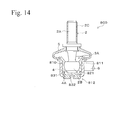
- Fig. 14 is a side cross sectional diagram showing a modification example of a stabilizer link of one embodiment according to the present invention.
- a stabilizer link 800 has the same structure as that of the stabilizer link 100 shown in Fig. 2 other than the ball seat.
- a ball seat 800 has a main body portion 811 and a fixing portion 812.
- a material of the main body portion 811 is selected from the group of the first materials
- a material of the fixing portion 812 is selected from the group of the second materials.
- a fixing groove portion 821 which has the same shape as that of the fixing groove portion 221 of the above embodiment, is formed at a bottom portion side of outer surface of side surface portion of the main body portion 811.
- a fixing protrusion stripe portion 831 which is fitted to the fixing groove portion 821 of the main body portion 811, is formed at the fixing portion 812.
- a projection portion 832 projecting from the hole portion 4A of the housing 4 to an external portion is formed at a bottom portion of the fixing portion 812.
- the projection portion 832 has the same shape as that of the projection portion 232 of the above embodiment.
- the fixing portion 812 can yield the same actions and effects as those of the fixing portion 202 of the above embodiment.
Landscapes
- Engineering & Computer Science (AREA)
- Mechanical Engineering (AREA)
- General Engineering & Computer Science (AREA)
- Manufacturing & Machinery (AREA)
- Physics & Mathematics (AREA)
- Geometry (AREA)
- Vehicle Body Suspensions (AREA)
- Pivots And Pivotal Connections (AREA)
Abstract
Description
- The present invention relates to a stabilizer link equipped with a ball seat. In particular, the present invention relates to an improvement in a method of fixing the ball seat.
- A stabilizer link is a stabilizer link part connecting a suspension apparatus and a stabilizer apparatus.
Fig. 1 is a perspective view showing a schematic structure of front wheel side of vehicle. Eachsuspension apparatus 10 is provided at left andright tires 30 and has anarm 11 and acylinder 12. A lower end portion of thearm 11 is fixed at a bearing portion which supports a shaft of thetire 30. Thecylinder 12 is elastically movable relatively to thearm 11. Abracket 13, to which astabilizer link 1 is mounted, is provided at the arm 11: Thesuspension apparatus 10 supports the weight of vehicle body which is applied to thetire 30. Astabilizer apparatus 20 is equipped with abar 21 which is approximately U-shaped, and thestabilizer apparatus 20 is mounted to the vehicle body viabushes 22. Thestabilizer apparatus 20 secures roll stiffness of vehicle. - The
stabilizer links 1 are provided at thebracket 13 of thesuspension apparatus 10 and at the end portion of thebar 21 of thestabilizer apparatus 20. Thestabilizer links 1 are connected to each other by asupport bar 6. Thestabilizer link 1 transmits a load, which is generated when thesuspension apparatus 10 receives an input from a road surface, to thestabilizer apparatus 20. -
Fig. 2 is a side sectional diagram showing a specific example of structure of thestabilizer link 1. Thestabilizer link 1 is equipped with astud ball 2, aball seat 3, ahousing 4, and adust cover 5. - The
stud ball 2 has astud portion 2A and aball portion 2B which are integrally formed. Ascrew portion 2C is formed at a leading end portion of thestud portion 2A. Thescrew portion 2C of thestabilizer link 1 proximate to thesuspension apparatus 10 is fixed at thebracket 13 of thearm 11 by screw fastening, and thescrew portion 2C of thestabilizer link 1 proximate to thestabilizer apparatus 20 is fixed at thebar 21 by screw fastening. Theball seat 3 and thehousing 4 form a pivot support member which universally supports thestud ball 2. - The
ball portion 2B of thestud ball 2 is press-fitted into aconcave portion 3A of theball seat 3, and theconcave portion 3A of the ball seat has a bearing function. Thehousing 4 holds theball seat 3 therein. Thedust cover 5 prevents foreign objects from entering theconcave portion 3A of theball seat 3. Thesupport bar 6, which connects thestabilizer links 1, is provided at a side surface of thehousing 4. Athermal caulking portion 3B, which is used as a fixing portion, is formed at a bottom portion of theball seat 3. In formation of thethermal caulking portion 3B, a pin portion of theball seat 3 is projected from ahole portion 4A of thehousing 4 to an external portion, and the pin portion is deformed by thermal caulking or ultrasonic caulking, so that the deformed pin portion is caulked to the outside of thehousing 4. Theball seat 3 is fixed to thehousing 4 by thethermal caulking portion 3B (for example,Patent Documents 1 and 2). - In this
stabilizer link 1, in order to prevent removal ofball portion 2B of thestud ball 2 from theconcave portion 3A of theball seat 3, it is necessary that pull-out strength be increased. In this case, the strength of thethermal caulking portion 3B, which is a portion for fixing theball seat 3 to thehousing 4, corresponds to the strength of theball seat 3 made of the same material, so that pull-out strength of thestud ball 2 is determined by the strength of theball seat 3. - It is thought that a reinforced resin including a reinforcing agent (glass fiber or the like) is used for the
ball seat 3 in order to increase the strength of theball seat 3. However, in this case, the reinforcing agent may have characteristics of attack to theball portion 2B of thestud ball 2, so that the bearing function of theball seat 3 may be deteriorated. On the other hand, when polyoxymethylene (POM), which does not include a reinforcing agent, is used as a material of theball seat 3 in order to prioritize the bearing function, for example, only the pull-out strength of about 2000N to 2800N may be obtained in use of a ball portion of ϕ 16. - The inventor has proposed a hybrid type ball seat obtained by two-color molding in order to realize both increase in pull-out strength and prevention of bearing function deterioration (for example, Patent Document 3). The hybrid type ball seat has a ball receiving portion and a reinforcing portion. The ball receiving portion has a bearing function for universally supporting a ball portion of a stud ball. The reinforcing portion is formed at the outside of the ball receiving portion and made of a reinforced resin.
-
Patent Document 1 is Japanese Unexamined Patent Application Publication No.Hei 6-117429 Patent Document 2 is Japanese Unexamined Patent Application Publication No.Hei 7-54835 Patent Document 3 is Japanese Unexamined Patent Application Publication No.2010-65725 - However, in the hybrid type ball seat, in a case in which the ball seat is fixed by the
thermal caulking portion 3B in the same manner as in the ball seat of thestabilizer link 1, it may be difficult to control the action of the reinforcing agent included in the reinforced resin when thermal caulking or ultrasonic caulking is performed. Due to this, breakage of normal array of reinforcing fiber may easily occur, so that desired pull-out strength cannot be obtained. - Therefore, an object of the present invention is to provide a stabilizer link and a production method therefor which can obtain desired pull-out strength even when a reinforced resin is used for a fixing portion of a ball seat.
- According to one aspect of the present invention, a production method for a stabilizer link includes: a subassembly forming step in which a subassembly having a stud ball, a main body of a ball seat, and a housing is formed, wherein in the subassembly forming step, a space is formed between a bottom side of a side surface of the main body and a bottom side of an inner surface of the housing; a cavity forming step in which a die is provided to an outer surface of a bottom side of the housing in the subassembly and a cavity is thereby formed; and an injection molding step in which injection molding is performed such that a reinforced resin is injected into the cavity and the space, and a fixing portion of the ball seat is thereby formed so as to cover the bottom side of the side surface of the main body, wherein in formation of the main body of the ball seat, a first fit shape including at least one of a recess and a protrusion is formed at the bottom side of the side surface of the main body, and in formation of the fixing portion of the ball seat, a resin including a reinforcing agent is used as the reinforced resin, the reinforced resin is flowed to an outer surface of the side surface of the main body through a hole of the housing, so that a second fit shape fitted to the first fit shape is formed at the fixing portion, a projection projecting from the hole of the housing to an external is formed at a bottom of the fixing portion, and the projection is formed to have a shape engaging with the outer surface of the bottom of the housing.
- In the production method for stabilizer link according to the above aspect of the present invention, the subassembly is formed such that the space is formed between the bottom side of the side surface of the main body and the bottom side of the inner surface of the housing. The die is provided to the outer surface of the bottom side of the housing in the subassembly, and the cavity is thereby formed. The injection molding is performed such that the reinforced resin is injected into the cavity and the space, and the fixing portion is thereby formed at the ball seat so as to cover the bottom side of the side surface of the main body.
- In the formation of the fixing portion of the ball seat, the reinforced resin is flowed to the outer surface of the side surface of the main body via the hole of the housing, the second fit shape fitted to the first fit shape of the main body is formed at the fixing portion. Thus, the main body and the fixing portion can mechanically engage with each other by the fitting portion formed by the first fit shape (main body side fit shape) and the second fit shape (fixing portion side fit shape). Therefore, in the ball seat, removal of the main body from the fixing portion can be prevented without chemical combination of the respective resins which are the materials of the main body and the fixing portion. The projection of the fixing portion is formed to have the shape engaging with the outer surface of the bottom of the housing, so that removal of the fixing portion from the housing can be prevented.
- In the production method for stabilizer link according to the above aspect of the present invention, the reinforced resin including the reinforcing agent is injected in the injection molding, so that normal array of the reinforcing agent (reinforcing fiber or the like) can easily be obtained differently from the conventional caulking methods (thermal caulking, ultrasonic caulking, and the like). Thus, the fixing portion can obtain the inherent strength of the reinforced resin, so that desired pull-out strength of the stud ball can be obtained. In this case, in the fixture of the fixing portion to the main body, as described above, chemical combination of the respective resins of the main body and the fixing portion is unnecessary, and consideration of the combination compatibility between the resins is unnecessary, so that selection of the resins used in the injection molding can be wider. The outer surfaces of the bottoms of the projection of the fixing portion and the housing can strongly contact each other by molding shrinkage of the injected reinforced resin, so that characteristics of sealing from muddy water or the like from an external can be improved.
- The production method for stabilizer link according to the above aspect of the present invention can use various structures. For example, according to one desirable embodiment of the present invention, a feature can be used in which another hole is formed at the bottom of the housing, and in the formation of the fixing portion of the ball seat, in injection of the reinforced resin into the cavity and the space, a gas is discharged from the another hole, another projection projecting from the another hole to an external is formed, and the another projection is formed to have a shape engaging with the outer surface of the bottom of the housing. In this feature, rotation of the ball seat relative to the housing about an axis can be effectively prevented.
- According to another aspect of the present invention, a stabilizer link is produced by the production method for stabilizer link according to the above aspect of the present invention. That is, a stabilizer link includes: a stud ball having a ball; a ball seat having a main body and a fixing portion, the ball is slidably fitted into the main body, the fixing portion formed so as to cover a bottom side of a side surface of the main body; and a housing holding the ball seat therein and having a hole at a bottom thereof, wherein the fixing portion is made of a reinforced resin including a reinforcing agent, a first fit shape including at least one of a recess and a protrusion is formed at the bottom side of the side surface of the main body, and a second fit shape fitted to the first fit shape is formed at the fixing portion, and a projection projecting from the hole of the housing to an outside is formed at a bottom of the fixing portion, and the projection is formed to have a shape engaging with an outer surface of the bottom of the housing. The stabilizer link of the above aspect of the present invention can obtain the same effects as those of the production method for stabilizer link according to the above aspect of the present invention.
- The stabilizer link of the above aspect of the present invention can use various structures. For example, according to one desirable embodiment of the present invention, a feature can be used in which the main body of the ball seat has a ball receiving portion and a reinforcing portion, the ball is slidably fitted into ball receiving portion, the reinforcing portion formed at an outside of the ball receiving portion and made of a reinforced resin, the first fit shape is formed at a bottom side of a side surface of the reinforcing portion, and the fixing portion is formed so as to cover the bottom side of the side surface of the reinforcing portion.
- According to the stabilizer link or the production method therefor, the desired pull-out strength can be obtained even when the reinforced resin is used for the fixing portion of the ball seat, and another effect can be obtained.
-
-
Fig. 1 is a perspective view showing a schematic structure of a front wheel side of vehicle. -
Fig. 2 is a side cross sectional diagram showing a structure of a conventional stabilizer link. -
Fig. 3 is a side cross sectional diagram showing a structure of a stabilizer link of one embodiment according to the present invention. -
Fig. 4 is a side view showing a structure of a main body portion of a ball seat of a stabilizer link of one embodiment according to the present invention. -
Fig. 5 is a perspective view showing a structure of the main body portion of the ball seat shown inFig. 4 . -
Fig. 6 is a side cross sectional diagram showing a structure of the main body portion of the ball seat shown inFig. 4 . -
Fig. 7 is a cross sectional diagram showing a structure of the main body portion of the ball seat shown inFig. 4 . -
Fig. 8 is a perspective view showing a structure of a ball receiving portion of the main body portion shown inFig. 4 . -
Fig. 9 is a perspective view showing a structure of a reinforcing portion of the main body portion shown inFig. 4 . -
Figs. 10A and 10B are diagrams for explaining injection molding of a production method for stabilizer links according to one embodiment of the present invention.Fig. 10A is a side cross sectional diagram showing a condition of injection molding.Fig. 10B is a plan view showing a lower surface of a bottom portion of a housing. -
Fig. 11 is a side cross sectional diagram showing a modification example of a die used in the injection molding shown inFigs. 10A and 10B . -
Fig. 12 is a side view showing a structure of a modification example of a main body portion of a ball seat of a stabilizer link of one embodiment according to the present invention. -
Fig. 13 is a side view showing a structure of another modification example of a main body portion of a ball seat of a stabilizer link of one embodiment according to the present invention. -
Fig. 14 is a side cross sectional diagram showing a modification example of a stabilizer link of one embodiment according to the present invention. -
Reference numeral - An embodiment of the present invention will be explained hereinafter with reference to Figures.
Fig. 3 is a side cross sectional diagram showing a structure of a stabilizer link of an embodiment according to the present invention.Fig. 4 is a side view showing a structure of a main body portion of a ball seat of a stabilizer link of one embodiment according to the present invention.Fig. 5 is a perspective view showing a structure of the main body portion of the ball seat shown inFig. 4 .Fig. 6 is a side cross sectional diagram showing a structure of the main body portion of the ball seat shown inFig. 4 .Fig. 7 is a cross sectional diagram showing a structure of the main body portion of the ball seat shown inFig. 4 .Fig. 8 is a perspective view showing a structure of a ball receiving portion of the main body portion shown inFig. 4 .Fig. 9 is a perspective view showing a structure of a reinforcing portion of the main body portion shown inFig. 4 . - As shown in
Fig. 3 , astabilizer link 100 is equipped with astud ball 101, aball seat 200, ahousing 300, asupport bar 400, and adust cover 500. - The
stud ball 101 is made of metal and is integrally formed. As shown inFig. 3 , thestud ball 10 has astud portion 110, aball portion 120, aflange portion 130, ascrew portion 140, a protrudingportion 150, and atapered portion 160. For example, thestud portion 110 has a columnar shape. Theball portion 120 has a spherical shape and is formed at a lower end portion of thestud portion 110. Theball portion 120 has a center positioned on an axis O of thestud portion 110. Theflange portion 130 and the protrudingportion 150 are formed at an axis O direction middle portion of thestud portion 110. Thescrew portion 140 is formed at a leading end portion of thestud portion 110. The taperedportion 160 is formed between the protrudingportion 150 and theball portion 120. - The
ball seat 200 has amain body portion 201 and a fixingportion 202. Themain body portion 201 has aball receiving portion 210 and a reinforcingportion 220. Theball receiving portion 210 universally supports theball portion 120 of thestud ball 101. The reinforcingportion 220 is formed at the outside of theball receiving portion 210. Theball seat 200 is held in thehousing 300 and is fixed at a bottom portion of thehousing 300 by the fixingportion 202. - The
housing 300 has aflange portion 310 and ahole portion 320. Theflange portion 310 is provided at an end portion of an opening side of thehousing 300. Thehole portion 320 is formed at a bottom portion of thehousing 300. An end portion of thesupport bar 400 extending in a radial direction is fixed to an outer surface of a side surface portion of thehousing 300. In thedust cover 500, an end edge portion at a greater diameter side is held between theflange portion 211 of theball seat 200 and theflange portion 310 of thehousing 300, and an end edge portion at a smaller diameter side is fixed between theflange portion 130 of thestud ball 101 and the protrudingportion 150. - In the
ball seat 200, for example, material of theball receiving portion 210 of themain body portion 201 is selected from the following first materials, for example, material of the reinforcingportion 220 of themain body portion 201 is selected from the following second materials, and, for example, material of the fixingportion 202 is selected from the following second materials. In this case, the materials of the reinforcingportion 220 and the fixingportion 202 may be different from each other. - The first materials are resins such as polyoxymethylene (POM), polypropylene (PP), polytetrafluoroethylene (PTFE), polybutylene terephthalate (PBT), polyether ether ketone (PEEK), nylon 66 (PA66), and the like. The second materials are reinforced resins and the like which are obtained by adding a reinforcing fiber (reinforcing agent) such as glass fiber (GF), carbon fiber (CF), or the like, to a resin such as polyoxymethylene (POM), polypropylene (PP), polytetrafluoroethylene (PTFE), polybutylene terephthalate (PBT), polyether ether ketone (PEEK), nylon 66 (PA66) or the like.
- The second material is added to only a portion of the ball seat 200 (that is, the reinforcing
portion 220 and the fixing portion 202), so that use amount of the second material, which is an expensive material, can be reduced. Thus, production cost can be reduced. The added amount of glass fiber (GF), carbon fiber (CF), or the like, is preferably set to be approximately 10 to 30 %. By using such an amount of glass fiber (GF), carbon fiber (CF), or the like, the production cost of thestabilizer link 100 can be reduced while the strength of the ball seat is maintained. For example, nylon 66 (PA66) including 30 wt% of glass fiber (GF) is desirably used as the second material. In this case, for example, the stabilizer link using a ball portion of ϕ 16 can obtain a pull-out strength of not less than 6000N. - For example, as shown in
Fig. 8 , theball receiving portion 210 of themain body portion 201 has aflange portion 211, aconcave portion 212, and protrudingportions 213. Theball receiving portion 210 is formed of polyoxymethylene (POM) which is an example of the first material. Theflange portion 211, theconcave portion 212, and the protrudingportions 213 are integrally formed. - For example, the
flange portion 211 is provided at an opening side of theball receiving portion 210. Theflange portion 211 protrudes toward the outside of theball receiving portion 210. The inside of theconcave portion 212 has a spherical shape corresponding to the shape of the outer surface of theball portion 120. The outside of theconcave portion 212 has a spherical shape which is similar to the inside shape of theconcave portion 212. Theconcave portion 212 has a receivingportion 212a, anoverhang portion 212b, andgrease grooves 212c. Theball portion 120 of theball stud 101 is slidably fitted to theconcave portion 212. - For example, the receiving
portion 212a is provided at the bottom side of theconcave portion 212 from the center Z of theball portion 120. The receivingportion 212a has a hemispherical shape corresponding to the shape of the side surface of theball portion 120. The receivingportion 212a receives pressure when theball stud 101 is pressed toward the bottom side of theball seat 200. - For example, the
overhang portion 212b is provided at the opening side of theconcave portion 212 from the center Z of theball portion 120. Theoverhang portion 212b has a shape corresponding to the shape of the side surface of theball portion 120. Theoverhang portion 212b overhangs theball portion 120. Therefore, when the pullout force is applied to theball stud 100 and theoverhang portion 212b thereby receives the pullout load, theoverhang portion 212b withstands the pullout load, and removal of theball portion 120 from theconcave portion 212 can be prevented by theoverhang portion 212b. - For example, the
plural grease grooves 212c are formed so as to extend from the bottom side to the opening side of theconcave portion 212, and are provided in the circumferential direction of theconcave portion 212 at predetermined intervals. The number of thegrease grooves 212c may be suitably selected and, for example, is eight. Thegrease grooves 212c are paths so that grease, which is filled in the insides of theconcave portion 212 and thedust cover 500, can move in a space formed between the top and the bottom of theball portion 120. Thegrease grooves 212c facilitate a heat cycle in which the grease absorbs heat and radiates the heat, and absorbs heat again. - For example, plural protruding
portions 213 are provided at the outer circumferential wall at the opening side of theconcave portion 212 at predetermined intervals. The protrudingportion 213 is provided at the middle of theadjacent grease grooves 212c of theconcave portion 212. The number of thegrease grooves 212c may be suitably selected and, for example, is eight. - For example, as shown in
Fig. 9 , the reinforcingportion 220 of themain body portion 201 has a fixinggroove portion 221 and a holdingportion 222. In the reinforcingportion 220, for example, nylon 66 (PA66) including 30 wt% of glass fiber (GF) is used as the second material. - The fixing
groove portion 221 is formed at an outer surface of side surface of the holdingportion 222 so as to extend in a circumferential direction. The fixinggroove portion 221 has a recessed shape. The fixinggroove portion 221 may be formed at the entire circumference of the outer surface of the side surface or may discretely be formed by providing a fixinggroove portion 223 at a surface of the fixinggroove portion 221 as shown inFig. 12 . The number of the fixinggroove portions 221 may be plural as long as a height direction space allows formation of the fixinggroove portions 221. As shown inFig. 13 , instead of the fixinggroove portion 221, a fixingprotrusion stripe portion 224 extending in a circumferential direction may be provided at the bottom portion side of the outer surface of the side surface portion of the holdingportion 222. - For example, the holding
portion 222 covers the outside of theconcave portion 212 by closely adhering thereto. Thus, the holdingportion 222 having higher strength than that of theconcave portion 212 can be prevented from contacting theball portion 120, so that deterioration of the surface roughness of theball portion 120 can be prevented, and partial wear of theball portion 120 can be prevented. Thus, damage of theball portion 120 by the holdingportion 222 can be prevented. As a result, the function of thestabilizer link 100 can be improved, so that the reliability of thestabilizer link 100 can be improved. - The inside of the holding
portion 222 has a spherical shape corresponding to that of the outside of theconcave portion 212. When theconcave portion 212 of theball receiving portion 210 receives the pullout load, the holdingportion 222 can hold theconcave portion 212. As a result, the function of thestabilizer link 100 can be improved, so that the reliability of thestabilizer link 100 can be improved. - For example, the holding
portion 222 has an outside shape which is a cylindrical shape having a bottom, and is press-fitted into the inside of thehousing 300. The holdingportion 222 has a supportingportion 222a, abackup portion 222b,grease groove portions 222c, and slits 222d. The holdingportion 222 holds theconcave portion 212 of theball receiving portion 210. - The supporting
portion 222a is provided at the bottom side of the holdingportion 222 from the center Z of theball portion 120. The supportingportion 222a has a shape corresponding to the outside shape of theconcave portion 212. The supportingportion 222a supports the receivingportion 212a of theball receiving portion 210. - The
backup portion 222b is provided at the opening side of the holdingportion 222 from the center Z of theball portion 120. Thebackup portion 222b overhangs theoverhang portion 212b. Thebackup portion 222b reinforces theoverhang portion 212b which directly receives the pullout load of thebackup portion 222b. When theoverhang portion 212b of theconcave portion 222 receives the pullout load, thebackup portion 222b withstands the pullout load, and removal of theball portion 120 from theconcave portion 212 can be prevented by thebackup portion 222b. As a result, breakage of thestabilizer link 100 can be prevented, so that the reliability of thestabilizer link 100 can be improved. - The
backup portion 222b reinforces theoverhang portion 212b, and theflange portion 211 and theconcave portion 212 are integrally formed. Therefore, even when theconcave portion 212 receives the pullout load, damage of theconcave portion 212 can be prevented, and removal of thedust cover 500 can be prevented. When theconcave portion 212 receives the pullout load, the removal ofconcave portion 212 from the holdingportion 222 can be prevented even if theconcave portion 212 is separated at the boundary between theball receiving portion 210 and the reinforcingportion 220. - For example, plural
convex portions 222e are formed at thebackup portion 222b by providingplural slits 222d. In a case in which theball portion 120 of thestud ball 101 is pressed into theconcave portion 212 of theball seat 200, in a case in which a core is provided in theconcave portion 212 of theball receiving portion 210 and is removed therefrom after molding of theball seat 200 having theball receiving portion 210 and the holdingportion 222, and the like, theconvex portions 222e of thebackup portion 222b are pressed toward the outside, and the opening portion of theball seat 200 can open widely. Thus, theball portion 120 can be pressed into theconcave portion 212, and the core can be removed from theconcave portion 212. - The
backup portion 222b withstands the pullout load, and removal of theball portion 120 from theconcave portion 212 can be prevented by thebackup portion 222b even when the pluralconvex portions 222e are formed. Specifically, when theball portion 120 of thestud ball 101 1 is fitted into theconcave portion 212 of theball seat 200 and then theball seat 200 is provided in thehousing 300, increase in outer diameter of thebackup portion 222b is prevented by thehousing 300, so that expansion of the opening portion of theball seat 200 can be inhibited, and thebackup portion 222b withstands the pullout load, and removal of theball portion 120 from theconcave portion 212 can be prevented by thebackup portion 222b. - For example, the
convex portion 222e is provided such that thegrease groove portion 222c is positioned at the center of theconvex portion 222e. The width W of theconvex portion 222e is set such that theconvex portion 222e uniformly extends toward both sides around thegrease groove portion 222c. The height H of theconvex portion 222e is a height from the center Z of theball portion 120 to the opening portion. As long as the stiffness of theconvex portion 222e can be secured and theball portion 120 can be fitted into theconcave portion 212, the height H of theconvex portion 222e may be suitably changed. The number of theconvex portions 222e is set to be the same as that of thegrease groove portions 222c, and is, for example, eight. - The height H and the width W of the
convex portion 222e are set so as to satisfy the following first formula.
- For example, the height H of the
convex portion 222e is set to be about 7 mm, and the width W of theconvex portion 222e is set to be about 4 mm. The height H and the width W of theconvex portion 222e are set so as to satisfy the first formula, so that the elasticity of thebackup portion 222b can be maintained, and the strength of thebackup portion 222b can be improved. - The protruding
portions 213 of theball receiving portion 210 are fitted to theslits 222d of the reinforcingportion 220. Thus, theconcave portion 212 engages with the holdingportion 222, thereby preventing rotating of theconcave portion 212. An exposed portion of theball receiving portion 210 is provided at the outer circumference of theball seat 200, and a fit margin between thehousing 300 and theball seat 200 is set, so that the torque of thestabilizer link 100 can be adjusted such that theball portion 120 can slide. - For example, the
grease groove portions 222c are disposed so as to overlap thegrease grooves 212c of theconcave portion 212 at the inside of the holdingportion 222, and extend from the bottom side to the opening side of the holdingportion 222. For example, the number of thegrease groove portions 222c is eight. Thegrease groove portions 222c are paths so that grease, which is filled at the inside of theconcave portion 212 and thedust cover 500, moves in the space formed between the top and the bottom of theball portion 120. Thegrease groove portions 222c facilitate a heat cycle in which the grease absorbs heat and radiates the heat, and absorbs heat again. Thegrease grooves 212c and thegrease groove portions 222c are grease flow passageways for circulating the grease. - In the grease flow passageways, the
grease grooves 212c are provided to theconcave portion 212, and theconcave portion 212 is not covered with the holdingportion 222. Therefore, thegrease groove portions 222c are provided to the holdingportion 222, so that contact between theball portion 120 and the holdingportion 222 is prevented. - For example, as shown in
Fig. 3 , the fixingportion 202 is formed so as to cover the bottom portion side of the outer surface of the side surface portion of the holdingportion 222. A fixingprotrusion stripe portion 231, which is fitted to the fixinggroove portion 221 of the reinforcingportion 220, is formed at the fixingportion 202. The fixingprotrusion stripe portion 231 and the fixinggroove portion 221 form a fitting portion and can mechanically engage with each other. Aprojection portion 232 projecting from thehole portion 320 of thehousing 300 to an external portion is formed at a bottom portion of the fixingportion 202. A leading end portion of theprojection portion 232 has a shape to engage with an outer surface of the bottom portion of thehousing 300, and has, for example, a bottom shape. Theprojection portion 232 can prevent removal of the fixingportion 202 from thehousing 300. - In this case, since the second material which is the reinforced resin is used as the material of the fitting portion (the fixing
groove portion 221 and the fixing protrusion stripe portion 231) and theprojection portion 232, the fitting portion and theprojection portion 232 withstand the pullout load, and thereby removal of theball seat 200 from thehousing 300 can be effectively prevented. As a result, breakage of thestabilizer link 100 can be prevented, so that the reliability of thestabilizer link 100 can be improved. - The shape and the number of the fixing
protrusion stripe portion 231 correspond to those of the fixinggroove portion 221 of the reinforcingportion 220. When the fixingprotrusion stripe portion 224 shown inFig. 13 is provided at the outer surface of the side surface portion instead of the fixinggroove portion 221, a fixing groove portion having a shape corresponding to that of the fixingprotrusion stripe portion 224 is formed at the fixingportion 202. Theprojection portion 232 is provided at a position spaced from the center of the bottom portion of thehousing 300, so that rotation of theball seat 200 relative to thehousing 300 can be prevented. The cross sectional shape of the pole portion of the projection portion is asymmetric with respect to the center thereof, so that rotation of theball seat 200 relative to thehousing 300 can be prevented. The number of theprojection portions 232 can be suitably selected, and is, for example, two. In this case, rotation of theball seat 200 relative to thehousing 300 can be effectively prevented. - In designing of the
projection portion 232, for example, the value obtained by multiplying total cross sectional area of the pole portions of the projection portions formed in thehole portions 320 by tensile breakage strength (that is, the value obtained by (total cross sectional area of the pole portions)×(tensile breakage strength)) is desirably set to be not less than 2kN when a ball portion of ϕ16 is used as the ball portion of the stud ball. For example, in a case in which cross sectional areas of all the pole portions (cross sectional areas of all the hole portions 320) are the same, the above total cross sectional area of the pole portions is the value obtained by (the number of the pole portions) x(cross sectional area of the one pole portion). In a case in which nylon 66 (PA66) including 30 wt% of glass fiber (GF) is used as the material of the fixingportion 202, the pull-out strength can be about two times as that in a case in which polyoxymethylene (POM) is used as the material of theball seat 3 of theconventional stabilizer link 1 shown inFig. 2 and cross sectional area of the pole portion is equal to that in the above case of this embodiment. - Next, one example of a production method for the
stabilizer link 100 will be explained with reference to the Figures. - First, as shown in
Fig. 10A , asubassembly 100A, which has thestud ball 101, themain body portion 201 of theball seat 200, thehousing 300, thesupport bar 400 and thedust cover 500, is formed. In the formation of thesubassembly 100A, a space S is formed between the bottom portion side of the outer surface of the side surface portion of the holdingportion 222 of themain body portion 201 and the bottom portion side of the inner surface of thehousing 300. - In this case, the
subassembly 100A has the same structure as that shown inFig. 3 other than not forming of the fixingportion 202 of theball seat 200. For example, themain body portion 201 of theball seat 200 is obtained by a method proposed by the inventor inPatent Document 1. In formation of themain body portion 201, the fixinggroove portion 221 is formed at the outer surface of the side surface portion of the reinforcingportion 220. In thehousing 300, for example, as shown inFig. 10B , the number of thehole portions 320 is set to be two, and the positions thereof are set to be symmetric with respect to the center of the bottom portion of thehousing 300. - Next, an injection molding die 600 (hereinafter simply referred to as "die 600") is provided to the outer surface of the bottom portion side of the
housing 300 in thesubassembly 100A, and a cavity C is thereby formed. In this case, the bottom portion of thehousing 300 is disposed so as to be directed to the upper side. Thedie 600 hashole portions 600A positioned so as to face thehole portions 320 of thehousing 300, andwide width portions 600B, which have a shape corresponding to that of theprojection portions 232 of the fixingportion 202, are formed at end portion sides of thehole portions 600A proximate to the housing. - A
resin injection gate 601 is inserted into one of thehole portions 600A of thedie 600, and agas discharge member 602 is inserted into another of thehole portions 600A of thedie 600. A reinforced resin R is injected from a hole portion of theresin injection gate 601, and a gas G is discharged from a hole portion of theresin injection gate 601. Agap 603 is provided between an inner peripheral surface of thehole portion 600A and an outer peripheral surface of a sleeve of theresin injection gate 601, and agap 603 is provided between an inner peripheral surface of thehole portion 600A and an outer peripheral surface of a sleeve of thegas discharge member 602. Thegaps 603 are gas discharge clearances. Thegap 603 in thehole portion 600A at the side of thegas discharge member 602 has a clearance which is set to be larger than that of thegap 603 in thehole portion 600A at the side of theresin injection gate 601. As shown inFig. 11 , theresin injection gate 601 may be inserted to both of thehole portions 600A. InFigs. 10A, 10B , and11 , for the drawing convenience, the clearance of eachgaps 603 is shown to be large. The shape of thehole portion 320 corresponding to that of the pole portion of theprojection portion 232 is not limited as long as resin injection and gas discharge can be performed. For example, this shape may be a column shape or a rectangular column shape, and the cross sectional shape thereof is not limited. - Next, injection molding is performed such that the reinforced resin R which is the second material is injected into the cavity C and the space S. In this case, the reinforced resin R is injected from the hole portion of the
resin injection gate 601. The gas G is discharged from the hole portion of thegas discharge member 602 and thegaps 603. In this injection molding, the fixingportion 202 is formed at the bottom portion side of the side surface portion of the holdingportion 222 of themain body portion 201. In the formation of the fixingportion 202, the reinforced resin R is flowed to the outer surface of the side surface portion of the holdingportion 222, so that the fixingprotrusion stripe portion 231, which is fitted to the fixinggroove portion 221 of the holdingportion 222, is formed at the fixingportion 202, and theprojection portion 232, which projects from thehole portion 320 of thehousing 300 to an external portion, is formed at the bottom portion of the fixingportion 202, and theprojection portion 232 is formed to have a shape engaging with the outer surface of the bottom portion of thehousing 300. As a result, thestabilizer link 100 shown inFig. 3 is produced. - As described above, in this embodiment, in the formation of the fixing
portion 202 of theball seat 202, the reinforced resin R is flowed to the outer surface of the side surface portion of themain body portion 201 via thehole portion 320 of thehousing 300, and the fixing protrusion stripe portion 231 (second fit shape) fitted to the fixing groove portion 221 (first fit shape) is formed at the fixingportion 202. Thus, themain body portion 201 and the fixingportion 202 can mechanically engage with each other by the fitting portion formed by the fixinggroove portion 221 and the fixingprotrusion stripe portion 231. Therefore, in theball seat 200, removal of themain body portion 201 from the fixingportion 202 can be prevented without chemical combination of the respective resins which are the materials of themain body portion 201 and the fixingportion 202. Theprojection portion 232 of the fixingportion 202 is formed to have a shape engaging with the outer surface of the bottom portion of thehousing 300, so that removal of the fixingportion 202 from thehousing 300 can be prevented. - In this embodiment, the reinforced resin R including the reinforcing agent is injected by the injection molding, so that normal array of the reinforcing agent (reinforcing fiber or the like) can easily be obtained differently from the conventional caulking methods (thermal caulking, ultrasonic caulking, and the like). Thus, the fixing
portion 202 can obtain the inherent strength of the reinforced resin, so that desired pull-out strength of thestud ball 101 can be obtained. In this case, in the fixture of the fixingportion 202 to themain body portion 201, as described above, chemical combination of the respective resins of themain body portion 201 and the fixingportion 202 is unnecessary, and consideration of the combination compatibility between the resins is unnecessary, so that selection of the resins used in the injection molding can be wider. The outer surfaces of the bottom portions of theprojection portions 232 of the fixingportion 202 and thehousing 300 can strongly contact each other by molding shrinkage of the injected reinforced resin, so that characteristics of sealing from muddy water or the like from an external portion can be improved. - Although the present invention is explained by using the above embodiment as described above, the present invention is not limited to the above embodiment, and various modifications can be made. Although the present invention is used for the hybrid type ball seat having the ball receiving portion and the reinforcing portion in the above embodiment, the present invention is not limited to this. For example, the present invention may be used for a ball seat made of a single material.
Fig. 14 is a side cross sectional diagram showing a modification example of a stabilizer link of one embodiment according to the present invention. Astabilizer link 800 has the same structure as that of thestabilizer link 100 shown inFig. 2 other than the ball seat. - A
ball seat 800 has amain body portion 811 and a fixingportion 812. For example, a material of themain body portion 811 is selected from the group of the first materials, and a material of the fixingportion 812 is selected from the group of the second materials. A fixinggroove portion 821, which has the same shape as that of the fixinggroove portion 221 of the above embodiment, is formed at a bottom portion side of outer surface of side surface portion of themain body portion 811. A fixingprotrusion stripe portion 831, which is fitted to the fixinggroove portion 821 of themain body portion 811, is formed at the fixingportion 812. Aprojection portion 832 projecting from thehole portion 4A of thehousing 4 to an external portion is formed at a bottom portion of the fixingportion 812. Theprojection portion 832 has the same shape as that of theprojection portion 232 of the above embodiment. The fixingportion 812 can yield the same actions and effects as those of the fixingportion 202 of the above embodiment.
Claims (4)
- A production method for a stabilizer link, comprising:a subassembly forming step in which a subassembly having a stud ball, a main body of a ball seat, and a housing is formed, wherein in the subassembly forming step, a space is formed between a bottom side of a side surface of the main body and a bottom side of an inner surface of the housing;a cavity forming step in which a die is provided to an outer surface of a bottom side of the housing in the subassembly and a cavity is thereby formed; andan injection molding step in which injection molding is performed such that a reinforced resin is injected into the cavity and the space, and a fixing portion of the ball seat is thereby formed so as to cover the bottom side of the side surface of the main body, whereinin formation of the main body of the ball seat, a first fit shape including at least one of a recess and a protrusion is formed at the bottom side of the side surface of the main body, andin formation of the fixing portion of the ball seat, a resin including a reinforcing agent is used as the reinforced resin, the reinforced resin is flowed to an outer surface of the side surface of the main body through a hole of the housing, so that a second fit shape fitted to the first fit shape is formed at the fixing portion, a projection projecting from the hole of the housing to an external is formed at a bottom of the fixing portion, and the projection is formed to have a shape engaging with the outer surface of the bottom of the housing.
- A production method for a stabilizer link according to claim 1, wherein another hole is formed at the bottom of the housing, and
in the formation of the fixing portion of the ball seat, in injection of the reinforced resin into the cavity and the space, a gas is discharged from the another hole, another projection projecting from the another hole to an external is formed, and the another projection is formed to have a shape engaging with the outer surface of the bottom of the housing. - A stabilizer link comprising:a stud ball having a ball;a ball seat having a main body and a fixing portion, the ball is slidably fitted into the main body, the fixing portion formed so as to cover a bottom side of a side surface of the main body; anda housing holding the ball seat therein and having a hole at a bottom thereof, whereinthe fixing portion is made of a reinforced resin including a reinforcing agent,a first fit shape including at least one of a recess and a protrusion is formed at the bottom side of the side surface of the main body, and a second fit shape fitted to the first fit shape is formed at the fixing portion, anda projection projecting from the hole of the housing to an external is formed at a bottom of the fixing portion, and the projection is formed to have a shape engaging with an outer surface of the bottom of the housing.
- A stabilizer link according to claim 3, wherein
the main body of the ball seat has a ball receiving portion and a reinforcing portion, the ball is slidably fitted into ball receiving portion, the reinforcing portion formed at an outside of the ball receiving portion and made of a reinforced resin,
the first fit shape is formed at a bottom side of a side surface of the reinforcing portion, and
the fixing portion is formed so as to cover the bottom side of the side surface of the reinforcing portion.
Applications Claiming Priority (2)
| Application Number | Priority Date | Filing Date | Title |
|---|---|---|---|
| JP2010258825A JP5718620B2 (en) | 2010-11-19 | 2010-11-19 | Manufacturing method of stabilizer link |
| PCT/JP2011/070831 WO2012066844A1 (en) | 2010-11-19 | 2011-09-13 | Stabilizer link and method for manufacturing same |
Publications (3)
| Publication Number | Publication Date |
|---|---|
| EP2642141A1 true EP2642141A1 (en) | 2013-09-25 |
| EP2642141A4 EP2642141A4 (en) | 2014-06-11 |
| EP2642141B1 EP2642141B1 (en) | 2018-01-10 |
Family
ID=46083787
Family Applications (1)
| Application Number | Title | Priority Date | Filing Date |
|---|---|---|---|
| EP11841585.0A Active EP2642141B1 (en) | 2010-11-19 | 2011-09-13 | Stabilizer link and method for manufacturing same |
Country Status (8)
| Country | Link |
|---|---|
| US (1) | US8864155B2 (en) |
| EP (1) | EP2642141B1 (en) |
| JP (1) | JP5718620B2 (en) |
| KR (1) | KR101470268B1 (en) |
| CN (1) | CN103201527B (en) |
| CA (1) | CA2816665C (en) |
| ES (1) | ES2665523T3 (en) |
| WO (1) | WO2012066844A1 (en) |
Cited By (9)
| Publication number | Priority date | Publication date | Assignee | Title |
|---|---|---|---|---|
| EP2946123B1 (en) * | 2013-01-15 | 2017-09-20 | ZF Friedrichshafen AG | Ball joint |
| WO2018072947A1 (en) * | 2016-10-19 | 2018-04-26 | Zf Friedrichshafen Ag | Sleeve joint, in particular for a vehicle |
| US10001163B1 (en) | 2016-12-22 | 2018-06-19 | Federal-Mogul Motorparts, LLC | Ball joint with improved upper bearing and method of construction thereof |
| EP3213944A4 (en) * | 2014-10-28 | 2018-06-27 | Nhk Spring Co., Ltd. | Link arm member |
| CN108602404A (en) * | 2016-02-04 | 2018-09-28 | 日进株式会社 | Globe joint and its manufacturing method |
| CN108602405A (en) * | 2016-02-04 | 2018-09-28 | 日进株式会社 | Globe joint and its manufacturing method |
| FR3071188A1 (en) * | 2017-09-21 | 2019-03-22 | Jtekt Europe | CAGE BI-MATERIAL WITH CUSHIONETS FOR A BALL |
| CN110446865A (en) * | 2017-03-29 | 2019-11-12 | 日本发条株式会社 | Ball joint, stabilizer link using it, and stabilizer with stabilizer link |
| EP3701158B1 (en) * | 2017-10-27 | 2022-06-08 | Federal-Mogul Motorparts LLC | Ball socket assembly and method of making |
Families Citing this family (22)
| Publication number | Priority date | Publication date | Assignee | Title |
|---|---|---|---|---|
| US8827028B2 (en) * | 2006-07-28 | 2014-09-09 | Polaris Industries Inc. | Side-by-side ATV |
| US7819220B2 (en) * | 2006-07-28 | 2010-10-26 | Polaris Industries Inc. | Side-by-side ATV |
| JP5189145B2 (en) * | 2010-08-23 | 2013-04-24 | 日本発條株式会社 | Stabilink and manufacturing method thereof |
| DE202011109569U1 (en) * | 2011-12-23 | 2012-03-07 | Brose Fahrzeugteile Gmbh & Co. Kg, Hallstadt | Spindle drive for an adjusting element of a motor vehicle |
| JP5476402B2 (en) * | 2012-02-16 | 2014-04-23 | 日本発條株式会社 | Stabilink and manufacturing method thereof |
| JP6180226B2 (en) * | 2013-08-09 | 2017-08-16 | 株式会社ソミック石川 | Ball joint and manufacturing method thereof |
| JP2016147580A (en) * | 2015-02-12 | 2016-08-18 | ヤマハ発動機株式会社 | vehicle |
| JP6016979B1 (en) * | 2015-05-11 | 2016-10-26 | Thk株式会社 | Ball joint and ball joint manufacturing method |
| KR101631067B1 (en) * | 2015-05-29 | 2016-06-16 | 주식회사 세강 | Stabilizer link assembly method |
| JP6204521B2 (en) * | 2016-03-17 | 2017-09-27 | 日本発條株式会社 | Ball joint and stabilizer link using the same |
| JP6335986B2 (en) * | 2016-08-25 | 2018-05-30 | 日本発條株式会社 | Stabillink |
| US10527089B2 (en) | 2016-10-31 | 2020-01-07 | Mevotech Lp | Directional bearing for ball joint |
| DE102016225293A1 (en) * | 2016-12-16 | 2018-06-21 | Mekra Lang Gmbh & Co. Kg | Ball joint device, fastening device and indirect vision system for vehicles |
| DE102017203540A1 (en) * | 2017-03-03 | 2018-09-06 | Zf Friedrichshafen Ag | Insert for a ball joint in a motor vehicle, ball joint or handlebars with such an insert and method for producing such insert, such a ball joint or such a link |
| DE102017108982B4 (en) | 2017-04-26 | 2024-02-15 | Benteler Automobiltechnik Gmbh | Wheel handlebars with a ball joint |
| ES2850876T3 (en) * | 2017-09-01 | 2021-09-01 | Schaublin Sa | Coupling pivot assembly with a torque-receiving configuration |
| CN107914534B (en) * | 2017-11-20 | 2019-10-15 | 安徽科源机械有限公司 | A kind of the Lower Sway Arm of Automobile ball pin structure |
| US11053972B2 (en) | 2018-03-16 | 2021-07-06 | Federal-Mogul Motorparts Llc | Pivot joint assembly |
| DE102019204659A1 (en) * | 2019-04-02 | 2020-10-08 | Zf Friedrichshafen Ag | Ball joint for a chassis of a vehicle and method for producing such a ball joint |
| JP7175856B2 (en) * | 2019-07-17 | 2022-11-21 | 日本発條株式会社 | BALL SEAT, BALL JOINT AND METHOD OF MANUFACTURING BALL JOINT |
| CN111873732B (en) * | 2020-07-14 | 2021-09-17 | 中车大同电力机车有限公司 | Macpherson type independent suspension device and vehicle |
| US12435753B2 (en) * | 2022-08-30 | 2025-10-07 | Federal-Mogul Motorparts Llc | Socket joint and pressure cup for a socket joint |
Family Cites Families (17)
| Publication number | Priority date | Publication date | Assignee | Title |
|---|---|---|---|---|
| US3969030A (en) * | 1975-11-10 | 1976-07-13 | General Motors Corporation | Ball joint with composite compression spring |
| JPH01126416A (en) * | 1988-10-12 | 1989-05-18 | Tokai Rubber Ind Ltd | Spherical sliding type joint |
| JP3168229B2 (en) | 1992-10-06 | 2001-05-21 | 日本発条株式会社 | Ball joint device |
| JP3369659B2 (en) | 1993-08-06 | 2003-01-20 | 日本発条株式会社 | Ball joint |
| JPH0882318A (en) * | 1994-09-12 | 1996-03-26 | Nhk Spring Co Ltd | Ball joint and manufacture thereof |
| DE19513714C1 (en) | 1995-04-11 | 1996-02-08 | Trw Fahrwerksyst Gmbh & Co | Ball joint mfr. and bearing shell |
| US6109816A (en) | 1996-09-30 | 2000-08-29 | Bridgestone Corporation | Stabilizer link rod, and method of manufacturing same |
| US6398446B1 (en) * | 1997-11-24 | 2002-06-04 | Mac Lean-Fogg Company | Ball joint components and methods for making same |
| DE19832254C2 (en) * | 1998-07-17 | 2000-10-12 | Sachsenring Entwicklungsgesell | Ball joint and method for its production |
| JP4514297B2 (en) * | 2000-09-11 | 2010-07-28 | 日本発條株式会社 | Ball joint and its assembly method |
| US20020074761A1 (en) * | 2000-12-14 | 2002-06-20 | Kincaid Jeffrey Lee | Robust, low mass stabilizer bar link assembly |
| JP4201238B2 (en) * | 2001-04-04 | 2008-12-24 | 日本発條株式会社 | Ball joint and method of manufacturing the same |
| WO2005105337A1 (en) * | 2004-04-21 | 2005-11-10 | Federal-Mogul Corporation | Method and apparatus for clearance adjusting cover plate closure |
| DE102004046676A1 (en) * | 2004-09-24 | 2006-04-20 | Zf Friedrichshafen Ag | Ball joint with sealing bellows |
| US20070257462A1 (en) * | 2006-05-02 | 2007-11-08 | Meritor Suspension Systems Company, Us | Die cast stabilizer bar ends |
| DE102006052254B4 (en) * | 2006-11-03 | 2012-12-20 | Zf Friedrichshafen Ag | ball joint |
| JP5284018B2 (en) | 2008-09-09 | 2013-09-11 | 日本発條株式会社 | Ball joint |
-
2010
- 2010-11-19 JP JP2010258825A patent/JP5718620B2/en active Active
-
2011
- 2011-09-13 KR KR1020137013919A patent/KR101470268B1/en active Active
- 2011-09-13 US US13/885,339 patent/US8864155B2/en active Active
- 2011-09-13 ES ES11841585.0T patent/ES2665523T3/en active Active
- 2011-09-13 CA CA2816665A patent/CA2816665C/en active Active
- 2011-09-13 EP EP11841585.0A patent/EP2642141B1/en active Active
- 2011-09-13 CN CN201180055234.0A patent/CN103201527B/en active Active
- 2011-09-13 WO PCT/JP2011/070831 patent/WO2012066844A1/en not_active Ceased
Non-Patent Citations (1)
| Title |
|---|
| See references of WO2012066844A1 * |
Cited By (17)
| Publication number | Priority date | Publication date | Assignee | Title |
|---|---|---|---|---|
| EP2946123B1 (en) * | 2013-01-15 | 2017-09-20 | ZF Friedrichshafen AG | Ball joint |
| EP3213944A4 (en) * | 2014-10-28 | 2018-06-27 | Nhk Spring Co., Ltd. | Link arm member |
| US10220666B2 (en) | 2014-10-28 | 2019-03-05 | Nhk Spring Co., Ltd. | Link arm member |
| CN108602404A (en) * | 2016-02-04 | 2018-09-28 | 日进株式会社 | Globe joint and its manufacturing method |
| CN108602405A (en) * | 2016-02-04 | 2018-09-28 | 日进株式会社 | Globe joint and its manufacturing method |
| EP3412479A4 (en) * | 2016-02-04 | 2019-09-11 | Iljin Co., Ltd. | Ball joint and manufacturing method therefor |
| WO2018072947A1 (en) * | 2016-10-19 | 2018-04-26 | Zf Friedrichshafen Ag | Sleeve joint, in particular for a vehicle |
| US10711829B2 (en) | 2016-10-19 | 2020-07-14 | Zf Friedrichshafen Ag | Sleeve joint, in particular for a vehicle |
| US10001163B1 (en) | 2016-12-22 | 2018-06-19 | Federal-Mogul Motorparts, LLC | Ball joint with improved upper bearing and method of construction thereof |
| WO2018119335A1 (en) * | 2016-12-22 | 2018-06-28 | Federal-Mogul Motorparts Llc | Ball joint with improved bearing and method of construction thereof |
| CN110352305B (en) * | 2016-12-22 | 2022-03-25 | 费德罗-莫格尔汽车零部件有限责任公司 | Ball joint with improved upper bearing and method of construction thereof |
| CN110352305A (en) * | 2016-12-22 | 2019-10-18 | 费德罗-莫格尔汽车零部件有限责任公司 | Globe joint and its building method with improved upper bearing (metal) |
| CN110446865A (en) * | 2017-03-29 | 2019-11-12 | 日本发条株式会社 | Ball joint, stabilizer link using it, and stabilizer with stabilizer link |
| US11585372B2 (en) | 2017-03-29 | 2023-02-21 | Nhk Spring Co., Ltd. | Ball joint, stabilizer link using ball joint, and stabilizer assembly |
| WO2019058041A1 (en) * | 2017-09-21 | 2019-03-28 | Jtekt Europe | Bi-material cage comprising bearings, for a ball joint |
| FR3071188A1 (en) * | 2017-09-21 | 2019-03-22 | Jtekt Europe | CAGE BI-MATERIAL WITH CUSHIONETS FOR A BALL |
| EP3701158B1 (en) * | 2017-10-27 | 2022-06-08 | Federal-Mogul Motorparts LLC | Ball socket assembly and method of making |
Also Published As
| Publication number | Publication date |
|---|---|
| EP2642141B1 (en) | 2018-01-10 |
| EP2642141A4 (en) | 2014-06-11 |
| JP2012106692A (en) | 2012-06-07 |
| KR101470268B1 (en) | 2014-12-05 |
| WO2012066844A1 (en) | 2012-05-24 |
| CN103201527A (en) | 2013-07-10 |
| CN103201527B (en) | 2015-09-09 |
| ES2665523T3 (en) | 2018-04-26 |
| US20130234412A1 (en) | 2013-09-12 |
| JP5718620B2 (en) | 2015-05-13 |
| CA2816665A1 (en) | 2012-05-24 |
| KR20130107323A (en) | 2013-10-01 |
| CA2816665C (en) | 2018-03-13 |
| US8864155B2 (en) | 2014-10-21 |
Similar Documents
| Publication | Publication Date | Title |
|---|---|---|
| EP2642141B1 (en) | Stabilizer link and method for manufacturing same | |
| EP2336582B1 (en) | Ball joint and method of manufacturing same | |
| JP5709665B2 (en) | Stabilink and manufacturing method thereof | |
| US8747011B2 (en) | Ball and socket joint, as well as process for manufacturing a ball and socket joint | |
| US8734044B2 (en) | Ball joint with an elastic bearing shell | |
| CN104169594B (en) | ball joint | |
| WO2014020980A1 (en) | Ball joint | |
| KR20180110119A (en) | Ball joint and stabilizer link using it | |
| EP3144548B1 (en) | Ball joint | |
| JP5635271B2 (en) | Bearing seat for ball joint and ball joint | |
| EP3770451B1 (en) | Slide bearing and method for manufacturing same | |
| EP2594815B1 (en) | Ball Joint | |
| JP4237314B2 (en) | Ball joint | |
| JP4812615B2 (en) | Ball joint and ball joint manufacturing method | |
| JP2017072184A (en) | Ball joint | |
| JP5148243B2 (en) | Ball joint, bearing seat thereof, and manufacturing method thereof | |
| JP6752041B2 (en) | Ball joint and its bearing seat | |
| JP6180226B2 (en) | Ball joint and manufacturing method thereof | |
| JP5473681B2 (en) | Ball joint manufacturing method | |
| JP7140368B2 (en) | Ball joint bearing seat and ball joint | |
| JP2019052658A (en) | Ball joint and bearing seat thereof | |
| JP5988597B2 (en) | Ball joint | |
| CN116745539A (en) | Crown cages for ball bearings and ball bearings | |
| JP2021116918A (en) | Ball joint | |
| HK1230265B (en) | Hydraulic cylinder, particularly slave cylinder for a hydraulic clutch actuating system for motor vehicles |
Legal Events
| Date | Code | Title | Description |
|---|---|---|---|
| PUAI | Public reference made under article 153(3) epc to a published international application that has entered the european phase |
Free format text: ORIGINAL CODE: 0009012 |
|
| 17P | Request for examination filed |
Effective date: 20130619 |
|
| AK | Designated contracting states |
Kind code of ref document: A1 Designated state(s): AL AT BE BG CH CY CZ DE DK EE ES FI FR GB GR HR HU IE IS IT LI LT LU LV MC MK MT NL NO PL PT RO RS SE SI SK SM TR |
|
| DAX | Request for extension of the european patent (deleted) | ||
| A4 | Supplementary search report drawn up and despatched |
Effective date: 20140513 |
|
| RIC1 | Information provided on ipc code assigned before grant |
Ipc: B60G 7/00 20060101ALI20140507BHEP Ipc: B60G 7/02 20060101ALI20140507BHEP Ipc: B60G 21/055 20060101ALI20140507BHEP Ipc: B29C 45/00 20060101ALI20140507BHEP Ipc: F16C 11/06 20060101AFI20140507BHEP |
|
| RIC1 | Information provided on ipc code assigned before grant |
Ipc: B60G 21/055 20060101ALI20170630BHEP Ipc: B29C 45/00 20060101ALI20170630BHEP Ipc: F16C 11/06 20060101AFI20170630BHEP Ipc: B60G 7/02 20060101ALI20170630BHEP Ipc: B60G 7/00 20060101ALI20170630BHEP |
|
| GRAP | Despatch of communication of intention to grant a patent |
Free format text: ORIGINAL CODE: EPIDOSNIGR1 |
|
| INTG | Intention to grant announced |
Effective date: 20170914 |
|
| GRAS | Grant fee paid |
Free format text: ORIGINAL CODE: EPIDOSNIGR3 |
|
| GRAA | (expected) grant |
Free format text: ORIGINAL CODE: 0009210 |
|
| AK | Designated contracting states |
Kind code of ref document: B1 Designated state(s): AL AT BE BG CH CY CZ DE DK EE ES FI FR GB GR HR HU IE IS IT LI LT LU LV MC MK MT NL NO PL PT RO RS SE SI SK SM TR |
|
| RAP1 | Party data changed (applicant data changed or rights of an application transferred) |
Owner name: NHK SPRING CO., LTD. |
|
| RIN1 | Information on inventor provided before grant (corrected) |
Inventor name: KURODA, SHIGERU |
|
| REG | Reference to a national code |
Ref country code: CH Ref legal event code: EP Ref country code: AT Ref legal event code: REF Ref document number: 962737 Country of ref document: AT Kind code of ref document: T Effective date: 20180115 |
|
| REG | Reference to a national code |
Ref country code: IE Ref legal event code: FG4D |
|
| REG | Reference to a national code |
Ref country code: DE Ref legal event code: R096 Ref document number: 602011045019 Country of ref document: DE |
|
| REG | Reference to a national code |
Ref country code: ES Ref legal event code: FG2A Ref document number: 2665523 Country of ref document: ES Kind code of ref document: T3 Effective date: 20180426 |
|
| REG | Reference to a national code |
Ref country code: NL Ref legal event code: MP Effective date: 20180110 |
|
| REG | Reference to a national code |
Ref country code: AT Ref legal event code: MK05 Ref document number: 962737 Country of ref document: AT Kind code of ref document: T Effective date: 20180110 |
|
| PG25 | Lapsed in a contracting state [announced via postgrant information from national office to epo] |
Ref country code: NL Free format text: LAPSE BECAUSE OF FAILURE TO SUBMIT A TRANSLATION OF THE DESCRIPTION OR TO PAY THE FEE WITHIN THE PRESCRIBED TIME-LIMIT Effective date: 20180110 |
|
| PG25 | Lapsed in a contracting state [announced via postgrant information from national office to epo] |
Ref country code: CY Free format text: LAPSE BECAUSE OF FAILURE TO SUBMIT A TRANSLATION OF THE DESCRIPTION OR TO PAY THE FEE WITHIN THE PRESCRIBED TIME-LIMIT Effective date: 20180110 Ref country code: HR Free format text: LAPSE BECAUSE OF FAILURE TO SUBMIT A TRANSLATION OF THE DESCRIPTION OR TO PAY THE FEE WITHIN THE PRESCRIBED TIME-LIMIT Effective date: 20180110 Ref country code: LT Free format text: LAPSE BECAUSE OF FAILURE TO SUBMIT A TRANSLATION OF THE DESCRIPTION OR TO PAY THE FEE WITHIN THE PRESCRIBED TIME-LIMIT Effective date: 20180110 Ref country code: NO Free format text: LAPSE BECAUSE OF FAILURE TO SUBMIT A TRANSLATION OF THE DESCRIPTION OR TO PAY THE FEE WITHIN THE PRESCRIBED TIME-LIMIT Effective date: 20180410 Ref country code: FI Free format text: LAPSE BECAUSE OF FAILURE TO SUBMIT A TRANSLATION OF THE DESCRIPTION OR TO PAY THE FEE WITHIN THE PRESCRIBED TIME-LIMIT Effective date: 20180110 |
|
| REG | Reference to a national code |
Ref country code: FR Ref legal event code: PLFP Year of fee payment: 8 |
|
| PG25 | Lapsed in a contracting state [announced via postgrant information from national office to epo] |
Ref country code: LV Free format text: LAPSE BECAUSE OF FAILURE TO SUBMIT A TRANSLATION OF THE DESCRIPTION OR TO PAY THE FEE WITHIN THE PRESCRIBED TIME-LIMIT Effective date: 20180110 Ref country code: SE Free format text: LAPSE BECAUSE OF FAILURE TO SUBMIT A TRANSLATION OF THE DESCRIPTION OR TO PAY THE FEE WITHIN THE PRESCRIBED TIME-LIMIT Effective date: 20180110 Ref country code: PL Free format text: LAPSE BECAUSE OF FAILURE TO SUBMIT A TRANSLATION OF THE DESCRIPTION OR TO PAY THE FEE WITHIN THE PRESCRIBED TIME-LIMIT Effective date: 20180110 Ref country code: GR Free format text: LAPSE BECAUSE OF FAILURE TO SUBMIT A TRANSLATION OF THE DESCRIPTION OR TO PAY THE FEE WITHIN THE PRESCRIBED TIME-LIMIT Effective date: 20180411 Ref country code: IS Free format text: LAPSE BECAUSE OF FAILURE TO SUBMIT A TRANSLATION OF THE DESCRIPTION OR TO PAY THE FEE WITHIN THE PRESCRIBED TIME-LIMIT Effective date: 20180510 Ref country code: RS Free format text: LAPSE BECAUSE OF FAILURE TO SUBMIT A TRANSLATION OF THE DESCRIPTION OR TO PAY THE FEE WITHIN THE PRESCRIBED TIME-LIMIT Effective date: 20180110 Ref country code: AT Free format text: LAPSE BECAUSE OF FAILURE TO SUBMIT A TRANSLATION OF THE DESCRIPTION OR TO PAY THE FEE WITHIN THE PRESCRIBED TIME-LIMIT Effective date: 20180110 Ref country code: BG Free format text: LAPSE BECAUSE OF FAILURE TO SUBMIT A TRANSLATION OF THE DESCRIPTION OR TO PAY THE FEE WITHIN THE PRESCRIBED TIME-LIMIT Effective date: 20180410 |
|
| REG | Reference to a national code |
Ref country code: DE Ref legal event code: R097 Ref document number: 602011045019 Country of ref document: DE |
|
| PG25 | Lapsed in a contracting state [announced via postgrant information from national office to epo] |
Ref country code: IT Free format text: LAPSE BECAUSE OF FAILURE TO SUBMIT A TRANSLATION OF THE DESCRIPTION OR TO PAY THE FEE WITHIN THE PRESCRIBED TIME-LIMIT Effective date: 20180110 Ref country code: AL Free format text: LAPSE BECAUSE OF FAILURE TO SUBMIT A TRANSLATION OF THE DESCRIPTION OR TO PAY THE FEE WITHIN THE PRESCRIBED TIME-LIMIT Effective date: 20180110 Ref country code: EE Free format text: LAPSE BECAUSE OF FAILURE TO SUBMIT A TRANSLATION OF THE DESCRIPTION OR TO PAY THE FEE WITHIN THE PRESCRIBED TIME-LIMIT Effective date: 20180110 Ref country code: RO Free format text: LAPSE BECAUSE OF FAILURE TO SUBMIT A TRANSLATION OF THE DESCRIPTION OR TO PAY THE FEE WITHIN THE PRESCRIBED TIME-LIMIT Effective date: 20180110 |
|
| PLBE | No opposition filed within time limit |
Free format text: ORIGINAL CODE: 0009261 |
|
| STAA | Information on the status of an ep patent application or granted ep patent |
Free format text: STATUS: NO OPPOSITION FILED WITHIN TIME LIMIT |
|
| PG25 | Lapsed in a contracting state [announced via postgrant information from national office to epo] |
Ref country code: SM Free format text: LAPSE BECAUSE OF FAILURE TO SUBMIT A TRANSLATION OF THE DESCRIPTION OR TO PAY THE FEE WITHIN THE PRESCRIBED TIME-LIMIT Effective date: 20180110 Ref country code: DK Free format text: LAPSE BECAUSE OF FAILURE TO SUBMIT A TRANSLATION OF THE DESCRIPTION OR TO PAY THE FEE WITHIN THE PRESCRIBED TIME-LIMIT Effective date: 20180110 Ref country code: CZ Free format text: LAPSE BECAUSE OF FAILURE TO SUBMIT A TRANSLATION OF THE DESCRIPTION OR TO PAY THE FEE WITHIN THE PRESCRIBED TIME-LIMIT Effective date: 20180110 Ref country code: SK Free format text: LAPSE BECAUSE OF FAILURE TO SUBMIT A TRANSLATION OF THE DESCRIPTION OR TO PAY THE FEE WITHIN THE PRESCRIBED TIME-LIMIT Effective date: 20180110 |
|
| 26N | No opposition filed |
Effective date: 20181011 |
|
| PG25 | Lapsed in a contracting state [announced via postgrant information from national office to epo] |
Ref country code: SI Free format text: LAPSE BECAUSE OF FAILURE TO SUBMIT A TRANSLATION OF THE DESCRIPTION OR TO PAY THE FEE WITHIN THE PRESCRIBED TIME-LIMIT Effective date: 20180110 |
|
| PG25 | Lapsed in a contracting state [announced via postgrant information from national office to epo] |
Ref country code: MC Free format text: LAPSE BECAUSE OF FAILURE TO SUBMIT A TRANSLATION OF THE DESCRIPTION OR TO PAY THE FEE WITHIN THE PRESCRIBED TIME-LIMIT Effective date: 20180110 |
|
| REG | Reference to a national code |
Ref country code: CH Ref legal event code: PL |
|
| GBPC | Gb: european patent ceased through non-payment of renewal fee |
Effective date: 20180913 |
|
| REG | Reference to a national code |
Ref country code: BE Ref legal event code: MM Effective date: 20180930 |
|
| REG | Reference to a national code |
Ref country code: IE Ref legal event code: MM4A |
|
| PG25 | Lapsed in a contracting state [announced via postgrant information from national office to epo] |
Ref country code: LU Free format text: LAPSE BECAUSE OF NON-PAYMENT OF DUE FEES Effective date: 20180913 |
|
| PG25 | Lapsed in a contracting state [announced via postgrant information from national office to epo] |
Ref country code: IE Free format text: LAPSE BECAUSE OF NON-PAYMENT OF DUE FEES Effective date: 20180913 |
|
| PG25 | Lapsed in a contracting state [announced via postgrant information from national office to epo] |
Ref country code: LI Free format text: LAPSE BECAUSE OF NON-PAYMENT OF DUE FEES Effective date: 20180930 Ref country code: BE Free format text: LAPSE BECAUSE OF NON-PAYMENT OF DUE FEES Effective date: 20180930 Ref country code: CH Free format text: LAPSE BECAUSE OF NON-PAYMENT OF DUE FEES Effective date: 20180930 |
|
| PG25 | Lapsed in a contracting state [announced via postgrant information from national office to epo] |
Ref country code: GB Free format text: LAPSE BECAUSE OF NON-PAYMENT OF DUE FEES Effective date: 20180913 |
|
| PG25 | Lapsed in a contracting state [announced via postgrant information from national office to epo] |
Ref country code: MT Free format text: LAPSE BECAUSE OF NON-PAYMENT OF DUE FEES Effective date: 20180913 |
|
| PG25 | Lapsed in a contracting state [announced via postgrant information from national office to epo] |
Ref country code: TR Free format text: LAPSE BECAUSE OF FAILURE TO SUBMIT A TRANSLATION OF THE DESCRIPTION OR TO PAY THE FEE WITHIN THE PRESCRIBED TIME-LIMIT Effective date: 20180110 |
|
| PG25 | Lapsed in a contracting state [announced via postgrant information from national office to epo] |
Ref country code: PT Free format text: LAPSE BECAUSE OF FAILURE TO SUBMIT A TRANSLATION OF THE DESCRIPTION OR TO PAY THE FEE WITHIN THE PRESCRIBED TIME-LIMIT Effective date: 20180110 Ref country code: HU Free format text: LAPSE BECAUSE OF FAILURE TO SUBMIT A TRANSLATION OF THE DESCRIPTION OR TO PAY THE FEE WITHIN THE PRESCRIBED TIME-LIMIT; INVALID AB INITIO Effective date: 20110913 |
|
| PG25 | Lapsed in a contracting state [announced via postgrant information from national office to epo] |
Ref country code: MK Free format text: LAPSE BECAUSE OF NON-PAYMENT OF DUE FEES Effective date: 20180110 |
|
| P01 | Opt-out of the competence of the unified patent court (upc) registered |
Effective date: 20230515 |
|
| PGFP | Annual fee paid to national office [announced via postgrant information from national office to epo] |
Ref country code: DE Payment date: 20250730 Year of fee payment: 15 |
|
| PGFP | Annual fee paid to national office [announced via postgrant information from national office to epo] |
Ref country code: FR Payment date: 20250808 Year of fee payment: 15 |
|
| PGFP | Annual fee paid to national office [announced via postgrant information from national office to epo] |
Ref country code: ES Payment date: 20251013 Year of fee payment: 15 |