EP2642131A2 - Air cooled motor controllers - Google Patents
Air cooled motor controllers Download PDFInfo
- Publication number
- EP2642131A2 EP2642131A2 EP13160039.7A EP13160039A EP2642131A2 EP 2642131 A2 EP2642131 A2 EP 2642131A2 EP 13160039 A EP13160039 A EP 13160039A EP 2642131 A2 EP2642131 A2 EP 2642131A2
- Authority
- EP
- European Patent Office
- Prior art keywords
- air
- motor controller
- inner cylindrical
- inductor
- fluid communication
- Prior art date
- Legal status (The legal status is an assumption and is not a legal conclusion. Google has not performed a legal analysis and makes no representation as to the accuracy of the status listed.)
- Granted
Links
Images



Classifications
-
- F—MECHANICAL ENGINEERING; LIGHTING; HEATING; WEAPONS; BLASTING
- F04—POSITIVE - DISPLACEMENT MACHINES FOR LIQUIDS; PUMPS FOR LIQUIDS OR ELASTIC FLUIDS
- F04D—NON-POSITIVE-DISPLACEMENT PUMPS
- F04D29/00—Details, component parts, or accessories
- F04D29/58—Cooling; Heating; Diminishing heat transfer
- F04D29/5813—Cooling the control unit
-
- F—MECHANICAL ENGINEERING; LIGHTING; HEATING; WEAPONS; BLASTING
- F04—POSITIVE - DISPLACEMENT MACHINES FOR LIQUIDS; PUMPS FOR LIQUIDS OR ELASTIC FLUIDS
- F04D—NON-POSITIVE-DISPLACEMENT PUMPS
- F04D25/00—Pumping installations or systems
- F04D25/02—Units comprising pumps and their driving means
- F04D25/06—Units comprising pumps and their driving means the pump being electrically driven
- F04D25/068—Mechanical details of the pump control unit
-
- H—ELECTRICITY
- H05—ELECTRIC TECHNIQUES NOT OTHERWISE PROVIDED FOR
- H05K—PRINTED CIRCUITS; CASINGS OR CONSTRUCTIONAL DETAILS OF ELECTRIC APPARATUS; MANUFACTURE OF ASSEMBLAGES OF ELECTRICAL COMPONENTS
- H05K7/00—Constructional details common to different types of electric apparatus
- H05K7/20—Modifications to facilitate cooling, ventilating, or heating
- H05K7/2089—Modifications to facilitate cooling, ventilating, or heating for power electronics, e.g. for inverters for controlling motor
- H05K7/20909—Forced ventilation, e.g. on heat dissipaters coupled to components
Definitions
- the present invention is generally directed to motor controllers, and more particularly, exemplary embodiments of the present invention are directed to air cooled motor controllers drawing cooling air from a plurality of air sources.
- motor controllers are cooled by directing air flow over their components. Air flow is directed to various heat dissipating sources, for example, heat sinks.
- heat dissipating sources for example, heat sinks.
- power dissipation requirements especially from insulated gate bipolar transistor power modules and associated inductors.
- the associated inductors are typically potted with a potting compound which requires a metal housing for structural support. Both the metal housing and potting compound add weight and cost to an entire inductor assembly.
- the metal housing and potting compound limit airflow about the actual inductors, and therefore, limit heat dissipation and increase airflow requirements to meet optimum operating temperature ranges.
- an air cooled motor controller includes a substrate and at least one inductor assembly arranged on the substrate.
- the at least one inductor assembly includes an outer cylindrical housing, a wound inductor core arranged within the outer cylindrical housing, and an inner cylindrical housing arranged within the wound inductor core.
- the inner cylindrical housing defines an inner cylindrical cavity configured to transmit air.
- the outer cylindrical housing and the inner cylindrical housing define at least one cylindrical gap in fluid communication with the inner cylindrical cavity and configured to transmit air.
- the motor controller also includes at least one air source in fluid communication with the at least one cylindrical gap.
- FIG. 1 illustrates an air cooled motor controller, according to an exemplary embodiment of the present invention
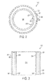
- FIG. 2 illustrates a top-view of an inductor of the motor controller of FIG. 1 ;
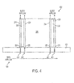
- FIG. 3 illustrates a side cutaway view of an inductor of the motor controller of FIG. 1 ;
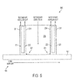
- FIG. 4 illustrates a side cutaway view of a portion of an air cooled motor controller, according to an exemplary embodiment of the present invention
- FIG. 5 illustrates a side cutaway view of a portion of an additional air cooled motor controller, according to an exemplary embodiment of the present invention
- FIG. 6 illustrates a side cutaway view of a portion of the air cooled motor controller of FIG. 5 fitted with an air plenum, according to an exemplary embodiment of the present invention.
- FIG. 7 is a schematic representation of the air cooled motor controller of FIG. 6 .
- air cooled motor controllers which include enhanced cooling through application of airflow from a plurality of air sources.
- exemplary embodiments of the present invention provide inductor assemblies with a reduced weight and complexity that allow for increased heat dissipation as compared to conventional potted inductors.
- the technical effects and benefits of exemplary embodiments include an overall reduced weight and cost of motor controllers while also providing enhanced cooling, which therefore allows for easy integration into aircraft systems.
- the motor controller 100 includes substrate 101.
- the substrate 101 may be a cold plate support substrate formed of a conductive material.
- the conductive material may be any material suitable for support of electronic components and suitable for conducting heat.
- the substrate may be exposed to an air source such that air flows proximate the substrate 101 through a cooling channel 105.
- the motor controller 100 further includes a plurality of power modules 102 arranged on the substrate 101.
- the power modules 102 may be electronic power modules configured to control a motor (not illustrated).
- the power modules 102 may be insulated gate bipolar transistor (IGBT) power modules, each including at least one power transistor such as, for example, an IGBT or the like.
- IGBT insulated gate bipolar transistor
- the motor controller 100 further includes a plurality of inductor assemblies 103 and 104 arranged on the substrate 101.
- the inductor assemblies 103 and 104 may be in electrical communication with one or more of the power modules 102. Furthermore, the inductor assemblies 103 and 104 may be arranged to receive airflow from a plurality of air sources for enhanced air cooling.
- the inductor assemblies 103 and 104 may also be mounted to the substrate 101 using a thermal interface material which allows for heat conduction between the inductor assemblies 103 and 104 and the substrate 101.
- the thermal interface material may include an adhesive backed gap pad.
- the gap pad may be a high performance thermal conductivity gap filler pad such as, for example, SARCON ® -XR-m with a thermal conductivity of about 17 Watt/meter-Kelvin offered by fujipoly ® .
- the high performance thermal conductivity gap filler pad may be formed of silicone, Indium film, and/or any other materials.
- FIGS. 2-3 a more detailed discussion of individual inductor assemblies is provided with reference to FIGS. 2-3 .
- the assembly 103 may include an outer cylindrical housing 201.
- the outer cylindrical housing 201 may be formed of a heat-resistant material, such as thermoplastic.
- the outer cylindrical housing is formed of a cylinder of polyetherimide (PEI) or polyether ether ketone (PEEK).
- the assembly 103 further includes wound inductor core 203 arranged within outer cylindrical housing 201.
- the wound inductor core 203 may be formed of any suitable core material, including ferromagnetic material or laminated core material.
- the assembly 103 further includes inductor windings 202 that are wound about the wound inductor core 203.
- the inductor windings 202 may be formed of conductive wire, for example, stranded or solid-core wire.
- the assembly 103 further includes inner cylindrical housing 204 arranged within the wound inductor core 203.
- the inner cylindrical housing 204 may be formed of the same or similar material as the outer cylindrical housing 201.
- the inner cylindrical housing 204 defines an inner cylindrical cavity 205 disposed to transmit air. For example, cooling air from an air source may be passed through the inner cylindrical cavity 205.
- a first cylindrical gap 221 is defined by the wound inductor core 203 and the outer cylindrical housing 201.
- a second cylindrical gap 222 is defined by the wound inductor core 203 and the inner cylindrical housing 204. The first cylindrical gap 221 and the second cylindrical gap 222 may also be disposed to transmit air.
- air transmitted through the inner cylindrical cavity 205 may be routed to the first cylindrical gap 221 and the second cylindrical gap 222 such that cooling air circulates about the wound inductor core 203.
- cooling air from secondary air source may be routed to the first cylindrical gap 221 and the second cylindrical gap 222.
- FIG. 4 a side cutaway view of a portion of an air cooled motor controller 400 is illustrated.
- the motor controller 400 may be substantially similar to the motor controller 100 as is shown and described with reference to FIG. 1 , for example, including a plurality of inductor assemblies 103 and 104 arranged on a substrate 101.
- the substrate 101 may include a plurality of through-holes 401 arranged therethrough such that the first cylindrical gap 221 and the second cylindrical gap 222 are in fluid communication with a main airflow through channel 105. Therefore, "bleed airflow" may form within the first cylindrical gap 221 and the second cylindrical gap 222 such that the wound inductor 203 is cooled by convection.
- the main airflow may be supplied through channel 105.
- the channel 105 may be provided air from an environmental control system (ECS) of an aircraft. Accordingly, the air from the ECS may be filtered and/or dehumidified to reduce deterioration, corrosion or possibility of electrical short of the wound inductor core 203.
- ECS environmental control system
- the air flow path may be reversed. Fresh air can enter the inductor, flow through gaps 221 and 222 and then enter the main flow path 105. Thus, the inductor cooling flow can form the main airflow.
- a secondary air source may be used to cool the wound inductor core 203 as illustrated in FIGS. 5-7 .
- FIG. 5 illustrates a side cutaway view of a portion of an additional air cooled motor controller 500.
- the motor controller 500 may be somewhat similar to the motor controller 100, for example, including a plurality of inductor assemblies 103 and 104 arranged on a substrate 101.
- a secondary airflow (e.g., from a secondary air source) may be established in the cylindrical cavity 205 in addition to the main airflow flowing from channel 105 proximate the substrate 101.
- the secondary airflow may be routed into the cylindrical cavity 205 and further through a gap 501 in the inner cylindrical housing 204, and into the first cylindrical gap 221 and the second cylindrical gap 222.
- the gap 501 may be a cylindrical gap formed through a gap filler pad (not illustrated) providing structural support and spacing between the inner cylindrical housing 204 and the substrate 101.
- the secondary airflow may flow over the wound inductor core 203 to provide cooling. Circulated air may exit the first cylindrical gap 221 and the second cylindrical gap 222.
- the secondary airflow may be provided from a secondary air source, such as a filtered air source. Therefore, ECS air may be used for the main airflow from channel 105, and the secondary air source may be used directly as the secondary air flow. Because the secondary air source may provide filtered air, deterioration of the wound inductor core 203 may be reduced.
- the air flow direction may be reversed, where flow enters through channels 221 and 222 and exits through 205.
- the secondary airflow may be provided from a secondary air source.
- an air plenum or other routing device may be used to route air from the secondary air source to limit contamination from a main airflow from channel 105.
- air cooled motor controllers fitted with air plenums are described in more detail with reference to FIGS. 6-7 .
- FIG. 6 illustrates a side cutaway view of a portion of the air cooled motor controller of FIG. 5 fitted with an air plenum 601.
- the air plenum 601 may be arranged on the inductor assemblies 103.
- the air plenum 601 includes a first airflow chamber 610 configured to transmit air from a secondary air source to inner cylindrical cavities 205a and 205b of inductor assemblies 103.
- the first airflow chamber 610 may include a plurality of cylindrical ports 611 configured to mate with inner cylindrical housings 204a and 204b of inductor assemblies 103. Accordingly, air flowing from the secondary air source may enter the first airflow chamber 610, and may exit through cylindrical ports 611 into associated inner cylindrical cavities 205a and 205b.
- the air plenum 601 further includes second airflow chamber 620 proximate the first airflow chamber 610 and the inductor assemblies 103.
- the second airflow chamber 620 may include a plurality of toroidal ports 612 configured to mate with the outer cylindrical housings 201 a and 201b of the inductor assemblies 103. Accordingly, air flowing through the first cylindrical gaps 221 a and 221b and the second cylindrical gaps 222a and 222b may exit through the toroidal ports 612.
- the motor controller includes a substrate 101, a plurality of inductor assemblies 103 arranged on the substrate 101, and an air plenum 601 arranged on the plurality of inductor assemblies.
- the air plenum may be configured to route air from secondary air source 622 through inductor assemblies 103 and direct associated exhaust away from the inductor assemblies 103.
- the substrate 101 is arranged proximate a main airflow channel 105 receiving airflow from a primary or main air source 621, for example, an Environmental Control System of an aircraft.
Landscapes
- Engineering & Computer Science (AREA)
- Physics & Mathematics (AREA)
- Thermal Sciences (AREA)
- Microelectronics & Electronic Packaging (AREA)
- Mechanical Engineering (AREA)
- General Engineering & Computer Science (AREA)
- Motor Or Generator Cooling System (AREA)
Abstract
Description
- The present invention is generally directed to motor controllers, and more particularly, exemplary embodiments of the present invention are directed to air cooled motor controllers drawing cooling air from a plurality of air sources.
- Conventionally, motor controllers are cooled by directing air flow over their components. Air flow is directed to various heat dissipating sources, for example, heat sinks. However, in emerging motor controllers there is increased power dissipation requirements, especially from insulated gate bipolar transistor power modules and associated inductors. The associated inductors are typically potted with a potting compound which requires a metal housing for structural support. Both the metal housing and potting compound add weight and cost to an entire inductor assembly. Furthermore, the metal housing and potting compound limit airflow about the actual inductors, and therefore, limit heat dissipation and increase airflow requirements to meet optimum operating temperature ranges.
- According to an exemplary embodiment of the present invention, an air cooled motor controller includes a substrate and at least one inductor assembly arranged on the substrate. The at least one inductor assembly includes an outer cylindrical housing, a wound inductor core arranged within the outer cylindrical housing, and an inner cylindrical housing arranged within the wound inductor core. The inner cylindrical housing defines an inner cylindrical cavity configured to transmit air. Also, the outer cylindrical housing and the inner cylindrical housing define at least one cylindrical gap in fluid communication with the inner cylindrical cavity and configured to transmit air. The motor controller also includes at least one air source in fluid communication with the at least one cylindrical gap.
- The subject matter which is regarded as the invention is particularly pointed out and distinctly claimed in the claims at the conclusion of the specification. The foregoing and other features, and advantages of the invention are apparent from the following detailed description taken in conjunction with the accompanying drawings in which like elements are numbered alike:
-
FIG. 1 illustrates an air cooled motor controller, according to an exemplary embodiment of the present invention; -
FIG. 2 illustrates a top-view of an inductor of the motor controller ofFIG. 1 ; -
FIG. 3 illustrates a side cutaway view of an inductor of the motor controller ofFIG. 1 ; -
FIG. 4 illustrates a side cutaway view of a portion of an air cooled motor controller, according to an exemplary embodiment of the present invention; -
FIG. 5 illustrates a side cutaway view of a portion of an additional air cooled motor controller, according to an exemplary embodiment of the present invention; -
FIG. 6 illustrates a side cutaway view of a portion of the air cooled motor controller ofFIG. 5 fitted with an air plenum, according to an exemplary embodiment of the present invention; and -
FIG. 7 is a schematic representation of the air cooled motor controller ofFIG. 6 . - According to exemplary embodiments of the present invention, air cooled motor controllers are provided which include enhanced cooling through application of airflow from a plurality of air sources. Furthermore, exemplary embodiments of the present invention provide inductor assemblies with a reduced weight and complexity that allow for increased heat dissipation as compared to conventional potted inductors. The technical effects and benefits of exemplary embodiments include an overall reduced weight and cost of motor controllers while also providing enhanced cooling, which therefore allows for easy integration into aircraft systems.
- Turning to
FIG. 1 , an air cooledmotor controller 100 is illustrated. Themotor controller 100 includessubstrate 101. Thesubstrate 101 may be a cold plate support substrate formed of a conductive material. The conductive material may be any material suitable for support of electronic components and suitable for conducting heat. As illustrated, the substrate may be exposed to an air source such that air flows proximate thesubstrate 101 through acooling channel 105. - The
motor controller 100 further includes a plurality ofpower modules 102 arranged on thesubstrate 101. Thepower modules 102 may be electronic power modules configured to control a motor (not illustrated). According to one exemplary embodiment, thepower modules 102 may be insulated gate bipolar transistor (IGBT) power modules, each including at least one power transistor such as, for example, an IGBT or the like. - The
motor controller 100 further includes a plurality ofinductor assemblies substrate 101. The inductor assemblies 103 and 104 may be in electrical communication with one or more of thepower modules 102. Furthermore, the inductor assemblies 103 and 104 may be arranged to receive airflow from a plurality of air sources for enhanced air cooling. Moreover, the inductor assemblies 103 and 104 may also be mounted to thesubstrate 101 using a thermal interface material which allows for heat conduction between theinductor assemblies substrate 101. For example, the thermal interface material may include an adhesive backed gap pad. According to one exemplary embodiment, the gap pad may be a high performance thermal conductivity gap filler pad such as, for example, SARCON®-XR-m with a thermal conductivity of about 17 Watt/meter-Kelvin offered by fujipoly®. In embodiments, the high performance thermal conductivity gap filler pad may be formed of silicone, Indium film, and/or any other materials. - Hereinafter, a more detailed discussion of individual inductor assemblies is provided with reference to
FIGS. 2-3 . - Turning to
FIGS. 2 and 3 , a top-view and a side cutaway view ofinductor assembly 103 are illustrated. It is to be understood that although a detailed description ofinductor assembly 103 is being made with reference toFIGS. 2 and 3 , the inductor assembly 104 (FIG. 1 ) may be of substantially the same form as illustrated with respect toinductor assembly 103 inFIGS. 2 and 3 , albeit of differing scale and/or dimension. Theassembly 103 may include an outercylindrical housing 201. The outercylindrical housing 201 may be formed of a heat-resistant material, such as thermoplastic. According to one exemplary embodiment, the outer cylindrical housing is formed of a cylinder of polyetherimide (PEI) or polyether ether ketone (PEEK). - The
assembly 103 further includeswound inductor core 203 arranged within outercylindrical housing 201. Thewound inductor core 203 may be formed of any suitable core material, including ferromagnetic material or laminated core material. Theassembly 103 further includesinductor windings 202 that are wound about thewound inductor core 203. Theinductor windings 202 may be formed of conductive wire, for example, stranded or solid-core wire. - The
assembly 103 further includes innercylindrical housing 204 arranged within thewound inductor core 203. The innercylindrical housing 204 may be formed of the same or similar material as the outercylindrical housing 201. Furthermore, the innercylindrical housing 204 defines an innercylindrical cavity 205 disposed to transmit air. For example, cooling air from an air source may be passed through the innercylindrical cavity 205. Moreover, as illustrated, a firstcylindrical gap 221 is defined by thewound inductor core 203 and the outercylindrical housing 201. Additionally, a secondcylindrical gap 222 is defined by thewound inductor core 203 and the innercylindrical housing 204. The firstcylindrical gap 221 and the secondcylindrical gap 222 may also be disposed to transmit air. For example, air transmitted through the innercylindrical cavity 205 may be routed to the firstcylindrical gap 221 and the secondcylindrical gap 222 such that cooling air circulates about thewound inductor core 203. Alternatively, cooling air from secondary air source may be routed to the firstcylindrical gap 221 and the secondcylindrical gap 222. - Hereinafter, circulation of cooling air through inductor assemblies is described in detail with reference to
FIGS. 4-6 . - Turning to
FIG. 4 , a side cutaway view of a portion of an air cooledmotor controller 400 is illustrated. Themotor controller 400 may be substantially similar to themotor controller 100 as is shown and described with reference toFIG. 1 , for example, including a plurality ofinductor assemblies substrate 101. As illustrated, thesubstrate 101 may include a plurality of through-holes 401 arranged therethrough such that the firstcylindrical gap 221 and the secondcylindrical gap 222 are in fluid communication with a main airflow throughchannel 105. Therefore, "bleed airflow" may form within the firstcylindrical gap 221 and the secondcylindrical gap 222 such that thewound inductor 203 is cooled by convection. - The main airflow may be supplied through
channel 105. Thechannel 105 may be provided air from an environmental control system (ECS) of an aircraft. Accordingly, the air from the ECS may be filtered and/or dehumidified to reduce deterioration, corrosion or possibility of electrical short of thewound inductor core 203. In addition, the air flow path may be reversed. Fresh air can enter the inductor, flow throughgaps main flow path 105. Thus, the inductor cooling flow can form the main airflow. Alternatively, a secondary air source may be used to cool thewound inductor core 203 as illustrated inFIGS. 5-7 . -
FIG. 5 illustrates a side cutaway view of a portion of an additional air cooledmotor controller 500. Themotor controller 500 may be somewhat similar to themotor controller 100, for example, including a plurality ofinductor assemblies substrate 101. As illustrated, a secondary airflow (e.g., from a secondary air source) may be established in thecylindrical cavity 205 in addition to the main airflow flowing fromchannel 105 proximate thesubstrate 101. The secondary airflow may be routed into thecylindrical cavity 205 and further through agap 501 in the innercylindrical housing 204, and into the firstcylindrical gap 221 and the secondcylindrical gap 222. Thegap 501 may be a cylindrical gap formed through a gap filler pad (not illustrated) providing structural support and spacing between the innercylindrical housing 204 and thesubstrate 101. The secondary airflow may flow over thewound inductor core 203 to provide cooling. Circulated air may exit the firstcylindrical gap 221 and the secondcylindrical gap 222. The secondary airflow may be provided from a secondary air source, such as a filtered air source. Therefore, ECS air may be used for the main airflow fromchannel 105, and the secondary air source may be used directly as the secondary air flow. Because the secondary air source may provide filtered air, deterioration of thewound inductor core 203 may be reduced. The air flow direction may be reversed, where flow enters throughchannels - As described above, the secondary airflow may be provided from a secondary air source. Accordingly, an air plenum or other routing device may be used to route air from the secondary air source to limit contamination from a main airflow from
channel 105. Hereinafter, air cooled motor controllers fitted with air plenums are described in more detail with reference toFIGS. 6-7 . -
FIG. 6 illustrates a side cutaway view of a portion of the air cooled motor controller ofFIG. 5 fitted with anair plenum 601. As illustrated, theair plenum 601 may be arranged on theinductor assemblies 103. Theair plenum 601 includes afirst airflow chamber 610 configured to transmit air from a secondary air source to innercylindrical cavities inductor assemblies 103. Thefirst airflow chamber 610 may include a plurality ofcylindrical ports 611 configured to mate with innercylindrical housings inductor assemblies 103. Accordingly, air flowing from the secondary air source may enter thefirst airflow chamber 610, and may exit throughcylindrical ports 611 into associated innercylindrical cavities - The
air plenum 601 further includessecond airflow chamber 620 proximate thefirst airflow chamber 610 and theinductor assemblies 103. Thesecond airflow chamber 620 may include a plurality oftoroidal ports 612 configured to mate with the outercylindrical housings inductor assemblies 103. Accordingly, air flowing through the firstcylindrical gaps cylindrical gaps toroidal ports 612. - Although particularly illustrated as having air entering through the
first airflow chamber 610 and exiting through thesecond airflow chamber 620, it should be understood that the same is easily reversed according to any desired implementation. - Turning now to
FIG. 7 , a simplified schematic of the air cooledmotor controller 500 is illustrated. The motor controller includes asubstrate 101, a plurality ofinductor assemblies 103 arranged on thesubstrate 101, and anair plenum 601 arranged on the plurality of inductor assemblies. The air plenum may be configured to route air fromsecondary air source 622 throughinductor assemblies 103 and direct associated exhaust away from theinductor assemblies 103. Furthermore, thesubstrate 101 is arranged proximate amain airflow channel 105 receiving airflow from a primary ormain air source 621, for example, an Environmental Control System of an aircraft. - While the invention has been described in detail in connection with only a limited number of embodiments, it should be readily understood that the invention is not limited to such disclosed embodiments. Rather, the invention can be modified to incorporate any number of variations, alterations, substitutions or equivalent arrangements not heretofore described, but which are commensurate with the spirit and scope of the invention. Additionally, while various embodiments of the invention have been described, it is to be understood that aspects of the invention may include only some of the described embodiments. Accordingly, the invention is not to be seen as limited by the foregoing description, but is only limited by the scope of the appended claims.
Claims (15)
- An air cooled motor controller (100), comprising:a substrate (101);at least one inductor assembly (103) arranged on the substrate (101), wherein the at least one inductor assembly (103) includes an outer cylindrical housing (201), a wound inductor core (203) arranged within the outer cylindrical housing (201), and an inner cylindrical housing (204) arranged within the wound inductor core (203), wherein the inner cylindrical housing (204) defines an inner cylindrical cavity (205) configured to transmit air, and wherein the outer cylindrical housing (201) and the inner cylindrical housing (204) define at least one cylindrical gap (221) in fluid communication with the inner cylindrical cavity (205) and configured to transmit air;at least one air source in fluid communication with the at least one cylindrical gap (221).
- The motor controller of claim 1, wherein the substrate (101) comprises a plurality of through holes arranged therethrough that are configured to transmit air between the at least one air source and the at least one cylindrical gap, and preferably wherein the at least one air source is an Environmental Control System of an aircraft.
- The motor controller of claim 1, further comprising:an air plenum (601) arranged on the at least one inductor assembly (103).
- The motor controller of claim 3, wherein the air plenum (601) is configured to transmit air to the inner cylindrical cavity (205) from the at least one air source.
- The motor controller of claim 4, wherein the air plenum (601) comprises:a first airflow chamber (610) in fluid communication between the at least one air source and the inner cylindrical cavity (205); anda second airflow chamber (620) in fluid communication with the at least one cylindrical gap and configured to transmit exhaust air from the at least one cylindrical gap (221).
- The motor controller of claim 3, wherein the air plenum (601) is configured to transmit air to the at least one cylindrical gap (221) from the at least one air source.
- The motor controller of claim 6, wherein the air plenum comprises:a first airflow chamber (610) in fluid communication between the at least one air source and the at least one cylindrical gap (221); anda second airflow chamber (620) in fluid communication with the inner cylindrical cavity (205) and configured to transmit exhaust air from the inner cylindrical cavity (205).
- The motor controller of claim 3, wherein the air plenum (601) comprises:at least one cylindrical port (611) in fluid communication with the inner cylindrical cavity; andat least one toroidal port (612) in fluid communication with the at least one cylindrical gap.
- The motor controller of claim 1, further comprising:a plurality of power modules (102) arranged on the substrate (101) and in electrical communication with the at least one inductor assembly (103).
- The motor controller of claim 9, wherein the plurality of power modules (102) are Insulated Gate Bipolar Transistor power modules.
- The motor controller of claim 1, wherein the outer cylindrical housing (201) and the inner cylindrical housing are formed of thermoplastic, and preferably wherein the thermo plastic is polyetherimide (PEI) or polyether ether ketone (PEEK) based thermoplastic, or wherein the wound inductor core is a ferromagnetic inductor core or a laminated inductor core.
- The motor controller of claim 1, further comprising:a plurality of inductor assemblies (103) arranged on the substrate (101), wherein each inductor assembly (103) of the plurality of inductor assemblies includes an outer cylindrical housing (201), a wound inductor core (203) arranged within the outer cylindrical housing (201), and inner cylindrical housing (204) arranged within the wound inductor core, wherein the inner cylindrical housing (204) defines an inner cylindrical cavity (205) configured to transmit air, and wherein the outer cylindrical housing (201) and the inner cylindrical housing (204) define at least one cylindrical gap (221) in fluid communication with the inner cylindrical cavity (205) and configured to transmit air.
- The motor controller of claim 12, further comprising:an air plenum (601) arranged on the plurality of inductor assemblies (103) and configured to transmit air to inner cylindrical cavities (205) of the plurality of inductor assemblies (103) from the at least one air source.
- The motor controller of claim 13, wherein the air plenum comprises:a first airflow chamber (610) in fluid communication between the at least one air source and the inner cylindrical cavities (205); anda second airflow chamber (620) in fluid communication with the cylindrical gaps (221) of the plurality of inductor assemblies and configured to transmit exhaust air from the cylindrical gaps.
- The motor controller of any of claims 5, 7 or 14, further comprising:an airflow channel proximate the substrate (101); anda second air source in fluid communication with the substrate (101), wherein the second air source is an Environmental Control System of an aircraft and the at least one air source is a dedicated filtered cooling air source.
Applications Claiming Priority (1)
| Application Number | Priority Date | Filing Date | Title |
|---|---|---|---|
| US13/425,045 US9175694B2 (en) | 2012-03-20 | 2012-03-20 | Air cooled motor controllers |
Publications (3)
| Publication Number | Publication Date |
|---|---|
| EP2642131A2 true EP2642131A2 (en) | 2013-09-25 |
| EP2642131A3 EP2642131A3 (en) | 2017-01-04 |
| EP2642131B1 EP2642131B1 (en) | 2018-05-02 |
Family
ID=48092678
Family Applications (1)
| Application Number | Title | Priority Date | Filing Date |
|---|---|---|---|
| EP13160039.7A Active EP2642131B1 (en) | 2012-03-20 | 2013-03-19 | Air cooled motor controllers |
Country Status (2)
| Country | Link |
|---|---|
| US (1) | US9175694B2 (en) |
| EP (1) | EP2642131B1 (en) |
Cited By (1)
| Publication number | Priority date | Publication date | Assignee | Title |
|---|---|---|---|---|
| EP3499524A1 (en) * | 2017-12-12 | 2019-06-19 | Hamilton Sundstrand Corporation | Systems and methods for cooling toroidal magnetics |
Families Citing this family (2)
| Publication number | Priority date | Publication date | Assignee | Title |
|---|---|---|---|---|
| US10201119B2 (en) | 2015-06-02 | 2019-02-05 | Hamilton Sundstrand Corporation | System and method of alternate cooling of a liquid cooled motor controller |
| US10270231B2 (en) | 2017-06-20 | 2019-04-23 | Hamilton Sundstrand Corporation | Integrated contactor mounting post |
Family Cites Families (13)
| Publication number | Priority date | Publication date | Assignee | Title |
|---|---|---|---|---|
| IT8221582U1 (en) * | 1982-04-16 | 1983-10-16 | Sirten | INDUCTANCE COIL. |
| US5202584A (en) * | 1991-08-30 | 1993-04-13 | Bba Canada Limited | High energy dissipation harmonic filter reactor |
| US5905647A (en) * | 1997-01-20 | 1999-05-18 | Kabushiki Kaisha Toshiba | Inverter with incorporated filter circuit and improved component cooling arrangement |
| US6019165A (en) * | 1998-05-18 | 2000-02-01 | Batchelder; John Samuel | Heat exchange apparatus |
| US6408937B1 (en) * | 2000-11-15 | 2002-06-25 | Sanjay K. Roy | Active cold plate/heat sink |
| US7209355B2 (en) * | 2002-05-15 | 2007-04-24 | Matsushita Electric Industrial Co., Ltd. | Cooling device and an electronic apparatus including the same |
| TW595307B (en) * | 2002-11-08 | 2004-06-21 | Jiun-Guang Luo | Centralized diversion and heat dissipating device |
| DE10258765B4 (en) * | 2002-12-16 | 2006-02-09 | Wacker Construction Equipment Ag | Frequency converter with fan cooling |
| CN100499974C (en) * | 2005-08-10 | 2009-06-10 | 富准精密工业(深圳)有限公司 | Integral liquid-cooled radiator |
| CN100493318C (en) * | 2005-11-08 | 2009-05-27 | 富准精密工业(深圳)有限公司 | An integral liquid cooling heat radiator |
| US7511957B2 (en) * | 2006-05-25 | 2009-03-31 | International Business Machines Corporation | Methods for fabricating a cooled electronic module employing a thermally conductive return manifold structure sealed to the periphery of a surface to be cooled |
| US8289711B2 (en) * | 2010-08-20 | 2012-10-16 | Hamilton Sundstrand Corporation | Integrated thermal packaging of high power motor controller |
| US9306432B2 (en) * | 2012-10-31 | 2016-04-05 | Hamilton Sundstrand Corporation | Stator cooling channel tolerant to localized blockage |
-
2012
- 2012-03-20 US US13/425,045 patent/US9175694B2/en active Active
-
2013
- 2013-03-19 EP EP13160039.7A patent/EP2642131B1/en active Active
Non-Patent Citations (1)
| Title |
|---|
| None |
Cited By (2)
| Publication number | Priority date | Publication date | Assignee | Title |
|---|---|---|---|---|
| EP3499524A1 (en) * | 2017-12-12 | 2019-06-19 | Hamilton Sundstrand Corporation | Systems and methods for cooling toroidal magnetics |
| US10892082B2 (en) | 2017-12-12 | 2021-01-12 | Hamilton Sundstrand Corporation | Systems and methods for cooling toroidal magnetics |
Also Published As
| Publication number | Publication date |
|---|---|
| EP2642131B1 (en) | 2018-05-02 |
| EP2642131A3 (en) | 2017-01-04 |
| US20130250516A1 (en) | 2013-09-26 |
| US9175694B2 (en) | 2015-11-03 |
Similar Documents
| Publication | Publication Date | Title |
|---|---|---|
| US11824406B2 (en) | Motor drive unit | |
| CN104053339B (en) | Electric cabinet with improved radiating | |
| US9515530B2 (en) | Stator module and magnetic field generating structure thereof | |
| CN104582357B (en) | Electronic installation with water-protected enclosure | |
| US8472194B2 (en) | Solid state switching device with integral heatsink | |
| US9380733B2 (en) | Cooling device and power module equipped with cooling device | |
| US20120300406A1 (en) | Heat radiation device and electronic equipment using the same | |
| WO2014103298A1 (en) | Reactor | |
| US9331550B2 (en) | Air cooling of a motor using radially mounted fan | |
| EP2642131B1 (en) | Air cooled motor controllers | |
| CN106205963B (en) | The cooling device of transformer | |
| US10064309B2 (en) | Shelf thermostat device and thermostat system | |
| US20130093270A1 (en) | High temperature environment capable motor controller | |
| CN105612824A (en) | Electric module, electric system comprising such an electric module, and corresponding production methods | |
| US10617041B2 (en) | Multi-compartment electrical apparatus with shared cooling assembly | |
| KR101969099B1 (en) | Transformer embedded with thermally conductive member | |
| CN115209701B (en) | A heat dissipation duct structure and power grid simulator | |
| CN113056160A (en) | Cooling device for electronic device and data processing system including the same | |
| EP4061533B1 (en) | Thermal management for thermal cyclers using air tubes | |
| US20230200030A1 (en) | Power electronics system having a housing, a cooling device, a power semiconductor module and a capacitor device | |
| US10806020B2 (en) | Device for receiving an electronics assembly | |
| CN218160074U (en) | Heat radiation structure and circuit breaker | |
| EP3745834A1 (en) | Apparatus for conducting heat | |
| JP2008258513A (en) | Liquid cooling heat sink device | |
| KR20240074662A (en) | Linear motor, positioning device, processing device, device manufacturing method |
Legal Events
| Date | Code | Title | Description |
|---|---|---|---|
| PUAI | Public reference made under article 153(3) epc to a published international application that has entered the european phase |
Free format text: ORIGINAL CODE: 0009012 |
|
| AK | Designated contracting states |
Kind code of ref document: A2 Designated state(s): AL AT BE BG CH CY CZ DE DK EE ES FI FR GB GR HR HU IE IS IT LI LT LU LV MC MK MT NL NO PL PT RO RS SE SI SK SM TR |
|
| AX | Request for extension of the european patent |
Extension state: BA ME |
|
| PUAL | Search report despatched |
Free format text: ORIGINAL CODE: 0009013 |
|
| AK | Designated contracting states |
Kind code of ref document: A3 Designated state(s): AL AT BE BG CH CY CZ DE DK EE ES FI FR GB GR HR HU IE IS IT LI LT LU LV MC MK MT NL NO PL PT RO RS SE SI SK SM TR |
|
| AX | Request for extension of the european patent |
Extension state: BA ME |
|
| RIC1 | Information provided on ipc code assigned before grant |
Ipc: F04D 29/58 20060101AFI20161130BHEP Ipc: H02K 17/30 20060101ALN20161130BHEP Ipc: H02K 5/20 20060101ALI20161130BHEP Ipc: H05K 7/20 20060101ALI20161130BHEP |
|
| STAA | Information on the status of an ep patent application or granted ep patent |
Free format text: STATUS: REQUEST FOR EXAMINATION WAS MADE |
|
| 17P | Request for examination filed |
Effective date: 20170630 |
|
| RBV | Designated contracting states (corrected) |
Designated state(s): AL AT BE BG CH CY CZ DE DK EE ES FI FR GB GR HR HU IE IS IT LI LT LU LV MC MK MT NL NO PL PT RO RS SE SI SK SM TR |
|
| GRAP | Despatch of communication of intention to grant a patent |
Free format text: ORIGINAL CODE: EPIDOSNIGR1 |
|
| STAA | Information on the status of an ep patent application or granted ep patent |
Free format text: STATUS: GRANT OF PATENT IS INTENDED |
|
| RIC1 | Information provided on ipc code assigned before grant |
Ipc: H02K 17/30 20060101ALN20171020BHEP Ipc: F04D 29/58 20060101AFI20171020BHEP Ipc: H05K 7/20 20060101ALI20171020BHEP Ipc: H02K 5/20 20060101ALI20171020BHEP |
|
| INTG | Intention to grant announced |
Effective date: 20171108 |
|
| GRAS | Grant fee paid |
Free format text: ORIGINAL CODE: EPIDOSNIGR3 |
|
| GRAA | (expected) grant |
Free format text: ORIGINAL CODE: 0009210 |
|
| STAA | Information on the status of an ep patent application or granted ep patent |
Free format text: STATUS: THE PATENT HAS BEEN GRANTED |
|
| AK | Designated contracting states |
Kind code of ref document: B1 Designated state(s): AL AT BE BG CH CY CZ DE DK EE ES FI FR GB GR HR HU IE IS IT LI LT LU LV MC MK MT NL NO PL PT RO RS SE SI SK SM TR |
|
| REG | Reference to a national code |
Ref country code: GB Ref legal event code: FG4D |
|
| REG | Reference to a national code |
Ref country code: CH Ref legal event code: EP Ref country code: AT Ref legal event code: REF Ref document number: 995568 Country of ref document: AT Kind code of ref document: T Effective date: 20180515 |
|
| REG | Reference to a national code |
Ref country code: DE Ref legal event code: R096 Ref document number: 602013036777 Country of ref document: DE Ref country code: IE Ref legal event code: FG4D |
|
| REG | Reference to a national code |
Ref country code: NL Ref legal event code: MP Effective date: 20180502 |
|
| REG | Reference to a national code |
Ref country code: LT Ref legal event code: MG4D |
|
| PG25 | Lapsed in a contracting state [announced via postgrant information from national office to epo] |
Ref country code: FI Free format text: LAPSE BECAUSE OF FAILURE TO SUBMIT A TRANSLATION OF THE DESCRIPTION OR TO PAY THE FEE WITHIN THE PRESCRIBED TIME-LIMIT Effective date: 20180502 Ref country code: LT Free format text: LAPSE BECAUSE OF FAILURE TO SUBMIT A TRANSLATION OF THE DESCRIPTION OR TO PAY THE FEE WITHIN THE PRESCRIBED TIME-LIMIT Effective date: 20180502 Ref country code: BG Free format text: LAPSE BECAUSE OF FAILURE TO SUBMIT A TRANSLATION OF THE DESCRIPTION OR TO PAY THE FEE WITHIN THE PRESCRIBED TIME-LIMIT Effective date: 20180802 Ref country code: SE Free format text: LAPSE BECAUSE OF FAILURE TO SUBMIT A TRANSLATION OF THE DESCRIPTION OR TO PAY THE FEE WITHIN THE PRESCRIBED TIME-LIMIT Effective date: 20180502 Ref country code: NO Free format text: LAPSE BECAUSE OF FAILURE TO SUBMIT A TRANSLATION OF THE DESCRIPTION OR TO PAY THE FEE WITHIN THE PRESCRIBED TIME-LIMIT Effective date: 20180802 Ref country code: ES Free format text: LAPSE BECAUSE OF FAILURE TO SUBMIT A TRANSLATION OF THE DESCRIPTION OR TO PAY THE FEE WITHIN THE PRESCRIBED TIME-LIMIT Effective date: 20180502 |
|
| PG25 | Lapsed in a contracting state [announced via postgrant information from national office to epo] |
Ref country code: NL Free format text: LAPSE BECAUSE OF FAILURE TO SUBMIT A TRANSLATION OF THE DESCRIPTION OR TO PAY THE FEE WITHIN THE PRESCRIBED TIME-LIMIT Effective date: 20180502 Ref country code: GR Free format text: LAPSE BECAUSE OF FAILURE TO SUBMIT A TRANSLATION OF THE DESCRIPTION OR TO PAY THE FEE WITHIN THE PRESCRIBED TIME-LIMIT Effective date: 20180803 Ref country code: RS Free format text: LAPSE BECAUSE OF FAILURE TO SUBMIT A TRANSLATION OF THE DESCRIPTION OR TO PAY THE FEE WITHIN THE PRESCRIBED TIME-LIMIT Effective date: 20180502 Ref country code: HR Free format text: LAPSE BECAUSE OF FAILURE TO SUBMIT A TRANSLATION OF THE DESCRIPTION OR TO PAY THE FEE WITHIN THE PRESCRIBED TIME-LIMIT Effective date: 20180502 Ref country code: LV Free format text: LAPSE BECAUSE OF FAILURE TO SUBMIT A TRANSLATION OF THE DESCRIPTION OR TO PAY THE FEE WITHIN THE PRESCRIBED TIME-LIMIT Effective date: 20180502 |
|
| REG | Reference to a national code |
Ref country code: AT Ref legal event code: MK05 Ref document number: 995568 Country of ref document: AT Kind code of ref document: T Effective date: 20180502 |
|
| PG25 | Lapsed in a contracting state [announced via postgrant information from national office to epo] |
Ref country code: DK Free format text: LAPSE BECAUSE OF FAILURE TO SUBMIT A TRANSLATION OF THE DESCRIPTION OR TO PAY THE FEE WITHIN THE PRESCRIBED TIME-LIMIT Effective date: 20180502 Ref country code: AT Free format text: LAPSE BECAUSE OF FAILURE TO SUBMIT A TRANSLATION OF THE DESCRIPTION OR TO PAY THE FEE WITHIN THE PRESCRIBED TIME-LIMIT Effective date: 20180502 Ref country code: EE Free format text: LAPSE BECAUSE OF FAILURE TO SUBMIT A TRANSLATION OF THE DESCRIPTION OR TO PAY THE FEE WITHIN THE PRESCRIBED TIME-LIMIT Effective date: 20180502 Ref country code: SK Free format text: LAPSE BECAUSE OF FAILURE TO SUBMIT A TRANSLATION OF THE DESCRIPTION OR TO PAY THE FEE WITHIN THE PRESCRIBED TIME-LIMIT Effective date: 20180502 Ref country code: CZ Free format text: LAPSE BECAUSE OF FAILURE TO SUBMIT A TRANSLATION OF THE DESCRIPTION OR TO PAY THE FEE WITHIN THE PRESCRIBED TIME-LIMIT Effective date: 20180502 Ref country code: RO Free format text: LAPSE BECAUSE OF FAILURE TO SUBMIT A TRANSLATION OF THE DESCRIPTION OR TO PAY THE FEE WITHIN THE PRESCRIBED TIME-LIMIT Effective date: 20180502 Ref country code: PL Free format text: LAPSE BECAUSE OF FAILURE TO SUBMIT A TRANSLATION OF THE DESCRIPTION OR TO PAY THE FEE WITHIN THE PRESCRIBED TIME-LIMIT Effective date: 20180502 |
|
| REG | Reference to a national code |
Ref country code: DE Ref legal event code: R097 Ref document number: 602013036777 Country of ref document: DE |
|
| PG25 | Lapsed in a contracting state [announced via postgrant information from national office to epo] |
Ref country code: SM Free format text: LAPSE BECAUSE OF FAILURE TO SUBMIT A TRANSLATION OF THE DESCRIPTION OR TO PAY THE FEE WITHIN THE PRESCRIBED TIME-LIMIT Effective date: 20180502 Ref country code: IT Free format text: LAPSE BECAUSE OF FAILURE TO SUBMIT A TRANSLATION OF THE DESCRIPTION OR TO PAY THE FEE WITHIN THE PRESCRIBED TIME-LIMIT Effective date: 20180502 |
|
| PLBE | No opposition filed within time limit |
Free format text: ORIGINAL CODE: 0009261 |
|
| STAA | Information on the status of an ep patent application or granted ep patent |
Free format text: STATUS: NO OPPOSITION FILED WITHIN TIME LIMIT |
|
| 26N | No opposition filed |
Effective date: 20190205 |
|
| PG25 | Lapsed in a contracting state [announced via postgrant information from national office to epo] |
Ref country code: SI Free format text: LAPSE BECAUSE OF FAILURE TO SUBMIT A TRANSLATION OF THE DESCRIPTION OR TO PAY THE FEE WITHIN THE PRESCRIBED TIME-LIMIT Effective date: 20180502 |
|
| REG | Reference to a national code |
Ref country code: DE Ref legal event code: R119 Ref document number: 602013036777 Country of ref document: DE |
|
| PG25 | Lapsed in a contracting state [announced via postgrant information from national office to epo] |
Ref country code: MC Free format text: LAPSE BECAUSE OF FAILURE TO SUBMIT A TRANSLATION OF THE DESCRIPTION OR TO PAY THE FEE WITHIN THE PRESCRIBED TIME-LIMIT Effective date: 20180502 |
|
| REG | Reference to a national code |
Ref country code: CH Ref legal event code: PL |
|
| PG25 | Lapsed in a contracting state [announced via postgrant information from national office to epo] |
Ref country code: LU Free format text: LAPSE BECAUSE OF NON-PAYMENT OF DUE FEES Effective date: 20190319 Ref country code: AL Free format text: LAPSE BECAUSE OF FAILURE TO SUBMIT A TRANSLATION OF THE DESCRIPTION OR TO PAY THE FEE WITHIN THE PRESCRIBED TIME-LIMIT Effective date: 20180502 |
|
| REG | Reference to a national code |
Ref country code: BE Ref legal event code: MM Effective date: 20190331 |
|
| PG25 | Lapsed in a contracting state [announced via postgrant information from national office to epo] |
Ref country code: IE Free format text: LAPSE BECAUSE OF NON-PAYMENT OF DUE FEES Effective date: 20190319 Ref country code: LI Free format text: LAPSE BECAUSE OF NON-PAYMENT OF DUE FEES Effective date: 20190331 Ref country code: DE Free format text: LAPSE BECAUSE OF NON-PAYMENT OF DUE FEES Effective date: 20191001 Ref country code: CH Free format text: LAPSE BECAUSE OF NON-PAYMENT OF DUE FEES Effective date: 20190331 |
|
| PG25 | Lapsed in a contracting state [announced via postgrant information from national office to epo] |
Ref country code: BE Free format text: LAPSE BECAUSE OF NON-PAYMENT OF DUE FEES Effective date: 20190331 |
|
| PG25 | Lapsed in a contracting state [announced via postgrant information from national office to epo] |
Ref country code: TR Free format text: LAPSE BECAUSE OF FAILURE TO SUBMIT A TRANSLATION OF THE DESCRIPTION OR TO PAY THE FEE WITHIN THE PRESCRIBED TIME-LIMIT Effective date: 20180502 |
|
| PG25 | Lapsed in a contracting state [announced via postgrant information from national office to epo] |
Ref country code: PT Free format text: LAPSE BECAUSE OF FAILURE TO SUBMIT A TRANSLATION OF THE DESCRIPTION OR TO PAY THE FEE WITHIN THE PRESCRIBED TIME-LIMIT Effective date: 20180903 Ref country code: MT Free format text: LAPSE BECAUSE OF NON-PAYMENT OF DUE FEES Effective date: 20190319 |
|
| PG25 | Lapsed in a contracting state [announced via postgrant information from national office to epo] |
Ref country code: CY Free format text: LAPSE BECAUSE OF FAILURE TO SUBMIT A TRANSLATION OF THE DESCRIPTION OR TO PAY THE FEE WITHIN THE PRESCRIBED TIME-LIMIT Effective date: 20180502 |
|
| PG25 | Lapsed in a contracting state [announced via postgrant information from national office to epo] |
Ref country code: IS Free format text: LAPSE BECAUSE OF FAILURE TO SUBMIT A TRANSLATION OF THE DESCRIPTION OR TO PAY THE FEE WITHIN THE PRESCRIBED TIME-LIMIT Effective date: 20180902 |
|
| PG25 | Lapsed in a contracting state [announced via postgrant information from national office to epo] |
Ref country code: HU Free format text: LAPSE BECAUSE OF FAILURE TO SUBMIT A TRANSLATION OF THE DESCRIPTION OR TO PAY THE FEE WITHIN THE PRESCRIBED TIME-LIMIT; INVALID AB INITIO Effective date: 20130319 |
|
| PG25 | Lapsed in a contracting state [announced via postgrant information from national office to epo] |
Ref country code: MK Free format text: LAPSE BECAUSE OF FAILURE TO SUBMIT A TRANSLATION OF THE DESCRIPTION OR TO PAY THE FEE WITHIN THE PRESCRIBED TIME-LIMIT Effective date: 20180502 |
|
| P01 | Opt-out of the competence of the unified patent court (upc) registered |
Effective date: 20230522 |
|
| PGFP | Annual fee paid to national office [announced via postgrant information from national office to epo] |
Ref country code: GB Payment date: 20260219 Year of fee payment: 14 |
|
| PGFP | Annual fee paid to national office [announced via postgrant information from national office to epo] |
Ref country code: FR Payment date: 20260219 Year of fee payment: 14 |