EP2641859A1 - Winding device - Google Patents
Winding device Download PDFInfo
- Publication number
- EP2641859A1 EP2641859A1 EP13151729.4A EP13151729A EP2641859A1 EP 2641859 A1 EP2641859 A1 EP 2641859A1 EP 13151729 A EP13151729 A EP 13151729A EP 2641859 A1 EP2641859 A1 EP 2641859A1
- Authority
- EP
- European Patent Office
- Prior art keywords
- package
- roller
- winding device
- electromagnetic valve
- state
- Prior art date
- Legal status (The legal status is an assumption and is not a legal conclusion. Google has not performed a legal analysis and makes no representation as to the accuracy of the status listed.)
- Granted
Links
- 238000004804 winding Methods 0.000 title claims abstract description 70
- 230000007246 mechanism Effects 0.000 claims abstract description 27
- 230000001172 regenerating effect Effects 0.000 claims abstract description 21
- 239000012530 fluid Substances 0.000 claims description 46
- 238000000034 method Methods 0.000 claims description 6
- 230000002238 attenuated effect Effects 0.000 claims description 5
- 230000000593 degrading effect Effects 0.000 description 7
- 229910000831 Steel Inorganic materials 0.000 description 5
- 230000002950 deficient Effects 0.000 description 5
- 239000010959 steel Substances 0.000 description 5
- 230000007547 defect Effects 0.000 description 4
- XEEYBQQBJWHFJM-UHFFFAOYSA-N Iron Chemical group [Fe] XEEYBQQBJWHFJM-UHFFFAOYSA-N 0.000 description 2
- 230000003213 activating effect Effects 0.000 description 2
- 238000004458 analytical method Methods 0.000 description 2
- 230000015556 catabolic process Effects 0.000 description 2
- 230000008878 coupling Effects 0.000 description 2
- 238000010168 coupling process Methods 0.000 description 2
- 238000005859 coupling reaction Methods 0.000 description 2
- 238000006731 degradation reaction Methods 0.000 description 2
- 238000001514 detection method Methods 0.000 description 2
- 230000002093 peripheral effect Effects 0.000 description 2
- 238000003825 pressing Methods 0.000 description 2
- 206010020112 Hirsutism Diseases 0.000 description 1
- 230000005856 abnormality Effects 0.000 description 1
- 230000004913 activation Effects 0.000 description 1
- 230000015572 biosynthetic process Effects 0.000 description 1
- 230000000694 effects Effects 0.000 description 1
- 230000003287 optical effect Effects 0.000 description 1
- 230000007480 spreading Effects 0.000 description 1
- 239000000126 substance Substances 0.000 description 1
Images


Classifications
-
- B—PERFORMING OPERATIONS; TRANSPORTING
- B65—CONVEYING; PACKING; STORING; HANDLING THIN OR FILAMENTARY MATERIAL
- B65H—HANDLING THIN OR FILAMENTARY MATERIAL, e.g. SHEETS, WEBS, CABLES
- B65H63/00—Warning or safety devices, e.g. automatic fault detectors, stop-motions ; Quality control of the package
- B65H63/02—Warning or safety devices, e.g. automatic fault detectors, stop-motions ; Quality control of the package responsive to reduction in material tension, failure of supply, or breakage, of material
- B65H63/024—Warning or safety devices, e.g. automatic fault detectors, stop-motions ; Quality control of the package responsive to reduction in material tension, failure of supply, or breakage, of material responsive to breakage of materials
- B65H63/036—Warning or safety devices, e.g. automatic fault detectors, stop-motions ; Quality control of the package responsive to reduction in material tension, failure of supply, or breakage, of material responsive to breakage of materials characterised by the combination of the detecting or sensing elements with other devices, e.g. stopping devices for material advancing or winding mechanism
- B65H63/0364—Warning or safety devices, e.g. automatic fault detectors, stop-motions ; Quality control of the package responsive to reduction in material tension, failure of supply, or breakage, of material responsive to breakage of materials characterised by the combination of the detecting or sensing elements with other devices, e.g. stopping devices for material advancing or winding mechanism by lifting or raising the package away from the driving roller
-
- B—PERFORMING OPERATIONS; TRANSPORTING
- B65—CONVEYING; PACKING; STORING; HANDLING THIN OR FILAMENTARY MATERIAL
- B65H—HANDLING THIN OR FILAMENTARY MATERIAL, e.g. SHEETS, WEBS, CABLES
- B65H54/00—Winding, coiling, or depositing filamentary material
- B65H54/02—Winding and traversing material on to reels, bobbins, tubes, or like package cores or formers
- B65H54/40—Arrangements for rotating packages
- B65H54/44—Arrangements for rotating packages in which the package, core, or former is engaged with, or secured to, a driven member rotatable about the axis of the package
-
- B—PERFORMING OPERATIONS; TRANSPORTING
- B65—CONVEYING; PACKING; STORING; HANDLING THIN OR FILAMENTARY MATERIAL
- B65H—HANDLING THIN OR FILAMENTARY MATERIAL, e.g. SHEETS, WEBS, CABLES
- B65H2701/00—Handled material; Storage means
- B65H2701/30—Handled filamentary material
- B65H2701/31—Textiles threads or artificial strands of filaments
Definitions
- the present invention relates to a technique of a winding device adapted to wind a spun yarn to form a package.
- the winding device adapted to wind a spun yarn unwound from a yarn supplying bobbin to form a package (see e.g., Japanese Unexamined Patent Publication No. 2009-286608 ).
- the winding device includes a cradle adapted to rotatably support a package, and a roller adapted to rotate while making contact with the package to assist the winding of the spun yarn.
- the winding device also includes a lift mechanism adapted to swing the cradle to make the package and the roller into contact with each other or to separate the package and the roller away from each other (see e.g., Japanese Unexamined Patent Publication No. 2010-13259 ).
- the winding device cuts the spun yarn and separates the package and the roller from each other. This prevents the spun yarn having a defective portion from being wound into the package and also prevents degradation in the quality of the spun yarn already wound into the package.
- the package and the roller rotate by inertia as the power source is lost. Since the inertia moments of the package and the roller are different, a difference is generated between the peripheral speeds thereof.
- the spun yarn is cut when the power failure occurs, among the spun yarn already wound into the package, the spun yarn wound around the outer periphery is repeatedly rubbed by the rotation of the roller. As a result, degradation in quality such as hairiness of the spun yarn may be caused.
- the winding device separates the package and the roller from each other to prevent the quality of the spun yarn from degrading.
- the winding device having a configuration in which the package rotates corresponding to the rotation of the rotating roller see e.g., Japanese Unexamined Patent Publication No. 2011-105460 .
- the above roller serves as a "traverse drum” adapted to rotate the package while traversing the spun yarn by a guiding groove provided on the surface thereof.
- the inertia moment of the roller is large, and hence regenerative electric power obtained from the rotation of the roller can be used as the power source of the lift mechanism. That is, if the inertia moment of the roller is large, the regenerative electric power can be stably obtained and the current flow to an electromagnetic valve and the like can be continued. Therefore, the winding device having such a configuration can maintain the separated state after separating the package and the roller from each other.
- the roller rotates corresponding to the rotation of the rotating package (see e.g., Japanese Unexamined Patent Publication No. 2010-42904 ).
- the above roller serves as a "touch roller” adapted to adjust the shape of the package by pressing the outer peripheral surface of the package.
- the winding device having such a configuration since the inertia moment changes by the outer diameter of the package and the like, it is difficult to use the regenerative electric power obtained from the rotation of the package as the power source of the lift mechanism.
- the winding device having such a configuration has a problem in that the separated state cannot be maintained even if the package and the roller are separated from each other, and the package and the roller are made into contact with each other again. In other words, the spun yarn wound into the package is rubbed by the rotation of the roller, thus degrading the quality of the spun yarn.
- the present invention has been made in view of the above problems, and an object thereof is to provide a winding device capable of maintaining a state in which a package and a roller are separated from each other without using regenerative electric power.
- a winding device of the present invention includes a cradle adapted to rotatably support a package; a roller adapted to rotate while making contact with the package to assist winding of a yarn; and a lift mechanism adapted to swing the cradle to a contacting state in which the package is made into contact with the roller or a separated state in which the package is separated from the roller, wherein the lift mechanism has a lock function of maintaining each of the states without supply of electric power.
- the lift mechanism of the winding device of the present invention includes a fluid actuator adapted to swing the cradle, and an electromagnetic valve adapted to switch a supply state of the fluid to the fluid actuator, and the electromagnetic valve supplies fluid to the fluid actuator to swing the cradle from the contacting state in which the package makes contact with the roller to the separated state in which the package is separated from the roller, and maintains the separated state while holding the supply state of the fluid by the lock function.
- the fluid supplied to the fluid actuator is air.
- the lock function of the winding device of the present invention is realized by a latch structure that maintains each of the states even after electric power for exciting a coil of the electromagnetic valve is stopped or attenuated.
- the latch structure includes a magnet section adapted to maintain each of the states using a magnetic force of a permanent magnet.
- the winding device of the present invention further includes a detecting section adapted to detect power failure, and a power generating section adapted to generate regenerative electric power from the rotation of the package or the roller upon power failure; and a control section adapted to activate the electromagnetic valve by the regenerative electric power generated by the power generating section when the detecting section detects the power failure.
- the power generating section of the winding device of the present invention is an electric motor adapted to rotate the package or the roller.
- the present invention relates to a control method of a winding device, which includes a cradle adapted to rotatably support a package; a roller adapted to rotate while making contact with the package to assist winding of a yarn; and a lift mechanism adapted to swing the cradle to a contacting state in which the package is made into contact with the roller or a separated state in which the package is separated from the roller, wherein the lift mechanism is configured to perform a step of maintaining the contacting state without supply of electric power, and a step of maintaining the separated state without supply of electric power.
- the present invention relates to a control method upon power failure of a winding device, which includes a cradle adapted to rotatably support a package; a roller adapted to rotate while making contact with the package to assist winding of a yarn; a fluid actuator adapted to swing the cradle; an electromagnetic valve adapted to switch a supply state of fluid to the fluid actuator; a detecting section adapted to detect power failure; and a power generating section adapted to generate regenerative electric power from the rotation of the package or the roller upon power failure, wherein the electromagnetic valve is switched when an operation voltage is applied to the electromagnetic valve by the regenerative electric power generated by the power generating section, and the switched state is maintained by a lock function of the electromagnetic valve.
- the present invention has the following effects.
- the lift mechanism has the lock function of maintaining the contacting state or the separated state without supply of electric power.
- a state in which the package and the roller make contact with or separated from each other is maintained without using electric power.
- the electromagnetic valve supplies fluid to the fluid actuator to swing the cradle from the contacting state in which the package makes contact with the roller to the separated state in which the package is separated from the roller, and then maintains the separated state while holding the supply state of the fluid by the lock function.
- a state in which the package and the roller are separated from each other can be maintained without using electric power.
- the fluid supplied to the fluid actuator is air.
- the air for activating other mechanisms can be commonly used, and a simple configuration can be realized.
- the lock function is realized by a latch structure that maintains each state even after the electric power for exciting a coil of the electromagnetic valve is stopped or attenuated. Accordingly, the cradle is swung by stopping or attenuating the electric power adapted to excite the coil thus preventing the package and the roller from making contact with each other again. Therefore, the problem can be prevented in which the spun yarn wound into the package is rubbed by the rotation of the roller and thus degrading the quality of the spun yarn.
- the latch structure includes a magnet section adapted to maintain each state using a magnetic force of a permanent magnet. Accordingly, the package and the roller can be reliably prevented from making contact with each other again with a simple structure.
- the winding device includes a control section adapted to activate the electromagnetic valve by the regenerative electric power generated by the power generating section when the detecting section detects the power failure. Accordingly, the package and the roller can be reliably separated from each other even upon power failure. Therefore, the problem can be prevented in which the spun yarn wound into the package is rubbed by the rotation of the roller and thus degrading the quality of the spun yarn.
- the power generating section is an electric motor adapted to rotate the package or the roller.
- a power generating motor is not required to be separately arranged, and a simple configuration can be realized.
- the electromagnetic valve is switched when an operation voltage is applied to the electromagnetic valve by the regenerative electric power generated by the power generating section, and the switched state is maintained by the lock function of the electromagnetic valve. Accordingly, a state in which the package and the roller are separated from each other can be maintained without using the regenerative electric power. Furthermore, the cradle is swung by stopping or attenuating the electric power adapted to excite the coil of the solenoid constituting the electromagnetic valve, thus preventing the package and the roller from making contact with each other again. Therefore, the problem can be prevented in which the spun yarn wound into the package is rubbed by the rotation of the roller and thus degrading the quality of the spun yarn.
- FIG. 1 is a view illustrating an overall configuration of a winding device 100
- FIG. 2 is a view illustrating a configuration of a lift mechanism Rm according to a first embodiment
- FIG. 3 is a view illustrating a structure of a fluid actuator 11
- FIG. 4 is a view illustrating a structure of an electromagnetic valve 12
- FIGS. 5A and 5B are views illustrating operation modes of the fluid actuator 11 and the electromagnetic valve 12;
- FIGS. 6A and 6B are views each illustrating a state in which a package P and a touch roller 82 make contact with or separated from each other;
- FIGS. 7A and 7B are views each illustrating a configuration of the lift mechanism Rm according to another embodiment.
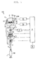
- FIG. 1 is a view illustrating an overall configuration of the winding device 100.
- White arrows in the figure indicate a feeding direction of a spun yarn Y.
- Black arrows in the figure indicate a movable direction of a member (traverse guide 71) constituting the winding device 100.
- the winding device 100 includes a yarn feeder 1.
- a yarn supplying bobbin SB around which the spun yarn (yarn) Y is wound is mounted on the yarn feeder 1.
- the winding device 100 includes a yarn unwinding assisting section 2, a tension applying section 3, a tension detecting section 4, a yarn joining section 5, a defect detecting section 6, a traverse section 7, and a winding section 8 along a feeding direction of the spun yarn Y unwound from the yarn supplying bobbin SB.
- the winding device 100 also includes a control section (hereinafter referred to as "unit control section") 9.
- the yarn unwinding assisting section 2 assists the unwinding of the spun yarn Y wound around the yarn supplying bobbin SB.
- the yarn unwinding assisting section 2 restricts the spun yarn Y unwound from the yarn supplying bobbin SB from spreading by a centrifugal force.
- the tension applying section 3 applies a prescribed tension on the spun yarn Y unwound from the yarn supplying bobbin SB.
- the tension applying section 3 enables high-speed winding of the spun yarn Y by applying the prescribed tension on the spun yarn Y.
- a disc-type tensor and the like may be used for the tension applying section 3.
- the tension detecting section 4 detects the tension applied on the spun yarn Y.
- the tension detecting section 4 can detect the tension applied on the spun yarn Y based on a voltage value that changes in accordance with the tension of the spun yarn Y.
- the unit control section 9 analyses a detection signal from the tension detecting section 4, so that the tension applied on the spun yarn Y is obtained.
- the yarn joining section 5 joins ends of the spun yarn Y.
- the yarn joining section 5 joins the ends of the disconnected spun yarn Y.
- a machine-type splicer device and the like may be used for the yarn joining section 5.
- the defect detecting section 6 detects a defective portion of the spun yarn Y.
- the defect detecting section 6 irradiates the spun yarn Y with a light emitting diode as a light source, and detects the defective portion of the spun yarn Y based on a reflection light quantity from the spun yarn Y.
- an analyzer 61 analyses the detection signal from the defect detecting section 6 to determine the presence or absence of defective portion.
- the defective portion of the spun yarn Y includes a case where foreign substances are contained in the spun yarn Y in addition to abnormalities in which a portion of the spun yarn Y is too thick (thick yarn) or too thin (thin yarn).
- a capacitance sensor and the like may be employed in addition to an optical sensor described above.
- the traverse section 7 traverses the spun yarn Y guided to the package P.
- the traverse section 7 includes a traverse guide 71 and a traverse guide driving unit 72.
- the traverse guide driving unit 72 drives the traverse guide 71 based on a control signal from a traverse guide drive control unit 9a.
- the traverse guide drive control unit 9a transmits a control signal to the traverse guide driving unit 72 based on an instruction from the unit control section 9.
- the traverse guide 71 is an arm member provided with a hooking section adapted to hook the spun yarn Y.
- the traverse guide 71 reciprocates in a rotation shaft direction of a bobbin TB with the spun yarn Y hooked at the hooking section to traverse the spun yarn Y (see black arrows in the figure).
- the traverse guide driving unit 72 is mainly configured by an electric motor.
- the traverse guide driving unit 72 reciprocates the traverse guide 71 by forwardly rotating or reversely rotating a rotation shaft of the electric motor.
- the electric motor constituting the traverse guide driving unit 72 is a servomotor, but may be a stepping motor or the like, for example, and any type of motor may be used.
- the winding section 8 winds the spun yarn Y by rotating the bobbin TB.
- the winding section 8 includes a cradle 81, a roller (hereinafter referred to as "touch roller") 82, and a package driving unit 83.
- the package driving unit 83 rotates the bobbin TB based on a control signal from a package drive control unit 9b.
- the package drive control unit 9b transmits the control signal to the package driving unit 83 based on an instruction from the unit control section 9.
- the cradle 81 includes a bearing for removably clamping the bobbin TB, and rotatably holds the bobbin TB.
- the cradle 81 is configured to be swingable with a swing shaft 84 as a center (see black arrows in FIG. 2 ). Therefore, even if the outer diameter of the package P becomes large corresponding to the winding of the spun yarn Y, the cradle 81 enables the touch roller 82 to press the surface of the package P at a prescribed load.
- the touch roller 82 rotates corresponding to the rotation of the rotating package P.
- the touch roller 82 adjusts the shape of the package P by pressing the surface of the package P.
- the touch roller 82 is a substantially cylindrical rotating body, but may also be a substantially conical (cone-shaped) rotating body, for example, and may be of any shape.
- the package driving unit 83 is mainly configured by an electric motor 83M.
- the package driving unit 83 drives the electric motor 83M to rotate the bobbin TB and the package P formed on the bobbin TB.
- the electric motor 83M constituting the package driving unit 83 is a servomotor, but may also be a stepping motor or the like, for example, and may be of any type.
- the overall configuration of the winding device 100 is as described above.
- the touch roller 82 rotates corresponding to the rotation of the rotating package P.
- the winding device 100 may have a configuration in which the package P rotates corresponding to the rotation of the rotating roller.
- the roller corresponds to a "traverse drum” adapted to rotate the package P while traversing the spun yarn Y by a guiding groove formed on the surface thereof.
- the winding device 100 may employ a traverse drum method.
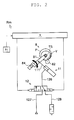
- FIG. 2 is a view illustrating a configuration of the lift mechanism Rm according to a first embodiment. Black arrows in the figure indicate the movable direction of a member (cradle 81) constituting the winding device 100.
- the lift mechanism Rm swings the cradle 81 to bring the package P into contact with the touch roller 82 or to separate the package P from the touch roller 82.
- the lift mechanism Rm is mainly configured by a fluid actuator 11 and an electromagnetic valve 12.
- the fluid actuator 11 swings the cradle 81 when a rod 111 is slidably moved.
- the fluid actuator 11 is configured by a cylinder 112 and a piston 113, in addition to the rod 111.
- the fluid actuator 11 is a single-acting fluid actuator in which the rod 111 slidably moves in one direction by supply of air, but may be a double-acting actuator in which the rod 111 slidably moves in both directions.
- the structure of the fluid actuator 11 is not limited as long as it can swing the cradle 81 to bring the package P into contact with the touch roller 82 or to separate the package P from the touch roller 82.
- the rod 111 is a member adapted to swing the cradle 81.
- a screw portion is formed at an end of the rod 111, and a rod end 114 is screwed with a nut.
- the rod end 114 is a coupling member for coupling the rod 111 and the cradle 81.
- the cylinder 112 is a member for supporting the rod 111 in a slidably moving manner.
- the cylinder 112 is provided with a through-hole 112h, and the rod 111 is inserted to the through-hole 112h.
- a stopper 115 is attached to an end of a cylinder sleeve 21, whereby a movable range of the piston 113 is limited by the stopper 115.
- the piston 113 is a member for slidably moving the rod 111.
- the piston 113 is arranged inside the cylinder 112 and is urged in one direction by a spring 116.
- the piston 113 is formed with a wedge that is formed in a tapered shape to support a steel ball 117 arranged on the outer periphery of the rod 111.
- the electromagnetic valve 12 switches a supply state of air to the fluid actuator 11.
- the electromagnetic valve 12 is configured by a valve body 121, a spool shaft 122, a first solenoid 123, and a second solenoid 124.
- the structure of the electromagnetic valve 12 is not limited as long as the operation to be described later can be realized.
- the spool shaft 122 is slidably provided in the valve body 121.
- the valve body 121 includes a supply and discharge port 121a, which is connected to the fluid actuator 11 via a first air path 126.
- the valve body 121 also includes a supply port 121p, which is connected to a compressor (not illustrated) via a second air path 127, and a discharge port 121r, which is opened to atmosphere via a third air path 128.
- the spool shaft 122 slidablymoves to switch the passage of air. Specifically, the spool shaft 122 slidably moves to switch the passage connected to the first air path 126 to either the second air path 127 or the third air path 128.
- the spool shaft 122 is not urged by the spring or the like, and thus does not slidably move if the first solenoid 123 and the second solenoid 124 are not activated.
- the first solenoid 123 slidably moves the spool shaft 122 to one side (direction of arrow R in FIG. 4 ).
- the first solenoid 123 according to the present embodiment is a so-called single-acting solenoid.
- the first solenoid 123 is adjacent to one end of the spool shaft 122, and slidably moves the spool shaft 122 using the fact that a movable iron core is adsorbed to an excited coil.
- the second solenoid 124 slidably moves the spool shaft 122 to the other side (direction of arrow L in FIG. 4 ).
- the second solenoid 124 according to the present embodiment is a so-called single-acting solenoid.
- the second solenoid 124 is adjacent to the other end of the spool shaft 122, and slidably moves the spool shaft 122 using the fact that a movable iron core is adsorbed to an excited coil.
- the configuration of the lift mechanism Rm according to the first embodiment is as described above.
- the fluid supplied to the fluid actuator 11 is air, but a configuration of supplying operating oil or the like may also be adopted.
- the air is used for the fluid because the air for activating other mechanisms can be commonly used and a simple configuration can be realized.
- the operation mode of the fluid actuator 11 and the electromagnetic valve 12 will be described below, and the technical concept of the present invention and the advantages thereof will be described.
- FIGS. 5A and 5B are views illustrating the operation modes of the fluid actuator 11 and the electromagnetic valve 12.
- FIGS. 6A and 6B are views each illustrating a state in which the package P and the touch roller 82 make contact with or separated from each other.
- the white arrows in the figure indicate the flowing direction of the air.
- the black arrows in the figure indicate the movable direction of the member (cradle 81 or the like) constituting the lift mechanism Rm.
- the unit control section 9 constantly determines whether or not power failure occurred based on the electric signal from a detecting section 91 (see FIG. 1 and FIG. 2 ). When determined that the power failure occurred based on the electric signal from the detecting section 91, the unit control section 9 performs the following control.
- the unit control section 9 transmits a control signal to the electromagnetic valve 12 to activate the first solenoid 123.
- the first solenoid 123 thereby slidably moves the spool shaft 122 to a predetermined position (see black arrow in FIG. 5A ).
- the piston 113 of the fluid actuator 11 then moves by the pressure of air supplied from the electromagnetic valve 12.
- the rod 111 is gripped by the steel ball 117 supported by the wedge of the piston 113 to slidably move with the piston 113 (see black arrow in FIG. 5A ).
- the unit control section 9 slidablymoves the spool shaft 122 to connect the supply and discharge port 121a with the supply port 121p, and to shield the discharge port 121r (see FIG. 5A ).
- the air fed from the compressor is introduced from the second air path 127 to the first air path 126, and then supplied to the fluid actuator 11 (see white arrows in FIG. 5A ).
- the piston 113 then moves by the pressure of the supplied air, and slidably moves the rod 111 held by the steel ball 117 (see black arrow in FIG. 5A ).
- the winding device 100 uses the regenerative electric power generated by the electric motor 83M constituting the package driving unit 83 to apply an operation voltage on the first solenoid 123 of the electromagnetic valve 12. That is, the winding device 100 assumes the electric motor 83M constituting the package driving unit 83 as a power generating section, and activates the first solenoid 123 of the electromagnetic valve 12 by the regenerative electric power generated by the power generating section.
- the winding device 100 can reliably separate the package P and the touch roller 82 from each other even upon power failure (see FIG. 6A ). Therefore, the problem can be prevented in which the spun yarn Y wound into the package P is rubbed by the rotation of the touch roller 82 while the package P rotates by inertia, thus degrading the quality of the spun yarn Y. Furthermore, the power generating motor is not required to be separately arranged since the electric motor 83M adapted to rotate the package P is assumed as the power generating section, whereby a simple configuration can be achieved.
- the unit control section 9 then immediately stops the application of the operation voltage when the lock function of the electromagnetic valve 12 is activated.
- the lock function is realized with a latch structure that maintains the activation state even after the electric power that excites the coil of the first solenoid 123 is stopped or attenuated.
- the latch structure also serving as the lock function of the electromagnetic valve 12, is realized by a permanent magnet (magnet section) 125 adapted to hold the position of the spool shaft 122 even after the electric power that excites the coil of the first solenoid 123 is stopped or attenuated (see FIG. 4 ).
- the latch structure merely needs to be a structure in which the spool shaft 122 does not slidably move if the supply of electric power is stopped, and is not limited to the shown structure.
- the winding device 100 can maintain the state in which the package P and the touch roller 82 are separated from each other without using the regenerative electric power.
- the winding device 100 prevents the cradle 81 from swinging by the stopping or the attenuation of the electric power that excites the coil, and prevents the package P and the touch roller 82 from making contact with each other again. Therefore, the problem can be prevented in which the spun yarn Y wound into the package P is rubbed by the rotation of the touch roller 82, thus degrading the quality of the spun yarn Y.
- the latch structure is realized using the magnetic force of the permanent magnet 125, the package P and the touch roller 82 can be reliably prevented from making contact with each other again with a simple structure.
- the unit control section 9 transmits the control signal to the electromagnetic valve 12 to activate the second solenoid 124 when a considerable time has elapsed in which the rotation of the package P and the touch roller 82 stops, and the power failure is recovered to resume the winding operation.
- the second solenoid 124 thus slidably moves the spool shaft 122 to a predetermined position (see black arrow in FIG. 5B ).
- the piston 113 of the fluid actuator 11 thus moves by the urging force of the spring 116.
- the rod 111 is released from the gripping of the steel ball 117, and slidably moves in the movable direction of the piston 113 by the weight of the package P (see black arrow in FIG. 5B ).
- the unit control section 9 slidably moves the spool shaft 122 to connect the supply and discharge port 121a and the discharge port 121r, and shield the supply port 121p (see FIG. 5B ).
- the air in the cylinder 112 of the fluid actuator 11 is thus guided from the first air path 126 to the third air path 128 and discharged (see white arrows in FIG. 5B ).
- the piston 113 then moves by the urging force of the spring 116, and releases the gripping by the steel ball 117 to slidably move the rod 111 by the weight of the package P (see black arrow in FIG. 5B ).
- the winding device 100 can make the package P and the touch roller 82 into contact with each other after the rotation of the package P and the touch roller 82 is stopped (see FIG. 6B ). Therefore, after the power failure is recovered, the formation of the package P can be immediately resumed.
- the winding device 100 realizes a series of operations with the electromagnetic valve (three port electromagnetic valve) 12 including the supply and discharge port 121a, the supply port 121p, and the discharge port 121r.
- the series of operations can be realized with a four port electromagnetic valve 12X.
- the series of operations can be realized with a five port electromagnetic valve 12Y. Therefore, the technical concept of the present invention has significance in realizing the operations described above, and is not intended to limit the specific configuration of the electromagnetic valve 12 and the like.
Abstract
Description
- The present invention relates to a technique of a winding device adapted to wind a spun yarn to form a package.
- Conventionally, there is known a winding device adapted to wind a spun yarn unwound from a yarn supplying bobbin to form a package (see e.g., Japanese Unexamined Patent Publication No.
2009-286608 2010-13259 - When power failure occurs, the winding device cuts the spun yarn and separates the package and the roller from each other. This prevents the spun yarn having a defective portion from being wound into the package and also prevents degradation in the quality of the spun yarn already wound into the package.
- The reasons for separating the package and the roller from each other will be specifically described below. When power failure occurs, the package and the roller rotate by inertia as the power source is lost. Since the inertia moments of the package and the roller are different, a difference is generated between the peripheral speeds thereof. As described above, since the spun yarn is cut when the power failure occurs, among the spun yarn already wound into the package, the spun yarn wound around the outer periphery is repeatedly rubbed by the rotation of the roller. As a result, degradation in quality such as hairiness of the spun yarn may be caused. Thus, when the power failure occurs, the winding device separates the package and the roller from each other to prevent the quality of the spun yarn from degrading.
- There exists a winding device having a configuration in which the package rotates corresponding to the rotation of the rotating roller (see e.g., Japanese Unexamined Patent Publication No.
2011-105460 - There also exists a winding device having a configuration in which the roller rotates corresponding to the rotation of the rotating package (see e.g., Japanese Unexamined Patent Publication No.
2010-42904 - Even in the winding device having a configuration in which the package rotates corresponding to the rotation of the rotating roller, a similar problem occurs when the inertia moment of the roller is small. That is, if the inertia moment of the roller is small, the regenerative electric power cannot be stably obtained, and the current flow to the electromagnetic valve and the like cannot be continued. In a configuration (configuration using the normal open type electromagnetic valve) in which the package and the roller are separated by an urging force of a spring when the power failure occurs and the current flow to the electromagnetic valve is stopped, the electric power for making the package into contact with the roller is constantly consumed in the situation where the power failure has not occurred (winding operation state), and thus the load of the running cost is large.
- The present invention has been made in view of the above problems, and an object thereof is to provide a winding device capable of maintaining a state in which a package and a roller are separated from each other without using regenerative electric power.
- A winding device of the present invention includes a cradle adapted to rotatably support a package; a roller adapted to rotate while making contact with the package to assist winding of a yarn; and a lift mechanism adapted to swing the cradle to a contacting state in which the package is made into contact with the roller or a separated state in which the package is separated from the roller, wherein the lift mechanism has a lock function of maintaining each of the states without supply of electric power.
- The lift mechanism of the winding device of the present invention includes a fluid actuator adapted to swing the cradle, and an electromagnetic valve adapted to switch a supply state of the fluid to the fluid actuator, and the electromagnetic valve supplies fluid to the fluid actuator to swing the cradle from the contacting state in which the package makes contact with the roller to the separated state in which the package is separated from the roller, and maintains the separated state while holding the supply state of the fluid by the lock function.
- According to the winding device of the present invention, the fluid supplied to the fluid actuator is air.
- The lock function of the winding device of the present invention is realized by a latch structure that maintains each of the states even after electric power for exciting a coil of the electromagnetic valve is stopped or attenuated.
- According to the winding device of the present invention, the latch structure includes a magnet section adapted to maintain each of the states using a magnetic force of a permanent magnet.
- The winding device of the present invention further includes a detecting section adapted to detect power failure, and a power generating section adapted to generate regenerative electric power from the rotation of the package or the roller upon power failure; and a control section adapted to activate the electromagnetic valve by the regenerative electric power generated by the power generating section when the detecting section detects the power failure.
- The power generating section of the winding device of the present invention is an electric motor adapted to rotate the package or the roller.
- The present invention relates to a control method of a winding device, which includes a cradle adapted to rotatably support a package; a roller adapted to rotate while making contact with the package to assist winding of a yarn; and a lift mechanism adapted to swing the cradle to a contacting state in which the package is made into contact with the roller or a separated state in which the package is separated from the roller, wherein the lift mechanism is configured to perform a step of maintaining the contacting state without supply of electric power, and a step of maintaining the separated state without supply of electric power.
- The present invention relates to a control method upon power failure of a winding device, which includes a cradle adapted to rotatably support a package; a roller adapted to rotate while making contact with the package to assist winding of a yarn; a fluid actuator adapted to swing the cradle; an electromagnetic valve adapted to switch a supply state of fluid to the fluid actuator; a detecting section adapted to detect power failure; and a power generating section adapted to generate regenerative electric power from the rotation of the package or the roller upon power failure, wherein the electromagnetic valve is switched when an operation voltage is applied to the electromagnetic valve by the regenerative electric power generated by the power generating section, and the switched state is maintained by a lock function of the electromagnetic valve.
- The present invention has the following effects.
- According to the present invention, the lift mechanism has the lock function of maintaining the contacting state or the separated state without supply of electric power. Thus, a state in which the package and the roller make contact with or separated from each other is maintained without using electric power.
- According to the present invention, the electromagnetic valve supplies fluid to the fluid actuator to swing the cradle from the contacting state in which the package makes contact with the roller to the separated state in which the package is separated from the roller, and then maintains the separated state while holding the supply state of the fluid by the lock function. Thus, a state in which the package and the roller are separated from each other can be maintained without using electric power.
- According to the present invention, the fluid supplied to the fluid actuator is air. Thus, the air for activating other mechanisms can be commonly used, and a simple configuration can be realized.
- According to the present invention, the lock function is realized by a latch structure that maintains each state even after the electric power for exciting a coil of the electromagnetic valve is stopped or attenuated. Accordingly, the cradle is swung by stopping or attenuating the electric power adapted to excite the coil thus preventing the package and the roller from making contact with each other again. Therefore, the problem can be prevented in which the spun yarn wound into the package is rubbed by the rotation of the roller and thus degrading the quality of the spun yarn.
- According to the present invention, the latch structure includes a magnet section adapted to maintain each state using a magnetic force of a permanent magnet. Accordingly, the package and the roller can be reliably prevented from making contact with each other again with a simple structure.
- According to the present invention, the winding device includes a control section adapted to activate the electromagnetic valve by the regenerative electric power generated by the power generating section when the detecting section detects the power failure. Accordingly, the package and the roller can be reliably separated from each other even upon power failure. Therefore, the problem can be prevented in which the spun yarn wound into the package is rubbed by the rotation of the roller and thus degrading the quality of the spun yarn.
- According to the present invention, the power generating section is an electric motor adapted to rotate the package or the roller. Thus, a power generating motor is not required to be separately arranged, and a simple configuration can be realized.
- According to the present invention, the electromagnetic valve is switched when an operation voltage is applied to the electromagnetic valve by the regenerative electric power generated by the power generating section, and the switched state is maintained by the lock function of the electromagnetic valve. Accordingly, a state in which the package and the roller are separated from each other can be maintained without using the regenerative electric power. Furthermore, the cradle is swung by stopping or attenuating the electric power adapted to excite the coil of the solenoid constituting the electromagnetic valve, thus preventing the package and the roller from making contact with each other again. Therefore, the problem can be prevented in which the spun yarn wound into the package is rubbed by the rotation of the roller and thus degrading the quality of the spun yarn.
-
FIG. 1 is a view illustrating an overall configuration of awinding device 100; -
FIG. 2 is a view illustrating a configuration of a lift mechanism Rm according to a first embodiment; -
FIG. 3 is a view illustrating a structure of afluid actuator 11; -
FIG. 4 is a view illustrating a structure of anelectromagnetic valve 12; -
FIGS. 5A and 5B are views illustrating operation modes of thefluid actuator 11 and theelectromagnetic valve 12; -
FIGS. 6A and 6B are views each illustrating a state in which a package P and atouch roller 82 make contact with or separated from each other; and -
FIGS. 7A and 7B are views each illustrating a configuration of the lift mechanism Rm according to another embodiment. - First, a winding
device 100 according to one embodiment of the present invention will be described. -
FIG. 1 is a view illustrating an overall configuration of the windingdevice 100. White arrows in the figure indicate a feeding direction of a spun yarn Y. Black arrows in the figure indicate a movable direction of a member (traverse guide 71) constituting the windingdevice 100. - The winding
device 100 includes ayarn feeder 1. A yarn supplying bobbin SB around which the spun yarn (yarn) Y is wound is mounted on theyarn feeder 1. The windingdevice 100 includes a yarnunwinding assisting section 2, a tension applying section 3, a tension detecting section 4, ayarn joining section 5, a defect detecting section 6, atraverse section 7, and a windingsection 8 along a feeding direction of the spun yarn Y unwound from the yarn supplying bobbin SB. The windingdevice 100 also includes a control section (hereinafter referred to as "unit control section") 9. - The yarn
unwinding assisting section 2 assists the unwinding of the spun yarn Y wound around the yarn supplying bobbin SB. The yarnunwinding assisting section 2 restricts the spun yarn Y unwound from the yarn supplying bobbin SB from spreading by a centrifugal force. - The tension applying section 3 applies a prescribed tension on the spun yarn Y unwound from the yarn supplying bobbin SB. The tension applying section 3 enables high-speed winding of the spun yarn Y by applying the prescribed tension on the spun yarn Y. In addition to a gate-type tensor adapted to apply tension on the spun yarn Y with comb teeth, a disc-type tensor and the like may be used for the tension applying section 3.
- The tension detecting section 4 detects the tension applied on the spun yarn Y. The tension detecting section 4 can detect the tension applied on the spun yarn Y based on a voltage value that changes in accordance with the tension of the spun yarn Y. Specifically, the unit control section 9 analyses a detection signal from the tension detecting section 4, so that the tension applied on the spun yarn Y is obtained.
- The
yarn joining section 5 joins ends of the spun yarn Y. For example, when the spun yarn Y breaks, theyarn joining section 5 joins the ends of the disconnected spun yarn Y. In addition to an air splicer device for joining the ends of the spun yarn Y by a whirling airflow, a machine-type splicer device and the like may be used for theyarn joining section 5. - The defect detecting section 6 detects a defective portion of the spun yarn Y. The defect detecting section 6 irradiates the spun yarn Y with a light emitting diode as a light source, and detects the defective portion of the spun yarn Y based on a reflection light quantity from the spun yarn Y. Specifically, an
analyzer 61 analyses the detection signal from the defect detecting section 6 to determine the presence or absence of defective portion. The defective portion of the spun yarn Y includes a case where foreign substances are contained in the spun yarn Y in addition to abnormalities in which a portion of the spun yarn Y is too thick (thick yarn) or too thin (thin yarn). As the yarn detecting section 6, a capacitance sensor and the like may be employed in addition to an optical sensor described above. - The
traverse section 7 traverses the spun yarn Y guided to the package P. Thetraverse section 7 includes atraverse guide 71 and a traverseguide driving unit 72. The traverseguide driving unit 72 drives thetraverse guide 71 based on a control signal from a traverse guidedrive control unit 9a. The traverse guidedrive control unit 9a transmits a control signal to the traverseguide driving unit 72 based on an instruction from the unit control section 9. - The
traverse guide 71 is an arm member provided with a hooking section adapted to hook the spun yarn Y. Thetraverse guide 71 reciprocates in a rotation shaft direction of a bobbin TB with the spun yarn Y hooked at the hooking section to traverse the spun yarn Y (see black arrows in the figure). - The traverse
guide driving unit 72 is mainly configured by an electric motor. The traverseguide driving unit 72 reciprocates thetraverse guide 71 by forwardly rotating or reversely rotating a rotation shaft of the electric motor. The electric motor constituting the traverseguide driving unit 72 is a servomotor, but may be a stepping motor or the like, for example, and any type of motor may be used. - The winding
section 8 winds the spun yarn Y by rotating the bobbin TB. The windingsection 8 includes acradle 81, a roller (hereinafter referred to as "touch roller") 82, and apackage driving unit 83. Thepackage driving unit 83 rotates the bobbin TB based on a control signal from a packagedrive control unit 9b. The packagedrive control unit 9b transmits the control signal to thepackage driving unit 83 based on an instruction from the unit control section 9. - The
cradle 81 includes a bearing for removably clamping the bobbin TB, and rotatably holds the bobbin TB. Thecradle 81 is configured to be swingable with aswing shaft 84 as a center (see black arrows inFIG. 2 ). Therefore, even if the outer diameter of the package P becomes large corresponding to the winding of the spun yarn Y, thecradle 81 enables thetouch roller 82 to press the surface of the package P at a prescribed load. - The
touch roller 82 rotates corresponding to the rotation of the rotating package P. Thetouch roller 82 adjusts the shape of the package P by pressing the surface of the package P. Thetouch roller 82 is a substantially cylindrical rotating body, but may also be a substantially conical (cone-shaped) rotating body, for example, and may be of any shape. - The
package driving unit 83 is mainly configured by anelectric motor 83M. Thepackage driving unit 83 drives theelectric motor 83M to rotate the bobbin TB and the package P formed on the bobbin TB. Theelectric motor 83M constituting thepackage driving unit 83 is a servomotor, but may also be a stepping motor or the like, for example, and may be of any type. - The overall configuration of the winding
device 100 according to the present embodiment is as described above. As described above, in the windingdevice 100, thetouch roller 82 rotates corresponding to the rotation of the rotating package P. However, the windingdevice 100 may have a configuration in which the package P rotates corresponding to the rotation of the rotating roller. In this case, the roller corresponds to a "traverse drum" adapted to rotate the package P while traversing the spun yarn Y by a guiding groove formed on the surface thereof. In other words, the windingdevice 100 may employ a traverse drum method. - Next, a lift mechanism Rm of the winding
device 100 will be described. -
FIG. 2 is a view illustrating a configuration of the lift mechanism Rm according to a first embodiment. Black arrows in the figure indicate the movable direction of a member (cradle 81) constituting the windingdevice 100. - The lift mechanism Rm swings the
cradle 81 to bring the package P into contact with thetouch roller 82 or to separate the package P from thetouch roller 82. The lift mechanism Rm is mainly configured by afluid actuator 11 and anelectromagnetic valve 12. - The
fluid actuator 11 swings thecradle 81 when arod 111 is slidably moved. As illustrated inFIG. 3 , thefluid actuator 11 is configured by acylinder 112 and apiston 113, in addition to therod 111. Thefluid actuator 11 is a single-acting fluid actuator in which therod 111 slidably moves in one direction by supply of air, but may be a double-acting actuator in which therod 111 slidably moves in both directions. The structure of thefluid actuator 11 is not limited as long as it can swing thecradle 81 to bring the package P into contact with thetouch roller 82 or to separate the package P from thetouch roller 82. - The
rod 111 is a member adapted to swing thecradle 81. A screw portion is formed at an end of therod 111, and arod end 114 is screwed with a nut. Therod end 114 is a coupling member for coupling therod 111 and thecradle 81. - The
cylinder 112 is a member for supporting therod 111 in a slidably moving manner. Thecylinder 112 is provided with a through-hole 112h, and therod 111 is inserted to the through-hole 112h. Astopper 115 is attached to an end of acylinder sleeve 21, whereby a movable range of thepiston 113 is limited by thestopper 115. - The
piston 113 is a member for slidably moving therod 111. Thepiston 113 is arranged inside thecylinder 112 and is urged in one direction by aspring 116. Thepiston 113 is formed with a wedge that is formed in a tapered shape to support asteel ball 117 arranged on the outer periphery of therod 111. - The
electromagnetic valve 12 switches a supply state of air to thefluid actuator 11. As illustrated inFIG. 4 , theelectromagnetic valve 12 is configured by avalve body 121, aspool shaft 122, afirst solenoid 123, and asecond solenoid 124. The structure of theelectromagnetic valve 12 is not limited as long as the operation to be described later can be realized. - The
spool shaft 122 is slidably provided in thevalve body 121. Thevalve body 121 includes a supply anddischarge port 121a, which is connected to thefluid actuator 11 via afirst air path 126. Thevalve body 121 also includes asupply port 121p, which is connected to a compressor (not illustrated) via asecond air path 127, and adischarge port 121r, which is opened to atmosphere via athird air path 128. - The
spool shaft 122 slidablymoves to switch the passage of air. Specifically, thespool shaft 122 slidably moves to switch the passage connected to thefirst air path 126 to either thesecond air path 127 or thethird air path 128. Thespool shaft 122 is not urged by the spring or the like, and thus does not slidably move if thefirst solenoid 123 and thesecond solenoid 124 are not activated. - The
first solenoid 123 slidably moves thespool shaft 122 to one side (direction of arrow R inFIG. 4 ). Thefirst solenoid 123 according to the present embodiment is a so-called single-acting solenoid. Thefirst solenoid 123 is adjacent to one end of thespool shaft 122, and slidably moves thespool shaft 122 using the fact that a movable iron core is adsorbed to an excited coil. - The
second solenoid 124 slidably moves thespool shaft 122 to the other side (direction of arrow L inFIG. 4 ). Thesecond solenoid 124 according to the present embodiment is a so-called single-acting solenoid. Thesecond solenoid 124 is adjacent to the other end of thespool shaft 122, and slidably moves thespool shaft 122 using the fact that a movable iron core is adsorbed to an excited coil. - The configuration of the lift mechanism Rm according to the first embodiment is as described above. In the present winding
device 100, the fluid supplied to thefluid actuator 11 is air, but a configuration of supplying operating oil or the like may also be adopted. The air is used for the fluid because the air for activating other mechanisms can be commonly used and a simple configuration can be realized. The operation mode of thefluid actuator 11 and theelectromagnetic valve 12 will be described below, and the technical concept of the present invention and the advantages thereof will be described. -
FIGS. 5A and 5B are views illustrating the operation modes of thefluid actuator 11 and theelectromagnetic valve 12.FIGS. 6A and 6B are views each illustrating a state in which the package P and thetouch roller 82 make contact with or separated from each other. The white arrows in the figure indicate the flowing direction of the air. The black arrows in the figure indicate the movable direction of the member (cradle 81 or the like) constituting the lift mechanism Rm. - The unit control section 9 constantly determines whether or not power failure occurred based on the electric signal from a detecting section 91 (see
FIG. 1 andFIG. 2 ). When determined that the power failure occurred based on the electric signal from the detectingsection 91, the unit control section 9 performs the following control. - First, the unit control section 9 transmits a control signal to the
electromagnetic valve 12 to activate thefirst solenoid 123. Thefirst solenoid 123 thereby slidably moves thespool shaft 122 to a predetermined position (see black arrow inFIG. 5A ). Thepiston 113 of thefluid actuator 11 then moves by the pressure of air supplied from theelectromagnetic valve 12. As a result, therod 111 is gripped by thesteel ball 117 supported by the wedge of thepiston 113 to slidably move with the piston 113 (see black arrow inFIG. 5A ). - Specifically, the unit control section 9 slidablymoves the
spool shaft 122 to connect the supply anddischarge port 121a with thesupply port 121p, and to shield thedischarge port 121r (seeFIG. 5A ). Thus, the air fed from the compressor is introduced from thesecond air path 127 to thefirst air path 126, and then supplied to the fluid actuator 11 (see white arrows inFIG. 5A ). Thepiston 113 then moves by the pressure of the supplied air, and slidably moves therod 111 held by the steel ball 117 (see black arrow inFIG. 5A ). - The winding
device 100 according to the present embodiment uses the regenerative electric power generated by theelectric motor 83M constituting thepackage driving unit 83 to apply an operation voltage on thefirst solenoid 123 of theelectromagnetic valve 12. That is, the windingdevice 100 assumes theelectric motor 83M constituting thepackage driving unit 83 as a power generating section, and activates thefirst solenoid 123 of theelectromagnetic valve 12 by the regenerative electric power generated by the power generating section. - According to such a configuration, the winding
device 100 can reliably separate the package P and thetouch roller 82 from each other even upon power failure (seeFIG. 6A ). Therefore, the problem can be prevented in which the spun yarn Y wound into the package P is rubbed by the rotation of thetouch roller 82 while the package P rotates by inertia, thus degrading the quality of the spun yarn Y. Furthermore, the power generating motor is not required to be separately arranged since theelectric motor 83M adapted to rotate the package P is assumed as the power generating section, whereby a simple configuration can be achieved. - The unit control section 9 then immediately stops the application of the operation voltage when the lock function of the
electromagnetic valve 12 is activated. The lock function is realized with a latch structure that maintains the activation state even after the electric power that excites the coil of thefirst solenoid 123 is stopped or attenuated. Specifically, the latch structure, also serving as the lock function of theelectromagnetic valve 12, is realized by a permanent magnet (magnet section) 125 adapted to hold the position of thespool shaft 122 even after the electric power that excites the coil of thefirst solenoid 123 is stopped or attenuated (seeFIG. 4 ). The latch structure merely needs to be a structure in which thespool shaft 122 does not slidably move if the supply of electric power is stopped, and is not limited to the shown structure. - According to such a configuration, the winding
device 100 can maintain the state in which the package P and thetouch roller 82 are separated from each other without using the regenerative electric power. The windingdevice 100 prevents thecradle 81 from swinging by the stopping or the attenuation of the electric power that excites the coil, and prevents the package P and thetouch roller 82 from making contact with each other again. Therefore, the problem can be prevented in which the spun yarn Y wound into the package P is rubbed by the rotation of thetouch roller 82, thus degrading the quality of the spun yarn Y. - In the present embodiment, since the latch structure is realized using the magnetic force of the
permanent magnet 125, the package P and thetouch roller 82 can be reliably prevented from making contact with each other again with a simple structure. - Thereafter, the unit control section 9 transmits the control signal to the
electromagnetic valve 12 to activate thesecond solenoid 124 when a considerable time has elapsed in which the rotation of the package P and thetouch roller 82 stops, and the power failure is recovered to resume the winding operation. Thesecond solenoid 124 thus slidably moves thespool shaft 122 to a predetermined position (see black arrow inFIG. 5B ). Thepiston 113 of thefluid actuator 11 thus moves by the urging force of thespring 116. As a result, therod 111 is released from the gripping of thesteel ball 117, and slidably moves in the movable direction of thepiston 113 by the weight of the package P (see black arrow inFIG. 5B ). - Specifically, the unit control section 9 slidably moves the
spool shaft 122 to connect the supply anddischarge port 121a and thedischarge port 121r, and shield thesupply port 121p (seeFIG. 5B ). The air in thecylinder 112 of thefluid actuator 11 is thus guided from thefirst air path 126 to thethird air path 128 and discharged (see white arrows inFIG. 5B ). Thepiston 113 then moves by the urging force of thespring 116, and releases the gripping by thesteel ball 117 to slidably move therod 111 by the weight of the package P (see black arrow inFIG. 5B ). - According to such a configuration, the winding
device 100 can make the package P and thetouch roller 82 into contact with each other after the rotation of the package P and thetouch roller 82 is stopped (seeFIG. 6B ). Therefore, after the power failure is recovered, the formation of the package P can be immediately resumed. - The winding
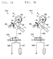
device 100 according to the present embodiment realizes a series of operations with the electromagnetic valve (three port electromagnetic valve) 12 including the supply anddischarge port 121a, thesupply port 121p, and thedischarge port 121r. However, as illustrated inFIG. 7A , for example, the series of operations can be realized with a four portelectromagnetic valve 12X. Furthermore, as illustrated inFIG. 7B , the series of operations can be realized with a five portelectromagnetic valve 12Y. Therefore, the technical concept of the present invention has significance in realizing the operations described above, and is not intended to limit the specific configuration of theelectromagnetic valve 12 and the like.
Claims (9)
- A winding device (100) comprising:a cradle (81) adapted to rotatably support a package (P);a roller (82) adapted to rotate while making contact with the package (P) to assist winding of a yarn; anda lift mechanism (Rm) adapted to swing the cradle (81) to a contacting state in which the package (P) is made into contact with the roller (82) or a separated state in which the package (P) is separated from the roller (82), characterized in thatthe lift mechanism (Rm) has a lock function (125) of maintaining each of the states without supply of electric power.
- The winding device (100) according to claim 1, characterized in thatthe lift mechanism (Rm) includesa fluid actuator (11) adapted to swing the cradle (81), andan electromagnetic valve (12) adapted to switch a supply state of fluid to the fluid actuator (11), andthe electromagnetic valve (12) supplies fluid to the fluid actuator (11) to swing the cradle (81) from the contacting state in which the package (P) makes contact with the roller (82) to the separated state in which the package (P) is separated from the roller (82), and maintains the separated state while holding the supply state of the fluid by the lock function (125).
- The winding device (100) according to claim 2, characterized in that the fluid supplied to the fluid actuator (11) is air.
- The winding device (100) according to claim 2 or 3, characterized in that the lock function (125) is realized by a latch structure (125) that maintains each of the states even after electric power for exciting a coil (124) of the electromagnetic valve (12) is stopped or attenuated.
- The winding device (100) according to claim 4, characterized in that the latch structure (125) includes a magnet section (125) adapted to maintain each of the states using a magnetic force of a permanent magnet.
- The winding device (100) according to any one of claims 2 to 5, characterized by further comprising:a detecting section (91) adapted to detect power failure;a power generating section (83M) adapted to generate regenerative electric power from the rotation of the package (P) or the roller (82) upon power failure; anda control section adapted to activate the electromagnetic valve (12) by the regenerative electric power generated by the power generating section (83M) when the detecting section (91) detects the power failure.
- The winding device (100) according to claim 6, characterized in that the power generating section (83M) is an electric motor (83M) adapted to rotate the package (P) or the roller (82).
- A control method of a winding device (100), with the following steps:a cradle (81) rotatably supports a package (P);a roller (82) rotates while contacting with the package (P) to assist winding of a yarn; anda lift mechanism (Rm) swings the cradle (81) to a contacting state in which the package (P) contacts with the roller (82) or a separated state in which the package (P) is separated from the roller (82), characterized in thatthe lift mechanism (Rm) maintains the contacting state as well as the separated state without supply of electric power.
- A control method according to claim 8 upon power failure, which includesusing a fluid actuator (11) as the lift mechanism (Rm) whereinan electromagnetic valve (12) switches a supply state of fluid to the fluid actuator (11);a detecting section (91) detects power failure; anda power generating section (83M) generates regenerative electric power from the rotation of the package (P) or the roller (82) upon power failure; characterized in thatthe electromagnetic valve (12) switches when an operation voltage is applied to the electromagnetic valve (12) by the regenerative electric power generated by the power generating section (83M), and the switched state is maintained by a lock function (125) of the electromagnetic valve (12).
Applications Claiming Priority (1)
| Application Number | Priority Date | Filing Date | Title |
|---|---|---|---|
| JP2012067681A JP2013199339A (en) | 2012-03-23 | 2012-03-23 | Winding device |
Publications (2)
| Publication Number | Publication Date |
|---|---|
| EP2641859A1 true EP2641859A1 (en) | 2013-09-25 |
| EP2641859B1 EP2641859B1 (en) | 2018-04-11 |
Family
ID=47563257
Family Applications (1)
| Application Number | Title | Priority Date | Filing Date |
|---|---|---|---|
| EP13151729.4A Not-in-force EP2641859B1 (en) | 2012-03-23 | 2013-01-17 | Winding device |
Country Status (3)
| Country | Link |
|---|---|
| EP (1) | EP2641859B1 (en) |
| JP (1) | JP2013199339A (en) |
| CN (1) | CN103318706B (en) |
Cited By (3)
| Publication number | Priority date | Publication date | Assignee | Title |
|---|---|---|---|---|
| EP2862826A1 (en) * | 2013-10-21 | 2015-04-22 | Murata Machinery, Ltd. | Yarn winding machine |
| IT202000002620A1 (en) * | 2020-02-11 | 2021-08-11 | Officine Gaudino S P A | REEL FINISHING DEVICE FOR COMBED SPINNING PROCESSES, EQUIPPED WITH A PERFECTED WICK-WINDING UNIT. |
| EP3865610A1 (en) * | 2020-02-11 | 2021-08-18 | OFFICINE GAUDINO SpA | Finishing device for spinning process provided with a roving-winding assembly |
Families Citing this family (8)
| Publication number | Priority date | Publication date | Assignee | Title |
|---|---|---|---|---|
| CN104073938B (en) * | 2014-07-19 | 2017-03-15 | 无锡市华文机电有限公司 | A kind of broken yarn automatic lifting mechanism |
| CN104773603A (en) * | 2015-03-14 | 2015-07-15 | 张家港欣阳化纤有限公司 | Winding transmission mechanism for chemical fiber production |
| CN106081727A (en) * | 2016-07-26 | 2016-11-09 | 陕西华燕航空仪表有限公司 | Bobbin cradle automatic lifting mechanism |
| CN107128716A (en) * | 2017-06-16 | 2017-09-05 | 太仓鸿海精密机械有限公司 | A kind of coiler device |
| JP6935243B2 (en) * | 2017-06-21 | 2021-09-15 | Tmtマシナリー株式会社 | Thread winder |
| JP2019059601A (en) * | 2017-09-27 | 2019-04-18 | 村田機械株式会社 | Yarn winding machine |
| CH715345A1 (en) * | 2018-09-18 | 2020-03-31 | Ssm Schaerer Schweiter Mettler Ag | Method of pivoting a bobbin in a winding device, and winding device. |
| CN113602907B (en) * | 2021-07-23 | 2022-12-23 | 兔皇羊绒有限公司 | Cashmere yarn coiling mechanism that oils |
Citations (5)
| Publication number | Priority date | Publication date | Assignee | Title |
|---|---|---|---|---|
| US4149679A (en) * | 1978-04-10 | 1979-04-17 | Barber-Colman Company | Package lift device |
| DE4338283A1 (en) * | 1993-11-10 | 1995-05-11 | Schlafhorst & Co W | Textile machine producing cross-wound bobbins |
| EP1106556A2 (en) * | 1999-12-08 | 2001-06-13 | W. SCHLAFHORST AG & CO. | Apparatus for pivoting the bobbin cradle of a textil machine |
| EP1369371A2 (en) * | 2002-06-03 | 2003-12-10 | Murata Kikai Kabushiki Kaisha | Power failure handling system for automatic winder |
| JP2011037608A (en) * | 2009-08-17 | 2011-02-24 | Murata Machinery Ltd | Textile machinery |
-
2012
- 2012-03-23 JP JP2012067681A patent/JP2013199339A/en active Pending
-
2013
- 2013-01-17 EP EP13151729.4A patent/EP2641859B1/en not_active Not-in-force
- 2013-01-24 CN CN201310027535.3A patent/CN103318706B/en not_active Expired - Fee Related
Patent Citations (5)
| Publication number | Priority date | Publication date | Assignee | Title |
|---|---|---|---|---|
| US4149679A (en) * | 1978-04-10 | 1979-04-17 | Barber-Colman Company | Package lift device |
| DE4338283A1 (en) * | 1993-11-10 | 1995-05-11 | Schlafhorst & Co W | Textile machine producing cross-wound bobbins |
| EP1106556A2 (en) * | 1999-12-08 | 2001-06-13 | W. SCHLAFHORST AG & CO. | Apparatus for pivoting the bobbin cradle of a textil machine |
| EP1369371A2 (en) * | 2002-06-03 | 2003-12-10 | Murata Kikai Kabushiki Kaisha | Power failure handling system for automatic winder |
| JP2011037608A (en) * | 2009-08-17 | 2011-02-24 | Murata Machinery Ltd | Textile machinery |
Cited By (3)
| Publication number | Priority date | Publication date | Assignee | Title |
|---|---|---|---|---|
| EP2862826A1 (en) * | 2013-10-21 | 2015-04-22 | Murata Machinery, Ltd. | Yarn winding machine |
| IT202000002620A1 (en) * | 2020-02-11 | 2021-08-11 | Officine Gaudino S P A | REEL FINISHING DEVICE FOR COMBED SPINNING PROCESSES, EQUIPPED WITH A PERFECTED WICK-WINDING UNIT. |
| EP3865610A1 (en) * | 2020-02-11 | 2021-08-18 | OFFICINE GAUDINO SpA | Finishing device for spinning process provided with a roving-winding assembly |
Also Published As
| Publication number | Publication date |
|---|---|
| EP2641859B1 (en) | 2018-04-11 |
| CN103318706B (en) | 2017-04-12 |
| CN103318706A (en) | 2013-09-25 |
| JP2013199339A (en) | 2013-10-03 |
Similar Documents
| Publication | Publication Date | Title |
|---|---|---|
| EP2641859B1 (en) | Winding device | |
| EP2284300B1 (en) | Spinning machine and yarn removing method for removing yarn remaining on yarn accumulating roller | |
| CN101759062B (en) | Yarn winding device and automatic winder | |
| EP2573024B1 (en) | Yarn winding device | |
| CN101074074B (en) | Automatic winder and method for pulling out a yarn end from a winding package | |
| JP2008105755A (en) | Loosened yarn-tightening device incorporating electromagnetic tenser | |
| WO2011040545A1 (en) | Yarn winder | |
| JP2012218922A (en) | Yarn winding apparatus and yarn withdrawal method | |
| EP2105399A2 (en) | Yarn Winding Device and Yarn Winding Method | |
| EP2570377B1 (en) | Traverse guide, winding unit, and winding machine | |
| CN105253703B (en) | Yarn winding machine and yarn winding method | |
| EP2738127A2 (en) | Yarn winding machine and yarn withdrawal method | |
| EP2960196B1 (en) | Yarn winding machine | |
| EP2738128B1 (en) | Yarn winding machine | |
| JP2010037083A (en) | Yarn winding machine and automatic winder | |
| JP2014218314A (en) | Yarn winder | |
| EP2620533B1 (en) | Winding device | |
| CN104555574A (en) | Yarn winding machine | |
| CN109422136B (en) | Yarn winding machine | |
| EP3385205B1 (en) | Yarn winding machine | |
| CN103541057A (en) | Two-for-one twister spindle position driven by single-spindle motor | |
| EP2567920B1 (en) | Yarn winding machine | |
| JP2015174757A (en) | Thread piecing device, take-up unit, and textile machine | |
| JP2009227413A (en) | Yarn winder | |
| JP2008222378A (en) | Yarn winding apparatus |
Legal Events
| Date | Code | Title | Description |
|---|---|---|---|
| PUAI | Public reference made under article 153(3) epc to a published international application that has entered the european phase |
Free format text: ORIGINAL CODE: 0009012 |
|
| AK | Designated contracting states |
Kind code of ref document: A1 Designated state(s): AL AT BE BG CH CY CZ DE DK EE ES FI FR GB GR HR HU IE IS IT LI LT LU LV MC MK MT NL NO PL PT RO RS SE SI SK SM TR |
|
| AX | Request for extension of the european patent |
Extension state: BA ME |
|
| 17P | Request for examination filed |
Effective date: 20140212 |
|
| RBV | Designated contracting states (corrected) |
Designated state(s): AL AT BE BG CH CY CZ DE DK EE ES FI FR GB GR HR HU IE IS IT LI LT LU LV MC MK MT NL NO PL PT RO RS SE SI SK SM TR |
|
| GRAP | Despatch of communication of intention to grant a patent |
Free format text: ORIGINAL CODE: EPIDOSNIGR1 |
|
| STAA | Information on the status of an ep patent application or granted ep patent |
Free format text: STATUS: GRANT OF PATENT IS INTENDED |
|
| INTG | Intention to grant announced |
Effective date: 20180105 |
|
| GRAS | Grant fee paid |
Free format text: ORIGINAL CODE: EPIDOSNIGR3 |
|
| GRAA | (expected) grant |
Free format text: ORIGINAL CODE: 0009210 |
|
| STAA | Information on the status of an ep patent application or granted ep patent |
Free format text: STATUS: THE PATENT HAS BEEN GRANTED |
|
| AK | Designated contracting states |
Kind code of ref document: B1 Designated state(s): AL AT BE BG CH CY CZ DE DK EE ES FI FR GB GR HR HU IE IS IT LI LT LU LV MC MK MT NL NO PL PT RO RS SE SI SK SM TR |
|
| REG | Reference to a national code |
Ref country code: GB Ref legal event code: FG4D |
|
| REG | Reference to a national code |
Ref country code: CH Ref legal event code: EP |
|
| REG | Reference to a national code |
Ref country code: AT Ref legal event code: REF Ref document number: 987803 Country of ref document: AT Kind code of ref document: T Effective date: 20180415 |
|
| REG | Reference to a national code |
Ref country code: IE Ref legal event code: FG4D |
|
| REG | Reference to a national code |
Ref country code: DE Ref legal event code: R096 Ref document number: 602013035608 Country of ref document: DE |
|
| REG | Reference to a national code |
Ref country code: NL Ref legal event code: MP Effective date: 20180411 |
|
| REG | Reference to a national code |
Ref country code: LT Ref legal event code: MG4D |
|
| PG25 | Lapsed in a contracting state [announced via postgrant information from national office to epo] |
Ref country code: NL Free format text: LAPSE BECAUSE OF FAILURE TO SUBMIT A TRANSLATION OF THE DESCRIPTION OR TO PAY THE FEE WITHIN THE PRESCRIBED TIME-LIMIT Effective date: 20180411 |
|
| PG25 | Lapsed in a contracting state [announced via postgrant information from national office to epo] |
Ref country code: BG Free format text: LAPSE BECAUSE OF FAILURE TO SUBMIT A TRANSLATION OF THE DESCRIPTION OR TO PAY THE FEE WITHIN THE PRESCRIBED TIME-LIMIT Effective date: 20180711 Ref country code: NO Free format text: LAPSE BECAUSE OF FAILURE TO SUBMIT A TRANSLATION OF THE DESCRIPTION OR TO PAY THE FEE WITHIN THE PRESCRIBED TIME-LIMIT Effective date: 20180711 Ref country code: LT Free format text: LAPSE BECAUSE OF FAILURE TO SUBMIT A TRANSLATION OF THE DESCRIPTION OR TO PAY THE FEE WITHIN THE PRESCRIBED TIME-LIMIT Effective date: 20180411 Ref country code: FI Free format text: LAPSE BECAUSE OF FAILURE TO SUBMIT A TRANSLATION OF THE DESCRIPTION OR TO PAY THE FEE WITHIN THE PRESCRIBED TIME-LIMIT Effective date: 20180411 Ref country code: SE Free format text: LAPSE BECAUSE OF FAILURE TO SUBMIT A TRANSLATION OF THE DESCRIPTION OR TO PAY THE FEE WITHIN THE PRESCRIBED TIME-LIMIT Effective date: 20180411 Ref country code: PL Free format text: LAPSE BECAUSE OF FAILURE TO SUBMIT A TRANSLATION OF THE DESCRIPTION OR TO PAY THE FEE WITHIN THE PRESCRIBED TIME-LIMIT Effective date: 20180411 Ref country code: ES Free format text: LAPSE BECAUSE OF FAILURE TO SUBMIT A TRANSLATION OF THE DESCRIPTION OR TO PAY THE FEE WITHIN THE PRESCRIBED TIME-LIMIT Effective date: 20180411 Ref country code: AL Free format text: LAPSE BECAUSE OF FAILURE TO SUBMIT A TRANSLATION OF THE DESCRIPTION OR TO PAY THE FEE WITHIN THE PRESCRIBED TIME-LIMIT Effective date: 20180411 |
|
| PG25 | Lapsed in a contracting state [announced via postgrant information from national office to epo] |
Ref country code: LV Free format text: LAPSE BECAUSE OF FAILURE TO SUBMIT A TRANSLATION OF THE DESCRIPTION OR TO PAY THE FEE WITHIN THE PRESCRIBED TIME-LIMIT Effective date: 20180411 Ref country code: RS Free format text: LAPSE BECAUSE OF FAILURE TO SUBMIT A TRANSLATION OF THE DESCRIPTION OR TO PAY THE FEE WITHIN THE PRESCRIBED TIME-LIMIT Effective date: 20180411 Ref country code: HR Free format text: LAPSE BECAUSE OF FAILURE TO SUBMIT A TRANSLATION OF THE DESCRIPTION OR TO PAY THE FEE WITHIN THE PRESCRIBED TIME-LIMIT Effective date: 20180411 Ref country code: GR Free format text: LAPSE BECAUSE OF FAILURE TO SUBMIT A TRANSLATION OF THE DESCRIPTION OR TO PAY THE FEE WITHIN THE PRESCRIBED TIME-LIMIT Effective date: 20180712 |
|
| REG | Reference to a national code |
Ref country code: AT Ref legal event code: MK05 Ref document number: 987803 Country of ref document: AT Kind code of ref document: T Effective date: 20180411 |
|
| PG25 | Lapsed in a contracting state [announced via postgrant information from national office to epo] |
Ref country code: PT Free format text: LAPSE BECAUSE OF FAILURE TO SUBMIT A TRANSLATION OF THE DESCRIPTION OR TO PAY THE FEE WITHIN THE PRESCRIBED TIME-LIMIT Effective date: 20180813 |
|
| REG | Reference to a national code |
Ref country code: DE Ref legal event code: R097 Ref document number: 602013035608 Country of ref document: DE |
|
| PG25 | Lapsed in a contracting state [announced via postgrant information from national office to epo] |
Ref country code: DK Free format text: LAPSE BECAUSE OF FAILURE TO SUBMIT A TRANSLATION OF THE DESCRIPTION OR TO PAY THE FEE WITHIN THE PRESCRIBED TIME-LIMIT Effective date: 20180411 Ref country code: EE Free format text: LAPSE BECAUSE OF FAILURE TO SUBMIT A TRANSLATION OF THE DESCRIPTION OR TO PAY THE FEE WITHIN THE PRESCRIBED TIME-LIMIT Effective date: 20180411 Ref country code: AT Free format text: LAPSE BECAUSE OF FAILURE TO SUBMIT A TRANSLATION OF THE DESCRIPTION OR TO PAY THE FEE WITHIN THE PRESCRIBED TIME-LIMIT Effective date: 20180411 Ref country code: SK Free format text: LAPSE BECAUSE OF FAILURE TO SUBMIT A TRANSLATION OF THE DESCRIPTION OR TO PAY THE FEE WITHIN THE PRESCRIBED TIME-LIMIT Effective date: 20180411 Ref country code: CZ Free format text: LAPSE BECAUSE OF FAILURE TO SUBMIT A TRANSLATION OF THE DESCRIPTION OR TO PAY THE FEE WITHIN THE PRESCRIBED TIME-LIMIT Effective date: 20180411 Ref country code: RO Free format text: LAPSE BECAUSE OF FAILURE TO SUBMIT A TRANSLATION OF THE DESCRIPTION OR TO PAY THE FEE WITHIN THE PRESCRIBED TIME-LIMIT Effective date: 20180411 |
|
| PLBE | No opposition filed within time limit |
Free format text: ORIGINAL CODE: 0009261 |
|
| STAA | Information on the status of an ep patent application or granted ep patent |
Free format text: STATUS: NO OPPOSITION FILED WITHIN TIME LIMIT |
|
| PG25 | Lapsed in a contracting state [announced via postgrant information from national office to epo] |
Ref country code: SM Free format text: LAPSE BECAUSE OF FAILURE TO SUBMIT A TRANSLATION OF THE DESCRIPTION OR TO PAY THE FEE WITHIN THE PRESCRIBED TIME-LIMIT Effective date: 20180411 |
|
| 26N | No opposition filed |
Effective date: 20190114 |
|
| PG25 | Lapsed in a contracting state [announced via postgrant information from national office to epo] |
Ref country code: SI Free format text: LAPSE BECAUSE OF FAILURE TO SUBMIT A TRANSLATION OF THE DESCRIPTION OR TO PAY THE FEE WITHIN THE PRESCRIBED TIME-LIMIT Effective date: 20180411 |
|
| PG25 | Lapsed in a contracting state [announced via postgrant information from national office to epo] |
Ref country code: MC Free format text: LAPSE BECAUSE OF FAILURE TO SUBMIT A TRANSLATION OF THE DESCRIPTION OR TO PAY THE FEE WITHIN THE PRESCRIBED TIME-LIMIT Effective date: 20180411 |
|
| REG | Reference to a national code |
Ref country code: CH Ref legal event code: PL |
|
| GBPC | Gb: european patent ceased through non-payment of renewal fee |
Effective date: 20190117 |
|
| PG25 | Lapsed in a contracting state [announced via postgrant information from national office to epo] |
Ref country code: LU Free format text: LAPSE BECAUSE OF NON-PAYMENT OF DUE FEES Effective date: 20190117 |
|
| REG | Reference to a national code |
Ref country code: BE Ref legal event code: MM Effective date: 20190131 |
|
| REG | Reference to a national code |
Ref country code: IE Ref legal event code: MM4A |
|
| PG25 | Lapsed in a contracting state [announced via postgrant information from national office to epo] |
Ref country code: FR Free format text: LAPSE BECAUSE OF NON-PAYMENT OF DUE FEES Effective date: 20190131 |
|
| PG25 | Lapsed in a contracting state [announced via postgrant information from national office to epo] |
Ref country code: BE Free format text: LAPSE BECAUSE OF NON-PAYMENT OF DUE FEES Effective date: 20190131 |
|
| PG25 | Lapsed in a contracting state [announced via postgrant information from national office to epo] |
Ref country code: LI Free format text: LAPSE BECAUSE OF NON-PAYMENT OF DUE FEES Effective date: 20190131 Ref country code: GB Free format text: LAPSE BECAUSE OF NON-PAYMENT OF DUE FEES Effective date: 20190117 Ref country code: CH Free format text: LAPSE BECAUSE OF NON-PAYMENT OF DUE FEES Effective date: 20190131 |
|
| PG25 | Lapsed in a contracting state [announced via postgrant information from national office to epo] |
Ref country code: IE Free format text: LAPSE BECAUSE OF NON-PAYMENT OF DUE FEES Effective date: 20190117 |
|
| PG25 | Lapsed in a contracting state [announced via postgrant information from national office to epo] |
Ref country code: TR Free format text: LAPSE BECAUSE OF FAILURE TO SUBMIT A TRANSLATION OF THE DESCRIPTION OR TO PAY THE FEE WITHIN THE PRESCRIBED TIME-LIMIT Effective date: 20180411 |
|
| PG25 | Lapsed in a contracting state [announced via postgrant information from national office to epo] |
Ref country code: MT Free format text: LAPSE BECAUSE OF NON-PAYMENT OF DUE FEES Effective date: 20190117 |
|
| PG25 | Lapsed in a contracting state [announced via postgrant information from national office to epo] |
Ref country code: CY Free format text: LAPSE BECAUSE OF FAILURE TO SUBMIT A TRANSLATION OF THE DESCRIPTION OR TO PAY THE FEE WITHIN THE PRESCRIBED TIME-LIMIT Effective date: 20180411 |
|
| PG25 | Lapsed in a contracting state [announced via postgrant information from national office to epo] |
Ref country code: IS Free format text: LAPSE BECAUSE OF FAILURE TO SUBMIT A TRANSLATION OF THE DESCRIPTION OR TO PAY THE FEE WITHIN THE PRESCRIBED TIME-LIMIT Effective date: 20180811 |
|
| PG25 | Lapsed in a contracting state [announced via postgrant information from national office to epo] |
Ref country code: HU Free format text: LAPSE BECAUSE OF FAILURE TO SUBMIT A TRANSLATION OF THE DESCRIPTION OR TO PAY THE FEE WITHIN THE PRESCRIBED TIME-LIMIT; INVALID AB INITIO Effective date: 20130117 |
|
| PGFP | Annual fee paid to national office [announced via postgrant information from national office to epo] |
Ref country code: DE Payment date: 20220119 Year of fee payment: 10 |
|
| PGFP | Annual fee paid to national office [announced via postgrant information from national office to epo] |
Ref country code: IT Payment date: 20220120 Year of fee payment: 10 |
|
| PG25 | Lapsed in a contracting state [announced via postgrant information from national office to epo] |
Ref country code: MK Free format text: LAPSE BECAUSE OF FAILURE TO SUBMIT A TRANSLATION OF THE DESCRIPTION OR TO PAY THE FEE WITHIN THE PRESCRIBED TIME-LIMIT Effective date: 20180411 |
|
| REG | Reference to a national code |
Ref country code: DE Ref legal event code: R119 Ref document number: 602013035608 Country of ref document: DE |
|
| PG25 | Lapsed in a contracting state [announced via postgrant information from national office to epo] |
Ref country code: DE Free format text: LAPSE BECAUSE OF NON-PAYMENT OF DUE FEES Effective date: 20230801 |
|
| PG25 | Lapsed in a contracting state [announced via postgrant information from national office to epo] |
Ref country code: IT Free format text: LAPSE BECAUSE OF NON-PAYMENT OF DUE FEES Effective date: 20230117 |