EP2641855B1 - Apparatus and method for dispensing vehicle balancing weights - Google Patents
Apparatus and method for dispensing vehicle balancing weights Download PDFInfo
- Publication number
- EP2641855B1 EP2641855B1 EP12160441.7A EP12160441A EP2641855B1 EP 2641855 B1 EP2641855 B1 EP 2641855B1 EP 12160441 A EP12160441 A EP 12160441A EP 2641855 B1 EP2641855 B1 EP 2641855B1
- Authority
- EP
- European Patent Office
- Prior art keywords
- belt conveyor
- balancing
- balancing weight
- stack
- feeder
- Prior art date
- Legal status (The legal status is an assumption and is not a legal conclusion. Google has not performed a legal analysis and makes no representation as to the accuracy of the status listed.)
- Not-in-force
Links
- 238000000034 method Methods 0.000 title claims description 10
- 239000003086 colorant Substances 0.000 description 2
- 230000001419 dependent effect Effects 0.000 description 2
- 239000000853 adhesive Substances 0.000 description 1
- 239000002390 adhesive tape Substances 0.000 description 1
- 239000013590 bulk material Substances 0.000 description 1
- 239000011248 coating agent Substances 0.000 description 1
- 238000000576 coating method Methods 0.000 description 1
- 229920000642 polymer Polymers 0.000 description 1
- 239000004810 polytetrafluoroethylene Substances 0.000 description 1
- 229920001343 polytetrafluoroethylene Polymers 0.000 description 1
- 239000007787 solid Substances 0.000 description 1
Images


Classifications
-
- B—PERFORMING OPERATIONS; TRANSPORTING
- B65—CONVEYING; PACKING; STORING; HANDLING THIN OR FILAMENTARY MATERIAL
- B65G—TRANSPORT OR STORAGE DEVICES, e.g. CONVEYORS FOR LOADING OR TIPPING, SHOP CONVEYOR SYSTEMS OR PNEUMATIC TUBE CONVEYORS
- B65G59/00—De-stacking of articles
- B65G59/06—De-stacking from the bottom of the stack
- B65G59/067—De-stacking from the bottom of the stack articles being separated substantially perpendicularly to the axis of the stack
-
- F—MECHANICAL ENGINEERING; LIGHTING; HEATING; WEAPONS; BLASTING
- F16—ENGINEERING ELEMENTS AND UNITS; GENERAL MEASURES FOR PRODUCING AND MAINTAINING EFFECTIVE FUNCTIONING OF MACHINES OR INSTALLATIONS; THERMAL INSULATION IN GENERAL
- F16F—SPRINGS; SHOCK-ABSORBERS; MEANS FOR DAMPING VIBRATION
- F16F15/00—Suppression of vibrations in systems; Means or arrangements for avoiding or reducing out-of-balance forces, e.g. due to motion
- F16F15/32—Correcting- or balancing-weights or equivalent means for balancing rotating bodies, e.g. vehicle wheels
- F16F15/324—Correcting- or balancing-weights or equivalent means for balancing rotating bodies, e.g. vehicle wheels the rotating body being a vehicle wheel
Definitions
- the invention relates to methods and devices for dispensing weights used in vehicle ballasting applications, in particular for dispensing weights used in balancing automobile or other vehicle wheels.
- balancing weights are applied to specific positions of a rim.
- two types of balancing weight are used.
- the first kind is a balancing weight which is attached by a clamp, as disclosed in the European patent EP 1 613 876 B1
- the second kind is fixed by means of a self-adhesive tape, as disclosed in US patent 6,364,421 B1 .
- Both kinds of balancing weights are available in a plurality of sizes, resulting in different weights.
- the correct size of balancing weight is selected and attached to the rim.
- Most balancing weights are supplied as bulk material in boxes, from which the required number of weights is manually taken.
- DE 2745 858 A1 discloses a generic apparatus for dispensing of a bulk components from a cartridge by means of a transport unit and a belt conveyor. Individual components cannot be selected.
- the problem to be solved by the invention is to provide an apparatus and a method for automatic dispensing vehicle balancing weights, dispensing one or a plurality of weights adapted for a required balancing task.
- the weights should be dispensed in such a way that they can be handled by an automatic handling system for applying the weights to a rim.
- At least one cartridge is attached to at least one transport unit for selecting individual weights from the cartridge and moving the selected weights to a belt conveyor in front of the drive unit.
- the at least one cartridge comprises a plurality of sections, wherein each section can hold vehicle balancing weights.
- each cartridge comprises a plurality of trays which may be suited for accommodating different balancing weights.
- the trays may be designed to hold a plurality of different balancing weights. They furthermore may be adapted to specific sizes of balancing weights.
- the trays may have a visible and/or computer readable encoding of at least one of tray size, tray capacity, balancing weight size, quantity of balancing weights in the tray. This may be done by a printed code like a number, a bar code or an electronic code like a transponder or a memory chip which may be contacted by a microcontroller. Such an encoding may also be applied to the at least one cartridge.
- the transport unit has at least one feeder for moving a selected balancing weight from a specific section of one of the trays to the belt conveyor.
- the feeder preferably performs a linear movement and preferably is driven by a linear drive.
- at least one stack lifter is provided for lifting a stack of balancing weights within a section of the trays. This stack lifter is interacting with the feeder.
- the feeder is moving one selected balancing weight to the belt conveyor which is lying on a transport surface from a tray section.
- the balancing weights of the other sections which are not selected either are lifted by stack lifters above the feeder or are sliding on the feeder's surface and remain within their sections, so that they cannot be transported to the belt conveyor.
- the feeder may be operated in two different modes, which may be combined.
- the feeder In a first mode, the feeder is pulled back from the belt conveyor with its end to a position behind the first section closest to the belt conveyor, but before the second section. When the feeder has reached this position, the whole stack of balancing weights in the first section falls down so that the balancing weight at the bottom lies on a transport surface. Now, the feeder may be pushed forward, pushing the bottom balancing weight towards the belt conveyor, until the balancing weight falls on the belt conveyor. Then, the cycle is repeated again. If one section is empty, the procedure is repeated with the next section until all sections are empty. In a different embodiment of the feeder, the feeder may have an opening suited for accommodating one balancing weight.
- the feeder is also pulled back from the belt conveyor until the balancing weight at the bottom of the first section closest to the belt conveyor can fall into this opening. Then, the direction of the feeder is reverted towards the belt conveyor and the balancing weight is transported to the belt conveyor. After all balancing weights of the first section have been transported to the belt conveyor, the feeder moves until it reaches the next section containing balancing weights, which may be the second section, and repeats the same procedure as before. In this way, one section after the other may be emptied. This mode of operation even works without stack lifters. Therefore, according to a simplified embodiment, only a feeder is provided for transporting the balancing weights from the at least one cartridge to the belt conveyor. In this case, the balancing weights are sliding on the surface of the feeder. Therefore, it is further preferred, if the feeder has a surface with a low friction coefficient, which preferably may be achieved by some low friction coating like PTFE.
- a second operating mode there is at least one stack lifter which is interacting with the feeder.
- the stack lifters lift up all stacks in sections which are not the selected one. If, for example, the second section is selected, the stack lifters lift the stack of balancing weights in the first, third, and all consecutive sections up, so that the feeder can be moved without transporting and preferably without touching any one of the balancing weights of these sections. Only the stack lifter of the selected second section remains inactive, therefore allowing the balancing weights of the second stack to fall down to the transport surface after the feeder has been pulled back sufficiently. If the feeder is pushed forward towards the belt conveyor with the selected balancing weight, it has to pass other not selected sections, like the first section in this example. Therefore, the stack lifter of the first section has to be retracted as soon as the selected balancing weight is below the first stack and therefore can bear the load of the stack of balancing weights.
- an additional latch is provided which prevents the balancing weights falling down after a stack lifter has been retracted.
- the latch may be closed locking a stack in its position, until this stack is selected again.
- any section of a tray may be selected for delivering a balancing weight to the belt conveyor.
- all sections of a tray may contain the same size of balancing weights, although it is also possible to use different sizes of balancing weights within different sections of the same tray.
- the sidewalls may be designed to align the balancing weights transported on the belt conveyor.
- the conveyor sidewalls may further be dynamically adjustable by a drive to bring the transported balancing weight into a specific position at the belt conveyor.
- At least one sensor is provided for detecting, whether at least one balancing weight is available in a section of the cartridge. This allows for control of selection of individual weights.
- balancing weights may be selected and delivered with a comparatively high speed. Furthermore, by using multiple cartridges and/or trays in parallel, containing the same type of balancing weight, the speed of deliverance, which may be limited by mass inertia, specifically of the stacks of balancing weights, may be increased. When a section of the cartridge has become empty, it may be continuously refilled during operation without affecting operation. In an alternative embodiment, individual sections, trays, or cartridges may be replaced by refilled sections trays or cartridges. In a further embodiment, at least two sections, trays, or cartridges may be used in parallel to the same belt conveyor, while one is in operation, and the other is being replaced or being refilled.
- a further embodiment of the invention relates to a method for dispensing vehicle balancing weights.
- the method comprises at least the steps of providing balancing weights within a cartridge, preferably comprising at least one tray and further comprising at least one section containing at least one balancing weight.
- the further steps comprise of selecting at least one section and transporting by a transport unit the bottommost balancing weight of the section to a belt conveyor.
- a further step comprises transporting the selected balancing weight by the belt conveyor to at least one chute or tray.
- a selected tray of a plurality of trays may be moved into a position relative to the belt conveyor.
- the balancing weight transported on the belt conveyor is transported into the tray.
- the at least one tray may be fed by a chute; it may be part of a chute or may contain a chute.
- a plurality of trays which is moveable against the belt conveyor is arranged at the end of the belt conveyor, allowing to select at least one of the trays, where an individual balancing weight is delivered. This allows for commissioning of a plurality of balancing weights which are required for a balancing task.
- the cartridge, the trays, or sections thereof are removable or exchangeable.
- a belt conveyor is used to transfer at least one balancing weight from the transport unit to a handling device.
- a handling device may be any automated system like an industrial robot.
- the balancing weights may also be manually handled.
- a controller for controlling the transport unit.
- the controller may receive as an input signal a parameter describing which type of balancing weight is desired or describing a specific section and/or tray and/or cartridge from which a balancing weight is desired. It may further supply a time at which the balancing weight should be delivered.
- the controller is then controlling the transport unit and preferably the belt conveyor in such a way, that the selected balancing weight is received at the end of the belt conveyor at the optionally specified time.
- the controller controls the feeder drives and the stack lift actuators, and the drives of the latches, as well as any further actuators.
- it evaluates signals from sensors, like the sensors for checking the availability of balancing weights in individual sections. It may furthermore evaluate signals from any further sensors.
- it may control the speed of the belt conveyor, and/or the position of trays.
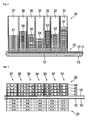
- a belt conveyor 10 is provided for moving balancing weights from a cartridge 20 to a chute or at least one tray or any other device for further processing the balancing weights which may be attached to any one side of the belt conveyor.
- the belt conveyor 10 may have a conveyor pulley 11, and it further may have a belt support 12, which may increase stability on large lengths of the belt.
- the cartridge 20 may comprise of at least one tray 31 to 37. These trays may be filled with balancing weights 51 to 57. In the individual trays, there may be different numbers, different sizes, different types, different colors, and different designs of balancing weights.
- FIG 2 a top view of the dispensing apparatus is shown.
- a first cartridge 20 is shown on one side of the belt conveyor, and a second cartridge 21 at the other side.
- the belt conveyor 10 has conveyor sidewalls 13 and 14, preventing balancing weights from falling off the belt conveyor.
- the cartridges have individual trays 31 to 37 which are further subdivided into sections 41 to 44.
- the cartridges may have a different number of trays and sections as shown herein. Furthermore there may be only one of the cartridges at one side of the belt conveyor. Alternatively there may be a higher number of cartridges.
- FIG. 3 an embodiment is shown in a cross-section in detail.
- belt conveyor 10 is shown with conveyor sidewalls 13 and 14.
- transport units 22 and 23 are shown.
- the transport units On top of the transport units are cartridges 20, 21, showing sections 41 to 44 and containingbalancing weights 51.
- the main part of the transport unit are the feeders 60, 65, which can be moved into directions 62, 67 by means of feeder drives 61, 66.
- a plurality of stack lifters 81 to 84 associated with transport unit 22, and stack lifters 85 to 88 associated with transport unit 23 are provided. These stack lifters may lift the stacks of balancing weights within the sections which are not selected.
- the stack lifters are operated by stack lift actuators 71 to 78, which may for example be solenoids, or electromagnetic drives.
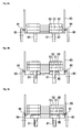
- Figures 4a, 4b and 4c details of the operation of the stack lifter and the feeders in the transport unit are shown.
- Figure 4a shows the starting position, where stack lifters 81 are in an idle position. Balancing weights 51, 52, and 53 are supported on a transport surface 80. The latches 90 are also in an idle position.
- Figure 4b shows the next step of operation, when the stack lifters 81 are moved upwards, thereby lifting the stack of balancing weights one position up. Accordingly, now an open space of the height of at least one balancing weight is below the previously bottommost balancing weight 51.
- balancing weight 58 belonging to a section behind the section shown can be seen.
- this balancing weight is of a smaller size and therefore shorter than the balancing weights 51, 52, 53 in the front section.
- stack lifters 81 are again brought into their idle position.
- latches 91 are brought into operation position, where guides 91 interact with the bottommost balancing weight 51, thus keeping the whole stack in a lifted position and allowing balancing weight 58 to be moved along transport surface 80 by a feeder 60, 65 (not shown herein).
- FIG. 5 shows a top view, in which the individual stack lifters 81, 82, 83, belonging to different sections 41, 42, 43 are shown. They may lift individual balancing weights 51 as previously explained.
- the feeder 60 is fork-shaped to allow movement even when the stack lifters 81, 82, 83 are in their operating position. Generally the number of stack lifters within a section may vary. Dependent of the type of balancing weight, there may be one stack lifter or even three or more stack lifters, which are operated synchronously.
- FIG. 6 A further embodiment with an alternative feeder 60 is shown in Figure 6 .
- the feeder has a cut-out section 68 for holding balancing weight 51. This allows for more precise transport and positioning of balancing weight 51.
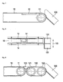
- the belt conveyor may have a belt support 12 and a conveyor pulley 11 at its end. Furthermore, a chute 100 may be provided for transporting the balancing weight from the conveyor pulley.
- a top view of a belt conveyor 10 is shown.
- At the end of the belt conveyor there may further be provided at least one, preferably a plurality of trays 101, 102, which may be moved into the direction 103 for selecting an individual tray into which the balancing weight is transported.
- a second belt conveyor is shown. It comprises a second belt 120, second conveyor pulleys 121, 122 and a support 123.
- This belt conveyor may be controlled independent of the first belt conveyor. Therefore it may be used as a platform for a handling device like an industrial robot to pick up a balancing weight.
- the second belt conveyor brings the balancing weight into the correct position for picking up, which may be dependent on weight size and type.
- the first belt conveyor may be running and transporting the next balancing weight.
- the first belt conveyor may also be used to deliver a balancing weight to a position from which it can be picked up.
Landscapes
- Feeding Of Articles To Conveyors (AREA)
- De-Stacking Of Articles (AREA)
- Intermediate Stations On Conveyors (AREA)
Description
- The invention relates to methods and devices for dispensing weights used in vehicle ballasting applications, in particular for dispensing weights used in balancing automobile or other vehicle wheels.
- In automotive wheel balancing, individual wheel balancing weights are applied to specific positions of a rim. Basically, two types of balancing weight are used. The first kind is a balancing weight which is attached by a clamp, as disclosed in the European patent
EP 1 613 876 B1 , while the second kind is fixed by means of a self-adhesive tape, as disclosed inUS patent 6,364,421 B1 . - Both kinds of balancing weights are available in a plurality of sizes, resulting in different weights. When balancing a vehicle wheel, the correct size of balancing weight is selected and attached to the rim. Most balancing weights are supplied as bulk material in boxes, from which the required number of weights is manually taken.
- This allows for a simple, comparatively cheap supply of balancing weights. The drawback is that the person who is taking the weights from the box may take a wrong weight, and therefore a further step of balancing is required. Furthermore, the process of taking the weights can hardly be automated. Therefore, other solutions as disclosed in
WO 2008/103651 A1 , using a continuous polymer tape, have been developed. This has the drawback that a solid balancing weight is significantly more robust and reliable than these continuous tapes. -
DE 2745 858 A1 discloses a generic apparatus for dispensing of a bulk components from a cartridge by means of a transport unit and a belt conveyor. Individual components cannot be selected. - The problem to be solved by the invention is to provide an apparatus and a method for automatic dispensing vehicle balancing weights, dispensing one or a plurality of weights adapted for a required balancing task. The weights should be dispensed in such a way that they can be handled by an automatic handling system for applying the weights to a rim.
- At least one cartridge is attached to at least one transport unit for selecting individual weights from the cartridge and moving the selected weights to a belt conveyor in front of the drive unit. The at least one cartridge comprises a plurality of sections, wherein each section can hold vehicle balancing weights. Furthermore, it is preferred, if each cartridge comprises a plurality of trays which may be suited for accommodating different balancing weights. The trays may be designed to hold a plurality of different balancing weights. They furthermore may be adapted to specific sizes of balancing weights. The trays may have a visible and/or computer readable encoding of at least one of tray size, tray capacity, balancing weight size, quantity of balancing weights in the tray. This may be done by a printed code like a number, a bar code or an electronic code like a transponder or a memory chip which may be contacted by a microcontroller. Such an encoding may also be applied to the at least one cartridge.
- The transport unit has at least one feeder for moving a selected balancing weight from a specific section of one of the trays to the belt conveyor. The feeder preferably performs a linear movement and preferably is driven by a linear drive. Furthermore, at least one stack lifter is provided for lifting a stack of balancing weights within a section of the trays. This stack lifter is interacting with the feeder. The feeder is moving one selected balancing weight to the belt conveyor which is lying on a transport surface from a tray section. The balancing weights of the other sections which are not selected either are lifted by stack lifters above the feeder or are sliding on the feeder's surface and remain within their sections, so that they cannot be transported to the belt conveyor. The feeder may be operated in two different modes, which may be combined. In a first mode, the feeder is pulled back from the belt conveyor with its end to a position behind the first section closest to the belt conveyor, but before the second section. When the feeder has reached this position, the whole stack of balancing weights in the first section falls down so that the balancing weight at the bottom lies on a transport surface. Now, the feeder may be pushed forward, pushing the bottom balancing weight towards the belt conveyor, until the balancing weight falls on the belt conveyor. Then, the cycle is repeated again. If one section is empty, the procedure is repeated with the next section until all sections are empty. In a different embodiment of the feeder, the feeder may have an opening suited for accommodating one balancing weight. In this embodiment, the feeder is also pulled back from the belt conveyor until the balancing weight at the bottom of the first section closest to the belt conveyor can fall into this opening. Then, the direction of the feeder is reverted towards the belt conveyor and the balancing weight is transported to the belt conveyor. After all balancing weights of the first section have been transported to the belt conveyor, the feeder moves until it reaches the next section containing balancing weights, which may be the second section, and repeats the same procedure as before. In this way, one section after the other may be emptied. This mode of operation even works without stack lifters. Therefore, according to a simplified embodiment, only a feeder is provided for transporting the balancing weights from the at least one cartridge to the belt conveyor. In this case, the balancing weights are sliding on the surface of the feeder. Therefore, it is further preferred, if the feeder has a surface with a low friction coefficient, which preferably may be achieved by some low friction coating like PTFE.
- In a second operating mode, there is at least one stack lifter which is interacting with the feeder. Generally, the stack lifters lift up all stacks in sections which are not the selected one. If, for example, the second section is selected, the stack lifters lift the stack of balancing weights in the first, third, and all consecutive sections up, so that the feeder can be moved without transporting and preferably without touching any one of the balancing weights of these sections. Only the stack lifter of the selected second section remains inactive, therefore allowing the balancing weights of the second stack to fall down to the transport surface after the feeder has been pulled back sufficiently. If the feeder is pushed forward towards the belt conveyor with the selected balancing weight, it has to pass other not selected sections, like the first section in this example. Therefore, the stack lifter of the first section has to be retracted as soon as the selected balancing weight is below the first stack and therefore can bear the load of the stack of balancing weights.
- In a further embodiment, an additional latch is provided which prevents the balancing weights falling down after a stack lifter has been retracted. The latch may be closed locking a stack in its position, until this stack is selected again.
- As disclosed, any section of a tray may be selected for delivering a balancing weight to the belt conveyor. In a first embodiment, all sections of a tray may contain the same size of balancing weights, although it is also possible to use different sizes of balancing weights within different sections of the same tray. Furthermore, it may be possible to use different sections with different colors and/or design of balancing weights, preferably of the same size.
- In a further preferred embodiment, there is at least one conveyor sidewall at at least one side of the belt conveyor, preventing balancing weights on the belt conveyor to leave the belt conveyor. Furthermore, the sidewalls may be designed to align the balancing weights transported on the belt conveyor. The conveyor sidewalls may further be dynamically adjustable by a drive to bring the transported balancing weight into a specific position at the belt conveyor.
- In a further embodiment, at least one sensor is provided for detecting, whether at least one balancing weight is available in a section of the cartridge. This allows for control of selection of individual weights.
- By using the apparatus disclosed herein, balancing weights may be selected and delivered with a comparatively high speed. Furthermore, by using multiple cartridges and/or trays in parallel, containing the same type of balancing weight, the speed of deliverance, which may be limited by mass inertia, specifically of the stacks of balancing weights, may be increased. When a section of the cartridge has become empty, it may be continuously refilled during operation without affecting operation. In an alternative embodiment, individual sections, trays, or cartridges may be replaced by refilled sections trays or cartridges. In a further embodiment, at least two sections, trays, or cartridges may be used in parallel to the same belt conveyor, while one is in operation, and the other is being replaced or being refilled.
- A further embodiment of the invention relates to a method for dispensing vehicle balancing weights. The method comprises at least the steps of providing balancing weights within a cartridge, preferably comprising at least one tray and further comprising at least one section containing at least one balancing weight. The further steps comprise of selecting at least one section and transporting by a transport unit the bottommost balancing weight of the section to a belt conveyor. A further step comprises transporting the selected balancing weight by the belt conveyor to at least one chute or tray. In a further optional step, a selected tray of a plurality of trays may be moved into a position relative to the belt conveyor. In a next step the balancing weight transported on the belt conveyor is transported into the tray.
- In a further embodiment of the invention, there may be at least one tray at the end of the belt conveyor. The at least one tray may be fed by a chute; it may be part of a chute or may contain a chute. In a preferred embodiment, a plurality of trays which is moveable against the belt conveyor is arranged at the end of the belt conveyor, allowing to select at least one of the trays, where an individual balancing weight is delivered. This allows for commissioning of a plurality of balancing weights which are required for a balancing task.
- In a further embodiment, the cartridge, the trays, or sections thereof are removable or exchangeable.
- Preferably, a belt conveyor is used to transfer at least one balancing weight from the transport unit to a handling device. This may be any automated system like an industrial robot. In specific cases, the balancing weights may also be manually handled. There may be any intermediate device like a chute or trays.
- In a further embodiment, a controller is provided for controlling the transport unit. The controller may receive as an input signal a parameter describing which type of balancing weight is desired or describing a specific section and/or tray and/or cartridge from which a balancing weight is desired. It may further supply a time at which the balancing weight should be delivered. The controller is then controlling the transport unit and preferably the belt conveyor in such a way, that the selected balancing weight is received at the end of the belt conveyor at the optionally specified time. Most preferably, the controller controls the feeder drives and the stack lift actuators, and the drives of the latches, as well as any further actuators. Furthermore, it evaluates signals from sensors, like the sensors for checking the availability of balancing weights in individual sections. It may furthermore evaluate signals from any further sensors. In addition, it may control the speed of the belt conveyor, and/or the position of trays.
- It is obvious that the embodiments disclosed herein are applicable to a broad variety of balancing weights like balancing weights which may be held by a clamp or self-adhesive balancing weights.
- In the following the invention will be described by way of example, without limitation of the general inventive concept, on examples of embodiment with reference to the drawings.
-
Figure 1 shows an apparatus for dispensing vehicle balancing weights. -
Figure 2 shows the apparatus in a top view. -
Figure 3 shows a cross-section of the apparatus. -
Figure 4 shows a front view of the transport unit. -
Figure 5 shows a top view of the feeder. -
Figure 6 shows a different feeder. -
Figure 7 shows the belt conveyor with a tube. -
Figure 8 shows the belt conveyor with trays. -
Figure 9 shows a second belt conveyor. - In
Figure 1 , a preferred embodiment according to the invention is shown. Abelt conveyor 10 is provided for moving balancing weights from acartridge 20 to a chute or at least one tray or any other device for further processing the balancing weights which may be attached to any one side of the belt conveyor. Thebelt conveyor 10 may have aconveyor pulley 11, and it further may have abelt support 12, which may increase stability on large lengths of the belt. Below thecartridge 20, there is at least onetransport unit 22 for transporting balancing weights from the cartridge to the belt conveyor. Thecartridge 20 may comprise of at least onetray 31 to 37. These trays may be filled with balancingweights 51 to 57. In the individual trays, there may be different numbers, different sizes, different types, different colors, and different designs of balancing weights. - In
Figure 2 , a top view of the dispensing apparatus is shown. Here, afirst cartridge 20 is shown on one side of the belt conveyor, and asecond cartridge 21 at the other side. Thebelt conveyor 10 hasconveyor sidewalls individual trays 31 to 37 which are further subdivided intosections 41 to 44. The cartridges may have a different number of trays and sections as shown herein. Furthermore there may be only one of the cartridges at one side of the belt conveyor. Alternatively there may be a higher number of cartridges. - In
Figure 3 , an embodiment is shown in a cross-section in detail. In the center,belt conveyor 10 is shown withconveyor sidewalls transport units cartridges sections 41 to 44 andcontainingbalancing weights 51. The main part of the transport unit are thefeeders directions stack lifters 81 to 84 associated withtransport unit 22, and stacklifters 85 to 88 associated withtransport unit 23 are provided. These stack lifters may lift the stacks of balancing weights within the sections which are not selected. The stack lifters are operated by stack lift actuators 71 to 78, which may for example be solenoids, or electromagnetic drives. - In
Figures 4a, 4b and 4c , details of the operation of the stack lifter and the feeders in the transport unit are shown.Figure 4a shows the starting position, where stack lifters 81 are in an idle position. Balancingweights transport surface 80. Thelatches 90 are also in an idle position.Figure 4b shows the next step of operation, when thestack lifters 81 are moved upwards, thereby lifting the stack of balancing weights one position up. Accordingly, now an open space of the height of at least one balancing weight is below the previously bottommost balancingweight 51. In this Figure, balancingweight 58 belonging to a section behind the section shown can be seen. In an exemplary embodiment, this balancing weight is of a smaller size and therefore shorter than the balancingweights Figure 4c . Here,stack lifters 81 are again brought into their idle position. To prevent the stack of balancingweights transport surface 80, latches 91 are brought into operation position, where guides 91 interact with the bottommost balancingweight 51, thus keeping the whole stack in a lifted position and allowing balancingweight 58 to be moved alongtransport surface 80 by afeeder 60, 65 (not shown herein). - Further details of the operation of the feeder are shown in
Figure 5 . It shows a top view, in which theindividual stack lifters different sections individual balancing weights 51 as previously explained. Preferably, thefeeder 60 is fork-shaped to allow movement even when thestack lifters - A further embodiment with an
alternative feeder 60 is shown inFigure 6 . Herein, the feeder has a cut-outsection 68 for holding balancingweight 51. This allows for more precise transport and positioning of balancingweight 51. - In
Figure 7 , a side view of the belt conveyor is shown. The belt conveyor may have abelt support 12 and aconveyor pulley 11 at its end. Furthermore, achute 100 may be provided for transporting the balancing weight from the conveyor pulley. - In
Figure 8 , a top view of abelt conveyor 10 is shown. Preferably, there are at least one or twosidewalls balancing weights 51 during transport by the belt conveyor. At the end of the belt conveyor, there may further be provided at least one, preferably a plurality oftrays direction 103 for selecting an individual tray into which the balancing weight is transported. - In
Figure 9 a second belt conveyor is shown. It comprises asecond belt 120, second conveyor pulleys 121, 122 and asupport 123. This belt conveyor may be controlled independent of the first belt conveyor. Therefore it may be used as a platform for a handling device like an industrial robot to pick up a balancing weight. Here the second belt conveyor brings the balancing weight into the correct position for picking up, which may be dependent on weight size and type. At the same time the first belt conveyor may be running and transporting the next balancing weight. Of course the first belt conveyor may also be used to deliver a balancing weight to a position from which it can be picked up. By using two conveyors, transport over a longer distance between the cartridges, which also takes time can be separated from picking up and results in a significant increase of delivering speed and throughput. -
- 10
- belt conveyor
- 11
- conveyor pulley
- 12
- belt support
- 13, 14
- conveyor sidewalls
- 20, 21
- cartridge
- 22, 23
- transport unit
- 31 - 37
- trays
- 41 - 44
- sections
- 51 - 57
- balancing weights
- 60, 65
- feeder
- 61, 66
- feeder drive
- 62, 67
- feeder movement direction
- 68
- cut-out section
- 71 - 78
- stack lifter actuators
- 80
- transport surface
- 81 - 88
- stack lifters
- 90
- latch
- 91
- guide
- 100
- chute, tray
- 101, 102
- trays
- 103
- direction of movement of trays
- 111 - 118
- sensors
- 120
- second belt
- 121, 122
- second conveyor pulleys
- 123
- support
Claims (11)
- Apparatus for dispensing vehicle balancing weights comprising- at least one cartridge (20, 21) adapted to store at least one balancing weight (51 to 57), the cartridge further comprising a plurality of sections (41 to 45);- a belt conveyor for transporting at least one balancing weight to a handling device;- at least one transport unit (22, 23), located below the at least one cartridge, for transporting a balancing weight from a selected section to the belt conveyor (10),
the at least one transport unit comprises a feeder for moving the balancing weight from the selected section and pushing it on the belt conveyor,
the feeder performing a linear movement into a direction to the belt conveyor,- a stack lifter (81 to 88) for each section of the at least one cartridge for lifting a stack of balancing weights within the respective sections between the selected section and the belt conveyor to allow the feeder to shift the balancing weight towards the belt conveyor under the lifted stack of balancing weights. - Apparatus according to any one of the previous claims,
characterized in that
the at least one feeder (60, 65) is fork-shaped and has cut-outs for the stack lifters 81 to 88. - Apparatus according to any one of the previous claims,
characterized in that
the at least one feeder (60, 65) has a cut-out section for accommodating at least one balancing weight. - Apparatus according to any one of the previous claims,
characterized in that
at least one sidewall (13, 14) is provided at the sides of the belt conveyor (10). - Apparatus according to any one of the previous claims,
characterized in that
at least one cartridge (20, 21) and at least one transport unit (22, 23) is provided to each of the both sides of the belt conveyor. - Apparatus according to claims 4 or 5,
characterized in that
at least one of the conveyor sidewalls (13, 14) is adjustable for aligning at least one balancing weight being transported by the belt conveyor. - Apparatus according to any one of the previous claims,
characterized in that
a chute is provided at at least one end of the belt conveyor. - Apparatus according to any one of the previous claims,
characterized in that
at least one tray (101, 102) is provided at one end of the belt conveyor. - Apparatus according to claim 8,
characterized in that
the at least one tray (101, 102) is moveable, so that any selected tray may be loaded by the belt conveyor. - Method for dispensing vehicle balancing weights, comprising the steps of- providing a cartridge (20, 21) with a plurality of sections containing at least one stack of balancing weights (51 to 57);- selecting a section of the cartridge from which a balancing weight should be taken;- lifting the stack of balancing weights in sections between the selected section and a belt conveyor for transporting at least one balancing weight to a handling device;- pushing the bottommost balancing weight of the selected section under the sections with previously lifted balancing weights onto the belt conveyor.
- Method according to claim 10, further comprising the step of transporting a balancing weight by the belt conveyor to a handling device.
Priority Applications (5)
| Application Number | Priority Date | Filing Date | Title |
|---|---|---|---|
| ES12160441.7T ES2487220T3 (en) | 2012-03-20 | 2012-03-20 | Apparatus and procedure for balancing weights of a vehicle |
| EP12160441.7A EP2641855B1 (en) | 2012-03-20 | 2012-03-20 | Apparatus and method for dispensing vehicle balancing weights |
| JP2015500832A JP5832692B2 (en) | 2012-03-20 | 2013-03-08 | Apparatus and method for distributing balance weights for vehicles |
| PCT/EP2013/054740 WO2013139626A1 (en) | 2012-03-20 | 2013-03-08 | Apparatus and method for dispensing vehicle balancing weights |
| US14/488,690 US9555981B2 (en) | 2012-03-20 | 2014-09-17 | Apparatus and method for dispensing vehicle balancing weights |
Applications Claiming Priority (1)
| Application Number | Priority Date | Filing Date | Title |
|---|---|---|---|
| EP12160441.7A EP2641855B1 (en) | 2012-03-20 | 2012-03-20 | Apparatus and method for dispensing vehicle balancing weights |
Publications (2)
| Publication Number | Publication Date |
|---|---|
| EP2641855A1 EP2641855A1 (en) | 2013-09-25 |
| EP2641855B1 true EP2641855B1 (en) | 2014-05-14 |
Family
ID=47844320
Family Applications (1)
| Application Number | Title | Priority Date | Filing Date |
|---|---|---|---|
| EP12160441.7A Not-in-force EP2641855B1 (en) | 2012-03-20 | 2012-03-20 | Apparatus and method for dispensing vehicle balancing weights |
Country Status (5)
| Country | Link |
|---|---|
| US (1) | US9555981B2 (en) |
| EP (1) | EP2641855B1 (en) |
| JP (1) | JP5832692B2 (en) |
| ES (1) | ES2487220T3 (en) |
| WO (1) | WO2013139626A1 (en) |
Families Citing this family (12)
| Publication number | Priority date | Publication date | Assignee | Title |
|---|---|---|---|---|
| EP2642156B1 (en) * | 2012-03-20 | 2017-06-14 | WEGMANN automotive GmbH & Co. KG | Tray assembly for balancing weights |
| WO2015134426A1 (en) | 2014-03-03 | 2015-09-11 | 3M Innovative Properties Company | Wheel balancing weights, and methods and devices for using same |
| JP6730003B2 (en) * | 2014-03-27 | 2020-07-29 | 積水化学工業株式会社 | Flame-retardant urethane resin composition |
| CN105083830A (en) * | 2015-09-02 | 2015-11-25 | 苏州艾隆科技股份有限公司 | Medicine discharging mechanism |
| CN108351271B (en) * | 2015-10-05 | 2021-06-04 | 3M创新有限公司 | Apparatus and method for automatically applying weight material to a wheel |
| EP3312449B8 (en) * | 2016-10-24 | 2019-05-22 | WEGMANN automotive GmbH | Automatic dispenser for balancing weights |
| JP2019537887A (en) * | 2016-11-07 | 2019-12-26 | エーナイン・ドット・コム インコーポレイテッドA9.com, Inc. | System and method for enhanced mesh networking |
| US11167423B1 (en) * | 2019-02-18 | 2021-11-09 | Amazon Technologies, Inc. | End of arm tool capable of ejecting totes |
| ES2928368T3 (en) * | 2019-08-23 | 2022-11-17 | Jungheinrich Ag | Stacked Storage Arrangement |
| CN110937362A (en) * | 2019-12-26 | 2020-03-31 | 江西宏幸智能制造科技有限公司 | Automatic batch feeder for metal industrial furnace |
| CN112476946B (en) * | 2020-09-23 | 2022-06-21 | 宁波韵升粘结磁体有限公司 | A method for automatic injection molding of magnetized magnetic steel |
| CN117755796B (en) * | 2024-02-22 | 2024-05-14 | 苏州锐杰微科技集团有限公司 | Feeding system for chip production and working method thereof |
Family Cites Families (34)
| Publication number | Priority date | Publication date | Assignee | Title |
|---|---|---|---|---|
| US427509A (en) * | 1890-05-06 | Spool-thread cabinet | ||
| US3756363A (en) * | 1971-09-15 | 1973-09-04 | Ardac Inc | Change dispensing apparatus |
| US3933255A (en) * | 1973-12-06 | 1976-01-20 | Bemis Company, Inc. | Case magazine and feed apparatus |
| IT1017779B (en) * | 1974-07-31 | 1977-08-10 | Sitma Soc Italiana Macchine Au | AUTOMATIC EQUIPMENT FOR FEEDING AN OBJECT FROM A STORAGE TANK TO A CONVEYOR |
| DE2745858A1 (en) * | 1977-10-12 | 1979-04-19 | Artur Hethey | Workpiece magazine with automatic feed - has sides which slide upwards with delivery by thruster and holding plate |
| JPS5943313Y2 (en) * | 1979-09-06 | 1984-12-21 | 松下電器産業株式会社 | Plate member supply device |
| JPS5643836A (en) | 1979-09-17 | 1981-04-22 | Nec Corp | Repeater |
| FR2480101A1 (en) * | 1980-04-10 | 1981-10-16 | Guigan Jean | DEVICE FOR AUTOMATICALLY STORING AND DISPENSING OBJECTS |
| JPS579636A (en) * | 1980-06-13 | 1982-01-19 | Seiko Epson Corp | Material feeder with stacked magazines |
| CH650985A5 (en) * | 1981-05-12 | 1985-08-30 | Sig Schweiz Industrieges | METHOD FOR REMOVING AT LEAST ONE FLAT OBJECT FROM A STACK, AND APPLYING THE METHOD. |
| DE8313868U1 (en) * | 1983-05-10 | 1986-12-04 | Siemens AG, 1000 Berlin und 8000 München | Storage magazine for stackable goods |
| US4844686A (en) * | 1986-06-02 | 1989-07-04 | Colmac, Inc. | Collating apparatus |
| JPH0364931A (en) | 1989-08-03 | 1991-03-20 | Fuji Electric Co Ltd | Mos type semiconductor device |
| JPH0739874Y2 (en) * | 1989-10-25 | 1995-09-13 | 株式会社ロゼフテクノロジー | Magazine loading device |
| US5065897A (en) * | 1990-10-25 | 1991-11-19 | Smith Robert D | Universal dispensing apparatus for stacked articles |
| JPH07282347A (en) * | 1994-04-11 | 1995-10-27 | Shibaura Eng Works Co Ltd | vending machine |
| JPH07315574A (en) * | 1994-05-26 | 1995-12-05 | Okura Yusoki Co Ltd | Picking device |
| US5480280A (en) * | 1994-10-21 | 1996-01-02 | Conveying Industries, Inc. | Method and apparatus for dispensing pallets |
| US5645392A (en) * | 1995-09-08 | 1997-07-08 | Micromatic Operations, Inc. | Dunnage handling system |
| US5893701A (en) * | 1996-06-13 | 1999-04-13 | Food Machinery Sales, Inc. | Method and apparatus for forming groups of work products |
| US6089819A (en) * | 1997-08-18 | 2000-07-18 | Hk Systems, Inc. | Method and apparatus for palletizing and depalletizing layers of articles on stackable pallets |
| US6364421B1 (en) | 1998-12-09 | 2002-04-02 | Perfect Equipment Company Llc | Wheel balancing weights |
| JP2002012324A (en) * | 2000-06-28 | 2002-01-15 | Seibu Electric & Mach Co Ltd | Article handling equipment |
| KR100890465B1 (en) * | 2001-09-10 | 2009-03-27 | 가부시키가이샤 유야마 세이사쿠쇼 | Medicine feed apparatus |
| JP2003164932A (en) * | 2001-11-29 | 2003-06-10 | Shinmei Ind Co Ltd | Work stocking device and work aligning and loading device |
| KR200282447Y1 (en) * | 2002-04-01 | 2002-07-19 | 주식회사에이멕스 | Vending Machine for Kimchi |
| FR2838114B1 (en) * | 2002-04-08 | 2004-10-29 | Jean Claude Gouy | ASSEMBLY FOR STORING, SORTING AND PREPARING ARTICLES |
| WO2004090495A2 (en) | 2003-04-11 | 2004-10-21 | Franken Industrie Werke Ernst Stenz Gmbh & Co.Kg | Balancing weight for vehicle wheels, comprising a concavely or convexly curved contact face, and method for the production thereof |
| CN1950279B (en) * | 2004-04-30 | 2011-04-13 | 株式会社汤山制作所 | Medicine tray supply device |
| JP2006335514A (en) * | 2005-06-01 | 2006-12-14 | Shibuya Kogyo Co Ltd | Container conveying device |
| WO2008103651A1 (en) | 2007-02-19 | 2008-08-28 | 3M Innovative Properties Company | Apparatus and method for dispensing vehicle ballasting weights |
| JP5253771B2 (en) * | 2007-07-25 | 2013-07-31 | 株式会社東芝 | Tray holding device |
| KR100884329B1 (en) * | 2008-06-05 | 2009-02-18 | 안지영 | Package Product Transfer Device |
| EP2179656A1 (en) * | 2008-10-24 | 2010-04-28 | Cremona Inoxidable S.r.l. | System for stacking and unstacking mold units |
-
2012
- 2012-03-20 ES ES12160441.7T patent/ES2487220T3/en active Active
- 2012-03-20 EP EP12160441.7A patent/EP2641855B1/en not_active Not-in-force
-
2013
- 2013-03-08 WO PCT/EP2013/054740 patent/WO2013139626A1/en not_active Ceased
- 2013-03-08 JP JP2015500832A patent/JP5832692B2/en not_active Expired - Fee Related
-
2014
- 2014-09-17 US US14/488,690 patent/US9555981B2/en not_active Expired - Fee Related
Also Published As
| Publication number | Publication date |
|---|---|
| US9555981B2 (en) | 2017-01-31 |
| WO2013139626A1 (en) | 2013-09-26 |
| US20150010380A1 (en) | 2015-01-08 |
| EP2641855A1 (en) | 2013-09-25 |
| JP2015516345A (en) | 2015-06-11 |
| JP5832692B2 (en) | 2015-12-16 |
| ES2487220T3 (en) | 2014-08-20 |
Similar Documents
| Publication | Publication Date | Title |
|---|---|---|
| US9555981B2 (en) | Apparatus and method for dispensing vehicle balancing weights | |
| US12006168B2 (en) | Palletizer-depalletizer system for distribution facilities | |
| DK2018528T3 (en) | Method and system for batch formation of objects | |
| US6971833B1 (en) | Order picking system | |
| CN110015528B (en) | Delivery warehouse and method for receiving, temporarily storing and dispensing deliveries | |
| US20120213617A1 (en) | Angular load support as well as storage and order-picking system having an angular load support being applicable universally | |
| US9334126B2 (en) | Apparatus and method for dispensing vehicle balancing weights | |
| US7304260B2 (en) | System and method for filling, removing and transporting containers | |
| KR20130006671A (en) | Bulk transfer of storage devices using manual loading | |
| US20240199335A1 (en) | Device and method for commissioning | |
| EP3180170B1 (en) | Method and device for automatic packing of wood | |
| KR20230047233A (en) | System for loading and unloading items, and method therefor | |
| KR20220048940A (en) | Article transport facility | |
| JP6070448B2 (en) | Pallet changer | |
| KR20060046424A (en) | Part placement device, part supply device and method | |
| US7153089B2 (en) | Storage device | |
| EP2642156B1 (en) | Tray assembly for balancing weights | |
| JP2011084328A (en) | Packaging bags stacking device | |
| CN108349665B (en) | Cargo lifts for cargo transfer devices for automatic cargo storage systems | |
| AU2009212907A1 (en) | Combined storage system | |
| EP2818754A1 (en) | Tray for containing vehicle balancing weights, Cartridge comprising such a tray and Apparatus for dispensing vehicle balancing weights | |
| JP3447790B2 (en) | Parts supply device | |
| KR102937747B1 (en) | Classification system and how it works | |
| KR20220036888A (en) | Article transfer device | |
| JPH09110111A (en) | Automatic three-dimensional warehouse and empty pallet continuous collection method |
Legal Events
| Date | Code | Title | Description |
|---|---|---|---|
| PUAI | Public reference made under article 153(3) epc to a published international application that has entered the european phase |
Free format text: ORIGINAL CODE: 0009012 |
|
| 17P | Request for examination filed |
Effective date: 20130313 |
|
| AK | Designated contracting states |
Kind code of ref document: A1 Designated state(s): AL AT BE BG CH CY CZ DE DK EE ES FI FR GB GR HR HU IE IS IT LI LT LU LV MC MK MT NL NO PL PT RO RS SE SI SK SM TR |
|
| AX | Request for extension of the european patent |
Extension state: BA ME |
|
| GRAP | Despatch of communication of intention to grant a patent |
Free format text: ORIGINAL CODE: EPIDOSNIGR1 |
|
| INTG | Intention to grant announced |
Effective date: 20131104 |
|
| RBV | Designated contracting states (corrected) |
Designated state(s): AL AT BE BG CH CY CZ DE DK EE ES FI FR GB GR HR HU IE IS IT LI LT LU LV MC MK MT NL NO PL PT RO RS SE SI SK SM TR |
|
| GRAS | Grant fee paid |
Free format text: ORIGINAL CODE: EPIDOSNIGR3 |
|
| GRAA | (expected) grant |
Free format text: ORIGINAL CODE: 0009210 |
|
| AK | Designated contracting states |
Kind code of ref document: B1 Designated state(s): AL AT BE BG CH CY CZ DE DK EE ES FI FR GB GR HR HU IE IS IT LI LT LU LV MC MK MT NL NO PL PT RO RS SE SI SK SM TR |
|
| REG | Reference to a national code |
Ref country code: GB Ref legal event code: FG4D |
|
| REG | Reference to a national code |
Ref country code: AT Ref legal event code: REF Ref document number: 668138 Country of ref document: AT Kind code of ref document: T Effective date: 20140615 |
|
| REG | Reference to a national code |
Ref country code: IE Ref legal event code: FG4D |
|
| REG | Reference to a national code |
Ref country code: DE Ref legal event code: R096 Ref document number: 602012001656 Country of ref document: DE Effective date: 20140626 |
|
| REG | Reference to a national code |
Ref country code: SE Ref legal event code: TRGR |
|
| REG | Reference to a national code |
Ref country code: ES Ref legal event code: FG2A Ref document number: 2487220 Country of ref document: ES Kind code of ref document: T3 Effective date: 20140820 |
|
| REG | Reference to a national code |
Ref country code: AT Ref legal event code: MK05 Ref document number: 668138 Country of ref document: AT Kind code of ref document: T Effective date: 20140514 Ref country code: NL Ref legal event code: VDEP Effective date: 20140514 |
|
| REG | Reference to a national code |
Ref country code: LT Ref legal event code: MG4D |
|
| PG25 | Lapsed in a contracting state [announced via postgrant information from national office to epo] |
Ref country code: CY Free format text: LAPSE BECAUSE OF FAILURE TO SUBMIT A TRANSLATION OF THE DESCRIPTION OR TO PAY THE FEE WITHIN THE PRESCRIBED TIME-LIMIT Effective date: 20140514 Ref country code: FI Free format text: LAPSE BECAUSE OF FAILURE TO SUBMIT A TRANSLATION OF THE DESCRIPTION OR TO PAY THE FEE WITHIN THE PRESCRIBED TIME-LIMIT Effective date: 20140514 Ref country code: IS Free format text: LAPSE BECAUSE OF FAILURE TO SUBMIT A TRANSLATION OF THE DESCRIPTION OR TO PAY THE FEE WITHIN THE PRESCRIBED TIME-LIMIT Effective date: 20140914 Ref country code: GR Free format text: LAPSE BECAUSE OF FAILURE TO SUBMIT A TRANSLATION OF THE DESCRIPTION OR TO PAY THE FEE WITHIN THE PRESCRIBED TIME-LIMIT Effective date: 20140815 Ref country code: LT Free format text: LAPSE BECAUSE OF FAILURE TO SUBMIT A TRANSLATION OF THE DESCRIPTION OR TO PAY THE FEE WITHIN THE PRESCRIBED TIME-LIMIT Effective date: 20140514 Ref country code: NO Free format text: LAPSE BECAUSE OF FAILURE TO SUBMIT A TRANSLATION OF THE DESCRIPTION OR TO PAY THE FEE WITHIN THE PRESCRIBED TIME-LIMIT Effective date: 20140814 |
|
| PG25 | Lapsed in a contracting state [announced via postgrant information from national office to epo] |
Ref country code: HR Free format text: LAPSE BECAUSE OF FAILURE TO SUBMIT A TRANSLATION OF THE DESCRIPTION OR TO PAY THE FEE WITHIN THE PRESCRIBED TIME-LIMIT Effective date: 20140514 Ref country code: AT Free format text: LAPSE BECAUSE OF FAILURE TO SUBMIT A TRANSLATION OF THE DESCRIPTION OR TO PAY THE FEE WITHIN THE PRESCRIBED TIME-LIMIT Effective date: 20140514 Ref country code: LV Free format text: LAPSE BECAUSE OF FAILURE TO SUBMIT A TRANSLATION OF THE DESCRIPTION OR TO PAY THE FEE WITHIN THE PRESCRIBED TIME-LIMIT Effective date: 20140514 Ref country code: RS Free format text: LAPSE BECAUSE OF FAILURE TO SUBMIT A TRANSLATION OF THE DESCRIPTION OR TO PAY THE FEE WITHIN THE PRESCRIBED TIME-LIMIT Effective date: 20140514 Ref country code: PL Free format text: LAPSE BECAUSE OF FAILURE TO SUBMIT A TRANSLATION OF THE DESCRIPTION OR TO PAY THE FEE WITHIN THE PRESCRIBED TIME-LIMIT Effective date: 20140514 |
|
| PG25 | Lapsed in a contracting state [announced via postgrant information from national office to epo] |
Ref country code: PT Free format text: LAPSE BECAUSE OF FAILURE TO SUBMIT A TRANSLATION OF THE DESCRIPTION OR TO PAY THE FEE WITHIN THE PRESCRIBED TIME-LIMIT Effective date: 20140915 |
|
| PG25 | Lapsed in a contracting state [announced via postgrant information from national office to epo] |
Ref country code: SK Free format text: LAPSE BECAUSE OF FAILURE TO SUBMIT A TRANSLATION OF THE DESCRIPTION OR TO PAY THE FEE WITHIN THE PRESCRIBED TIME-LIMIT Effective date: 20140514 Ref country code: DK Free format text: LAPSE BECAUSE OF FAILURE TO SUBMIT A TRANSLATION OF THE DESCRIPTION OR TO PAY THE FEE WITHIN THE PRESCRIBED TIME-LIMIT Effective date: 20140514 Ref country code: EE Free format text: LAPSE BECAUSE OF FAILURE TO SUBMIT A TRANSLATION OF THE DESCRIPTION OR TO PAY THE FEE WITHIN THE PRESCRIBED TIME-LIMIT Effective date: 20140514 Ref country code: RO Free format text: LAPSE BECAUSE OF FAILURE TO SUBMIT A TRANSLATION OF THE DESCRIPTION OR TO PAY THE FEE WITHIN THE PRESCRIBED TIME-LIMIT Effective date: 20140514 |
|
| REG | Reference to a national code |
Ref country code: DE Ref legal event code: R097 Ref document number: 602012001656 Country of ref document: DE |
|
| PG25 | Lapsed in a contracting state [announced via postgrant information from national office to epo] |
Ref country code: NL Free format text: LAPSE BECAUSE OF FAILURE TO SUBMIT A TRANSLATION OF THE DESCRIPTION OR TO PAY THE FEE WITHIN THE PRESCRIBED TIME-LIMIT Effective date: 20140514 |
|
| PLBE | No opposition filed within time limit |
Free format text: ORIGINAL CODE: 0009261 |
|
| STAA | Information on the status of an ep patent application or granted ep patent |
Free format text: STATUS: NO OPPOSITION FILED WITHIN TIME LIMIT |
|
| 26N | No opposition filed |
Effective date: 20150217 |
|
| REG | Reference to a national code |
Ref country code: DE Ref legal event code: R097 Ref document number: 602012001656 Country of ref document: DE Effective date: 20150217 |
|
| PG25 | Lapsed in a contracting state [announced via postgrant information from national office to epo] |
Ref country code: SI Free format text: LAPSE BECAUSE OF FAILURE TO SUBMIT A TRANSLATION OF THE DESCRIPTION OR TO PAY THE FEE WITHIN THE PRESCRIBED TIME-LIMIT Effective date: 20140514 |
|
| PG25 | Lapsed in a contracting state [announced via postgrant information from national office to epo] |
Ref country code: LU Free format text: LAPSE BECAUSE OF FAILURE TO SUBMIT A TRANSLATION OF THE DESCRIPTION OR TO PAY THE FEE WITHIN THE PRESCRIBED TIME-LIMIT Effective date: 20150320 Ref country code: MC Free format text: LAPSE BECAUSE OF FAILURE TO SUBMIT A TRANSLATION OF THE DESCRIPTION OR TO PAY THE FEE WITHIN THE PRESCRIBED TIME-LIMIT Effective date: 20140514 |
|
| REG | Reference to a national code |
Ref country code: CH Ref legal event code: PL |
|
| REG | Reference to a national code |
Ref country code: IE Ref legal event code: MM4A |
|
| PG25 | Lapsed in a contracting state [announced via postgrant information from national office to epo] |
Ref country code: IE Free format text: LAPSE BECAUSE OF NON-PAYMENT OF DUE FEES Effective date: 20150320 Ref country code: LI Free format text: LAPSE BECAUSE OF NON-PAYMENT OF DUE FEES Effective date: 20150331 Ref country code: CH Free format text: LAPSE BECAUSE OF NON-PAYMENT OF DUE FEES Effective date: 20150331 |
|
| REG | Reference to a national code |
Ref country code: FR Ref legal event code: PLFP Year of fee payment: 5 |
|
| PGFP | Annual fee paid to national office [announced via postgrant information from national office to epo] |
Ref country code: BE Payment date: 20160322 Year of fee payment: 5 Ref country code: SE Payment date: 20160322 Year of fee payment: 5 |
|
| PG25 | Lapsed in a contracting state [announced via postgrant information from national office to epo] |
Ref country code: MT Free format text: LAPSE BECAUSE OF FAILURE TO SUBMIT A TRANSLATION OF THE DESCRIPTION OR TO PAY THE FEE WITHIN THE PRESCRIBED TIME-LIMIT Effective date: 20140514 |
|
| REG | Reference to a national code |
Ref country code: FR Ref legal event code: PLFP Year of fee payment: 6 |
|
| PGFP | Annual fee paid to national office [announced via postgrant information from national office to epo] |
Ref country code: FR Payment date: 20170323 Year of fee payment: 6 |
|
| PG25 | Lapsed in a contracting state [announced via postgrant information from national office to epo] |
Ref country code: SM Free format text: LAPSE BECAUSE OF FAILURE TO SUBMIT A TRANSLATION OF THE DESCRIPTION OR TO PAY THE FEE WITHIN THE PRESCRIBED TIME-LIMIT Effective date: 20140514 Ref country code: HU Free format text: LAPSE BECAUSE OF FAILURE TO SUBMIT A TRANSLATION OF THE DESCRIPTION OR TO PAY THE FEE WITHIN THE PRESCRIBED TIME-LIMIT; INVALID AB INITIO Effective date: 20120320 Ref country code: BG Free format text: LAPSE BECAUSE OF FAILURE TO SUBMIT A TRANSLATION OF THE DESCRIPTION OR TO PAY THE FEE WITHIN THE PRESCRIBED TIME-LIMIT Effective date: 20140514 |
|
| PGFP | Annual fee paid to national office [announced via postgrant information from national office to epo] |
Ref country code: CZ Payment date: 20170309 Year of fee payment: 6 Ref country code: GB Payment date: 20170327 Year of fee payment: 6 |
|
| PGFP | Annual fee paid to national office [announced via postgrant information from national office to epo] |
Ref country code: DE Payment date: 20170329 Year of fee payment: 6 |
|
| PG25 | Lapsed in a contracting state [announced via postgrant information from national office to epo] |
Ref country code: TR Free format text: LAPSE BECAUSE OF FAILURE TO SUBMIT A TRANSLATION OF THE DESCRIPTION OR TO PAY THE FEE WITHIN THE PRESCRIBED TIME-LIMIT Effective date: 20140514 |
|
| PGFP | Annual fee paid to national office [announced via postgrant information from national office to epo] |
Ref country code: ES Payment date: 20170323 Year of fee payment: 6 Ref country code: IT Payment date: 20170323 Year of fee payment: 6 |
|
| REG | Reference to a national code |
Ref country code: SE Ref legal event code: EUG |
|
| PG25 | Lapsed in a contracting state [announced via postgrant information from national office to epo] |
Ref country code: SE Free format text: LAPSE BECAUSE OF NON-PAYMENT OF DUE FEES Effective date: 20170321 |
|
| REG | Reference to a national code |
Ref country code: BE Ref legal event code: MM Effective date: 20170331 |
|
| PG25 | Lapsed in a contracting state [announced via postgrant information from national office to epo] |
Ref country code: BE Free format text: LAPSE BECAUSE OF NON-PAYMENT OF DUE FEES Effective date: 20170331 |
|
| PG25 | Lapsed in a contracting state [announced via postgrant information from national office to epo] |
Ref country code: MK Free format text: LAPSE BECAUSE OF FAILURE TO SUBMIT A TRANSLATION OF THE DESCRIPTION OR TO PAY THE FEE WITHIN THE PRESCRIBED TIME-LIMIT Effective date: 20140514 |
|
| REG | Reference to a national code |
Ref country code: DE Ref legal event code: R119 Ref document number: 602012001656 Country of ref document: DE |
|
| PG25 | Lapsed in a contracting state [announced via postgrant information from national office to epo] |
Ref country code: AL Free format text: LAPSE BECAUSE OF FAILURE TO SUBMIT A TRANSLATION OF THE DESCRIPTION OR TO PAY THE FEE WITHIN THE PRESCRIBED TIME-LIMIT Effective date: 20140514 |
|
| GBPC | Gb: european patent ceased through non-payment of renewal fee |
Effective date: 20180320 |
|
| PG25 | Lapsed in a contracting state [announced via postgrant information from national office to epo] |
Ref country code: CZ Free format text: LAPSE BECAUSE OF NON-PAYMENT OF DUE FEES Effective date: 20180320 |
|
| PG25 | Lapsed in a contracting state [announced via postgrant information from national office to epo] |
Ref country code: DE Free format text: LAPSE BECAUSE OF NON-PAYMENT OF DUE FEES Effective date: 20181002 |
|
| PG25 | Lapsed in a contracting state [announced via postgrant information from national office to epo] |
Ref country code: GB Free format text: LAPSE BECAUSE OF NON-PAYMENT OF DUE FEES Effective date: 20180320 Ref country code: IT Free format text: LAPSE BECAUSE OF NON-PAYMENT OF DUE FEES Effective date: 20180320 |
|
| PG25 | Lapsed in a contracting state [announced via postgrant information from national office to epo] |
Ref country code: FR Free format text: LAPSE BECAUSE OF NON-PAYMENT OF DUE FEES Effective date: 20180331 |
|
| REG | Reference to a national code |
Ref country code: ES Ref legal event code: FD2A Effective date: 20190909 |
|
| PG25 | Lapsed in a contracting state [announced via postgrant information from national office to epo] |
Ref country code: ES Free format text: LAPSE BECAUSE OF NON-PAYMENT OF DUE FEES Effective date: 20180321 |