EP2641807A1 - Obstacle removal device for railway rolling stock - Google Patents
Obstacle removal device for railway rolling stock Download PDFInfo
- Publication number
- EP2641807A1 EP2641807A1 EP11841025.7A EP11841025A EP2641807A1 EP 2641807 A1 EP2641807 A1 EP 2641807A1 EP 11841025 A EP11841025 A EP 11841025A EP 2641807 A1 EP2641807 A1 EP 2641807A1
- Authority
- EP
- European Patent Office
- Prior art keywords
- plate portion
- obstacle
- main plate
- sub plate
- portions
- Prior art date
- Legal status (The legal status is an assumption and is not a legal conclusion. Google has not performed a legal analysis and makes no representation as to the accuracy of the status listed.)
- Withdrawn
Links
Images



Classifications
-
- B—PERFORMING OPERATIONS; TRANSPORTING
- B61—RAILWAYS
- B61F—RAIL VEHICLE SUSPENSIONS, e.g. UNDERFRAMES, BOGIES OR ARRANGEMENTS OF WHEEL AXLES; RAIL VEHICLES FOR USE ON TRACKS OF DIFFERENT WIDTH; PREVENTING DERAILING OF RAIL VEHICLES; WHEEL GUARDS, OBSTRUCTION REMOVERS OR THE LIKE FOR RAIL VEHICLES
- B61F19/00—Wheel guards; Bumpers; Obstruction removers or the like
- B61F19/04—Bumpers or like collision guards
-
- B—PERFORMING OPERATIONS; TRANSPORTING
- B61—RAILWAYS
- B61D—BODY DETAILS OR KINDS OF RAILWAY VEHICLES
- B61D15/00—Other railway vehicles, e.g. scaffold cars; Adaptations of vehicles for use on railways
- B61D15/06—Buffer cars; Arrangements or construction of railway vehicles for protecting them in case of collisions
-
- B—PERFORMING OPERATIONS; TRANSPORTING
- B61—RAILWAYS
- B61D—BODY DETAILS OR KINDS OF RAILWAY VEHICLES
- B61D17/00—Construction details of vehicle bodies
- B61D17/04—Construction details of vehicle bodies with bodies of metal; with composite, e.g. metal and wood body structures
- B61D17/06—End walls
-
- B—PERFORMING OPERATIONS; TRANSPORTING
- B61—RAILWAYS
- B61F—RAIL VEHICLE SUSPENSIONS, e.g. UNDERFRAMES, BOGIES OR ARRANGEMENTS OF WHEEL AXLES; RAIL VEHICLES FOR USE ON TRACKS OF DIFFERENT WIDTH; PREVENTING DERAILING OF RAIL VEHICLES; WHEEL GUARDS, OBSTRUCTION REMOVERS OR THE LIKE FOR RAIL VEHICLES
- B61F1/00—Underframes
- B61F1/08—Details
- B61F1/10—End constructions
Definitions
- the present invention relates to an obstacle deflector provided at a front portion of an underframe of a carbody of a railcar.
- an obstacle deflector is being attached to a front portion of an underframe of a carbody of a first car of the railcar.
- a typical obstacle deflector includes an obstacle deflecting plate having a curved shape that is convex toward a front side in a traveling direction in plan view, and the obstacle deflecting plate is configured to receive the obstacle (see Japanese Laid-Open Patent Application Publication No. 2005-53346 , for example).
- the crash energy generated when the obstacle crashes with the railcar tends to increase. Therefore, when designing an obstacle deflector, the crashworthiness of the obstacle deflector needs to be improved for the purpose of absorbing a large amount of crash energy.
- a railcar described in Japanese Laid-Open Patent Application Publication No. 2006-168709 is provided with a buffer device including a plurality of plate springs provided behind an obstacle deflecting plate. With this, the crash energy can be adequately absorbed by the buffer device. However, since both the obstacle deflecting plate and the buffer device are provided, the device weight significantly increases. Regarding high-speed railcars, there is a strong demand for weight reduction, so that the structure of not increasing the weight is desired.
- an object of the present invention is to provide an obstacle deflector of a railcar, which is improved in an absorption energy per unit weight at the time of crash, is light in weight, and realizes efficient energy absorption.
- An obstacle deflector of a railcar is an obstacle deflector provided at a front portion of an underframe of a carbody of a railcar, the obstacle deflector including an obstacle deflecting plate configured to protect the carbody from an obstacle on a railway track when the railcar is traveling, wherein: the obstacle deflecting plate includes a main plate portion provided to receive the obstacle by a surface thereof and having a curved shape that is convex toward a front side in a traveling direction in plan view and a sub plate portion projecting toward a rear side from the main plate portion; and the sub plate portion is continuously provided along the main plate portion so as to extend from a convex, curved front end portion of the main plate portion toward a pair of left and right side portions of the main plate portion, the left and right side portions being located at the rear side in the traveling direction.
- the sub plate portion suppresses the deformation of the main plate portion. Therefore, the stiffness of the obstacle deflecting plate can be increased without increasing the weight of the obstacle deflector. On this account, the absorption energy per unit weight at the time of the crash increases, and the efficient energy absorption can be realized while realizing the light weight.
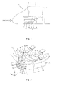
- Fig. 1 is a left side view showing a state where an obstacle deflector 10 according to the embodiment of the present invention is attached to a railcar 1.
- the obstacle deflector 10 configured to protect from an obstacle on a railway track a carbody 3 of a first car 2 of the railcar 1 that travels at high speed is attached to a lower front portion of an underframe 4 of the carbody 3.
- the obstacle deflector 10 includes an obstacle deflecting plate 11 configured to protect the carbody from the obstacle and a supporting device 12 configured to couple the obstacle deflecting plate 11 to the underframe 4.
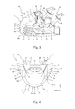
- Fig. 2 is a perspective view of the obstacle deflector 10 according to the embodiment of the present invention when viewed from a diagonally forward upper left side.
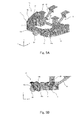
- Fig. 3 is a perspective view of the obstacle deflector 10 shown in Fig. 2 when viewed from a diagonally backward lower left side.
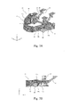
- Fig. 4 is a plan view of the obstacle deflector 10 shown in Fig. 2 .
- a railcar traveling direction front-rear direction
- Y railcar width direction
- Z a vertical direction
- the obstacle deflector 10 is made of a metal material, such as steel or aluminum alloy, to have a symmetrical shape.
- the obstacle deflecting plate 11 includes: a main plate portion 13 provided to receive the obstacle on a front side by its surface and having a circular-arc curved shape that is convex toward the front side in the traveling direction in plan view; an upper sub plate portion 14 projecting rearward from an upper end portion of the main plate portion 13; a lower sub plate portion 15 projecting rearward from a lower end portion of the main plate portion 13; and a plurality of (in the present embodiment, two) middle sub plate portions 16 and 17 projecting rearward from a vertically middle portion of the main plate portion 13 and provided to be spaced apart from each other in the vertical direction.
- the main plate portion 13 includes: a front end portion 13a curved in a convex shape; and a pair of side portions 13b continuously extending from the front end portion 13a rearward in the traveling direction at both left and right sides of the front end portion 13a.
- the main plate portion 13 is provided such that a normal direction thereof substantially corresponds to a horizontal direction.
- a portion corresponding to one third from the front end is the front end portion 13a, and a remaining portion corresponding to two third is the side portion 13b.
- a plurality of (in the present embodiment, four) plate-shaped anti-climbers 29 to 32 project forward from the front end portion 13a of the main plate portion 13 so as to be spaced apart from one another in an upper-lower direction.
- Each of the upper sub plate portion 14 and the lower sub plate portion 15 is provided to continuously extend from the front end portion 13a of the main plate portion 13 to rear ends of a pair of left and right side portions 13b.
- the upper sub plate portion 14 and the lower sub plate portion 15 are respectively fixed to an upper end edge and lower end edge of the main plate portion 13 by, for example, welding.
- a projecting amount of a portion that is a part of the upper sub plate portion 14 and projects from the front end portion 13a of the main plate portion 13 and a projecting amount of a portion that is a part of the lower sub plate portion 15 and projects from the front end portion 13a of the main plate portion 13 are respectively smaller than a projecting amount of a portion that is a part of the upper sub plate portion 14 and projects from the side portion 13b of the main plate portion 13 and a projecting amount of a portion that is a part of the lower sub plate portion 15 and projects from the side portion 13b of the main plate portion 13.
- the upper sub plate portion 14 includes a front constant region 14a, gradually increasing regions 14b, and rear constant regions 14c
- the lower sub plate portion 15 includes a front constant region 15a, gradually increasing regions 15b, and rear constant regions 15c.
- Each of the front constant regions 14a and 15a projects from the front end portion 13a of the main plate portion 13, and the projecting amount thereof is substantially constant.
- Each of the gradually increasing regions 14b and 15b projects from the side portion 13b of the main plate portion 13 so as to be smoothly continuous with the front constant region 14a or 15a, and the projecting amount thereof gradually increases as the gradually increasing region 14b or 15b extends rearward.
- Each of the rear constant regions 14c and 15c projects from the side portion 13b of the main plate portion 13 so as to be continuous with a rear side of the gradually increasing region 14b or 15b, and the projecting amount thereof is substantially constant.
- the lengths of the front constant regions 14a and 15a are respectively larger than the lengths of the gradually increasing regions 14b and 15b.
- Each of the projecting amounts of the front constant regions 14a and 15a is smaller than a vertical width of the main plate portion 13.
- Each of the projecting amounts of the rear constant regions 14c and 15c and the maximum projecting amounts of the gradually increasing regions 14b and 15b is twice or more as large as each of the projecting amounts of the front constant regions 14a and 15a.
- Each of the middle sub plate portions 16 and 17 is provided to continuously extend from the front end portion 13a of the main plate portion 13 to below-described box portions 18 and is fixed to a rear surface of the main plate portion 13 by, for example, welding.
- Each of the projecting amounts of the middle sub plate portions 16 and 17 is substantially the same as each of the projecting amounts of the front constant regions 14a and 15a of the upper sub plate portion 14 and the lower sub plate portion 15.
- Each of the sub plate portions 14 to 17 is provided such that a normal direction thereof substantially corresponds to the vertical direction.
- the sub plate portions 14 to 17 are provided at regular intervals in the upper-lower direction.
- the sub plate portions 14 to 17 and the anti-climbers 29 to 32 are provided to sandwich the main plate portion 13.
- the sub plate portions 14 to 17 are located at substantially the same heights as the anti-climbers 29 to 32, respectively.
- the box portions 18 that are hollow hexahedrons are respectively provided at back surface sides (inner surface sides) of rear portions of the side portions 13b of the main plate portion 13.
- An upper surface and lower surface of each of the box portions 18 are respectively formed by the rear constant regions 14c and 15c of the upper sub plate portion 14 and the lower sub plate portion 15.
- An outer side surface of the box portion 18 is formed by the rear portion of the side portion 13b of the main plate portion 13.
- An inner side surface of the box portion 18 is formed by an inner plate member 19 joined by, for example, welding to projecting ends of the rear constant regions 14c and 15c of the upper sub plate portion 14 and the lower sub plate portion 15.
- a front surface and rear surface of the box portion 18 are respectively formed by a front plate member 20 and a rear plate member 21 that are joined by, for example, welding to a lower surface of the upper sub plate portion 14, an upper surface of the lower sub plate portion 15, and a back surface of the main plate portion 13.
- left and right end portions of each of the middle sub plate portions 16 and 17 respectively contact the front plate members 20 of the box portions 18.
- an intersection point A of the front surface of the box portion 18 and the main plate portion 13, that is, the intersection point A of the front plate member 20 of the box portion 18 and the main plate portion 13 is located outside a railway track R in the railcar width direction.
- the supporting device 12 is coupled to the main plate portion 13 via the box portions 18.
- the supporting device 12 is formed by a rigid body made of a metal, such as steel.
- the supporting device 12 is configured to couple the obstacle deflecting plate 11 to the underframe 4 (see Fig. 1 ).
- the supporting device 12 includes: first supporting members 25 configured to prevent the displacement of the obstacle deflecting plate 11 in the upper-lower direction; second supporting members 26 configured to prevent the displacement of the obstacle deflecting plate 11 in the front-rear direction; a third supporting member 27 configured to prevent the displacement of the obstacle deflecting plate 11 in the railcar width direction; and attaching members 23 used to attach the supporting members 25 to 27 to the box portions 18 of the obstacle deflecting plate 11.
- Attaching plates 24 are respectively fixed to sides of the attaching member 23 by, for example, welding, the sides being respectively opposed to the box portions 18.
- the attaching plates 24 are respectively fixed to the inner plate members 19 of the box portions 18 by bolts.
- coupling surfaces where the obstacle deflecting plate 11 and the supporting device 12 are coupled to each other that is, coupling surfaces at each of which the attaching plate 24 and the inner plate member 19 are coupled to each other are inclined so as to widen outward in the railcar width direction as they extend rearward.
- each of the attaching members 23 includes: an upper surface 23a that is a horizontal surface; a back surface 23b that is a vertical surface whose normal direction extends rearward in the traveling direction; and an inner surface 23c that is a vertical surface formed at right angle to the back surface 23b.
- Each of the first supporting members 25 extends upward in a state where a lower end thereof is fixed to the upper surface 23a of the attaching member 23. The other end of the first supporting member 25 is attached to a lower portion of the underframe 4 (see Fig. 1 ).
- Each of the second supporting members 26 extends to a diagonally backward upper side in a state where a front end thereof is fixed to the back surface 23b of the attaching member 23.
- the other end of the second supporting member 26 is attached to the lower portion of the underframe 4 (see Fig. 1 ).
- the third supporting member 27 is horizontally attached so as to couple the opposing inner surfaces 23c of the left and right attaching members 23. The displacement of the obstacle deflecting plate 11 in respective directions can be prevented by the supporting device 12 configured as above.
- the sub plate portions 14 to 17 suppress the deformation of the main plate portion 13. Therefore, the stiffness of the obstacle deflecting plate 11 can be increased without increasing the weight of the obstacle deflector 10.
- the main plate portion 13, the upper sub plate portion 14, and the lower sub plate portion 15 form a vertical cross-sectional shape that is convex toward the front side, the stiffness of the obstacle deflecting plate 11 can be effectively increased.
- the middle sub plate portions 16 and 17 also suppress the deformation of the main plate portion 13, the stiffness of the obstacle deflecting plate 11 when the obstacle crashes with the vertically middle portion of the main plate portion 13 can be more effectively increased. Therefore, the absorption energy per unit weight at the time of the crash increases, and the efficient energy absorption can be realized while realizing the light weight.
- the upper sub plate portion 14 and the lower sub plate portion 15 are respectively provided with the gradually increasing regions 14b and 15b, the strengths of portions, close to the supporting device 12, of the upper sub plate portion 14 and the lower sub plate portion 15 increase. Therefore, the stiffness of the obstacle deflecting plate 11 can be further increased. Since the strengths of the portions, close to the supporting device 12, of the upper sub plate portion 14 and the lower sub plate portion 15 increase, the main plate portion 13 can be prevented from deforming intensively at a portion close to the supporting device 12, and a crash energy absorption performance by the front end portion 13a of the main plate portion 13 can be improved.
- the constant regions 14a and 15a are respectively longer than the gradually increasing regions 14b and 15b. Therefore, an initial load when the obstacle crashes with the front end portion 13a of the main plate portion 13 is prevented from becoming excessive, and the impact transmitted to the carbody 3 can be reduced. Therefore, both the crash energy absorption performance and an impact reducing performance can be suitably realized.
- each of the box portions 18 is formed by utilizing a part of the main plate portion 13, a part of the upper sub plate portion 14, and a part of the lower sub plate portion 15, the number of parts and the device weight can be reduced.
- each of the middle sub plate portions 16 and 17 are restricted by the front plate members 20 of the box portions 18. Therefore, when the obstacle crashes with the main plate portion 13, the middle sub plate portions 16 and 17 deform. With this, the crash energy can be absorbed more effectively. Further, in the obstacle deflecting plate 11, since the portion of the intersection point A having high strength is located outside the railway track R in the railcar width direction, the portion of the intersection point A is located at an adequately rear side of the obstacle deflecting plate 11, so that the impact on the carbody can be adequately absorbed by the portion located at a front side of the intersection point A. Moreover, a plurality of anti-climbers 29 to 32 are provided on a front surface of the front end portion 13a of the main plate portion 13. Therefore, when the obstacle crashes with the obstacle deflecting plate 11 from the front, the obstacle can be prevented from getting on the obstacle deflecting plate 11.
- a portion extending from the front end to the portion (box portion 18) coupled to the supporting device 12 is not supported by the carbody, and the front-rear-direction size of the portion that deforms at the time of the crash is set to an adequate size. Therefore, an adequate deformation stroke can be obtained even in a case where the railcars crash with each other.
- the obstacle deflector 10 can be easily attached to the carbody.
- the box portions 18 are the hollow hexahedrons. However, an absorber may be accommodated in each box portion 18.
- the left and right end portions of each of the middle sub plate portions 16 and 17 respectively contact the front plate members 20 of the box portions 18.
- the left and right end portions of each of the middle sub plate portions 16 and 17 may be respectively fixed to the front plate members 20 of the box portions 18 by, for example, welding.
- the present invention is not limited to the above-described embodiment. Modifications, additions, and eliminations may be made within the spirit of the present invention.
- Table 1 shows the material physical property values used in the analysis, and Table 2 shows allowable stresses (MPa).
- SS400 was used for the obstacle deflecting plate 11
- A5083-O was used for the attaching member 23 and the first supporting member 25
- A6N01-T5 was used for the second supporting member 26 and the third supporting member 27.
- Fig. 5A is a perspective view showing a state where in Finite Element Analysis, a hard sphere B1 of 100 kg crashes with a center of the obstacle deflector 10 from the front at 350 km/h
- Fig. 5B is a side view showing the state.
- Fig. 6 is a graph showing temporal changes of loads acting on the carbody in the case of Figs. 5A and 5B .
- the initial load in the direction X was high to some extent.
- the upper sub plate portion 14 and the lower sub plate portion 15 were respectively provided with the gradually increasing regions 14b and 15b.
- the main plate portion 13 was prevented from deforming intensively at the portion close to the supporting device 12. Therefore, it was confirmed that the load transmitted to the carbody was successfully prevented from greatly varying with time.
- the strengths of the portions, close to the supporting device 12, of the obstacle deflecting plate 11 were increased by the box portion 18. Therefore, even when the hard sphere B1 crashed with the main plate portion 13, and the front end portion 13a greatly deformed, the front end portion of the obstacle deflecting plate 11 was prevented from twisting so as to bend downward. On this account, it was confirmed that the deformed front end portion of the obstacle deflecting plate 11 was successfully prevented from interfering with the ground.
- Fig. 7A is a perspective view showing a state where in Finite Element Analysis, the hard sphere of 100 kg crashes with the side surface of the obstacle deflector from the front at 350 km/h
- Fig. 7B is a side view showing the state
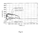
- Fig. 8 is a graph showing temporal changes of the loads acting on the carbody in the case of Fig. 7A .
- Figs. 7A, 7B , and 8 in a case where the hard sphere B1 crashed with the side portion 13b of the main plate portion 13 of the obstacle deflecting plate 11, both the initial load in the direction X and the initial load in the direction Y were high.
- each of the peak value of the initial load in the direction X and the peak value of the initial load in the direction Y shown in Fig. 8 was smaller than the peak value of the initial load in the direction X shown in Fig. 6 , but those loads acted for a long period of time, and the crash energy was adequately absorbed.
- the main plate portion 13 was prevented from deforming intensively at the portion close to the supporting device 12; the load transmitted to the carbody was successfully prevented from greatly varying with time; and the deformed front end portion of the obstacle deflecting plate 11 was successfully prevented from interfering with the ground.
- Fig. 9A is a perspective view showing a state where in Finite Element Analysis, a hard wall B2 is pushed into the obstacle deflecting plate 11 of the obstacle deflector 10 at 36 km/h, and a pushed amount is 500 mm
- Fig. 9B is a side view showing the state
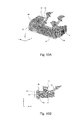
- Fig. 10A is a perspective view showing a state where the obstacle deflecting plate 11 is further pushed from the state shown in Fig. 9 , and the pushed amount is 700 mm
- Fig. 10B is a side view showing the state.
- Fig. 11 is a graph showing a relation between the load acting on the carbody and the pushed amount in Figs. 9A, 9B , 10A, and 10B . As shown in Figs.
Landscapes
- Engineering & Computer Science (AREA)
- Mechanical Engineering (AREA)
- Life Sciences & Earth Sciences (AREA)
- Wood Science & Technology (AREA)
- Transportation (AREA)
- Vibration Dampers (AREA)
- Train Traffic Observation, Control, And Security (AREA)
Abstract
The present invention provides an obstacle deflector provided at a front portion of an underframe of a carbody of a railcar, and the obstacle deflector includes an obstacle deflecting plate configured to protect the carbody from an obstacle on a railway track when the railcar is traveling. The obstacle deflecting plate includes a main plate portion provided to receive the obstacle by a surface thereof and having a curved shape that is convex toward a front side in a traveling direction in plan view and a sub plate portion projecting toward a rear side from the main plate portion, and the sub plate portion is continuously provided along the main plate portion so as to extend from a convex, curved front end portion of the main plate portion toward a pair of left and right side portions of the main plate portion, the left and right side portions being located at the rear side in the traveling direction.
Description
- The present invention relates to an obstacle deflector provided at a front portion of an underframe of a carbody of a railcar.
- Conventionally, to protect a carbody of a railcar from an obstacle on a railway track while the railcar is traveling at high speed, an obstacle deflector is being attached to a front portion of an underframe of a carbody of a first car of the railcar. A typical obstacle deflector includes an obstacle deflecting plate having a curved shape that is convex toward a front side in a traveling direction in plan view, and the obstacle deflecting plate is configured to receive the obstacle (see Japanese Laid-Open Patent Application Publication No.
2005-53346 - Since the railcars are increasing in speed in recent years, the crash energy generated when the obstacle crashes with the railcar tends to increase. Therefore, when designing an obstacle deflector, the crashworthiness of the obstacle deflector needs to be improved for the purpose of absorbing a large amount of crash energy.
- A railcar described in Japanese Laid-Open Patent Application Publication No.
2006-168709 - Here, an object of the present invention is to provide an obstacle deflector of a railcar, which is improved in an absorption energy per unit weight at the time of crash, is light in weight, and realizes efficient energy absorption.
- An obstacle deflector of a railcar according to the present invention is an obstacle deflector provided at a front portion of an underframe of a carbody of a railcar, the obstacle deflector including an obstacle deflecting plate configured to protect the carbody from an obstacle on a railway track when the railcar is traveling, wherein: the obstacle deflecting plate includes a main plate portion provided to receive the obstacle by a surface thereof and having a curved shape that is convex toward a front side in a traveling direction in plan view and a sub plate portion projecting toward a rear side from the main plate portion; and the sub plate portion is continuously provided along the main plate portion so as to extend from a convex, curved front end portion of the main plate portion toward a pair of left and right side portions of the main plate portion, the left and right side portions being located at the rear side in the traveling direction.
- According to the above configuration, in a case where the obstacle on the railway track crashes with the surface of the main plate portion of the obstacle deflecting plate, the sub plate portion suppresses the deformation of the main plate portion. Therefore, the stiffness of the obstacle deflecting plate can be increased without increasing the weight of the obstacle deflector. On this account, the absorption energy per unit weight at the time of the crash increases, and the efficient energy absorption can be realized while realizing the light weight.
-
- [
Fig. 1] Fig. 1 is a left side view showing a state where an obstacle deflector according to an embodiment of the present invention is attached to a railcar. - [
Fig. 2] Fig. 2 is a perspective view of the obstacle deflector according to the embodiment of the present invention when viewed from a diagonally forward upper left side. - [
Fig. 3] Fig. 3 is a perspective view of the obstacle deflector shown inFig. 2 when viewed from a diagonally backward lower left side. - [
Fig. 4] Fig. 4 is a plan view of the obstacle deflector shown inFig. 2 . - [
Figs. 5A and 5B] Fig. 5A is a perspective view showing a state where in Finite Element Analysis, a hard sphere of 100 kg crashes with a center of the obstacle deflector from a front side at 350 km/h.Fig. 5B is a side view showing the state. - [
Fig. 6] Fig. 6 is a graph showing temporal changes of loads acting on a carbody in the case ofFig. 5 . - [
Figs. 7A and 7B] Fig. 7A is a perspective view showing a state where in Finite Element Analysis, the hard sphere of 100 kg crashes with a side surface of the obstacle deflector from the front side at 350 km/h.Fig. 7B is a side view showing the state. - [
Fig. 8] Fig. 8 is a graph showing temporal changes of loads acting on the carbody in the case ofFig. 7 . - [
Figs. 9A and 9B] Fig. 9A is a perspective view showing a state where in Finite Element Analysis, a hard wall is pushed into an obstacle deflecting plate of the obstacle deflector at 36 km/h, and a pushed amount is 500 mm.Fig. 9B is a side view showing the state. - [
Figs. 10A and 10B] Fig. 10A is a perspective view showing a state where the obstacle deflecting plate is further pushed from the state shown inFig. 9A , and the pushed amount is 700 mm.Fig. 10B is a side view showing the state. - [
Fig. 11] Fig. 11 is a graph showing a relation between the load acting on the carbody and the pushed amount inFigs 9A, 9B ,10A, and 10B . - Hereinafter, an embodiment of the present invention will be explained in reference to the drawings.
-
Fig. 1 is a left side view showing a state where anobstacle deflector 10 according to the embodiment of the present invention is attached to arailcar 1. As shown inFig. 1 , theobstacle deflector 10 configured to protect from an obstacle on a railway track a carbody 3 of afirst car 2 of therailcar 1 that travels at high speed is attached to a lower front portion of an underframe 4 of the carbody 3. Theobstacle deflector 10 includes anobstacle deflecting plate 11 configured to protect the carbody from the obstacle and a supportingdevice 12 configured to couple theobstacle deflecting plate 11 to the underframe 4. -
Fig. 2 is a perspective view of theobstacle deflector 10 according to the embodiment of the present invention when viewed from a diagonally forward upper left side.Fig. 3 is a perspective view of theobstacle deflector 10 shown inFig. 2 when viewed from a diagonally backward lower left side.Fig. 4 is a plan view of theobstacle deflector 10 shown inFig. 2 . In the following explanation, a railcar traveling direction (front-rear direction) is denoted by X, a railcar width direction is denoted by Y, and a vertical direction is denoted by Z. As shown inFigs. 2 to 4 , theobstacle deflector 10 is made of a metal material, such as steel or aluminum alloy, to have a symmetrical shape. Theobstacle deflecting plate 11 includes: amain plate portion 13 provided to receive the obstacle on a front side by its surface and having a circular-arc curved shape that is convex toward the front side in the traveling direction in plan view; an uppersub plate portion 14 projecting rearward from an upper end portion of themain plate portion 13; a lowersub plate portion 15 projecting rearward from a lower end portion of themain plate portion 13; and a plurality of (in the present embodiment, two) middlesub plate portions main plate portion 13 and provided to be spaced apart from each other in the vertical direction. - The
main plate portion 13 includes: afront end portion 13a curved in a convex shape; and a pair ofside portions 13b continuously extending from thefront end portion 13a rearward in the traveling direction at both left and right sides of thefront end portion 13a. Themain plate portion 13 is provided such that a normal direction thereof substantially corresponds to a horizontal direction. In the present embodiment, in the entire length of themain plate portion 13 in the front-rear direction X, a portion corresponding to one third from the front end is thefront end portion 13a, and a remaining portion corresponding to two third is theside portion 13b. A plurality of (in the present embodiment, four) plate-shaped anti-climbers 29 to 32 project forward from thefront end portion 13a of themain plate portion 13 so as to be spaced apart from one another in an upper-lower direction. - Each of the upper
sub plate portion 14 and the lowersub plate portion 15 is provided to continuously extend from thefront end portion 13a of themain plate portion 13 to rear ends of a pair of left andright side portions 13b. The uppersub plate portion 14 and the lowersub plate portion 15 are respectively fixed to an upper end edge and lower end edge of themain plate portion 13 by, for example, welding. A projecting amount of a portion that is a part of the uppersub plate portion 14 and projects from thefront end portion 13a of themain plate portion 13 and a projecting amount of a portion that is a part of the lowersub plate portion 15 and projects from thefront end portion 13a of themain plate portion 13 are respectively smaller than a projecting amount of a portion that is a part of the uppersub plate portion 14 and projects from theside portion 13b of themain plate portion 13 and a projecting amount of a portion that is a part of the lowersub plate portion 15 and projects from theside portion 13b of themain plate portion 13. Specifically, the uppersub plate portion 14 includes a frontconstant region 14a, gradually increasingregions 14b, and rearconstant regions 14c, and the lowersub plate portion 15 includes a frontconstant region 15a, gradually increasingregions 15b, and rearconstant regions 15c. Each of the frontconstant regions front end portion 13a of themain plate portion 13, and the projecting amount thereof is substantially constant. Each of the gradually increasingregions side portion 13b of themain plate portion 13 so as to be smoothly continuous with the frontconstant region region constant regions side portion 13b of themain plate portion 13 so as to be continuous with a rear side of the gradually increasingregion - In a direction along the
main plate portion 13, the lengths of the frontconstant regions regions constant regions main plate portion 13. Each of the projecting amounts of the rearconstant regions regions constant regions - Each of the middle
sub plate portions front end portion 13a of themain plate portion 13 to below-describedbox portions 18 and is fixed to a rear surface of themain plate portion 13 by, for example, welding. Each of the projecting amounts of the middlesub plate portions constant regions sub plate portion 14 and the lowersub plate portion 15. Each of thesub plate portions 14 to 17 is provided such that a normal direction thereof substantially corresponds to the vertical direction. Thesub plate portions 14 to 17 are provided at regular intervals in the upper-lower direction. Thesub plate portions 14 to 17 and the anti-climbers 29 to 32 are provided to sandwich themain plate portion 13. In addition, thesub plate portions 14 to 17 are located at substantially the same heights as the anti-climbers 29 to 32, respectively. - The
box portions 18 that are hollow hexahedrons are respectively provided at back surface sides (inner surface sides) of rear portions of theside portions 13b of themain plate portion 13. An upper surface and lower surface of each of thebox portions 18 are respectively formed by the rearconstant regions sub plate portion 14 and the lowersub plate portion 15. An outer side surface of thebox portion 18 is formed by the rear portion of theside portion 13b of themain plate portion 13. An inner side surface of thebox portion 18 is formed by aninner plate member 19 joined by, for example, welding to projecting ends of the rearconstant regions sub plate portion 14 and the lowersub plate portion 15. A front surface and rear surface of thebox portion 18 are respectively formed by afront plate member 20 and arear plate member 21 that are joined by, for example, welding to a lower surface of the uppersub plate portion 14, an upper surface of the lowersub plate portion 15, and a back surface of themain plate portion 13. In the direction along themain plate portion 13, left and right end portions of each of the middlesub plate portions front plate members 20 of thebox portions 18. In plan view, an intersection point A of the front surface of thebox portion 18 and themain plate portion 13, that is, the intersection point A of thefront plate member 20 of thebox portion 18 and themain plate portion 13 is located outside a railway track R in the railcar width direction. - The supporting
device 12 is coupled to themain plate portion 13 via thebox portions 18. The supportingdevice 12 is formed by a rigid body made of a metal, such as steel. The supportingdevice 12 is configured to couple theobstacle deflecting plate 11 to the underframe 4 (seeFig. 1 ). The supportingdevice 12 includes: first supportingmembers 25 configured to prevent the displacement of theobstacle deflecting plate 11 in the upper-lower direction; second supportingmembers 26 configured to prevent the displacement of theobstacle deflecting plate 11 in the front-rear direction; a third supportingmember 27 configured to prevent the displacement of theobstacle deflecting plate 11 in the railcar width direction; and attachingmembers 23 used to attach the supportingmembers 25 to 27 to thebox portions 18 of theobstacle deflecting plate 11. Attachingplates 24 are respectively fixed to sides of the attachingmember 23 by, for example, welding, the sides being respectively opposed to thebox portions 18. The attachingplates 24 are respectively fixed to theinner plate members 19 of thebox portions 18 by bolts. In plan view, coupling surfaces where theobstacle deflecting plate 11 and the supportingdevice 12 are coupled to each other, that is, coupling surfaces at each of which the attachingplate 24 and theinner plate member 19 are coupled to each other are inclined so as to widen outward in the railcar width direction as they extend rearward. - Specifically, each of the attaching
members 23 includes: anupper surface 23a that is a horizontal surface; aback surface 23b that is a vertical surface whose normal direction extends rearward in the traveling direction; and aninner surface 23c that is a vertical surface formed at right angle to theback surface 23b. Each of the first supportingmembers 25 extends upward in a state where a lower end thereof is fixed to theupper surface 23a of the attachingmember 23. The other end of the first supportingmember 25 is attached to a lower portion of the underframe 4 (seeFig. 1 ). Each of the second supportingmembers 26 extends to a diagonally backward upper side in a state where a front end thereof is fixed to theback surface 23b of the attachingmember 23. The other end of the second supportingmember 26 is attached to the lower portion of the underframe 4 (seeFig. 1 ). The third supportingmember 27 is horizontally attached so as to couple the opposinginner surfaces 23c of the left and right attachingmembers 23. The displacement of theobstacle deflecting plate 11 in respective directions can be prevented by the supportingdevice 12 configured as above. - According to the configuration explained as above, in a case where the obstacle on the railway track crashes with a front surface of the
main plate portion 13 of theobstacle deflecting plate 11, thesub plate portions 14 to 17 suppress the deformation of themain plate portion 13. Therefore, the stiffness of theobstacle deflecting plate 11 can be increased without increasing the weight of theobstacle deflector 10. In addition, since themain plate portion 13, the uppersub plate portion 14, and the lowersub plate portion 15 form a vertical cross-sectional shape that is convex toward the front side, the stiffness of theobstacle deflecting plate 11 can be effectively increased. Further, since the middlesub plate portions main plate portion 13, the stiffness of theobstacle deflecting plate 11 when the obstacle crashes with the vertically middle portion of themain plate portion 13 can be more effectively increased. Therefore, the absorption energy per unit weight at the time of the crash increases, and the efficient energy absorption can be realized while realizing the light weight. - Since the upper
sub plate portion 14 and the lowersub plate portion 15 are respectively provided with the gradually increasingregions device 12, of the uppersub plate portion 14 and the lowersub plate portion 15 increase. Therefore, the stiffness of theobstacle deflecting plate 11 can be further increased. Since the strengths of the portions, close to the supportingdevice 12, of the uppersub plate portion 14 and the lowersub plate portion 15 increase, themain plate portion 13 can be prevented from deforming intensively at a portion close to the supportingdevice 12, and a crash energy absorption performance by thefront end portion 13a of themain plate portion 13 can be improved. - In addition, in the upper
sub plate portion 14 and the lowersub plate portion 15, in the direction along themain plate portion 13 in plan view, theconstant regions regions front end portion 13a of themain plate portion 13 is prevented from becoming excessive, and the impact transmitted to the carbody 3 can be reduced. Therefore, both the crash energy absorption performance and an impact reducing performance can be suitably realized. - The strengths of portions, close to the supporting
device 12, of theobstacle deflecting plate 11 are increased by thebox portions 18. Therefore, even when the obstacle crashes with themain plate portion 13, and thefront end portion 13a greatly deforms, the front end portion of theobstacle deflecting plate 11 can be prevented from twisting so as to bend downward, and the deformed front end portion of theobstacle deflecting plate 11 can be prevented from interfering with ground. Further, since each of thebox portions 18 is formed by utilizing a part of themain plate portion 13, a part of the uppersub plate portion 14, and a part of the lowersub plate portion 15, the number of parts and the device weight can be reduced. - Left and right end portions of each of the middle
sub plate portions front plate members 20 of thebox portions 18. Therefore, when the obstacle crashes with themain plate portion 13, the middlesub plate portions obstacle deflecting plate 11, since the portion of the intersection point A having high strength is located outside the railway track R in the railcar width direction, the portion of the intersection point A is located at an adequately rear side of theobstacle deflecting plate 11, so that the impact on the carbody can be adequately absorbed by the portion located at a front side of the intersection point A. Moreover, a plurality ofanti-climbers 29 to 32 are provided on a front surface of thefront end portion 13a of themain plate portion 13. Therefore, when the obstacle crashes with theobstacle deflecting plate 11 from the front, the obstacle can be prevented from getting on theobstacle deflecting plate 11. - In the
main plate portion 13, a portion extending from the front end to the portion (box portion 18) coupled to the supportingdevice 12 is not supported by the carbody, and the front-rear-direction size of the portion that deforms at the time of the crash is set to an adequate size. Therefore, an adequate deformation stroke can be obtained even in a case where the railcars crash with each other. In addition, theobstacle deflector 10 can be easily attached to the carbody. - In the above embodiment, the
box portions 18 are the hollow hexahedrons. However, an absorber may be accommodated in eachbox portion 18. In addition, in the above embodiment, in the direction along themain plate portion 13, the left and right end portions of each of the middlesub plate portions front plate members 20 of thebox portions 18. However, the left and right end portions of each of the middlesub plate portions front plate members 20 of thebox portions 18 by, for example, welding. The present invention is not limited to the above-described embodiment. Modifications, additions, and eliminations may be made within the spirit of the present invention. - Next, an analytical result in a case where the obstacle is caused to crash with the
obstacle deflector 10 by computer simulation using Finite Element Analysis will be explained in reference toFigs. 5A to 11 . Analysis conditions (1) to (4) are as follows. - Mesh finite element model of the
obstacle deflector 10 having the shape shown inFig. 2 (seeFigs. 5A and 5B ) - Table 1 shows the material physical property values used in the analysis, and Table 2 shows allowable stresses (MPa). SS400 was used for the
obstacle deflecting plate 11, A5083-O was used for the attachingmember 23 and the first supportingmember 25, and A6N01-T5 was used for the second supportingmember 26 and the third supportingmember 27. -
Table 1 Quality of material Young's modulus (MPa) Poisson's ratio Mass density (ton/mm3) SS400 205800. 0.30 7.85*10-9 A6N01-T5 70000. 0.33 2.70*10-9 A5083-O 70000 0.33 2.70*10-9 -
Table 2 Quality of material Proof stress Tensile strength SS400 245 400 A6N01-T5 (t<6) 205 245 ↑ (6<t<12) 175 225 A5083-O 125 275 - Analysis code: LS-DYNA Ver.971 (Livermore Software Technology Corporation)
Single Precision Version, Explicit Method (Crash Analysis)
(4) Analysis conditions
Table 3 shows analysis cases. -
Table 3 Analysis details Load position Case 1 ( Figs. 5A, 5B , and6 )Hard sphere of 100 kg crashes with obstacle deflecting plate at 350 km/h. Center Case 2 ( Figs. 7A, 7B , and8 )Hard sphere of 100 kg crashes with obstacle deflecting plate at 350 km/h. Side surface Case 3 ( Figs. 9A to 11 )Hard wall is pushed into obstacle deflecting plate at 36 km/h. Center -
Fig. 5A is a perspective view showing a state where in Finite Element Analysis, a hard sphere B1 of 100 kg crashes with a center of theobstacle deflector 10 from the front at 350 km/h, andFig. 5B is a side view showing the state.Fig. 6 is a graph showing temporal changes of loads acting on the carbody in the case ofFigs. 5A and 5B . As shown inFigs. 5A, 5B , and6 , in a case where the hard sphere B1 crashed with thefront end portion 13a of themain plate portion 13 of theobstacle deflecting plate 11, the deformation of themain plate portion 13 was suppressed by thesub plate portions 14 to 17. Therefore, the initial load in the direction X was high to some extent. Since the projecting amounts of theconstant regions sub plate portion 14 and the lowersub plate portion 15 were small, the initial load when the hard sphere B1 crashed with thefront end portion 13a of themain plate portion 13 was prevented from becoming too high. Therefore, it was confirmed that the crash energy was successfully absorbed while preventing the impact transmitted to the carbody 3 from becoming excessive. - The upper
sub plate portion 14 and the lowersub plate portion 15 were respectively provided with the gradually increasingregions regions main plate portion 13 was prevented from deforming intensively at the portion close to the supportingdevice 12. Therefore, it was confirmed that the load transmitted to the carbody was successfully prevented from greatly varying with time. In addition, the strengths of the portions, close to the supportingdevice 12, of theobstacle deflecting plate 11 were increased by thebox portion 18. Therefore, even when the hard sphere B1 crashed with themain plate portion 13, and thefront end portion 13a greatly deformed, the front end portion of theobstacle deflecting plate 11 was prevented from twisting so as to bend downward. On this account, it was confirmed that the deformed front end portion of theobstacle deflecting plate 11 was successfully prevented from interfering with the ground. -
Fig. 7A is a perspective view showing a state where in Finite Element Analysis, the hard sphere of 100 kg crashes with the side surface of the obstacle deflector from the front at 350 km/h, andFig. 7B is a side view showing the state.Fig. 8 is a graph showing temporal changes of the loads acting on the carbody in the case ofFig. 7A . As shown inFigs. 7A, 7B , and8 , in a case where the hard sphere B1 crashed with theside portion 13b of themain plate portion 13 of theobstacle deflecting plate 11, both the initial load in the direction X and the initial load in the direction Y were high. It was confirmed that each of the peak value of the initial load in the direction X and the peak value of the initial load in the direction Y shown inFig. 8 was smaller than the peak value of the initial load in the direction X shown inFig. 6 , but those loads acted for a long period of time, and the crash energy was adequately absorbed. In addition, as withFig. 6 , it was confirmed that: themain plate portion 13 was prevented from deforming intensively at the portion close to the supportingdevice 12; the load transmitted to the carbody was successfully prevented from greatly varying with time; and the deformed front end portion of theobstacle deflecting plate 11 was successfully prevented from interfering with the ground. -
Fig. 9A is a perspective view showing a state where in Finite Element Analysis, a hard wall B2 is pushed into theobstacle deflecting plate 11 of theobstacle deflector 10 at 36 km/h, and a pushed amount is 500 mm, andFig. 9B is a side view showing the state.Fig. 10A is a perspective view showing a state where theobstacle deflecting plate 11 is further pushed from the state shown inFig. 9 , and the pushed amount is 700 mm, andFig. 10B is a side view showing the state.Fig. 11 is a graph showing a relation between the load acting on the carbody and the pushed amount inFigs. 9A, 9B ,10A, and 10B . As shown inFigs. 9A to 11 , it was confirmed that in a case where the hard wall B2 whose length in the railcar width direction was substantially the same as that of theobstacle deflecting plate 11 was pushed into themain plate portion 13, the initial load in the direction X became high, and after that, while the pushed amount was increasing, the load acted, and the crash energy was absorbed. Then, when the pushed amount exceeded 500 mm, the gradually increasingregions sub plate portion 14 and the lowersub plate portion 15 greatly buckled so as to become wavy, and this again increased the load. With this, it was confirmed that the crash energy was successfully absorbed not only at an initial stage of the crash but also at a later stage of the crash.
Claims (10)
- An obstacle deflector provided at a front portion of an underframe of a carbody of a railcar,
the obstacle deflector comprising
an obstacle deflecting plate configured to protect the carbody from an obstacle on a railway track when the railcar is traveling, wherein:the obstacle deflecting plate includes a main plate portion provided to receive the obstacle by a surface thereof and having a curved shape that is convex toward a front side in a traveling direction in plan view and a sub plate portion projecting toward a rear side from the main plate portion; andthe sub plate portion is continuously provided along the main plate portion so as to extend from a convex, curved front end portion of the main plate portion toward a pair of left and right side portions of the main plate portion, the left and right side portions being located at the rear side in the traveling direction. - The obstacle deflector according to claim 1, comprising
a supporting device configured to couple the side portions of the obstacle deflecting plate to the underframe, wherein
the sub plate portion includes gradually increasing regions at portions projecting from the side portions, and projecting amounts of the gradually increasing regions gradually increase as the gradually increasing regions extend from the front end portion side to the supporting device side. - The obstacle deflector according to claim 2, wherein:the sub plate portion includes a constant region including a portion projecting from the front end portion, smoothly continuous with the gradually increasing regions, and having a substantially constant projecting amount; andin a direction along the main plate portion in plan view, the constant region is larger in length than each of the gradually increasing regions.
- The obstacle deflector according to claim 1, wherein
the sub plate portion includes an upper sub plate portion projecting toward the rear side from an upper end portion of the main plate portion and a lower sub plate portion projecting toward the rear side from a lower end portion of the main plate portion. - The obstacle deflector according to claim 1, wherein
the sub plate portion includes a middle sub plate portion projecting toward the rear side from a vertically middle portion of the main plate portion. - The obstacle deflector according to claim 1, comprising
a supporting device configured to couple the side portions of the obstacle deflecting plate to the underframe, wherein
the main plate portion and the supporting device are coupled to each other via box portions. - The obstacle deflector according to claim 6, wherein:the sub plate portion includes an upper sub plate portion projecting toward the rear side from an upper end portion of the main plate portion and a lower sub plate portion projecting toward the rear side from a lower end portion of the main plate portion;an upper surface and lower surface of each of the box portions are respectively formed by a part of the upper sub plate portion and a part of the lower sub plate portion;an outer side surface of each of the box portions is formed by a part of the main plate portion;an inner side surface of each of the box portions is formed by an inner plate member joined to a projecting end of the upper sub plate portion and a projecting end of the lower sub plate portion; anda front surface and rear surface of each of the box portions are respectively formed by a front plate member and a rear plate member, each of whose end edges are joined to a lower surface of the upper sub plate portion, an upper surface of the lower sub plate portion, and a back surface of the main plate portion.
- The obstacle deflector according to claim 6, wherein
in plan view, an intersection point of the main plate portion and each of front surfaces of the box portions is located outside a railway track in a left-right direction. - The obstacle deflector according to claim 6, wherein:the sub plate portion includes a middle sub plate portion projecting to the rear side from a vertically middle portion of the main plate portion; andin a direction along the main plate portion, left and right end portions of the middle sub plate portion respectively contact the box portions.
- The obstacle deflector according to claim 1, comprising a plate-shaped anti-climber projecting toward the front side from the main plate portion.
Applications Claiming Priority (2)
| Application Number | Priority Date | Filing Date | Title |
|---|---|---|---|
| JP2010258535A JP5584597B2 (en) | 2010-11-19 | 2010-11-19 | Railroad vehicle drainage device |
| PCT/JP2011/005675 WO2012066719A1 (en) | 2010-11-19 | 2011-10-11 | Obstacle removal device for railway rolling stock |
Publications (2)
| Publication Number | Publication Date |
|---|---|
| EP2641807A1 true EP2641807A1 (en) | 2013-09-25 |
| EP2641807A4 EP2641807A4 (en) | 2017-06-07 |
Family
ID=46083672
Family Applications (1)
| Application Number | Title | Priority Date | Filing Date |
|---|---|---|---|
| EP11841025.7A Withdrawn EP2641807A4 (en) | 2010-11-19 | 2011-10-11 | Obstacle removal device for railway rolling stock |
Country Status (5)
| Country | Link |
|---|---|
| US (1) | US9027485B2 (en) |
| EP (1) | EP2641807A4 (en) |
| JP (1) | JP5584597B2 (en) |
| CN (1) | CN103180194B (en) |
| WO (1) | WO2012066719A1 (en) |
Cited By (2)
| Publication number | Priority date | Publication date | Assignee | Title |
|---|---|---|---|---|
| WO2017097593A1 (en) * | 2015-12-10 | 2017-06-15 | Siemens Ag Österreich | Chassis for a rail vehicle |
| GB2577528A (en) * | 2018-09-27 | 2020-04-01 | Hitachi Ltd | Railway vehicle |
Families Citing this family (15)
| Publication number | Priority date | Publication date | Assignee | Title |
|---|---|---|---|---|
| KR20130109139A (en) * | 2010-09-20 | 2013-10-07 | 봄바디어 트랜스포테이션 게엠베하 | Lightweight compound cab structure for a rail vehicle |
| CA2857935C (en) * | 2011-12-02 | 2016-01-26 | Nippon Sharyo, Ltd. | Rolling stock |
| JP5758044B2 (en) * | 2012-02-21 | 2015-08-05 | 日本車輌製造株式会社 | Railway vehicle |
| WO2015092832A1 (en) * | 2013-12-18 | 2015-06-25 | 川崎重工業株式会社 | Collision energy absorption device for railway vehicle |
| CN104527704B (en) * | 2014-12-15 | 2017-12-01 | 中车青岛四方机车车辆股份有限公司 | A kind of rail vehicle and its head car obstacle deflector |
| WO2016095624A1 (en) * | 2014-12-15 | 2016-06-23 | 中车青岛四方机车车辆股份有限公司 | Railway vehicle and head vehicle barrier-removing device thereof |
| JP6698283B2 (en) * | 2015-06-03 | 2020-05-27 | 川崎重工業株式会社 | Railway car body |
| CN105580564A (en) * | 2015-12-17 | 2016-05-18 | 安徽助成信息科技有限公司 | Troubleshooting device of weeding machine |
| CN106515780B (en) * | 2016-12-26 | 2019-06-11 | 深圳市乾行达科技有限公司 | A kind of frame-type endergonic structure easy to maintain |
| JP6791773B2 (en) * | 2017-01-27 | 2020-11-25 | 日本車輌製造株式会社 | Obstacle device and shock absorber for railway vehicles |
| CN109109901A (en) * | 2018-11-06 | 2019-01-01 | 中车株洲电力机车有限公司 | A kind of rail traffic vehicles and its general-purpose type modularization pilot |
| JP7383503B2 (en) * | 2020-01-17 | 2023-11-20 | 日本車輌製造株式会社 | Railroad vehicle obstruction device |
| CN115697811A (en) * | 2020-06-08 | 2023-02-03 | 德尔纳库普勒斯股份公司 | Coupling for rail vehicles and rail vehicle with coupling |
| CN112277996B (en) * | 2020-11-03 | 2021-11-02 | 郑州铁路职业技术学院 | A kind of obstacle clearing equipment for railway locomotive |
| CN116573008B (en) * | 2023-07-12 | 2023-09-08 | 西南石油大学 | A rail train obstacle remover |
Family Cites Families (18)
| Publication number | Priority date | Publication date | Assignee | Title |
|---|---|---|---|---|
| DE811361C (en) * | 1949-05-31 | 1951-08-20 | Gutehoffnungshuette Oberhausen | Central buffer, especially for conveyor wagons |
| JP4136081B2 (en) * | 1998-06-19 | 2008-08-20 | 東海旅客鉄道株式会社 | Railcar drainage device |
| JP3015358B1 (en) * | 1998-12-04 | 2000-03-06 | 川崎重工業株式会社 | Box structure and end beams for vehicles |
| DE19956856A1 (en) * | 1999-11-25 | 2001-05-31 | Siemens Duewag Gmbh | Rail vehicle, especially for passenger conveyance on outer suburban rail services, has shock absorber units supported on deformable sandwich construction containing foam metal and supporting section of footplate of driver's cab |
| JP3512753B2 (en) * | 2001-04-20 | 2004-03-31 | 川崎重工業株式会社 | Railcar collision energy absorption structure |
| CN1323004C (en) * | 2003-04-16 | 2007-06-27 | 川崎重工业株式会社 | Scrapboard support structures for railway vehicles |
| AT413683B (en) * | 2003-06-13 | 2006-05-15 | Siemens Sgp Verkehrstech Gmbh | CLOTH PROTECTION FOR RAIL VEHICLES |
| JP4279628B2 (en) * | 2003-08-05 | 2009-06-17 | 川崎重工業株式会社 | Railcar shock absorber |
| JP4906304B2 (en) | 2004-11-22 | 2012-03-28 | 東海旅客鉄道株式会社 | High-speed rail vehicle shock absorber |
| JP4761834B2 (en) | 2005-05-27 | 2011-08-31 | 川崎重工業株式会社 | Snow removal and snow removal device for railway vehicles |
| CN200945867Y (en) * | 2006-09-12 | 2007-09-12 | 今创集团有限公司 | Roadblock removing damping device |
| ITTO20060862A1 (en) * | 2006-12-04 | 2008-06-05 | Ansaldobreda Spa | OBJECTS DEFLECTOR FOR A TRAIN HEAD CARRIAGE |
| US7690314B2 (en) * | 2007-04-12 | 2010-04-06 | Siemens Industry, Inc. | Rail car collision system |
| AT505870A1 (en) * | 2007-09-20 | 2009-04-15 | Siemens Transportation Systems | CRASH MODULE FOR A RAIL VEHICLE |
| US8701566B2 (en) * | 2009-03-25 | 2014-04-22 | West Japan Railway Company | Railcar |
| AT509376B1 (en) * | 2010-02-11 | 2011-11-15 | Siemens Ag Oesterreich | CRASH MODULE FOR A RAIL VEHICLE |
| JP5677815B2 (en) * | 2010-11-19 | 2015-02-25 | 川崎重工業株式会社 | Rail vehicle collision energy absorber |
| CN102514588A (en) * | 2011-12-16 | 2012-06-27 | 唐山轨道客车有限责任公司 | Troubleshooting and energy absorbing device and leading car of motor train unit |
-
2010
- 2010-11-19 JP JP2010258535A patent/JP5584597B2/en not_active Expired - Fee Related
-
2011
- 2011-10-11 EP EP11841025.7A patent/EP2641807A4/en not_active Withdrawn
- 2011-10-11 US US13/988,429 patent/US9027485B2/en not_active Expired - Fee Related
- 2011-10-11 WO PCT/JP2011/005675 patent/WO2012066719A1/en not_active Ceased
- 2011-10-11 CN CN201180053609.XA patent/CN103180194B/en not_active Expired - Fee Related
Non-Patent Citations (1)
| Title |
|---|
| See references of WO2012066719A1 * |
Cited By (3)
| Publication number | Priority date | Publication date | Assignee | Title |
|---|---|---|---|---|
| WO2017097593A1 (en) * | 2015-12-10 | 2017-06-15 | Siemens Ag Österreich | Chassis for a rail vehicle |
| GB2577528A (en) * | 2018-09-27 | 2020-04-01 | Hitachi Ltd | Railway vehicle |
| GB2577528B (en) * | 2018-09-27 | 2020-11-11 | Hitachi Ltd | A railway vehicle leading car deflector and nose bottom cover |
Also Published As
| Publication number | Publication date |
|---|---|
| JP2012106684A (en) | 2012-06-07 |
| CN103180194B (en) | 2015-06-03 |
| HK1184119A1 (en) | 2014-01-17 |
| EP2641807A4 (en) | 2017-06-07 |
| WO2012066719A1 (en) | 2012-05-24 |
| CN103180194A (en) | 2013-06-26 |
| JP5584597B2 (en) | 2014-09-03 |
| US9027485B2 (en) | 2015-05-12 |
| US20130239847A1 (en) | 2013-09-19 |
Similar Documents
| Publication | Publication Date | Title |
|---|---|---|
| US9027485B2 (en) | Obstacle deflector of railcar | |
| CN102741106B (en) | For crash module and the corresponding guideway vehicle of guideway vehicle | |
| CN106275086B (en) | An automobile cabin assembly | |
| US9242655B2 (en) | Crash energy absorber of railcar | |
| US20170036699A1 (en) | Vehicle frame structure | |
| CN206781881U (en) | A kind of lightweight white body | |
| KR20240089588A (en) | Internal structure of the side sill | |
| JP5821334B2 (en) | Front underrun protector | |
| CN107614351A (en) | body of a railway vehicle | |
| CN108016506B (en) | vehicle cabin assembly | |
| WO2016148635A1 (en) | Progressive crash box member and its arrangement | |
| CN106114547B (en) | Energy absorption device and rail vehicle | |
| CN223479150U (en) | Body structure and vehicle | |
| CN211543704U (en) | A pure electric vehicle lower body structure and pure electric vehicle | |
| CN117755229A (en) | Car body structure, design method and vehicle to improve small offset collision performance | |
| JP2002054672A (en) | Mobile body shock absorber | |
| JP4762054B2 (en) | Exhaust device for railway vehicles | |
| CN110549969B (en) | Rear coaming with collision buffer structure | |
| CN204527323U (en) | A kind of vehicle frame | |
| CN212149010U (en) | Mining dump truck and chassis frame thereof | |
| CN118025336A (en) | Front cabin structure of vehicle body and vehicle | |
| CN213768473U (en) | Rear anti-collision beam structure of automobile | |
| JP2006168709A (en) | High-speed rail vehicle shock absorber | |
| US7484780B2 (en) | Bumper beam for automobile | |
| HK1184119B (en) | Obstacle removal device for railway rolling stock |
Legal Events
| Date | Code | Title | Description |
|---|---|---|---|
| PUAI | Public reference made under article 153(3) epc to a published international application that has entered the european phase |
Free format text: ORIGINAL CODE: 0009012 |
|
| 17P | Request for examination filed |
Effective date: 20130513 |
|
| AK | Designated contracting states |
Kind code of ref document: A1 Designated state(s): AL AT BE BG CH CY CZ DE DK EE ES FI FR GB GR HR HU IE IS IT LI LT LU LV MC MK MT NL NO PL PT RO RS SE SI SK SM TR |
|
| DAX | Request for extension of the european patent (deleted) | ||
| RA4 | Supplementary search report drawn up and despatched (corrected) |
Effective date: 20170510 |
|
| RIC1 | Information provided on ipc code assigned before grant |
Ipc: B61F 19/04 20060101AFI20170503BHEP |
|
| STAA | Information on the status of an ep patent application or granted ep patent |
Free format text: STATUS: THE APPLICATION HAS BEEN WITHDRAWN |
|
| 18W | Application withdrawn |
Effective date: 20171109 |