EP2641728A1 - Method for recovering puncture repair solution - Google Patents
Method for recovering puncture repair solution Download PDFInfo
- Publication number
- EP2641728A1 EP2641728A1 EP11840959.8A EP11840959A EP2641728A1 EP 2641728 A1 EP2641728 A1 EP 2641728A1 EP 11840959 A EP11840959 A EP 11840959A EP 2641728 A1 EP2641728 A1 EP 2641728A1
- Authority
- EP
- European Patent Office
- Prior art keywords
- tire
- puncture repair
- tube
- repair liquid
- valve
- Prior art date
- Legal status (The legal status is an assumption and is not a legal conclusion. Google has not performed a legal analysis and makes no representation as to the accuracy of the status listed.)
- Granted
Links
Images





Classifications
-
- B—PERFORMING OPERATIONS; TRANSPORTING
- B29—WORKING OF PLASTICS; WORKING OF SUBSTANCES IN A PLASTIC STATE IN GENERAL
- B29C—SHAPING OR JOINING OF PLASTICS; SHAPING OF MATERIAL IN A PLASTIC STATE, NOT OTHERWISE PROVIDED FOR; AFTER-TREATMENT OF THE SHAPED PRODUCTS, e.g. REPAIRING
- B29C73/00—Repairing of articles made from plastics or substances in a plastic state, e.g. of articles shaped or produced by using techniques covered by this subclass or subclass B29D
- B29C73/02—Repairing of articles made from plastics or substances in a plastic state, e.g. of articles shaped or produced by using techniques covered by this subclass or subclass B29D using liquid or paste-like material
-
- B—PERFORMING OPERATIONS; TRANSPORTING
- B29—WORKING OF PLASTICS; WORKING OF SUBSTANCES IN A PLASTIC STATE IN GENERAL
- B29C—SHAPING OR JOINING OF PLASTICS; SHAPING OF MATERIAL IN A PLASTIC STATE, NOT OTHERWISE PROVIDED FOR; AFTER-TREATMENT OF THE SHAPED PRODUCTS, e.g. REPAIRING
- B29C73/00—Repairing of articles made from plastics or substances in a plastic state, e.g. of articles shaped or produced by using techniques covered by this subclass or subclass B29D
- B29C73/16—Auto-repairing or self-sealing arrangements or agents
- B29C73/166—Devices or methods for introducing sealing compositions into articles
-
- B—PERFORMING OPERATIONS; TRANSPORTING
- B29—WORKING OF PLASTICS; WORKING OF SUBSTANCES IN A PLASTIC STATE IN GENERAL
- B29C—SHAPING OR JOINING OF PLASTICS; SHAPING OF MATERIAL IN A PLASTIC STATE, NOT OTHERWISE PROVIDED FOR; AFTER-TREATMENT OF THE SHAPED PRODUCTS, e.g. REPAIRING
- B29C73/00—Repairing of articles made from plastics or substances in a plastic state, e.g. of articles shaped or produced by using techniques covered by this subclass or subclass B29D
- B29C73/16—Auto-repairing or self-sealing arrangements or agents
- B29C73/22—Auto-repairing or self-sealing arrangements or agents the article containing elements including a sealing composition, e.g. powder being liberated when the article is damaged
-
- B—PERFORMING OPERATIONS; TRANSPORTING
- B60—VEHICLES IN GENERAL
- B60C—VEHICLE TYRES; TYRE INFLATION; TYRE CHANGING; CONNECTING VALVES TO INFLATABLE ELASTIC BODIES IN GENERAL; DEVICES OR ARRANGEMENTS RELATED TO TYRES
- B60C25/00—Apparatus or tools adapted for mounting, removing or inspecting tyres
-
- B—PERFORMING OPERATIONS; TRANSPORTING
- B29—WORKING OF PLASTICS; WORKING OF SUBSTANCES IN A PLASTIC STATE IN GENERAL
- B29L—INDEXING SCHEME ASSOCIATED WITH SUBCLASS B29C, RELATING TO PARTICULAR ARTICLES
- B29L2030/00—Pneumatic or solid tyres or parts thereof
-
- Y—GENERAL TAGGING OF NEW TECHNOLOGICAL DEVELOPMENTS; GENERAL TAGGING OF CROSS-SECTIONAL TECHNOLOGIES SPANNING OVER SEVERAL SECTIONS OF THE IPC; TECHNICAL SUBJECTS COVERED BY FORMER USPC CROSS-REFERENCE ART COLLECTIONS [XRACs] AND DIGESTS
- Y10—TECHNICAL SUBJECTS COVERED BY FORMER USPC
- Y10T—TECHNICAL SUBJECTS COVERED BY FORMER US CLASSIFICATION
- Y10T137/00—Fluid handling
- Y10T137/0318—Processes
- Y10T137/0402—Cleaning, repairing, or assembling
Definitions
- the present invention relates to a method for recovering puncture repair liquid injected in a tire. More specifically, the present invention relates to a method for recovering puncture repair liquid that allows the efficient recovery of the puncture repair liquid without cutting off a tire valve.
- the puncture repair liquid remains in the tire.
- the puncture repair liquid overflows from the tire. This may cause inconvenience that a component such as a tire changer is contaminated.
- Emulsion coagulant is injected in the tire where the puncture repair liquid remains. This solidifies the puncture repair liquid, and then the solidified product of the puncture repair liquid is disposed of after the tire is removed from the wheel (for example, see Patent Document 1).
- Patent Document 1 there is a drawback. Injection of the emulsion coagulant in the tire mounted to the wheel is difficult.
- a tire valve is cut off from the wheel, a tube is inserted through a mounting hole of the tire valve into the tire so as to discharge the puncture repair liquid inside the tire via the tube (for example, see Patent Documents 2 to 4).
- a tube is inserted through a mounting hole of the tire valve into the tire so as to discharge the puncture repair liquid inside the tire via the tube.
- a pipe that forms a gas flow passage and a pipe that forms a liquid flow passage are inserted into a tire valve. Pressurized air is introduced into the tire via the gas flow passage while puncture repair liquid is discharged to the outside of the tire via the liquid flow passage (for example, see Patent Document 5).
- puncture repair liquid is discharged to the outside of the tire via the liquid flow passage.
- the liquid flow passage has to be extremely narrow. This creates a drawback that discharge of the puncture repair liquid takes much time.
- a method for recovering puncture repair liquid includes removing a valve core from the tire valve of the wheel with the tire where puncture repair liquid has been injected, discharging pressurized air filled in the tire via the tire valve, inserting the tube through the tire valve so as to bring the tube to a liquid surface of the puncture repair liquid while discharging the pressurized air in the tire, and recovering the puncture repair liquid in the tire via the tube using a residual pressure in the tire.
- a valve core is removed from a tire valve of a wheel with a tire where puncture repair liquid has been injected. Pressurized air filled in the tire is discharged via the tire valve.
- the tube is inserted through the tire valve so as to bring the tube to a liquid surface of the puncture repair liquid while discharging the pressurized air in the tire.
- the puncture repair liquid in the tire is recovered via the tube using a residual pressure in the tire. In this case, the tire valve does not have to be cut off. This allows using the tire valve intact after recovery of the puncture repair liquid. Additionally, the tube can be thickened as much as possible within an allowed range of the tire valve.
- the puncture repair liquid can efficiently be recovered without cutting off a tire valve. Furthermore, according to the present invention, there is an advantage that the apparatus for recovering puncture repair liquid need not be complicated and can be constituted with a small number of components.
- the tube has an outer diameter smaller than an inner diameter of a thinnest portion of a through hole of the tire valve.
- the tube has an inner diameter within a range of 50% to 90% of the outer diameter thereof.
- it is preferred that the tube have an outer diameter within a range of 2.5 mm to 3.0 mm. This provides a certain amount of stiffness to the tube. Therefore, ease of insertion into the tire valve is ensured while discharge efficiency of the puncture repair liquid is enhanced.
- the tube is inserted through the tire valve into the tire while pressurized air in the tire is being discharged. Then, the tube may be brought to a liquid surface of the puncture repair liquid by changing an arranged state of the tire. In this case, insertion work of the tube is completed, and then the tube may be brought to a liquid surface of the puncture repair liquid by changing an arranged state of the tire so as to recover the puncture repair liquid. Therefore, the puncture repair liquid is not discharged while the tube is being inserted, making the work easy.
- the tire of a wheel where puncture repair liquid has been injected in the tire is grounded such that the central shaft becomes horizontal.
- the tire is arranged such that the tire valve of the wheel is located at a position shifted by 20 degrees or more, around the central shaft or the tire, from a position directly below the central shaft.
- Pressurized air in the tire is discharged via the tire valve in the arranged state.
- the tube is inserted through the tire valve into the tire while the pressurized air in the tire is being discharged. Then, the tube is brought to the liquid surface of the puncture repair liquid by rolling the tire such that the tire valve is at the position directly below the central shaft of the tire.
- the tire be arranged such that the tire valve is located at a position shifted by 60 to 120 degrees, around the central shaft of the tire, from the position directly below the central shaft at the time of insertion of the tube from the tire valve.
- insertion work of the tube is completed in a state where the tire valve is at a position shifted from the position directly below the central shaft of the tire.
- the tube may be brought to the liquid surface of the puncture repair liquid by rolling the tire such that the tire valve is at the position directly below the central shaft of the tire to recover the puncture repair liquid. Therefore, the puncture repair liquid is not discharged while the tube is being inserted, making the work easy.
- a coagulant to coagulate puncture repair liquid and a bag with flexibility to house the puncture repair liquid be employed.
- the puncture repair liquid extracted from the tire is put in the bag.
- the puncture repair liquid and the coagulant are mixed in the bag, and the congealed puncture repair liquid is recovered.
- the already-used puncture repair liquid can be easily and smoothly disposed of as a combustible waste.
- Figs. 1A and 1B illustrate a method for recovering puncture repair liquid according to the embodiment of the present invention.
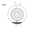
- Fig. 2 illustrates a residual state of the puncture repair liquid in a tire with a tread surface grounded.
- a reference numeral 1 denotes a pneumatic tire
- a reference numeral 2 denotes a wheel
- a reference numeral 3 denotes a tire valve mounted to the wheel
- a reference numeral 4 denotes puncture repair liquid injected in the pneumatic tire 1.
- an apparatus for recovering puncture repair liquid including a tube 10.
- the tube 10 is inserted through the tire valve 3 of the wheel 2 into the tire 1.
- the tube 10 includes an insertion portion 10a and a protruding portion 10b.
- the insertion portion 10a extends from the tire valve 3 to a liquid surface of the puncture repair liquid 4.
- the protruding portion 10b protrudes from the tire valve 3 to the outside of the tire 1.
- the tube 10, which includes these insertion portion 10a and protruding portion 10b, is formed as an integrally formed product.
- the tube 10 has a curved shape.
- the wheel 2 with the tire 1 within which the puncture repair liquid 4 has been injected is in a state that pressurized air is made to be filled in the tire 1.
- the tire 1 is grounded such that its central shaft may be horizontal.
- the tire 1 is disposed such that the tire valve 3 of the wheel 2 comes under the central shaft of the tire 1.
- a valve core is removed from the tire valve 3 of the wheel 2 in the arranged state. As illustrated in Figs.
- the tube 10 is inserted via the tire valve 3 up to the liquid surface of the puncture repair liquid 4, more preferably, up to the inner surface of the tire 1. This allows recovering the puncture repair liquid 4 in the tire 1 via the tube 10 using a residual pressure in the tire 1.
- the following measure is taken. With the valve core removed, the tire 1 may be filled with the pressurized air through the tire valve 3, and the pressurized air in the tire 1 may be discharged again through the tire valve 3.
- the puncture repair liquid 4 may be recovered to a container 20 with an appropriate capacity.
- the injection amount of the puncture repair liquid 4 is, for example, approximately 450 ml at a tire size of 195/65R15. Recovering the entire amount is not necessarily required. Recovering equal to or more than 75% of the entire amount can prevent the puncture repair liquid 4 from overflowing upon removal of the tire from a rim. Recovery time in this case is approximately 4 to 5 minutes.
- the puncture repair liquid 4 is preferably extracted from a tire with the tire removed from a vehicle after being temporarily repaired.
- the tire 1 Before starting the extraction work of the puncture repair liquid 4, the tire 1 is left for a while to deposit the puncture repair liquid 4 suspended in the upper portion of the tire 1 and a rim of the wheel 2 to a lower side.
- the shortest insertion amount of the tube 10 can be achieved by positioning the tire valve 3 at the lower side of the central shaft of the tire 1 to extract the puncture repair liquid 4.
- the distal end of the tube 10 needs to be in the puncture repair liquid 4. Accordingly, it is preferred that the puncture repair liquid 4 be extracted while confirming the presence of the puncture repair liquid 4 by rotating the tire 1 to right and left and inclining the tire 1 back and forth.
- the tube 10 can be increased in diameter as much as possible within an allowed range of the tire valve 3. This allows the puncture repair liquid 4 to be recovered in a short time based on a residual pressure in the tire 1. Accordingly, the puncture repair liquid 4 can be efficiently recovered without cutting off the tire valve 3.
- Figs. 3A and 3B illustrate a method for recovering puncture repair liquid according to another embodiment of the present invention.
- the puncture repair liquid 4 is injected in the tire 1, and the tire 1 with the wheel 2 where pressurized air is filled is grounded such that a central shaft O becomes horizontal.
- the tire 1 is arranged such that the tire valve 3 of the wheel 2 is located at a position shifted by 20 degrees or more, around the central shaft O of the tire 1, from a position P directly below the central shaft O (any position in a region X1).
- the tire 1 is arranged such that the tire valve 3 of the wheel 2 is located at a position shifted by 60 to 120 degrees, around the central shaft O of the tire 1, from the position P directly below the central shaft O (any position in a region X2).
- the valve core is removed from the tire valve 3.
- the tube 10 is inserted up to an inner surface of the tire 1 through the tire valve 3.
- the tire 1 is rolled such that the tire valve 3 comes to the position P directly below the central shaft O of the tire 1. This settles the distal end of the tube 10 in the puncture repair liquid 4, enabling recovery of the puncture repair liquid 4 in the tire 1 via the tube 10 using a residual pressure in the tire 1.
- the tube 10 is fully inserted up to the inner surface of the tire 1 in a state where the tire valve 3 is at a position laterally shifted to the tire 1. After that, the tire 1 is rolled such that the tire valve 3 comes to the position P directly below the central shaft O of the tire 1 to recover the puncture repair liquid 4. Therefore, the puncture repair liquid 4 is not discharged while the tube 10 is being inserted, making the work easy.
- the puncture repair liquid 4 may be abruptly discharged.
- the puncture repair liquid 4 is recovered while the tire 1 is grounded with the central shaft O horizontal; however, an arranged state of the tire 1 can be arbitrarily selected.
- the tire 1 is arranged such that the central shaft O is vertical.
- pressurized air in the tire 1 is discharged via the tire valve 3.
- the tube 10 is inserted through the tire valve 3 to bring the tube 10 to an inner surface of the tire 1 while the pressurized air in the tire 1 is being discharged.
- the tire 1 may be stood while the central shaft O becomes horizontal, and the tire valve 3 may be at the position P directly below the central shaft O of the tire 1 to bring the tube 10 to a liquid surface of the puncture repair liquid 4.
- Figs. 4 to 7B illustrate a tube employed in the present invention.
- a sealing portion 11 is formed in the middle of the tube 10.
- the sealing portion 11 has an outer diameter larger than the outer diameter of the tube 10 and can be fitted to the tire valve 3. More specifically, the sealing portion 11 is made of a pipe material thicker than the tube 10.
- the sealing portion 11 is slidably mounted in the longitudinal direction of the tube 10. Accordingly, the sealing portion 11 is slid along the longitudinal direction of the tube 10. This can adjust the length of the insertion portion 10a of the tube 10 according to the tire size. It is preferred that the sealing portion 11 be slidable with respect to the tube 10.
- the sealing portion 11 may be integrally formed with the tube 10.
- the tire valve 3 internally includes a cylindrically-shaped through hole 3a (shown by the dashed lines).
- the tire valve 3 also includes a narrow portion 3b at the base end side and a male thread portion 3c at the distal end side.
- the narrow portion 3b is to be engaged to a mounting hole of the wheel 2.
- the through hole 3a includes a thinnest portion 3d where a part of the through hole 3a is locally narrowed in the longitudinal direction and an inner diameter of the through hole 3a is narrowest.
- the outer diameter of the tube 10 is formed smaller than the inner diameter of the thinnest portion 3d of the through hole 3a of the tire valve 3.
- the outer diameter of the sealing portion 11 is formed larger than the inner diameter of the thinnest portion 3d of the through hole 3a of the tire valve 3.
- a small hole where the tube 10 is inserted is formed at the top portion of a cap 5 for tire valve. In the case where the cap 5 is tightened to the tire valve 3 with the tube 10 inserted into the tire valve 3 together with the sealing portion 1, the sealing portion 11 can be pressed into the tire valve 3 with the cap 5.
- the sealing portion 11 which has an outer diameter larger than the outer diameter of the tube 10 and can be fitted in the tire valve 3, is disposed in the middle of the tube 10. Further, to recover the puncture repair liquid 4 in the tire 1, the sealing portion 11 is fitted to the tire valve 3. This can prevent air leakage through a gap between the tube 10 and the tire valve 3, enabling efficient recovery of the puncture repair liquid 4. To enhance air tightness, the sealing portion 11 may have a wedge shape tapered off toward the tire valve 3.
- the material of the tube 10 is not especially limited. Materials such as rubber including silicone rubber, synthetic resin such as polypropylene, polyethylene, polyurethane, polyamide, and fluororesin, and a metal may be employed. Considering working efficiency in insertion of the tube 10, polyethylene and polyurethane are preferred.
- the length of a portion of the tube 10 inserted into the tire may be equal to or more than 150 mm, and is preferably within the range of 150 mm to 250 mm. This is because a proper length differs depending on tire size.
- the length of a portion of the tube 10 outside the tire is, considering working efficiently, preferred to be approximately 50 mm to 300 mm. Accordingly, the whole length of the tube 10 is approximately 200 mm to 550 mm. It is obvious for the tube 10 that the end portion of the tube in the tire is not inserted in an appropriate position if a portion inserted into the tire is short, and the same goes for the case where the portion inserted into the tire is too long. These cases make discharge of the puncture repair liquid 4 difficult.
- the outer diameter of the tube 10 be within the range of 2.5 mm to 3.0 mm. If the tube 10 is too thick, passing the tube 10 through the tire valve 3 is difficult. In contrast, if the tube 10 is too thin, discharge of the puncture repair liquid 4 takes much time. It is preferred that the inner diameter of the tube 10 be within the range of 50% to 90% of the outer diameter of the tube 10. This provides a certain amount of stiffness to the tube 10. Therefore, ease of insertion into the tire valve 3 is ensured while discharge efficiency of the puncture repair liquid 4 is enhanced. If the inner diameter of the tube 10 is too small, discharge efficiency of the puncture repair liquid 4 decreases. In contrast, if the inner diameter of the tube 10 is too large, the tube 10 becomes excessively flexible. These cases make insertion into the tire valve 3 difficult.
- the inner diameter of the tube 10 may be set within the range of 1.5 mm to 2.0 mm relative to the above-described outer diameter.
- the outer diameter of the sealing portion 11 be within the range of 3.2 mm to 4.0 mm. If the sealing portion 11 is too thick, pressing the sealing portion 11 into the tire valve 3 is difficult. In contrast, if the sealing portion 11 is too thin, ensuring air tightness is difficult.
- the tube 10 includes a ruler 12 that indicates the position of the sealing portion 11 by alphabetical letters A to C. Based on the ruler 12, the position of the sealing portion 11 is selected according to the tire size. That is, as the length of the tube 10, dimensions applicable to all assumed tires have been set. Appropriately selecting the position of the sealing portion 11 based on the ruler 12 allows application to various tire sizes.
- Fig. 6A illustrates the tube 10 on which the ruler 12 is directly indicated.
- Fig. 6B illustrates the ruler 12 printed on a sheet 13 made of a material such as paper. The sheet 13 on which the ruler 12 is printed may be a dedicated sheet. A part of an operating manual may be used.
- the definition of the ruler 12 is assumed to be described in the operating manual or similar medium.
- the operating manual describes a correspondence relationship between the alphabetical letters A to C on the ruler 12 and the tire sizes.
- the ruler 12 may indicate a tire size by employing different line thicknesses, different line colors, different numbers of lines, or similar specification.
- the ruler 12 may also indicate a tire size by numerals, signs, or similar characters instead of the above-described alphabetical letters.
- the tube 10 may include a ruler 12' indicating a cut length by alphabetical letters X to Z.
- the tube 10 may be cut off according to the tire size based on the ruler 12'. That is, as the length of the tube 10 before use, the dimensions where the tube 10 reaches from the tire valve 3 to an inner surface of the tire 1 have been set regarding all assumed tires. Appropriately cutting off the tube 10 based on the ruler 12' allows application to various tire sizes.
- Fig. 7A illustrates the tube 10 on which the ruler 12' is directly indicated.
- Fig. 7B illustrates the ruler 12' printed on a sheet 13' made of a material such as paper.
- the sheet 13' on which the ruler 12' is printed may be a dedicated sheet.
- a part of an operating manual may be used. In either case, the definition of the ruler 12' is assumed to be described in the operating manual or similar medium.
- the operating manual describes a correspondence relationship between the alphabetical letters X to Z on the ruler 12' and the tire sizes.
- the ruler 12' may indicate a tire size by employing different line thicknesses, different line colors, different numbers of lines, or similar specification.
- the ruler 12' may also indicate a tire size by numerals, signs, or similar characters instead of the above-described alphabetical letters.
- the constitution of the tube 10 is not especially limited.
- the tube 10 may be an integrally formed product that includes an insertion portion 10a and a protruding portion 10b.
- the insertion portion 10a extends from the tire valve 3 to an inner surface of the tire 1.
- the protruding portion 10b protrudes from the tire valve 3 to the outside of the tire 1.
- the tube 10 may be a member with which another pipe member is combined.
- Figs. 8 to 10 illustrate an assembly of the tube and the pipe member employed in the present invention.
- the tube 10 and a pipe member 15, which is thicker than the tube 10 are communicated with each other and coupled via a coupling member 16.
- the coupling member 16 includes, as illustrated in Fig. 9 , a cylindrically-shaped fixed portion 16a, a coupling portion 16b, and a cylindrically-shaped protrusion 16c.
- the cylindrically-shaped fixed portion 16a is engaged to and secured to the pipe member 15.
- the coupling portion 16b includes a female thread portion engaged to the tire valve 3.
- the cylindrically-shaped protrusion 16c holds the end portion of the tube 10.
- the cylindrically-shaped protrusion 16c is inserted into the tube 10.
- the tube 10 is inserted into the cylindrically-shaped protrusion 16c.
- the outer diameter of the cylindrically-shaped protrusion 16c needs to be smaller than the inner diameter of the tube 10, and therefore the flow rate of the puncture repair liquid 4 is reduced. In the latter case, the flow rate of the puncture repair liquid 4 is sufficiently ensured.
- a valve core is removed from the tire valve 3.
- the tube 10 is inserted via the tire valve 3 to bring the tube 10 to a liquid surface of the puncture repair liquid 4 while the air is being discharged through the tire valve 3.
- the coupling portion 16b of the coupling member 16 is engaged to the tire valve 3. This allows recovering the puncture repair liquid 4 in the tire 1 using a residual pressure in the tire 1 via the tube 10 and the pipe member 15.
- the tube 10 requires a length to be inserted through the tire valve 3 into the tire 1 at least to reach a liquid surface of the puncture repair liquid 4. Meanwhile, another member such as the pipe member 15 may be coupled outside the tire valve 3.
- the puncture repair liquid 4 is recovered via the tube 10.
- a flexible bag is applicable in addition to a bucket, a bottle, or similar member. It is preferred that the puncture repair liquid 4 be coagulated in the flexible bag with coagulant.
- Figs. 11 to 13 illustrate the flexible bag where coagulant employed in the present invention is sealed.
- the apparatus for recovering puncture repair liquid includes a coagulant 30 and a bag 40.
- the coagulant 30 coagulates the puncture repair liquid.
- the bag 40 has flexibility to house the puncture repair liquid.
- the coagulant 30 is not especially limited insofar as the coagulant 30 coagulates the puncture repair liquid that contains emulsion particles.
- the coagulant disclosed in JP-A-2009-41006 may be employed.
- This coagulant contains a mineral and a gelatinizing agent that cause the emulsion particles to aggregate.
- At least one kind of mineral selected from the group consisting of silicate, oxide, and carbonate is applicable.
- at least one kind of mineral selected from the group consisting of alumina, sodium silicate, magnesium silicate, aluminum silicate, montmorillonite, bentonite, and zeolite may be employed.
- a gelatinizing agent at least one kind of a gelatinizing agent selected from the group consisting of polyethylene oxide, polypropylene oxide, hydroxyethyl cellulose, and modified polymers thereof, alginate sodium, propylene glycol alginate, and dibenzylidene sorbitol may be employed.
- the amount of the gelatinizing agent may be 20 to 700 parts by weight. and is preferably 60 to 200 parts by weight. with respect to 100 parts by weight. of the mineral.
- the above-described coagulant can contain additive, for example, filler, age resister, oxidation inhibitor, pigment (dye), plasticizer, thixotropy-imparting agent, ultraviolet absorbing agent, flame-retardant agent, surfactant, dispersant, dehydrating agent, or antistatic agent as well as the mineral and the gelatinizing agent as necessary.
- the flexible bag 40 is formed by heat-sealing two side sheets 41 and 42 made of a laminated film 44 and one gusset 43 made of the laminated film 44 one another.
- the bag 40 includes preliminarily sealed coagulant 30. Further, it is preferred that the bag 40 have a capacity of 700 ml to 2000 ml to house the puncture repair liquid recovered from the tire.
- the gusset 43 is disposed at the lower portion of the bag 40. The gusset 43 is folded when not used; however, the gusset 43 may be always open. In either case, with the gusset 43 open, the bag 40 has a structure where a three-dimensional shape is formed and the bag 40 can stand alone.
- the laminated film 44 includes, as illustrated in Fig. 12 , a middle layer 44a, an inner layer 44b, and an outer layer 44c.
- the middle layer 44a has a gas barrier property.
- the inner layer 44b is laminated on the inner side of the middle layer 44a.
- the outer layer 44c is laminated on the outer side of the middle layer 44a.
- a metal foil such as aluminum foil is applicable in addition to a synthetic resin with low gas permeability such as ethylene vinyl alcohol copolymer (EVOH), polyamide (PA), polyvinylidene chloride (PVDC), polyvinyl alcohol (PVA), MX nylon (MXD6), and polyacrylonitrile resin (PAN).
- EVOH ethylene vinyl alcohol copolymer
- PA polyamide
- PVDC polyvinylidene chloride
- PVA polyvinyl alcohol
- MX nylon MX nylon
- PAN polyacrylonitrile resin
- the inner layer 44b and the outer layer 44c a synthetic resin such as polyethylene, polyester, and nylon are applicable to ensure mechanical strength and weather resistance. It is preferred that the inner layer 44b and the outer layer 44c be made of the same material. The inner layer 44b and the outer layer 44c may be made of mutually different materials according to required characteristics.
- the thickness of the middle layer 44a may be 5 ⁇ m to 200 ⁇ m. In the case of a metal foil such as aluminum foil, the thickness may be 1 nm to 500 nm, and is preferably 5 nm to 200 nm. If the middle layer 44a is too thin, this may cause reduction in the gas barrier property. In contrast, if the middle layer 44a is too thick, this may cause reduction in flexibility. Further, each thickness of the inner layer 44b and the outer layer 44c is preferably 5 ⁇ m to 100 ⁇ m. If the inner layer 44b and the outer layer 44c are too thin, durability when mixing the puncture repair liquid and the coagulant is reduced. Conversely, if the inner layer 44b and the outer layer 44c are too thick, the flexibility is reduced.
- Each of the inner layer 44b and the outer layer 44c may be a single layer or may be a plurality of layers made of different materials.
- the total thickness is preferably 5 ⁇ m to 100 ⁇ m.
- a notch 45 is disposed at the upper side edge portion of the bag 40.
- the upper end portion of the bag 40 is torn with this notch 45 set as a starting point.
- an opening 46 (see Fig. 13 ) is formed.
- the bag 40 includes a sealing belt 47 along the opening 46.
- the structure of the sealing belt 47 is not especially limited insofar as the sealing belt 47 can seal the opening 46.
- the sealing belt 47 can include a groove 47a at one side sheet 41 and a protrusion 47b at another side sheet 42.
- the groove 47a extends along the opening 46.
- the protrusion 47b extends along the opening 46 and elastically fits to the groove 47a.
- the upper end of the bag 40 containing the coagulant 30 is opened, and the puncture repair liquid 4 extracted from the tire 1 is put in the bag 40.
- the flexible bag 40 is crumpled to mix the puncture repair liquid 4 and the coagulant 30, thus the puncture repair liquid 4 is coagulated in the bag 40.
- the already-used puncture repair liquid 4 can be easily and smoothly disposed of together with the bag 40 as a combustible waste.
- the sealing belt 47 is disposed at the opening 46 of the flexible bag 40. This can surely prevent an overflow of the puncture repair liquid 4 upon crumpling the bag 40.
- the flexible bag 40 is constituted of the laminated film 44 including the middle layer 44a with a gas barrier property, and the coagulant 30 has been preliminary sealed in the bag 40. Therefore, the contained coagulant 30 is not exposed to the air, thus enabling maintaining the quality over a long period of time.
- the bag 40 has a structure with the gusset 43 at the lower portion so as to stand alone.
- the bag 40 need not be supported at the time of extracting the puncture repair liquid 4 from the tire 1. Accordingly, there is an advantage that all recovery work can be performed by one person even if an operation of a tube or similar is required when the puncture repair liquid 4 is extracted from the tire 1.
- a flexible bag that includes a laminated film, which includes a middle layer with a gas barrier property, and has preliminary sealed the coagulant inside the bag.
- a soft plastic bag or similar member may be employed as a flexible bag, and the coagulant may be sealed in another package with a gas barrier property. In that case, the coagulant and the puncture repair liquid may be simply put in the flexible bag together and then mixed.
Landscapes
- Engineering & Computer Science (AREA)
- Mechanical Engineering (AREA)
Abstract

Description
- The present invention relates to a method for recovering puncture repair liquid injected in a tire. More specifically, the present invention relates to a method for recovering puncture repair liquid that allows the efficient recovery of the puncture repair liquid without cutting off a tire valve.
- Recently, when a tire mounted to a vehicle is blown out, puncture repair liquid is injected in the tire via a tire valve. This temporarily repairs the puncture and fills the tire with air at the same time.
- However, with the above-described puncture repair method, the puncture repair liquid remains in the tire. When the tire is removed from a wheel for exchange, therefore, the puncture repair liquid overflows from the tire. This may cause inconvenience that a component such as a tire changer is contaminated.
- As a countermeasure against this problem, various methods to prevent overflow of the puncture repair liquid have been proposed. For example, the following have been proposed. Emulsion coagulant is injected in the tire where the puncture repair liquid remains. This solidifies the puncture repair liquid, and then the solidified product of the puncture repair liquid is disposed of after the tire is removed from the wheel (for example, see Patent Document 1). However, in this case, there is a drawback. Injection of the emulsion coagulant in the tire mounted to the wheel is difficult.
- Further, the following has been proposed. A tire valve is cut off from the wheel, a tube is inserted through a mounting hole of the tire valve into the tire so as to discharge the puncture repair liquid inside the tire via the tube (for example, see
Patent Documents 2 to 4). However, in this case, cutting off the tire valve is required, and a drawback arises in that the tire valve cannot be reused. - The following has also been proposed. A pipe that forms a gas flow passage and a pipe that forms a liquid flow passage are inserted into a tire valve. Pressurized air is introduced into the tire via the gas flow passage while puncture repair liquid is discharged to the outside of the tire via the liquid flow passage (for example, see Patent Document 5). However, in this case, it is necessary to insert the pipe that forms the gas flow passage and the pipe that forms the liquid flow passage into the tire valve; therefore, the liquid flow passage has to be extremely narrow. This creates a drawback that discharge of the puncture repair liquid takes much time.
-
- Patent Document 1:
JP-A-2009-41006 - Patent Document 2:
JP-A-2003-127242 - Patent Document 3:
JP-A-10-67212 - Patent Document 4:
U.S. Patent No. 5927348 - Patent Document 5:
JP-A-2007-331210 - It is an object of the present invention to provide a method for recovering puncture repair liquid that allows the efficient recovery of the puncture repair liquid without cutting off a tire valve.
- A method for recovering puncture repair liquid includes removing a valve core from the tire valve of the wheel with the tire where puncture repair liquid has been injected, discharging pressurized air filled in the tire via the tire valve, inserting the tube through the tire valve so as to bring the tube to a liquid surface of the puncture repair liquid while discharging the pressurized air in the tire, and recovering the puncture repair liquid in the tire via the tube using a residual pressure in the tire.
- In the present invention, a valve core is removed from a tire valve of a wheel with a tire where puncture repair liquid has been injected. Pressurized air filled in the tire is discharged via the tire valve. The tube is inserted through the tire valve so as to bring the tube to a liquid surface of the puncture repair liquid while discharging the pressurized air in the tire. The puncture repair liquid in the tire is recovered via the tube using a residual pressure in the tire. In this case, the tire valve does not have to be cut off. This allows using the tire valve intact after recovery of the puncture repair liquid. Additionally, the tube can be thickened as much as possible within an allowed range of the tire valve. This allows the puncture repair liquid to be recovered in a short time compared with the conventional structure where a pipe that forms a gas flow passage and a pipe that forms a liquid flow passage are inserted into a tire valve. Therefore, according to the present invention, the puncture repair liquid can efficiently be recovered without cutting off a tire valve. Furthermore, according to the present invention, there is an advantage that the apparatus for recovering puncture repair liquid need not be complicated and can be constituted with a small number of components.
- In the present invention, the following is preferred. The tube has an outer diameter smaller than an inner diameter of a thinnest portion of a through hole of the tire valve. The tube has an inner diameter within a range of 50% to 90% of the outer diameter thereof. Especially, it is preferred that the tube have an outer diameter within a range of 2.5 mm to 3.0 mm. This provides a certain amount of stiffness to the tube. Therefore, ease of insertion into the tire valve is ensured while discharge efficiency of the puncture repair liquid is enhanced.
- In the present invention, the tube is inserted through the tire valve into the tire while pressurized air in the tire is being discharged. Then, the tube may be brought to a liquid surface of the puncture repair liquid by changing an arranged state of the tire. In this case, insertion work of the tube is completed, and then the tube may be brought to a liquid surface of the puncture repair liquid by changing an arranged state of the tire so as to recover the puncture repair liquid. Therefore, the puncture repair liquid is not discharged while the tube is being inserted, making the work easy.
- More specifically, the following is preferred. The tire of a wheel where puncture repair liquid has been injected in the tire is grounded such that the central shaft becomes horizontal. The tire is arranged such that the tire valve of the wheel is located at a position shifted by 20 degrees or more, around the central shaft or the tire, from a position directly below the central shaft. Pressurized air in the tire is discharged via the tire valve in the arranged state. The tube is inserted through the tire valve into the tire while the pressurized air in the tire is being discharged. Then, the tube is brought to the liquid surface of the puncture repair liquid by rolling the tire such that the tire valve is at the position directly below the central shaft of the tire. Especially, it is preferred that the tire be arranged such that the tire valve is located at a position shifted by 60 to 120 degrees, around the central shaft of the tire, from the position directly below the central shaft at the time of insertion of the tube from the tire valve. In this case, insertion work of the tube is completed in a state where the tire valve is at a position shifted from the position directly below the central shaft of the tire. Then, the tube may be brought to the liquid surface of the puncture repair liquid by rolling the tire such that the tire valve is at the position directly below the central shaft of the tire to recover the puncture repair liquid. Therefore, the puncture repair liquid is not discharged while the tube is being inserted, making the work easy.
- Further, in the present invention, it is preferred that a coagulant to coagulate puncture repair liquid and a bag with flexibility to house the puncture repair liquid be employed. The puncture repair liquid extracted from the tire is put in the bag. The puncture repair liquid and the coagulant are mixed in the bag, and the congealed puncture repair liquid is recovered. As a result, the already-used puncture repair liquid can be easily and smoothly disposed of as a combustible waste. Objects, characteristics, aspects, and advantageous effects of the present invention will be clarified by referring to the description and the accompanying drawings below.
-
-
Figs. 1A and 1B are side views illustrating respective states where insertion amounts of a tube are varied regarding a method for recovering puncture repair liquid according to an embodiment of the present invention. -
Fig. 2 is a front view illustrating a residual state of puncture repair liquid in a tire in a state where a tread surface is grounded. -
Figs. 3A and 3B are front views illustrating respective states where rotation positions of the tires are varied regarding a method for recovering puncture repair liquid according to another embodiment of the present invention. -
Fig. 4 is a side view illustrating an exemplary tube employed in the present invention. -
Fig. 5 is a side view illustrating a state where the tube employed in the present invention is inserted into a tire valve. -
Figs. 6A and 6B are side views illustrating an example of the main portion of the respective tubes employed in the present invention. -
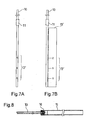
Figs. 7A and 7B are side views illustrating an example of the main portion of the respective tubes employed in the present invention. -
Fig. 8 is a side view illustrating an assembly of the tube and a pipe member employed in the present invention. -
Fig. 9 is an enlarged cross-sectional view illustrating a coupling structure of the tube and the pipe member inFig. 8 . -
Fig. 10 is a cross-sectional view illustrating a modification of the coupling structure of the tube and the pipe member inFig. 8 . -
Fig. 11 is a side view illustrating a partially cutout bag with flexibility where a coagulant employed in the present invention is sealed. -
Fig. 12 is an enlarged cross-sectional view illustrating a laminated film constituting the bag ofFig. 11 . -
Fig. 13 is a perspective view illustrating the bag ofFig. 11 in use. - A detailed description will be given of a constitution of embodiments of the present invention with reference to the attached drawings.
Figs. 1A and 1B illustrate a method for recovering puncture repair liquid according to the embodiment of the present invention.Fig. 2 illustrates a residual state of the puncture repair liquid in a tire with a tread surface grounded. InFigs. 1A and 1B andFig. 2 , areference numeral 1 denotes a pneumatic tire, areference numeral 2 denotes a wheel, areference numeral 3 denotes a tire valve mounted to the wheel, and areference numeral 4 denotes puncture repair liquid injected in thepneumatic tire 1. - As illustrated in
Figs. 1A and 1B , with a method for recovering puncture repair liquid according to this embodiment, there is employed an apparatus for recovering puncture repair liquid including atube 10. Thetube 10 is inserted through thetire valve 3 of thewheel 2 into thetire 1. Thetube 10 includes aninsertion portion 10a and a protrudingportion 10b. Theinsertion portion 10a extends from thetire valve 3 to a liquid surface of thepuncture repair liquid 4. The protrudingportion 10b protrudes from thetire valve 3 to the outside of thetire 1. Thetube 10, which includes theseinsertion portion 10a and protrudingportion 10b, is formed as an integrally formed product. Thetube 10 has a curved shape. - To recover the puncture repair liquid using the apparatus for recovering puncture repair liquid like this, first, the
wheel 2 with thetire 1 within which thepuncture repair liquid 4 has been injected is in a state that pressurized air is made to be filled in thetire 1. Next, thetire 1 is grounded such that its central shaft may be horizontal. Thetire 1 is disposed such that thetire valve 3 of thewheel 2 comes under the central shaft of thetire 1. Then, a valve core is removed from thetire valve 3 of thewheel 2 in the arranged state. As illustrated inFigs. 1A and 1B , while the pressurized air in thetire 1 is being discharged through thetire valve 3, thetube 10 is inserted via thetire valve 3 up to the liquid surface of thepuncture repair liquid 4, more preferably, up to the inner surface of thetire 1. This allows recovering thepuncture repair liquid 4 in thetire 1 via thetube 10 using a residual pressure in thetire 1. In the case where thetube 10 cannot be inserted while the pressurized air in thetire 1 is being discharged, the following measure is taken. With the valve core removed, thetire 1 may be filled with the pressurized air through thetire valve 3, and the pressurized air in thetire 1 may be discharged again through thetire valve 3. - In the above-described extraction work of the
puncture repair liquid 4, rotation of thecurved tube 10 around its axis allows appropriately adjusting the distal end position of thetube 10 and efficiently absorbing thepuncture repair liquid 4. Thepuncture repair liquid 4 may be recovered to acontainer 20 with an appropriate capacity. The injection amount of thepuncture repair liquid 4 is, for example, approximately 450 ml at a tire size of 195/65R15. Recovering the entire amount is not necessarily required. Recovering equal to or more than 75% of the entire amount can prevent thepuncture repair liquid 4 from overflowing upon removal of the tire from a rim. Recovery time in this case is approximately 4 to 5 minutes. - The
puncture repair liquid 4 is preferably extracted from a tire with the tire removed from a vehicle after being temporarily repaired. Before starting the extraction work of thepuncture repair liquid 4, thetire 1 is left for a while to deposit thepuncture repair liquid 4 suspended in the upper portion of thetire 1 and a rim of thewheel 2 to a lower side. The shortest insertion amount of thetube 10 can be achieved by positioning thetire valve 3 at the lower side of the central shaft of thetire 1 to extract thepuncture repair liquid 4. To extract thepuncture repair liquid 4, the distal end of thetube 10 needs to be in thepuncture repair liquid 4. Accordingly, it is preferred that thepuncture repair liquid 4 be extracted while confirming the presence of thepuncture repair liquid 4 by rotating thetire 1 to right and left and inclining thetire 1 back and forth. - According to the above-described method for recovering puncture repair liquid, during the recovery of the
puncture repair liquid 4 in thetire 1, cutting off thetire valve 3 is not required. This allows using thetire valve 3 intact after recovery of thepuncture repair liquid 4. Additionally, thetube 10 can be increased in diameter as much as possible within an allowed range of thetire valve 3. This allows thepuncture repair liquid 4 to be recovered in a short time based on a residual pressure in thetire 1. Accordingly, thepuncture repair liquid 4 can be efficiently recovered without cutting off thetire valve 3. -
Figs. 3A and 3B illustrate a method for recovering puncture repair liquid according to another embodiment of the present invention. In this embodiment, first, as illustrated inFig. 3A , thepuncture repair liquid 4 is injected in thetire 1, and thetire 1 with thewheel 2 where pressurized air is filled is grounded such that a central shaft O becomes horizontal. Then, thetire 1 is arranged such that thetire valve 3 of thewheel 2 is located at a position shifted by 20 degrees or more, around the central shaft O of thetire 1, from a position P directly below the central shaft O (any position in a region X1). More preferably, thetire 1 is arranged such that thetire valve 3 of thewheel 2 is located at a position shifted by 60 to 120 degrees, around the central shaft O of thetire 1, from the position P directly below the central shaft O (any position in a region X2). In this arranged state, the valve core is removed from thetire valve 3. While air is being discharged through thetire valve 3, thetube 10 is inserted up to an inner surface of thetire 1 through thetire valve 3. Then, as illustrated inFig. 3B , thetire 1 is rolled such that thetire valve 3 comes to the position P directly below the central shaft O of thetire 1. This settles the distal end of thetube 10 in thepuncture repair liquid 4, enabling recovery of thepuncture repair liquid 4 in thetire 1 via thetube 10 using a residual pressure in thetire 1. - If an operation such as the above-described operation is performed, the
tube 10 is fully inserted up to the inner surface of thetire 1 in a state where thetire valve 3 is at a position laterally shifted to thetire 1. After that, thetire 1 is rolled such that thetire valve 3 comes to the position P directly below the central shaft O of thetire 1 to recover thepuncture repair liquid 4. Therefore, thepuncture repair liquid 4 is not discharged while thetube 10 is being inserted, making the work easy. Here, if thetire valve 3 is too close to the position P directly below the central shaft O of thetire 1 at the time of insertion of thetube 10 through thetire valve 3, thepuncture repair liquid 4 may be abruptly discharged. In contrast, if thetire valve 3 is too far from the position P directly below the central shaft O of thetire 1, thepuncture repair liquid 4 drops on the rim of thewheel 2 along with rotation of thetire 1 and is difficult to accumulate in the lower side. These may cause insufficient recovery of thepuncture repair liquid 4. - In the above-described embodiments, a description has been given in the case where the
puncture repair liquid 4 is recovered while thetire 1 is grounded with the central shaft O horizontal; however, an arranged state of thetire 1 can be arbitrarily selected. For example, thetire 1 is arranged such that the central shaft O is vertical. In the arranged state, pressurized air in thetire 1 is discharged via thetire valve 3. Thetube 10 is inserted through thetire valve 3 to bring thetube 10 to an inner surface of thetire 1 while the pressurized air in thetire 1 is being discharged. Then, thetire 1 may be stood while the central shaft O becomes horizontal, and thetire valve 3 may be at the position P directly below the central shaft O of thetire 1 to bring thetube 10 to a liquid surface of thepuncture repair liquid 4. -
Figs. 4 to 7B illustrate a tube employed in the present invention. As illustrated inFig. 4 , a sealingportion 11 is formed in the middle of thetube 10. The sealingportion 11 has an outer diameter larger than the outer diameter of thetube 10 and can be fitted to thetire valve 3. More specifically, the sealingportion 11 is made of a pipe material thicker than thetube 10. The sealingportion 11 is slidably mounted in the longitudinal direction of thetube 10. Accordingly, the sealingportion 11 is slid along the longitudinal direction of thetube 10. This can adjust the length of theinsertion portion 10a of thetube 10 according to the tire size. It is preferred that the sealingportion 11 be slidable with respect to thetube 10. The sealingportion 11 may be integrally formed with thetube 10. - As illustrated in
Fig. 5 , thetire valve 3 internally includes a cylindrically-shaped throughhole 3a (shown by the dashed lines). Thetire valve 3 also includes anarrow portion 3b at the base end side and amale thread portion 3c at the distal end side. Thenarrow portion 3b is to be engaged to a mounting hole of thewheel 2. The throughhole 3a includes athinnest portion 3d where a part of the throughhole 3a is locally narrowed in the longitudinal direction and an inner diameter of the throughhole 3a is narrowest. During internal pressurization, a valve core is inserted into thetire valve 3. - Considering the structure of the above-described
tire valve 3, the outer diameter of thetube 10 is formed smaller than the inner diameter of thethinnest portion 3d of the throughhole 3a of thetire valve 3. The outer diameter of the sealingportion 11 is formed larger than the inner diameter of thethinnest portion 3d of the throughhole 3a of thetire valve 3. At the top portion of acap 5 for tire valve, a small hole where thetube 10 is inserted is formed. In the case where thecap 5 is tightened to thetire valve 3 with thetube 10 inserted into thetire valve 3 together with the sealingportion 1, the sealingportion 11 can be pressed into thetire valve 3 with thecap 5. - Thus, the sealing
portion 11, which has an outer diameter larger than the outer diameter of thetube 10 and can be fitted in thetire valve 3, is disposed in the middle of thetube 10. Further, to recover thepuncture repair liquid 4 in thetire 1, the sealingportion 11 is fitted to thetire valve 3. This can prevent air leakage through a gap between thetube 10 and thetire valve 3, enabling efficient recovery of thepuncture repair liquid 4. To enhance air tightness, the sealingportion 11 may have a wedge shape tapered off toward thetire valve 3. - The material of the
tube 10 is not especially limited. Materials such as rubber including silicone rubber, synthetic resin such as polypropylene, polyethylene, polyurethane, polyamide, and fluororesin, and a metal may be employed. Considering working efficiency in insertion of thetube 10, polyethylene and polyurethane are preferred. - The length of a portion of the
tube 10 inserted into the tire may be equal to or more than 150 mm, and is preferably within the range of 150 mm to 250 mm. This is because a proper length differs depending on tire size. The length of a portion of thetube 10 outside the tire is, considering working efficiently, preferred to be approximately 50 mm to 300 mm. Accordingly, the whole length of thetube 10 is approximately 200 mm to 550 mm. It is obvious for thetube 10 that the end portion of the tube in the tire is not inserted in an appropriate position if a portion inserted into the tire is short, and the same goes for the case where the portion inserted into the tire is too long. These cases make discharge of thepuncture repair liquid 4 difficult. - It is preferred that the outer diameter of the
tube 10 be within the range of 2.5 mm to 3.0 mm. If thetube 10 is too thick, passing thetube 10 through thetire valve 3 is difficult. In contrast, if thetube 10 is too thin, discharge of thepuncture repair liquid 4 takes much time. It is preferred that the inner diameter of thetube 10 be within the range of 50% to 90% of the outer diameter of thetube 10. This provides a certain amount of stiffness to thetube 10. Therefore, ease of insertion into thetire valve 3 is ensured while discharge efficiency of thepuncture repair liquid 4 is enhanced. If the inner diameter of thetube 10 is too small, discharge efficiency of thepuncture repair liquid 4 decreases. In contrast, if the inner diameter of thetube 10 is too large, thetube 10 becomes excessively flexible. These cases make insertion into thetire valve 3 difficult. For example, the inner diameter of thetube 10 may be set within the range of 1.5 mm to 2.0 mm relative to the above-described outer diameter. - On the other hand, it is preferred that the outer diameter of the sealing
portion 11 be within the range of 3.2 mm to 4.0 mm. If the sealingportion 11 is too thick, pressing the sealingportion 11 into thetire valve 3 is difficult. In contrast, if the sealingportion 11 is too thin, ensuring air tightness is difficult. - As illustrated in
Figs. 6A and 6B , thetube 10 includes aruler 12 that indicates the position of the sealingportion 11 by alphabetical letters A to C. Based on theruler 12, the position of the sealingportion 11 is selected according to the tire size. That is, as the length of thetube 10, dimensions applicable to all assumed tires have been set. Appropriately selecting the position of the sealingportion 11 based on theruler 12 allows application to various tire sizes.Fig. 6A illustrates thetube 10 on which theruler 12 is directly indicated.Fig. 6B illustrates theruler 12 printed on asheet 13 made of a material such as paper. Thesheet 13 on which theruler 12 is printed may be a dedicated sheet. A part of an operating manual may be used. In either case, the definition of theruler 12 is assumed to be described in the operating manual or similar medium. For example, the operating manual describes a correspondence relationship between the alphabetical letters A to C on theruler 12 and the tire sizes. Theruler 12 may indicate a tire size by employing different line thicknesses, different line colors, different numbers of lines, or similar specification. Theruler 12 may also indicate a tire size by numerals, signs, or similar characters instead of the above-described alphabetical letters. - As described above, instead of changing the position of the sealing
portion 11, as illustrated inFigs. 7A and 7B , thetube 10 may include a ruler 12' indicating a cut length by alphabetical letters X to Z. Thetube 10 may be cut off according to the tire size based on the ruler 12'. That is, as the length of thetube 10 before use, the dimensions where thetube 10 reaches from thetire valve 3 to an inner surface of thetire 1 have been set regarding all assumed tires. Appropriately cutting off thetube 10 based on the ruler 12' allows application to various tire sizes.Fig. 7A illustrates thetube 10 on which the ruler 12' is directly indicated.Fig. 7B illustrates the ruler 12' printed on a sheet 13' made of a material such as paper. The sheet 13' on which the ruler 12' is printed may be a dedicated sheet. A part of an operating manual may be used. In either case, the definition of the ruler 12' is assumed to be described in the operating manual or similar medium. For example, the operating manual describes a correspondence relationship between the alphabetical letters X to Z on the ruler 12' and the tire sizes. The ruler 12' may indicate a tire size by employing different line thicknesses, different line colors, different numbers of lines, or similar specification. The ruler 12' may also indicate a tire size by numerals, signs, or similar characters instead of the above-described alphabetical letters. - With the above-described method for recovering puncture repair liquid, the constitution of the
tube 10 is not especially limited. For example, as illustrated inFig. 4 , thetube 10 may be an integrally formed product that includes aninsertion portion 10a and a protrudingportion 10b. Theinsertion portion 10a extends from thetire valve 3 to an inner surface of thetire 1. The protrudingportion 10b protrudes from thetire valve 3 to the outside of thetire 1. Additionally, thetube 10 may be a member with which another pipe member is combined. -
Figs. 8 to 10 illustrate an assembly of the tube and the pipe member employed in the present invention. As illustrated inFig. 8 , thetube 10 and apipe member 15, which is thicker than thetube 10, are communicated with each other and coupled via acoupling member 16. Thecoupling member 16 includes, as illustrated inFig. 9 , a cylindrically-shapedfixed portion 16a, acoupling portion 16b, and a cylindrically-shapedprotrusion 16c. The cylindrically-shapedfixed portion 16a is engaged to and secured to thepipe member 15. Thecoupling portion 16b includes a female thread portion engaged to thetire valve 3. The cylindrically-shapedprotrusion 16c holds the end portion of thetube 10. In the example inFig. 9 , the cylindrically-shapedprotrusion 16c is inserted into thetube 10. In the example inFig. 10 , thetube 10 is inserted into the cylindrically-shapedprotrusion 16c. In the former case, the outer diameter of the cylindrically-shapedprotrusion 16c needs to be smaller than the inner diameter of thetube 10, and therefore the flow rate of thepuncture repair liquid 4 is reduced. In the latter case, the flow rate of thepuncture repair liquid 4 is sufficiently ensured. - To employ the above-described assembly including the
tube 10 and thepipe member 15, a valve core is removed from thetire valve 3. Thetube 10 is inserted via thetire valve 3 to bring thetube 10 to a liquid surface of thepuncture repair liquid 4 while the air is being discharged through thetire valve 3. Thecoupling portion 16b of thecoupling member 16 is engaged to thetire valve 3. This allows recovering thepuncture repair liquid 4 in thetire 1 using a residual pressure in thetire 1 via thetube 10 and thepipe member 15. - Thus, the
tube 10 requires a length to be inserted through thetire valve 3 into thetire 1 at least to reach a liquid surface of thepuncture repair liquid 4. Meanwhile, another member such as thepipe member 15 may be coupled outside thetire valve 3. - With the above-described embodiments, the
puncture repair liquid 4 is recovered via thetube 10. As a recovery container, a flexible bag is applicable in addition to a bucket, a bottle, or similar member. It is preferred that thepuncture repair liquid 4 be coagulated in the flexible bag with coagulant. -
Figs. 11 to 13 illustrate the flexible bag where coagulant employed in the present invention is sealed. As illustrated inFig. 11 , the apparatus for recovering puncture repair liquid according to the present embodiment includes acoagulant 30 and abag 40. Thecoagulant 30 coagulates the puncture repair liquid. Thebag 40 has flexibility to house the puncture repair liquid. - The
coagulant 30 is not especially limited insofar as thecoagulant 30 coagulates the puncture repair liquid that contains emulsion particles. For example, the coagulant disclosed inJP-A-2009-41006 - As the above-described mineral, at least one kind of mineral selected from the group consisting of silicate, oxide, and carbonate is applicable. For example, as the mineral, at least one kind of mineral selected from the group consisting of alumina, sodium silicate, magnesium silicate, aluminum silicate, montmorillonite, bentonite, and zeolite may be employed.
- On the other hand, as a gelatinizing agent, at least one kind of a gelatinizing agent selected from the group consisting of polyethylene oxide, polypropylene oxide, hydroxyethyl cellulose, and modified polymers thereof, alginate sodium, propylene glycol alginate, and dibenzylidene sorbitol may be employed.
- The amount of the gelatinizing agent may be 20 to 700 parts by weight. and is preferably 60 to 200 parts by weight. with respect to 100 parts by weight. of the mineral. However, the above-described coagulant can contain additive, for example, filler, age resister, oxidation inhibitor, pigment (dye), plasticizer, thixotropy-imparting agent, ultraviolet absorbing agent, flame-retardant agent, surfactant, dispersant, dehydrating agent, or antistatic agent as well as the mineral and the gelatinizing agent as necessary.
- On the other hand, the
flexible bag 40 is formed by heat-sealing twoside sheets gusset 43 made of the laminated film 44 one another. Thebag 40 includes preliminarily sealedcoagulant 30. Further, it is preferred that thebag 40 have a capacity of 700 ml to 2000 ml to house the puncture repair liquid recovered from the tire. Thegusset 43 is disposed at the lower portion of thebag 40. Thegusset 43 is folded when not used; however, thegusset 43 may be always open. In either case, with thegusset 43 open, thebag 40 has a structure where a three-dimensional shape is formed and thebag 40 can stand alone. - The laminated film 44 includes, as illustrated in
Fig. 12 , a middle layer 44a, an inner layer 44b, and an outer layer 44c. The middle layer 44a has a gas barrier property. The inner layer 44b is laminated on the inner side of the middle layer 44a. The outer layer 44c is laminated on the outer side of the middle layer 44a. As a material constituting the middle layer 44a, a metal foil such as aluminum foil is applicable in addition to a synthetic resin with low gas permeability such as ethylene vinyl alcohol copolymer (EVOH), polyamide (PA), polyvinylidene chloride (PVDC), polyvinyl alcohol (PVA), MX nylon (MXD6), and polyacrylonitrile resin (PAN). On the other hand, as a material constituting the inner layer 44b and the outer layer 44c, a synthetic resin such as polyethylene, polyester, and nylon are applicable to ensure mechanical strength and weather resistance. It is preferred that the inner layer 44b and the outer layer 44c be made of the same material. The inner layer 44b and the outer layer 44c may be made of mutually different materials according to required characteristics. - In the case of synthetic resin, the thickness of the middle layer 44a may be 5 µm to 200 µm. In the case of a metal foil such as aluminum foil, the thickness may be 1 nm to 500 nm, and is preferably 5 nm to 200 nm. If the middle layer 44a is too thin, this may cause reduction in the gas barrier property. In contrast, if the middle layer 44a is too thick, this may cause reduction in flexibility. Further, each thickness of the inner layer 44b and the outer layer 44c is preferably 5 µm to 100 µm. If the inner layer 44b and the outer layer 44c are too thin, durability when mixing the puncture repair liquid and the coagulant is reduced. Conversely, if the inner layer 44b and the outer layer 44c are too thick, the flexibility is reduced.
- Each of the inner layer 44b and the outer layer 44c may be a single layer or may be a plurality of layers made of different materials. For the plurality of layers, the total thickness is preferably 5 µm to 100 µm.
- A
notch 45 is disposed at the upper side edge portion of thebag 40. The upper end portion of thebag 40 is torn with thisnotch 45 set as a starting point. Thus, an opening 46 (seeFig. 13 ) is formed. Thebag 40 includes a sealingbelt 47 along the opening 46. The structure of the sealingbelt 47 is not especially limited insofar as the sealingbelt 47 can seal the opening 46. For example, the sealingbelt 47 can include a groove 47a at oneside sheet 41 and aprotrusion 47b at anotherside sheet 42. The groove 47a extends along the opening 46. Theprotrusion 47b extends along the opening 46 and elastically fits to the groove 47a. - To recover the
puncture repair liquid 4 using the above-describedcoagulant 30 andbag 40, as illustrated inFig. 13 , the upper end of thebag 40 containing thecoagulant 30 is opened, and thepuncture repair liquid 4 extracted from thetire 1 is put in thebag 40. Next, after the opening 46 of thebag 40 is sealed with the sealingbelt 47, theflexible bag 40 is crumpled to mix thepuncture repair liquid 4 and thecoagulant 30, thus thepuncture repair liquid 4 is coagulated in thebag 40. As a result, the already-usedpuncture repair liquid 4 can be easily and smoothly disposed of together with thebag 40 as a combustible waste. - With the above-described method for recovering puncture repair liquid, the sealing
belt 47 is disposed at the opening 46 of theflexible bag 40. This can surely prevent an overflow of thepuncture repair liquid 4 upon crumpling thebag 40. - Additionally, the
flexible bag 40 is constituted of the laminated film 44 including the middle layer 44a with a gas barrier property, and thecoagulant 30 has been preliminary sealed in thebag 40. Therefore, the containedcoagulant 30 is not exposed to the air, thus enabling maintaining the quality over a long period of time. - Further, the
bag 40 has a structure with thegusset 43 at the lower portion so as to stand alone. Thebag 40 need not be supported at the time of extracting thepuncture repair liquid 4 from thetire 1. Accordingly, there is an advantage that all recovery work can be performed by one person even if an operation of a tube or similar is required when thepuncture repair liquid 4 is extracted from thetire 1. - The above-described embodiment has been described using a flexible bag that includes a laminated film, which includes a middle layer with a gas barrier property, and has preliminary sealed the coagulant inside the bag. In the present invention, a soft plastic bag or similar member may be employed as a flexible bag, and the coagulant may be sealed in another package with a gas barrier property. In that case, the coagulant and the puncture repair liquid may be simply put in the flexible bag together and then mixed.
- This application is based on Japanese Patent Application No.
2010-259493 filed on November 19, 2010 JP-A-2009-41006 JP-A-2003-127242 JP-A-10-67212 U.S. Patent No. 5927348 , andJP-A-2007-331210 - The above description of a specific embodiment of the present invention is disclosed as illustrative. This does not intend to be exhaustive or limit the present invention to the described embodiments as they are. Many modifications and variations will be apparent to one of ordinary skill in the art in light of the above teachings.
-
- 1
- pneumatic tire
- 2
- wheel
- 3
- tire valve
- 4
- puncture repair liquid
- 5
- cap
- 10
- tube
- 11
- sealing portion
- 12, 12'
- ruler
- 13, 13'
- sheet
- 20
- container
- 30
- coagulant
- 40
- bag
Claims (7)
- A method for recovering puncture repair liquid, comprising:preparing a tube to be inserted into a tire through a tire valve mounted to a wheel;removing a valve core from the tire valve of the wheel with the tire where puncture repair liquid has been injected;discharging, through the tire valve, pressurized air filled in the tire;inserting the tube through the tire valve so as to bring the tube to a liquid surface of the puncture repair liquid while discharging the pressurized air in the tire; andrecovering the puncture repair liquid in the tire via the inserted tube using a residual pressure in the tire.
- The method for recovering puncture repair liquid according to claim 1, wherein
as the tube, a tube that has an outer diameter smaller than an inner diameter of a thinnest portion of a through hole of the tire valve and has an inner diameter within a range of 50% to 90% of the outer diameter is prepared. - The method for recovering puncture repair liquid according to claim 2, wherein
as the tube, a tube that has an outer diameter within a range of 2.5 mm to 3.0 mm is prepared. - The method for recovering puncture repair liquid according to any of claims 1 to 3, wherein
the inserting the tube includes:inserting the tube through the tire valve into the tire while the pressurized air in the tire is being discharged; andbringing the tube to a liquid surface of the puncture repair liquid by changing an arranged state of the tire after the insertion. - The method for recovering puncture repair liquid according to any of claims 1 to 3, further comprising:grounding the tire of the wheel where the puncture repair liquid has been injected in the tire such that a central shaft of the tire becomes horizontal; andarranging the tire such that the tire valve of the grounded wheel is located at a position shifted by 20 degrees or more, around the central shaft of the tire, from a position directly below the central shaft, whereinthe discharging the pressurized air via the tire valve includes discharging the pressurized air in the arranged tire via the tire valve,the inserting the tube includes:inserting the tube through the tire valve into the tire while the pressurized air in the tire is being discharged; andbringing the tube to the liquid surface of the puncture repair liquid by rolling the tire after the insertion such that the tire valve is at the position directly below the central shaft of the tire.
- The method for recovering puncture repair liquid according to claim 5, wherein
the arranging the tire includes arranging the tire such that the tire valve is located at a position shifted by 60 to 120 degrees, around the central shaft of the tire, from the position directly below the central shaft of when inserting the tube through the tire valve. - The method for recovering puncture repair liquid according to any of claims 1 to 6, further comprising:preparing a coagulant to coagulate puncture repair liquid; andpreparing a bag with flexibility to house the puncture repair liquid, whereinthe recovering puncture repair liquid includes recovering the puncture repair liquid in a coagulated state, the puncture repair liquid being coagulated by putting puncture repair liquid extracted from the tire into the bag, and mixing the puncture repair liquid and the coagulant in the bag.
Applications Claiming Priority (2)
| Application Number | Priority Date | Filing Date | Title |
|---|---|---|---|
| JP2010259493A JP5177208B2 (en) | 2010-11-19 | 2010-11-19 | How to recover puncture repair liquid |
| PCT/JP2011/063223 WO2012066812A1 (en) | 2010-11-19 | 2011-06-09 | Method for recovering puncture repair solution |
Publications (3)
| Publication Number | Publication Date |
|---|---|
| EP2641728A1 true EP2641728A1 (en) | 2013-09-25 |
| EP2641728A4 EP2641728A4 (en) | 2014-08-06 |
| EP2641728B1 EP2641728B1 (en) | 2018-08-22 |
Family
ID=46083757
Family Applications (1)
| Application Number | Title | Priority Date | Filing Date |
|---|---|---|---|
| EP11840959.8A Active EP2641728B1 (en) | 2010-11-19 | 2011-06-09 | Method for recovering puncture repair solution |
Country Status (7)
| Country | Link |
|---|---|
| US (1) | US8826946B2 (en) |
| EP (1) | EP2641728B1 (en) |
| JP (1) | JP5177208B2 (en) |
| KR (1) | KR101780525B1 (en) |
| CN (1) | CN103221202B (en) |
| RU (1) | RU2536147C1 (en) |
| WO (1) | WO2012066812A1 (en) |
Families Citing this family (1)
| Publication number | Priority date | Publication date | Assignee | Title |
|---|---|---|---|---|
| CN113524733A (en) * | 2020-04-13 | 2021-10-22 | 阿米瑟工业股份有限公司 | Suction pipe device of tire air valve |
Family Cites Families (16)
| Publication number | Priority date | Publication date | Assignee | Title |
|---|---|---|---|---|
| US4700531A (en) * | 1984-07-20 | 1987-10-20 | American Can Company | Method of forming a package having strong seals and a modified ply-separation opening |
| DE19625372B4 (en) | 1996-06-25 | 2006-05-24 | Sumitomo Rubber Industries Ltd., Kobe | Method of removing puncture sealants from tires and apparatus for carrying out the method |
| JPH11222244A (en) * | 1998-02-02 | 1999-08-17 | Hosokawa Yoko:Kk | Pharmaceutical and medical gusset bags |
| JP2002166713A (en) | 2000-12-04 | 2002-06-11 | Sumitomo Rubber Ind Ltd | Container for puncture sealant and puncture repair system using the same |
| JP3782333B2 (en) | 2001-10-22 | 2006-06-07 | 住友ゴム工業株式会社 | Sealing agent injection / extraction hose and tire repair method using the same |
| US7658543B2 (en) * | 2002-04-17 | 2010-02-09 | Toppan Printing Co., Ltd. | Packaging material and packaging bag |
| JP3782385B2 (en) * | 2002-09-26 | 2006-06-07 | 住友ゴム工業株式会社 | Sealing agent injection / extraction hose set |
| JP2005138400A (en) * | 2003-11-06 | 2005-06-02 | Bridgestone Corp | Sealant recovery apparatus |
| JP4320609B2 (en) * | 2004-03-30 | 2009-08-26 | 栗田工業株式会社 | Purification method of contaminated groundwater |
| CA2570848A1 (en) * | 2004-06-15 | 2006-01-05 | Glendon C. Daly | Tire sealant |
| US9555931B2 (en) * | 2006-06-07 | 2017-01-31 | Reynolds Consumer Products LLC | Slider bag with handle below the zipper track |
| JP2007331210A (en) * | 2006-06-14 | 2007-12-27 | Bridgestone Corp | Device for recovering sealant |
| JP4245654B2 (en) | 2007-07-17 | 2009-03-25 | 横浜ゴム株式会社 | Emulsion coagulant |
| JP2009090862A (en) * | 2007-10-10 | 2009-04-30 | Bridgestone Corp | Tire/rim assembly, tire valve, and sealant recovering method |
| JP2009090574A (en) * | 2007-10-10 | 2009-04-30 | Bridgestone Corp | Method for collecting sealing agent |
| JP2010259493A (en) | 2009-04-30 | 2010-11-18 | Yozo Shinozaki | Fastener |
-
2010
- 2010-11-19 JP JP2010259493A patent/JP5177208B2/en active Active
-
2011
- 2011-06-09 RU RU2013127650/05A patent/RU2536147C1/en active
- 2011-06-09 KR KR1020137015710A patent/KR101780525B1/en not_active Expired - Fee Related
- 2011-06-09 WO PCT/JP2011/063223 patent/WO2012066812A1/en not_active Ceased
- 2011-06-09 US US13/885,969 patent/US8826946B2/en active Active
- 2011-06-09 EP EP11840959.8A patent/EP2641728B1/en active Active
- 2011-06-09 CN CN201180055105.1A patent/CN103221202B/en active Active
Also Published As
| Publication number | Publication date |
|---|---|
| KR101780525B1 (en) | 2017-09-21 |
| KR20130116292A (en) | 2013-10-23 |
| CN103221202A (en) | 2013-07-24 |
| US20130233405A1 (en) | 2013-09-12 |
| US8826946B2 (en) | 2014-09-09 |
| CN103221202B (en) | 2016-01-20 |
| JP5177208B2 (en) | 2013-04-03 |
| EP2641728B1 (en) | 2018-08-22 |
| EP2641728A4 (en) | 2014-08-06 |
| JP2012111055A (en) | 2012-06-14 |
| RU2536147C1 (en) | 2014-12-20 |
| WO2012066812A1 (en) | 2012-05-24 |
Similar Documents
| Publication | Publication Date | Title |
|---|---|---|
| JP3875523B2 (en) | Puncture sealant container and puncture repair system using the same | |
| US8939181B2 (en) | Method and kit for recovering puncture repair liquid | |
| JP3782333B2 (en) | Sealing agent injection / extraction hose and tire repair method using the same | |
| CN102695600B (en) | Method and device for recovering puncture repair liquid | |
| EP2641728B1 (en) | Method for recovering puncture repair solution | |
| CN102712146B (en) | Method and device for recovering tire blowout repair fluid | |
| EP2641729B1 (en) | Method for recovering puncture repair solution | |
| JP4743328B2 (en) | Puncture repair liquid recovery method and recovery device | |
| JP4743327B2 (en) | Puncture repair liquid recovery method and recovery device | |
| JP3782385B2 (en) | Sealing agent injection / extraction hose set | |
| JP2010000683A (en) | Method for recovering sealant and jig |
Legal Events
| Date | Code | Title | Description |
|---|---|---|---|
| PUAI | Public reference made under article 153(3) epc to a published international application that has entered the european phase |
Free format text: ORIGINAL CODE: 0009012 |
|
| 17P | Request for examination filed |
Effective date: 20130612 |
|
| AK | Designated contracting states |
Kind code of ref document: A1 Designated state(s): AL AT BE BG CH CY CZ DE DK EE ES FI FR GB GR HR HU IE IS IT LI LT LU LV MC MK MT NL NO PL PT RO RS SE SI SK SM TR |
|
| DAX | Request for extension of the european patent (deleted) | ||
| A4 | Supplementary search report drawn up and despatched |
Effective date: 20140703 |
|
| RIC1 | Information provided on ipc code assigned before grant |
Ipc: B29C 73/24 20060101ALI20140629BHEP Ipc: B29C 73/02 20060101AFI20140629BHEP |
|
| RIC1 | Information provided on ipc code assigned before grant |
Ipc: B29L 30/00 20060101ALN20180220BHEP Ipc: B29C 73/16 20060101ALI20180220BHEP Ipc: B29C 73/22 20060101ALI20180220BHEP Ipc: B29C 73/02 20060101AFI20180220BHEP |
|
| GRAP | Despatch of communication of intention to grant a patent |
Free format text: ORIGINAL CODE: EPIDOSNIGR1 |
|
| STAA | Information on the status of an ep patent application or granted ep patent |
Free format text: STATUS: GRANT OF PATENT IS INTENDED |
|
| RIC1 | Information provided on ipc code assigned before grant |
Ipc: B29C 73/16 20060101ALI20180314BHEP Ipc: B29L 30/00 20060101ALN20180314BHEP Ipc: B29C 73/02 20060101AFI20180314BHEP Ipc: B29C 73/22 20060101ALI20180314BHEP |
|
| INTG | Intention to grant announced |
Effective date: 20180404 |
|
| GRAS | Grant fee paid |
Free format text: ORIGINAL CODE: EPIDOSNIGR3 |
|
| GRAA | (expected) grant |
Free format text: ORIGINAL CODE: 0009210 |
|
| STAA | Information on the status of an ep patent application or granted ep patent |
Free format text: STATUS: THE PATENT HAS BEEN GRANTED |
|
| AK | Designated contracting states |
Kind code of ref document: B1 Designated state(s): AL AT BE BG CH CY CZ DE DK EE ES FI FR GB GR HR HU IE IS IT LI LT LU LV MC MK MT NL NO PL PT RO RS SE SI SK SM TR |
|
| REG | Reference to a national code |
Ref country code: GB Ref legal event code: FG4D |
|
| REG | Reference to a national code |
Ref country code: CH Ref legal event code: EP |
|
| REG | Reference to a national code |
Ref country code: AT Ref legal event code: REF Ref document number: 1031955 Country of ref document: AT Kind code of ref document: T Effective date: 20180915 |
|
| REG | Reference to a national code |
Ref country code: IE Ref legal event code: FG4D |
|
| REG | Reference to a national code |
Ref country code: DE Ref legal event code: R096 Ref document number: 602011051397 Country of ref document: DE |
|
| REG | Reference to a national code |
Ref country code: NL Ref legal event code: MP Effective date: 20180822 |
|
| REG | Reference to a national code |
Ref country code: LT Ref legal event code: MG4D |
|
| PG25 | Lapsed in a contracting state [announced via postgrant information from national office to epo] |
Ref country code: LT Free format text: LAPSE BECAUSE OF FAILURE TO SUBMIT A TRANSLATION OF THE DESCRIPTION OR TO PAY THE FEE WITHIN THE PRESCRIBED TIME-LIMIT Effective date: 20180822 Ref country code: FI Free format text: LAPSE BECAUSE OF FAILURE TO SUBMIT A TRANSLATION OF THE DESCRIPTION OR TO PAY THE FEE WITHIN THE PRESCRIBED TIME-LIMIT Effective date: 20180822 Ref country code: NL Free format text: LAPSE BECAUSE OF FAILURE TO SUBMIT A TRANSLATION OF THE DESCRIPTION OR TO PAY THE FEE WITHIN THE PRESCRIBED TIME-LIMIT Effective date: 20180822 Ref country code: BG Free format text: LAPSE BECAUSE OF FAILURE TO SUBMIT A TRANSLATION OF THE DESCRIPTION OR TO PAY THE FEE WITHIN THE PRESCRIBED TIME-LIMIT Effective date: 20181122 Ref country code: GR Free format text: LAPSE BECAUSE OF FAILURE TO SUBMIT A TRANSLATION OF THE DESCRIPTION OR TO PAY THE FEE WITHIN THE PRESCRIBED TIME-LIMIT Effective date: 20181123 Ref country code: RS Free format text: LAPSE BECAUSE OF FAILURE TO SUBMIT A TRANSLATION OF THE DESCRIPTION OR TO PAY THE FEE WITHIN THE PRESCRIBED TIME-LIMIT Effective date: 20180822 Ref country code: IS Free format text: LAPSE BECAUSE OF FAILURE TO SUBMIT A TRANSLATION OF THE DESCRIPTION OR TO PAY THE FEE WITHIN THE PRESCRIBED TIME-LIMIT Effective date: 20181222 Ref country code: NO Free format text: LAPSE BECAUSE OF FAILURE TO SUBMIT A TRANSLATION OF THE DESCRIPTION OR TO PAY THE FEE WITHIN THE PRESCRIBED TIME-LIMIT Effective date: 20181122 Ref country code: SE Free format text: LAPSE BECAUSE OF FAILURE TO SUBMIT A TRANSLATION OF THE DESCRIPTION OR TO PAY THE FEE WITHIN THE PRESCRIBED TIME-LIMIT Effective date: 20180822 |
|
| REG | Reference to a national code |
Ref country code: AT Ref legal event code: MK05 Ref document number: 1031955 Country of ref document: AT Kind code of ref document: T Effective date: 20180822 |
|
| PG25 | Lapsed in a contracting state [announced via postgrant information from national office to epo] |
Ref country code: HR Free format text: LAPSE BECAUSE OF FAILURE TO SUBMIT A TRANSLATION OF THE DESCRIPTION OR TO PAY THE FEE WITHIN THE PRESCRIBED TIME-LIMIT Effective date: 20180822 Ref country code: LV Free format text: LAPSE BECAUSE OF FAILURE TO SUBMIT A TRANSLATION OF THE DESCRIPTION OR TO PAY THE FEE WITHIN THE PRESCRIBED TIME-LIMIT Effective date: 20180822 Ref country code: AL Free format text: LAPSE BECAUSE OF FAILURE TO SUBMIT A TRANSLATION OF THE DESCRIPTION OR TO PAY THE FEE WITHIN THE PRESCRIBED TIME-LIMIT Effective date: 20180822 |
|
| PG25 | Lapsed in a contracting state [announced via postgrant information from national office to epo] |
Ref country code: CZ Free format text: LAPSE BECAUSE OF FAILURE TO SUBMIT A TRANSLATION OF THE DESCRIPTION OR TO PAY THE FEE WITHIN THE PRESCRIBED TIME-LIMIT Effective date: 20180822 Ref country code: RO Free format text: LAPSE BECAUSE OF FAILURE TO SUBMIT A TRANSLATION OF THE DESCRIPTION OR TO PAY THE FEE WITHIN THE PRESCRIBED TIME-LIMIT Effective date: 20180822 Ref country code: ES Free format text: LAPSE BECAUSE OF FAILURE TO SUBMIT A TRANSLATION OF THE DESCRIPTION OR TO PAY THE FEE WITHIN THE PRESCRIBED TIME-LIMIT Effective date: 20180822 Ref country code: PL Free format text: LAPSE BECAUSE OF FAILURE TO SUBMIT A TRANSLATION OF THE DESCRIPTION OR TO PAY THE FEE WITHIN THE PRESCRIBED TIME-LIMIT Effective date: 20180822 Ref country code: EE Free format text: LAPSE BECAUSE OF FAILURE TO SUBMIT A TRANSLATION OF THE DESCRIPTION OR TO PAY THE FEE WITHIN THE PRESCRIBED TIME-LIMIT Effective date: 20180822 Ref country code: AT Free format text: LAPSE BECAUSE OF FAILURE TO SUBMIT A TRANSLATION OF THE DESCRIPTION OR TO PAY THE FEE WITHIN THE PRESCRIBED TIME-LIMIT Effective date: 20180822 |
|
| REG | Reference to a national code |
Ref country code: DE Ref legal event code: R097 Ref document number: 602011051397 Country of ref document: DE |
|
| PG25 | Lapsed in a contracting state [announced via postgrant information from national office to epo] |
Ref country code: DK Free format text: LAPSE BECAUSE OF FAILURE TO SUBMIT A TRANSLATION OF THE DESCRIPTION OR TO PAY THE FEE WITHIN THE PRESCRIBED TIME-LIMIT Effective date: 20180822 Ref country code: SM Free format text: LAPSE BECAUSE OF FAILURE TO SUBMIT A TRANSLATION OF THE DESCRIPTION OR TO PAY THE FEE WITHIN THE PRESCRIBED TIME-LIMIT Effective date: 20180822 Ref country code: SK Free format text: LAPSE BECAUSE OF FAILURE TO SUBMIT A TRANSLATION OF THE DESCRIPTION OR TO PAY THE FEE WITHIN THE PRESCRIBED TIME-LIMIT Effective date: 20180822 |
|
| PLBE | No opposition filed within time limit |
Free format text: ORIGINAL CODE: 0009261 |
|
| STAA | Information on the status of an ep patent application or granted ep patent |
Free format text: STATUS: NO OPPOSITION FILED WITHIN TIME LIMIT |
|
| 26N | No opposition filed |
Effective date: 20190523 |
|
| PG25 | Lapsed in a contracting state [announced via postgrant information from national office to epo] |
Ref country code: SI Free format text: LAPSE BECAUSE OF FAILURE TO SUBMIT A TRANSLATION OF THE DESCRIPTION OR TO PAY THE FEE WITHIN THE PRESCRIBED TIME-LIMIT Effective date: 20180822 |
|
| PG25 | Lapsed in a contracting state [announced via postgrant information from national office to epo] |
Ref country code: MC Free format text: LAPSE BECAUSE OF FAILURE TO SUBMIT A TRANSLATION OF THE DESCRIPTION OR TO PAY THE FEE WITHIN THE PRESCRIBED TIME-LIMIT Effective date: 20180822 |
|
| REG | Reference to a national code |
Ref country code: CH Ref legal event code: PL |
|
| REG | Reference to a national code |
Ref country code: BE Ref legal event code: MM Effective date: 20190630 |
|
| PG25 | Lapsed in a contracting state [announced via postgrant information from national office to epo] |
Ref country code: TR Free format text: LAPSE BECAUSE OF FAILURE TO SUBMIT A TRANSLATION OF THE DESCRIPTION OR TO PAY THE FEE WITHIN THE PRESCRIBED TIME-LIMIT Effective date: 20180822 |
|
| PG25 | Lapsed in a contracting state [announced via postgrant information from national office to epo] |
Ref country code: IE Free format text: LAPSE BECAUSE OF NON-PAYMENT OF DUE FEES Effective date: 20190609 |
|
| PG25 | Lapsed in a contracting state [announced via postgrant information from national office to epo] |
Ref country code: BE Free format text: LAPSE BECAUSE OF NON-PAYMENT OF DUE FEES Effective date: 20190630 Ref country code: CH Free format text: LAPSE BECAUSE OF NON-PAYMENT OF DUE FEES Effective date: 20190630 Ref country code: LI Free format text: LAPSE BECAUSE OF NON-PAYMENT OF DUE FEES Effective date: 20190630 Ref country code: LU Free format text: LAPSE BECAUSE OF NON-PAYMENT OF DUE FEES Effective date: 20190609 |
|
| PG25 | Lapsed in a contracting state [announced via postgrant information from national office to epo] |
Ref country code: PT Free format text: LAPSE BECAUSE OF FAILURE TO SUBMIT A TRANSLATION OF THE DESCRIPTION OR TO PAY THE FEE WITHIN THE PRESCRIBED TIME-LIMIT Effective date: 20181222 |
|
| PG25 | Lapsed in a contracting state [announced via postgrant information from national office to epo] |
Ref country code: CY Free format text: LAPSE BECAUSE OF FAILURE TO SUBMIT A TRANSLATION OF THE DESCRIPTION OR TO PAY THE FEE WITHIN THE PRESCRIBED TIME-LIMIT Effective date: 20180822 |
|
| PG25 | Lapsed in a contracting state [announced via postgrant information from national office to epo] |
Ref country code: HU Free format text: LAPSE BECAUSE OF FAILURE TO SUBMIT A TRANSLATION OF THE DESCRIPTION OR TO PAY THE FEE WITHIN THE PRESCRIBED TIME-LIMIT; INVALID AB INITIO Effective date: 20110609 Ref country code: MT Free format text: LAPSE BECAUSE OF FAILURE TO SUBMIT A TRANSLATION OF THE DESCRIPTION OR TO PAY THE FEE WITHIN THE PRESCRIBED TIME-LIMIT Effective date: 20180822 |
|
| PGFP | Annual fee paid to national office [announced via postgrant information from national office to epo] |
Ref country code: FR Payment date: 20210513 Year of fee payment: 11 Ref country code: IT Payment date: 20210511 Year of fee payment: 11 |
|
| PGFP | Annual fee paid to national office [announced via postgrant information from national office to epo] |
Ref country code: GB Payment date: 20210512 Year of fee payment: 11 |
|
| PG25 | Lapsed in a contracting state [announced via postgrant information from national office to epo] |
Ref country code: MK Free format text: LAPSE BECAUSE OF FAILURE TO SUBMIT A TRANSLATION OF THE DESCRIPTION OR TO PAY THE FEE WITHIN THE PRESCRIBED TIME-LIMIT Effective date: 20180822 |
|
| GBPC | Gb: european patent ceased through non-payment of renewal fee |
Effective date: 20220609 |
|
| PG25 | Lapsed in a contracting state [announced via postgrant information from national office to epo] |
Ref country code: FR Free format text: LAPSE BECAUSE OF NON-PAYMENT OF DUE FEES Effective date: 20220630 |
|
| PG25 | Lapsed in a contracting state [announced via postgrant information from national office to epo] |
Ref country code: GB Free format text: LAPSE BECAUSE OF NON-PAYMENT OF DUE FEES Effective date: 20220609 |
|
| P01 | Opt-out of the competence of the unified patent court (upc) registered |
Effective date: 20230512 |
|
| PG25 | Lapsed in a contracting state [announced via postgrant information from national office to epo] |
Ref country code: IT Free format text: LAPSE BECAUSE OF NON-PAYMENT OF DUE FEES Effective date: 20220609 |
|
| PGFP | Annual fee paid to national office [announced via postgrant information from national office to epo] |
Ref country code: DE Payment date: 20250429 Year of fee payment: 15 |