EP2641067B1 - Method of measuring the noise of a hairdryer - Google Patents
Method of measuring the noise of a hairdryer Download PDFInfo
- Publication number
- EP2641067B1 EP2641067B1 EP11794814.1A EP11794814A EP2641067B1 EP 2641067 B1 EP2641067 B1 EP 2641067B1 EP 11794814 A EP11794814 A EP 11794814A EP 2641067 B1 EP2641067 B1 EP 2641067B1
- Authority
- EP
- European Patent Office
- Prior art keywords
- hair dryer
- head
- longitudinal axis
- microphones
- plane
- Prior art date
- Legal status (The legal status is an assumption and is not a legal conclusion. Google has not performed a legal analysis and makes no representation as to the accuracy of the status listed.)
- Active
Links
- 238000000034 method Methods 0.000 title claims description 12
- 238000005259 measurement Methods 0.000 claims description 23
- 238000011156 evaluation Methods 0.000 claims description 5
- 238000007664 blowing Methods 0.000 description 9
- 230000001413 cellular effect Effects 0.000 description 8
- 239000000463 material Substances 0.000 description 8
- 239000000725 suspension Substances 0.000 description 8
- 230000002093 peripheral effect Effects 0.000 description 7
- 230000000694 effects Effects 0.000 description 5
- 238000010438 heat treatment Methods 0.000 description 5
- 238000005485 electric heating Methods 0.000 description 4
- 229920005830 Polyurethane Foam Polymers 0.000 description 3
- 230000004323 axial length Effects 0.000 description 3
- 230000005540 biological transmission Effects 0.000 description 3
- 238000001035 drying Methods 0.000 description 3
- 235000021183 entrée Nutrition 0.000 description 3
- 230000035515 penetration Effects 0.000 description 3
- 229920000728 polyester Polymers 0.000 description 3
- 239000011496 polyurethane foam Substances 0.000 description 3
- 238000009423 ventilation Methods 0.000 description 3
- 208000031968 Cadaver Diseases 0.000 description 2
- 230000008901 benefit Effects 0.000 description 2
- 239000000470 constituent Substances 0.000 description 2
- 238000013016 damping Methods 0.000 description 2
- 239000006260 foam Substances 0.000 description 2
- 235000008612 Gnetum gnemon Nutrition 0.000 description 1
- 240000000018 Gnetum gnemon Species 0.000 description 1
- 238000009530 blood pressure measurement Methods 0.000 description 1
- 230000005465 channeling Effects 0.000 description 1
- 230000007423 decrease Effects 0.000 description 1
- 230000003247 decreasing effect Effects 0.000 description 1
- 230000009977 dual effect Effects 0.000 description 1
- 210000005069 ears Anatomy 0.000 description 1
- 239000012530 fluid Substances 0.000 description 1
- 239000006261 foam material Substances 0.000 description 1
- 230000001939 inductive effect Effects 0.000 description 1
- 239000011810 insulating material Substances 0.000 description 1
- 238000004519 manufacturing process Methods 0.000 description 1
- 238000000691 measurement method Methods 0.000 description 1
- 239000010445 mica Substances 0.000 description 1
- 229910052618 mica group Inorganic materials 0.000 description 1
- 238000012986 modification Methods 0.000 description 1
- 230000004048 modification Effects 0.000 description 1
- 238000005457 optimization Methods 0.000 description 1
- 238000005192 partition Methods 0.000 description 1
- 229920003023 plastic Polymers 0.000 description 1
- 239000004033 plastic Substances 0.000 description 1
- 230000002035 prolonged effect Effects 0.000 description 1
- 239000007787 solid Substances 0.000 description 1
Images


Classifications
-
- G—PHYSICS
- G01—MEASURING; TESTING
- G01H—MEASUREMENT OF MECHANICAL VIBRATIONS OR ULTRASONIC, SONIC OR INFRASONIC WAVES
- G01H3/00—Measuring characteristics of vibrations by using a detector in a fluid
- G01H3/10—Amplitude; Power
- G01H3/12—Amplitude; Power by electric means
-
- A—HUMAN NECESSITIES
- A45—HAND OR TRAVELLING ARTICLES
- A45D—HAIRDRESSING OR SHAVING EQUIPMENT; EQUIPMENT FOR COSMETICS OR COSMETIC TREATMENTS, e.g. FOR MANICURING OR PEDICURING
- A45D20/00—Hair drying devices; Accessories therefor
- A45D20/04—Hot-air producers
- A45D20/08—Hot-air producers heated electrically
- A45D20/10—Hand-held drying devices, e.g. air douches
- A45D20/12—Details thereof or accessories therefor, e.g. nozzles, stands
-
- A—HUMAN NECESSITIES
- A45—HAND OR TRAVELLING ARTICLES
- A45D—HAIRDRESSING OR SHAVING EQUIPMENT; EQUIPMENT FOR COSMETICS OR COSMETIC TREATMENTS, e.g. FOR MANICURING OR PEDICURING
- A45D20/00—Hair drying devices; Accessories therefor
Description
La présente invention concerne le domaine technique des sèche-cheveux et, plus particulièrement, des sèche-cheveux électriques à main utilisés par les professionnels et/ou les particuliers.The present invention relates to the technical field of hair dryers and, more particularly, electric hand-held hairdryers used by professionals and / or individuals.
Un sèche-cheveux à main comprend généralement un corps tubulaire allongé qui contient un groupe moto-ventilateur formé d'une hélice solidaire de l'arbre d'entraînement d'un moteur électrique. Le moteur électrique est maintenu dans le corps tubulaire par des bras rigides qui assurent le centrage de l'hélice par rapport à la paroi interne du corps tubulaire. Le plus souvent le corps tubulaire est équipé d'une poignée comprenant un cordon de raccordement au réseau électrique ainsi que des organes de commande du fonctionnement du moteur électrique. Pendant le fonctionnement du sèche-cheveux, le groupe moto ventilateur aspire de l'air par une entrée située à l'arrière du corps tubulaire pour le refouler par une sortie située à l'avant de ce dernier. Le sèche-cheveux comprend aussi, le plus souvent, en aval de l'hélice des moyens de chauffage électrique de l'air soufflé.A hand-held hairdryer generally comprises an elongated tubular body which contains a motor-fan unit formed of a propeller integral with the drive shaft of an electric motor. The electric motor is held in the tubular body by rigid arms which ensure the centering of the helix relative to the inner wall of the tubular body. Most often the tubular body is equipped with a handle comprising a connection cord to the electrical network and control members of the operation of the electric motor. During the operation of the hair dryer, the motorcycle fan unit draws air through an inlet located at the rear of the tubular body to push back through an outlet located at the front of the latter. The hair dryer also comprises, most often, downstream of the propeller means for electric heating of the blown air.
Un tel sèche-cheveux donne satisfaction en ce qui concerne sa fonction première de séchage des cheveux. Toutefois les sèche-cheveux connus présentent l'inconvénient d'être particulièrement bruyants ce qui induit une fatigue lors de leur usage prolongé par un professionnel ou encore une nuisance pour l'utilisateur et son entourage.Such a hair dryer gives satisfaction with regard to its primary function of drying hair. However, known hair dryers have the disadvantage of being particularly noisy which induces fatigue during their prolonged use by a professional or a nuisance for the user and those around him.
Il est donc apparu le besoin d'un nouveau type de sèche-cheveux qui possède des performances de chauffage et de débit d'air analogues à celles des sèche-cheveux selon l'art antérieur tout en induisant une nuisance sonore moindre.It has therefore emerged the need for a new type of hair dryer which has heating and air flow performance similar to that of hair dryers according to the prior art while inducing a lower noise.
Le sèche-cheveux selon l'invention présente, à performances équivalentes voire supérieures, une nuisance sonore inférieure à celle des sèche-cheveux selon l'art antérieur. Mais pour résoudre ce problème de réduction de bruit, de nombreuses autres solutions sont proposées sur les appareils et il est difficile de pouvoir comparer les performances associées aux différents appareils.The hair dryer according to the invention has, at equivalent or higher performance, a lower noise than that of hair dryers according to the prior art. But to solve this problem of noise reduction, many other solutions are proposed on the devices and it is difficult to compare the performance associated with different devices.
Afin de quantifier de manière objective le bruit émis par un sèche-cheveux en fonctionnement et notamment vis-à-vis de la personne dont les cheveux sont séchés au moyen du sèche-cheveux, il est apparu le besoin d'un protocole de mesures fournissant des données objectives selon un mode opératoire reproductible permettant d'effectuer des comparaisons pertinentes entre différents sèche-cheveux.In order to objectively quantify the noise emitted by a hair dryer in operation and in particular vis-à-vis the person whose hair is dried by means of the hair dryer, it appeared the need for a measurement protocol providing objective data according to a reproducible procedure for making relevant comparisons between different hair dryers.
A titre d'exemple,
Afin d'atteindre cet objectif, l'invention concerne un procédé d'évaluation du bruit émis par un sèche-cheveux d'axe longitudinal Δ avec une sortie vers l'avant, procédé comprenant les étapes suivantes :
- mise en oeuvre d'une tête humaine factice avec deux microphones, l'un placé au niveau de l'oreille gauche et l'autre au niveau de l'oreille droite de la tête factice de chaque côté du plan sagittal S, de symétrie de la tête,
- placement du sèche-cheveux en fonctionnement d'un côté arrière de la tête avec la sortie orientée vers la tête et située à une distance D de la tête comprise entre 5 cm et 20cm, l'axe longitudinal du sèche-cheveux étant compris dans un plan vertical V faisant un angle a compris entre 30° et 50° avec le plan sagittal S, de symétrie de la tête, et :
- positionnement de l'axe longitudinal du sèche-cheveux dans un plan horizontal H passant par les micros, puis mesure de la pression acoustique gauche et droite par les microphones et calcul de la moyenne dB1 de ces deux mesures,
- positionnement de l'axe longitudinal du sèche-cheveux avec la sortie orientée vers le bas, dans un plan incliné P faisant avec le plan horizontal un angle β compris entre 30° et 50°, puis mesure de la pression acoustique gauche et droite par les microphones et calcul de la moyenne dB2 de ces deux mesures.
- implementation of a dummy human head with two microphones, one placed at the level of the left ear and the other at the level of the right ear of the dummy head on each side of the sagittal plane S, of symmetry of the head,
- placing the hair dryer in operation on a backside of the head with the exit directed towards the head and located at a distance D of the head of between 5 cm and 20 cm, the longitudinal axis of the hair dryer being included in a vertical plane V making an angle α between 30 ° and 50 ° with the sagittal plane S, of symmetry of the head, and:
- positioning the longitudinal axis of the hair dryer in a horizontal plane H passing through the microphones, then measuring the left and right acoustic pressure by the microphones and calculating the average dB1 of these two measurements,
- positioning the longitudinal axis of the hair dryer with the outlet facing downwards, in an inclined plane P making with the horizontal plane an angle β between 30 ° and 50 °, then measuring the left and right acoustic pressure by the microphones and calculating the average dB2 of these two measurements.
La réalisation de ces deux mesures permet d'obtenir une première indication objective du bruit émis par le sèche-cheveux. Ces mesures sont pertinentes notamment si l'on considère que le sèche-cheveux émet du bruit de façon symétrique autour de son axe longitudinal.The realization of these two measurements makes it possible to obtain a first objective indication of the noise emitted by the hair dryer. These measurements are relevant especially if we consider that the hair dryer emits noise symmetrically about its longitudinal axis.
Afin d'affiner les mesures et notamment de tenir compte des éventuelles dissymétries d'émission du bruit, le procédé comprend en outre, selon une variante de mise en oeuvre, les étapes suivantes :
- placement du sèche-cheveux en fonctionnement de l'autre côté arrière de la tête avec la sortie orientée vers la tête et située à la distance D de la tête, l'axe longitudinal du sèche-cheveux étant compris dans un plan vertical V' symétrique du plan V par rapport au plan sagittal S, de symétrie de la tête T:
- positionnement de l'axe longitudinal du sèche-cheveux dans le plan horizontal H puis mesure de la pression acoustique gauche et droite par les microphones et calcul de la moyenne dB3 de ces deux mesures,
- positionnement de l'axe longitudinal du sèche-cheveux avec la sortie orientée vers le bas, dans le plan incliné P puis mesure de la pression acoustique gauche et droite par les microphones et calcul de la moyenne dB4 de ces deux mesures.
- placing the hair dryer in operation on the other rear side of the head with the outlet directed towards the head and located at the distance D of the head, the longitudinal axis of the hair dryer being included in a symmetrical vertical plane V ' of the plane V with respect to the sagittal plane S, of symmetry of the head T:
- positioning the longitudinal axis of the hair dryer in the horizontal plane H, then measuring the left and right acoustic pressure by the microphones and calculating the average dB3 of these two measurements,
- positioning of the longitudinal axis of the hair dryer with the output facing downwards, in the inclined plane P and measurement of the left and right acoustic pressure by the microphones and calculation of the average dB4 of these two measurements.
Selon une caractéristique de mise en oeuvre, le procédé comprend une étape de calcul de la moyenne des valeurs dB1 et dB2 ou de la moyenne de dB1, dB2, dB3 et dB4.According to an implementation characteristic, the method comprises a step of calculating the average of the values dB1 and dB2 or the average of dB1, dB2, dB3 and dB4.
Selon une autre caractéristique de mise en oeuvre visant à quantifier les nuisances pour un utilisateur du sèche-cheveux séchant les cheveux d'une autre personne, le procédé d'évaluation, conforme à l'invention, comprend une étape de mesure de la pression acoustique dB5 en un point situé sur l'axe longitudinal à l'arrière du sèche-cheveux à une distance D' comprise entre 15 cm et 30 cm.According to another implementation feature aimed at quantifying the nuisances for a user of the hair dryer drying the hair of another person, the evaluation method according to the invention comprises a step of measuring the sound pressure dB5 at a point on the axis longitudinal to the back of the hair dryer at a distance D between 15 cm and 30 cm.
À cet effet l'invention concerne également un sèche-cheveux comprenant :
- un corps tubulaire allongé d'axe longitudinal Δ qui est ouvert à une extrémité dite de sortie et qui comprend à proximité d'une extrémité arrière, opposée à la sortie, une entrée d'air,
- un groupe moto-ventilateur disposé dans le corps tubulaire entre l'entrée et la sortie et qui comprend un moteur électrique entrainant en rotation, selon un axe parallèle ou confondu avec l'axe Δ, un rotor situé dans une chambre de travail et adapté pour aspirer l'air par l'entrée et le refouler par la sortie, le moteur étant situé en aval du rotor selon le sens de circulation de l'air.
- an elongate tubular body of longitudinal axis Δ which is open at a so-called outlet end and which comprises, in the vicinity of a rear end, opposite the outlet, an air inlet,
- a motor-fan unit disposed in the tubular body between the inlet and the outlet and which comprises an electric motor driving in rotation, along an axis parallel to or coincident with the axis Δ, a rotor located in a working chamber and adapted for suck air through the inlet and discharge through the outlet, the motor being located downstream of the rotor in the direction of air flow.
Selon l'invention, l'entrée d'air est périphérique à l'axe longitudinal Δ et le rotor forme un ventilateur centrifuge adapté pour aspirer l'air dans la chambre de travail parallèlement à l'axe longitudinal Δ et refouler l'air perpendiculairement à l'axe longitudinal.According to the invention, the air inlet is peripheral to the longitudinal axis Δ and the rotor forms a centrifugal fan adapted to draw air into the working chamber parallel to the longitudinal axis Δ and to repress the air perpendicularly. to the longitudinal axis.
La mise en oeuvre d'un tel ventilateur centrifuge permet d'obtenir, à encombrement équivalent, une pression interne élevée avec un débit d'air analogue à celui d'un ventilateur à hélice ou hélicoïde avec une vitesse de rotation moindre et donc un bruit généré par le moteur et le rotor moins important. On entend que l'entrée périphérique du corps tubulaire est agencée latéralement au corps et non à l'arrière du corps. L'agencement de l'entrée d'air périphérique - et non arrière au tube- associée au ventilateur centrifuge permet de réduire le bruit relativement aux oreilles de l'utilisateur car cette association permet de diminuer de quelques décibels le bruit produit en région arrière du sèche-cheveux pour le localiser sur des régions plus éparses autour du sèche-cheveux. L'entrée d'air n'est pas -même partiellement- dans l'axe longitudinal Δ ; préférentiellement l'entrée d'air est exclusivement périphérique, formant une ou des ouvertures au moins partiellement sur la périphérique, voire une ouverture complète sur 360°.The use of such a centrifugal fan makes it possible to obtain, at equivalent dimensions, a high internal pressure with an air flow rate similar to that of a propeller or helicoidal fan with a lower rotation speed and therefore a noise generated by the engine and the rotor less important. It is meant that the peripheral entrance of the tubular body is arranged laterally to the body and not to the rear of the body. The arrangement of the peripheral air inlet - and not back to the tube - associated with the centrifugal fan makes it possible to reduce the noise relative to the user's ears since this combination makes it possible to reduce by a few decibels the noise produced in the rear region of the hair dryer to locate it on more scattered areas around the hair dryer. The air inlet is not - even partially - in the longitudinal axis Δ; preferably the air inlet is exclusively peripheral, forming one or more openings at least partially on the device, or even a complete opening 360 °.
Selon l'invention, le rotor peut être réalisé de différentes manières et, par exemple, comprendre qu'un seul moyeu à partir duquel s'étendent des branches radiales supportant des aubes. Selon une forme préférée de réalisation de l'invention, le rotor comprend un plateau d'entrainement d'axe Δ supportant des aubes qui sont liées au plateau par leur tranche et qui s'étendent depuis une région centrale du plateau jusqu'à au moins un bord périphérique extérieur du plateau. Cette forme de réalisation présente l'avantage de permettre une bonne canalisation de l'air dans la chambre de travail, le plateau formant le plancher de cette dernière. Ainsi, il n'est pas nécessaire de prévoir une cloison de séparation fixe entre le moteur et la chambre de travail.According to the invention, the rotor can be made in different ways and, for example, include only one hub from which radial branches supporting blades extend. According to a preferred embodiment of the invention, the rotor comprises a drive plate of axis Δ supporting blades which are connected to the plate by their edge and which extend from a central region of the plate up to at least an outer peripheral edge of the tray. This embodiment has the advantage of allowing a good ducting of the air in the working chamber, the plate forming the floor of the latter. Thus, it is not necessary to provide a fixed partition between the motor and the working chamber.
Selon une variante de cette forme préférée de réalisation, le rotor comprend moins de neuf aubes et de préférence sept aubes. En effet, les inventeurs ont eu le mérite de mettre en évidence qu'au delà de huit aubes le ventilateur engendre plus de bruit tout en présentant un débit inférieur à celui obtenu avec moins d'aubes. Il est en outre apparu qu'un nombre de sept aubes permettait d'obtenir un compromis débit/bruit optimal pour des vitesses de rotation comprises entre 7000 et 12 000 tr/min.
Selon une autre variante de cette forme préférée de réalisation et afin d'optimiser encore le fonctionnement du ventilateur, les aubes présentent une hauteur, mesurée parallèlement à l'axe Δ, comprise entre 0,3 et 0,5 fois le diamètre du rotor. Ainsi, lorsque le ventilateur présente un diamètre de l'ordre de 65 mm, les aubes pourront, par exemple, présenter une hauteur mesurée parallèlement à l'axe Δ comprise entre 20 mm et 30 mm. Préférentiellement la hauteur mesurée parallèlement à l'axe Δ est comprise entre 22 voire 25 mm et 30 mm. L'effet recherché de diminution de bruit est présent car la surface des aubes est modifiée, les inventeurs ayant préféré modifier la hauteur des aubes plutôt que leur largeur. Ils ont en effet constaté que modifier la largueur des aubes sans remettre en cause les moteurs à bas coût et sans ajouter de roulement additionnel couteux a pour conséquence d'augmenter les effets de balourd non souhaités dans le sèche-cheveux.According to a variant of this preferred embodiment, the rotor comprises less than nine vanes and preferably seven vanes. Indeed, the inventors have had the merit of highlighting that beyond eight blades the fan generates more noise while having a lower flow than that obtained with fewer blades. It also appeared that a number of seven blades made it possible to obtain an optimal compromise between speed and noise for rotational speeds of between 7000 and 12 000 rpm.
According to another variant of this preferred embodiment and to further optimize the operation of the fan, the blades have a height, measured parallel to the axis Δ, between 0.3 and 0.5 times the diameter of the rotor. Thus, when the fan has a diameter of the order of 65 mm, the blades may, for example, have a height measured parallel to the axis Δ between 20 mm and 30 mm. Preferably, the height measured parallel to the axis Δ is between 22 and even 25 mm and 30 mm. The desired effect of noise reduction is present because the surface of the blades is modified, the inventors having preferred to modify the height of the blades rather than their width. They have found that changing the width of the blades without questioning the low cost engines and without adding expensive additional bearing has the effect of increasing unwanted unbalance effects in the hair dryer.
Selon encore une autre variante de cette forme de réalisation préférée, chaque aube présente, entre un bord d'attaque interne et un bord de fuite externe, une corde qui forme, avec un plan radial tangent au bord d'attaque, un angle négatif non nul, le sens positif correspondant au sens de rotation du rotor lors du fonctionnement normal du sèche-cheveux. Cette variante de réalisation permet de former un ventilateur centrifuge dit « à réaction » permettant d'obtenir des pressions de sortie plus importantes que si les aubes avaient une configuration droite radiale. L'augmentation de la pression en sortie de la chambre de travail permet d'obtenir un débit du ventilateur moins sensible aux pertes de charge induites par les obstacles situés en aval de la chambre de travail tels que par exemple des ailettes de redressement et de canalisation du flux d'air, des moyens de chauffage électrique de l'air soufflé ou encore une buse pour le coiffage.According to yet another variant of this preferred embodiment, each blade has, between an internal leading edge and an external trailing edge, a rope which forms, with a radial plane tangent to the leading edge, a negative angle no, the positive direction corresponding to the direction of rotation of the rotor during normal operation of the hair dryer. This variant embodiment makes it possible to form a so-called "reaction" centrifugal fan making it possible to obtain larger outlet pressures than if the blades had a radial straight configuration. Increasing the pressure at the outlet of the working chamber makes it possible to obtain a flow rate of the fan that is less sensitive to pressure drops induced by the obstacles situated downstream of the working chamber, such as, for example, straightening and channeling fins. air flow, means for electric heating of the blown air or a nozzle for styling.
Selon une variante, de la forme de réalisation préférée, visant à optimiser l'écoulement de l'air, le rotor comprend, à l'opposé du plateau, un plafond annulaire qui est solidaire des aubes et qui définit en son centre une bouche circulaire d'aspiration. Un tel plafond annulaire évite des phénomènes de recirculation de l'air au niveau de la tranche des aubes située à l'opposé du plateau d'entraînement.According to a variant of the preferred embodiment, designed to optimize the flow of air, the rotor comprises, opposite the plateau, an annular ceiling which is integral with the blades and which defines at its center a circular mouth. suction. Such an annular ceiling avoids recirculation phenomena of the air at the edge of the blade located opposite the drive plate.
Dans le cadre de cette variante, le rotor possède un diamètre externe maximal De et la bouche d'aspiration un diamètre interne Da qui pourront vérifier la relation suivante : ![]()
![]()
Selon une caractéristique de la forme de réalisation préférée, le rotor possède un diamètre externe maximal De ≤ 65mm.According to a feature of the preferred embodiment, the rotor has a maximum outer diameter of ≤65mm.
Selon une autre variante de la forme de réalisation préférée, le moteur possède une vitesse de rotation inférieure ou égale à 10 000 tours/min.According to another variant of the preferred embodiment, the motor has a rotation speed less than or equal to 10,000 revolutions / min.
Selon une variante de réalisation visant à limiter la propagation des bruits aériens provenant du fonctionnement du groupe moto ventilateur, le sèche-cheveux comprend entre l'entrée d'air et la chambre de travail un conduit d'aspiration qui présente une longueur axiale supérieure ou égale au diamètre interne (Da) de la bouche d'aspiration.According to an alternative embodiment intended to limit the propagation of airborne noise from the operation of the motorcycle fan unit, the hairdryer comprises between the air inlet and the working chamber a suction duct which has a greater axial length or equal to the internal diameter (Da) of the suction mouth.
Selon une caractéristique de l'invention visant à optimiser l'écoulement de l'air et à limiter la propagation des bruits aériens, le sèche-cheveux comprend entre l'entrée d'air et la chambre de travail un conduit d'aspiration annulaire avec un noyau central. On entend que la section transversale à l'axe Δ du conduit est annulaire.According to a feature of the invention for optimizing airflow and limiting the propagation of airborne noise, the hair dryer comprises between the air inlet and the working chamber an annular suction duct with a central core. It is meant that the cross section to the axis Δ of the duct is annular.
Selon une autre caractéristique de l'invention, le noyau central présente un diamètre extérieur décroissant vers la chambre de travail.According to another characteristic of the invention, the central core has a decreasing outer diameter towards the working chamber.
Selon encore une autre caractéristique de l'invention visant également à optimiser l'écoulement de l'air, le plateau d'entraînement comprend un plot central qui présente un diamètre sensiblement égal au diamètre de la partie adjacente du noyau.According to yet another feature of the invention also aimed at optimizing the flow of air, the drive plate comprises a central block which has a diameter substantially equal to the diameter of the adjacent portion of the core.
Selon une caractéristique de l'invention visant à limiter la propagation des bruits notamment d'origine vibratoire et solide, le noyau central est formé au moins en partie d'un matériau alvéolaire.According to a feature of the invention to limit the propagation of noise including vibratory and solid origin, the central core is formed at least in part of a cellular material.
Selon une variante de réalisation de l'invention visant à limiter la propagation directe des bruits aériens engendrés par la rotation du ventilateur ainsi que le moteur électrique, le conduit d'aspiration comprend au moins un circuit de précanalisation de l'air pour faciliter la pénétration de l'air dans les aubes.According to an alternative embodiment of the invention aimed at limiting the direct propagation of the airborne noise generated by the rotation of the fan as well as the electric motor, the suction duct comprises at least one air precanalisation circuit to facilitate penetration. air in the blades.
Selon une caractéristique de cette variante, le circuit de précanalisation de l'air pour faciliter la pénétration de l'air dans les aubes est formé par au moins une nervure anti-bruit sensiblement perpendiculaire à la paroi externe du conduit d'aspiration.According to a characteristic of this variant, the precanalisation circuit of the air to facilitate the penetration of air into the blades is formed by at least one anti-noise rib substantially perpendicular to the outer wall of the suction duct.
Selon une caractéristique de cette variante, visant à limiter les pertes de charge, chaque nervure définit un passage central dont le diamètre est supérieur ou égal au diamètre de la bouche d'aspiration.According to a characteristic of this variant, designed to limit the pressure losses, each rib defines a central passage whose diameter is greater than or equal to the diameter of the suction mouth.
Selon une autre caractéristique de cette variante visant également à optimiser la circulation de l'air sans nuire à la fonction piège à bruit, au moins une nervure anti-bruit présente une forme hélicoïdale.According to another feature of this variant also to optimize the air flow without harming the noise trap function, at least one anti-noise rib has a helical shape.
Selon encore une autre caractéristique de l'invention, le conduit d'aspiration présente une paroi interne qui converge vers la bouche d'aspiration du rotor.According to yet another characteristic of the invention, the suction duct has an inner wall which converges towards the suction mouth of the rotor.
Selon une variante de l'invention visant à limiter la propagation des bruits liés au fonctionnement du moteur, la surface externe du moteur est en partie au moins entourée d'une enveloppe en matériau alvéolaire.According to a variant of the invention to limit the propagation of noise related to the operation of the engine, the outer surface of the motor is at least partially surrounded by a shell of foam material.
Selon une caractéristique de cette variante de réalisation, l'enveloppe du moteur comprend des ouvertures et/ou des canaux de ventilation.According to a characteristic of this variant embodiment, the motor casing comprises openings and / or ventilation ducts.
Selon une autre variante de réalisation de l'invention visant à atténuer la transmission des vibrations du moteur en fonctionnement, le sèche-cheveux comprend au moins un berceau de suspension du moteur comprenant un collier annulaire interne de maintien du moteur et un collier annulaire externe d'appui sur un élément du corps tubulaire, le collier interne et le collier externe étant coaxiaux et liés par au moins deux bras en S qui possèdent chacun une âme élastique en arc de cercle parallèle aux colliers interne et externe. La mise en oeuvre d'un tel berceau de suspension permet d'obtenir un découplage mécanique entre le moteur et le corps tubulaire tout en assurant un centrage optimal du moteur par rapport aux éléments qui l'entourent constitutifs du corps tubulaire du sèche-cheveux.According to another variant embodiment of the invention intended to attenuate the transmission of vibrations of the engine in operation, the hair dryer comprises at least one engine suspension cradle comprising an internal annular collar for holding the motor and an external annular collar. support on an element of the tubular body, the inner collar and the outer collar being coaxial and connected by at least two arms S which each have an elastic core in a circular arc parallel to the inner and outer collars. The implementation of such a suspension cradle provides a mechanical decoupling between the motor and the tubular body while ensuring optimal centering of the motor relative to the surrounding elements constituting the tubular body of the hair dryer.
Selon une caractéristique de l'invention, le sèche-cheveux comprend un carter tubulaire, de réception du moteur, situé en aval de la chambre de travail et maintenu dans le corps tubulaire par des ailettes radiales assurant une canalisation de l'air en provenance de la chambre de travail. Un tel carter assure alors une double fonction de maintien du moteur et de redressement du flux d'air issu de la chambre de travail de manière à transformer l'écoulement radial en sortie du ventilateur ou rotor en un écoulement axial au niveau de la sortie du corps tubulaire.According to one characteristic of the invention, the hair dryer comprises a tubular casing, for receiving the motor, located downstream of the working chamber and held in the tubular body by radial fins ensuring a ducting of the air coming from the working room. Such a casing then performs a dual function of maintaining the motor and rectifying the flow of air from the working chamber so as to transform the radial flow at the outlet of the fan or rotor into an axial flow at the outlet of the tubular body.
Alternativement au berceau, pour atténuer la transmission des vibrations du moteur en fonctionnement, le sèche-cheveux peut comprendre deux bagues de mousse dont l'axe est confondu avec celui du moteur et une languette prenant appui sur le rotor pour maintenir le moteur en place.Alternatively to the cradle, to mitigate the transmission of vibrations of the engine in operation, the hair dryer may comprise two rings of foam whose axis coincides with that of the motor and a tab bearing on the rotor to hold the motor in place.
Selon une caractéristique de l'invention visant à réduire la propagation et l'émission de bruits par le corps tubulaire du sèche-cheveux, la surface extérieure du corps tubulaire est en partie au moins formée d'une épaisseur d'un matériau alvéolaire.According to a feature of the invention to reduce the propagation and emission of noise by the tubular body of the hair dryer, the outer surface of the tubular body is at least partially formed of a thickness of a cellular material.
Le sèche-cheveux selon l'invention présente, à performances équivalentes voire supérieures, une nuisance sonore inférieure à celle des sèche-cheveux selon l'art antérieur.The hair dryer according to the invention has, at equivalent or higher performance, a lower noise than that of hair dryers according to the prior art.
Afin de quantifier de manière objective le bruit émis par un sèche-cheveux en fonctionnement et notamment vis-à-vis de la personne dont les cheveux sont séchés au moyen du sèche-cheveux, il est apparu le besoin d'un protocole de mesures fournissant des données objectives selon un mode opératoire reproductible permettant d'effectuer des comparaisons pertinentes entre différents sèche-cheveux.In order to objectively quantify the noise emitted by a hair dryer in operation and in particular vis-à-vis the person whose hair is dried by means of the hair dryer, it appeared the need for a measurement protocol providing objective data according to a reproducible procedure for making relevant comparisons between different hair dryers.
Bien entendu, les différentes caractéristiques, formes et variantes de réalisation et de mise en oeuvre de l'invention peuvent être associées les unes avec les autres selon diverses combinaisons dans la mesure où elles ne sont pas incompatibles ou exclusives les unes des autres.Of course, the various characteristics, forms and variants of embodiment and implementation of the invention may be associated with each other. with others in various combinations to the extent that they are not incompatible or exclusive of each other.
Par ailleurs diverses autres caractéristiques de l'invention ressortent de la description détaillée ci-dessous effectuée en référence aux dessins annexés qui illustrent une forme non limitative de réalisation d'un sèche-cheveux selon l'invention, ainsi qu'une forme non limitative de mise en oeuvre d'un procédé d'évaluation du bruit de fonctionnement de ce sèche-cheveux.
- La
figure 1 est une coupe longitudinale schématique d'un sèche-cheveux selon l'invention. - La
figure 2 est une perspective schématique d'ensemble du groupe moto ventilateur du sèche-cheveux illustré à lafigure 1 . - La
figure 3 est une perspective schématique du ventilateur du groupe moto ventilateur illustré à lafigure 2 . - La
figure 4 est une coupe axiale du ventilateur illustrée à lafigure 3 . - La
figure 5 est une perspective schématique montrant une nervure antibruit destinée à être mise en place dans le conduit d'aspiration du sèche-cheveux illustré à lafigure 1 . - La
figure 6 est une perspective schématique montrant le moteur électrique, du groupe moto ventilateur illustré à lafigure 2 , associé à deux berceaux de suspension. - Les
figures 6', 6" sont des vues en perspective schématique montrant le moteur électrique, du groupe moto ventilateur illustré à laet 6"'figure 2 , associé à deux bagues de fixation, - La
figure 7 est une perspective schématique montrant un berceau de suspension du moteur électrique du groupe moto ventilateur. - La
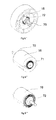
figure 8 est une perspective schématique illustrant un procédé de mesure du bruit émis par un sèche-cheveux.
- The
figure 1 is a schematic longitudinal section of a hair dryer according to the invention. - The
figure 2 is a schematic overall perspective of the motorcycle fan group of the hair dryer shown in thefigure 1 . - The
figure 3 is a schematic perspective of the fan motorcycle fan assembly shown in thefigure 2 . - The
figure 4 is an axial section of the fan shown in thefigure 3 . - The
figure 5 is a diagrammatic perspective view of a sound-absorbing rib intended to be placed in the suction duct of the hair dryer illustrated in FIG.figure 1 . - The
figure 6 is a schematic perspective showing the electric motor, the motorcycle fan assembly shown in thefigure 2 , associated with two suspension cradles. - The
Figures 6 ', 6 "and 6"' are schematic perspective views showing the electric motor, of the motorcycle fan assembly shown atfigure 2 , associated with two fixing rings, - The
figure 7 is a schematic perspective showing a suspension cradle of the electric motor of the motorcycle fan unit. - The
figure 8 is a schematic perspective illustrating a method of measuring noise emitted by a hair dryer.
Un sèche-cheveux, selon l'invention, tel qu'illustré à la
Le corps tubulaire 2 comprend, à l'avant, une extrémité ouverte 4 de sortie de l'air. La sortie 4 possède une forme sensiblement circulaire étant entendu que la sortie d'air 4 pourrait également présenter une forme d'ellipse ou oblongue. Le corps tubulaire 2 comprend en outre à proximité d'une extrémité arrière 5, opposée à la sortie 4, une entrée d'air périphérique 6 qui s'étend sur une partie du ou sur tout le pourtour du corps 2.The tubular body 2 comprises, at the front, an
Afin d'assurer un soufflage d'air par la sortie 4, le sèche-cheveux 1 comprend un groupe moto ventilateur 10 disposé dans le corps tubulaire 2 entre l'entrée 6 et la sortie 4. Le groupe moto ventilateur 10 comprend un rotor 11 qui est situé dans une chambre de travail 12 raccordée, d'une part, à l'entrée d'air 6 par un conduit d'aspiration 13 et, d'autre part, à la sortie de l'air 4 par un conduit de soufflage 14. Le rotor 11 est solidaire d'un arbre d'entraînement 15 d'un moteur électrique 16 disposé à l'intérieur du conduit de soufflage 14.In order to ensure air blowing through the
Conformément à une caractéristique essentielle de l'invention, le rotor 11 forme un ventilateur centrifuge adapté pour aspirer l'air du conduit 13 dans la chambre de travail 12 parallèlement à l'axe longitudinal Δ et le refouler radialement pour rejoindre le conduit de soufflage 14 après avoir été dévié à 90° par la paroi périphérique externe 17 de la chambre de travail 12.According to an essential characteristic of the invention, the
Selon l'exemple illustré, le rotor 11 comprend, comme le montrent les
Afin d'augmenter les performances aérodynamiques du rotor 11, il est également mis en oeuvre un plafond annulaire 25 qui est solidaire des aubes 21 et qui définit en son centre une bouche circulaire d'aspiration 26. Pour que le plafond annulaire 25 n'ait pas une influence négative sur les performances du rotor, le diamètre interne Da de la bouche d'aspiration 26 est choisi pour être au moins égal à 0,6 fois le diamètre externe De du rotor 11.In order to increase the aerodynamic performance of the
Afin d'être intégrable dans un corps de sèche-cheveux de dimensions raisonnables, le rotor pourra être choisi de manière à avoir un diamètre externe De inférieur à 70 mm et, par exemple, de l'ordre de 65 mm.In order to be integrable in a hair dryer body of reasonable dimensions, the rotor may be chosen so as to have an outer diameter of less than 70 mm and, for example, of the order of 65 mm.
Toujours dans le sens d'une optimisation aérodynamique du rotor et dans le cas où celui-ci est destiné à fonctionner à des vitesses de rotation comprises entre 7000 et 12 000 tr/min, les aubes 21 seront dimensionnées pour présenter une hauteur axiale h, mesurée parallèlement à l'axe Δ, comprise entre 0,30 et 0,5 fois le diamètre externe De du rotor. Dans le cas d'un rotor dont le diamètre externe est de l'ordre de 65 mm, les aubes 21 seront réalisées de manière à posséder une hauteur h comprise entre 20 mm et 30 mm, préférentiellement entre 22 et 30mm. Afin de limiter les bruits aériens et les vibrations, la vitesse de rotation d'un tel rotor 11 sera, de préférence, choisie pour être inférieure ou égale à 10 000 tr/min.Still in the sense of an aerodynamic optimization of the rotor and in the case where it is intended to operate at rotational speeds of between 7000 and 12 000 rpm, the
Afin de limiter la propagation directe des bruits hors du conduit d'aspiration 13, ce dernier sera réalisé de manière à présenter une longueur axiale l supérieure ou égale au diamètre interne Da de la bouche d'aspiration 26. On entend par « longueur axiale l » illustrée en
Afin d'optimiser plus encore l'atténuation des bruits, le conduit d'aspiration 13 comprend un noyau central 30 qui lui confère une forme annulaire depuis l'entrée d'air 6 jusqu'à, sensiblement, la chambre de travail 12. La surface du noyau 30 délimitant le conduit d'aspiration 13 présente selon l'exemple illustré une forme à symétrie de révolution d'axe Δ avec une génératrice concave de sorte que le diamètre extérieur du noyau central 30 décroît vers la chambre de travail 12. Afin d'assurer une continuité aéraulique avec le noyau 30, le plateau d'entraînement 20 comprend un plot central 31 qui présente un diamètre sensiblement égal au diamètre de la partie adjacente du noyau 30. L'effet absorbeur de bruit du noyau 30 peut encore être renforcé en réalisant le noyau en partie au moins en un matériau alvéolaire tel que de la mousse de polyuréthane à base de polyester.In order to further optimize the attenuation of the noises, the
Le noyau 30 pourra alors être formé par une coque rigide remplie en partie au moins dudit matériau alvéolaire. Le noyau peut aussi être réalisé sous la forme d'une pièce moulée en ce matériau alvéolaire.The core 30 may then be formed by a rigid shell filled at least partially with said cellular material. The core may also be in the form of a molded piece of this cellular material.
Selon l'exemple illustré, la propagation vers l'extérieur des bruits du conduit d'aspiration 13 est également limitée par la présence d'au moins un circuit de précanalisation pour faciliter la pénétration de l'air dans les aubes (dépendant du sens de rotation du rotor). Ce circuit de précanalisation de l'air (32, 33) est formé par au moins une nervure antibruit 32 sensiblement perpendiculaire à la paroi externe 33 du conduit d'aspiration 13. Selon l'exemple illustré, la nervure antibruit 32 est constituée par une pièce rapportée de forme hélicoïdale comme le montre la
De manière à limiter la propagation des bruits et vibrations du moteur 16 en fonctionnement, le sèche-cheveux 1 comprend un carter tubulaire 40 à l'intérieur duquel le moteur 16 est confiné. Le carter tubulaire 40 présente une forme cylindrique de révolution d'axe Δ. Le carter tubulaire 40 est centré à l'intérieur du conduit de soufflage 14 par une ceinture coaxiale 41 en appui contre la paroi interne du conduit de soufflage 14. La ceinture 41 et le carter tubulaire 40 sont liés l'un à l'autre par des ailettes radiales 42 qui aménagent un espace de passage pour l'air entre le carter 40 et la ceinture 41 et qui canalisent l'air en provenance de la chambre de travail 12 pour s'opposer à son éventuel mouvement tourbillonnaire.In order to limit the propagation of the noise and vibrations of the
Le confinement du moteur 16 dans le carter tubulaire 40 est assuré au moyen de deux disques 45, visibles
Selon l'exemple illustré et comme le montre plus particulièrement la
Afin de limiter la propagation des vibrations du moteur 16 au reste du corps tubulaire 2, le moteur 16 est maintenu dans le carter 40 par au moins un et, selon l'exemple illustré, deux berceaux de suspension 50, mieux visibles à la
Alternativement, comme illustré en
Le sèche-cheveux 1 comprend en outre en aval du groupe moto ventilateur 10 des moyens 55 de chauffage électrique de l'air soufflé. Les moyens de chauffage 55 peuvent être réalisés de toute façon appropriée et par exemple sous la forme d'une résistance électrique chauffante maintenue par des ailettes radiales réalisées en matériaux isolants tels que par exemple des feuilles de mica.The hair dryer 1 further comprises downstream of the
Afin de contribuer à l'amortissement du bruit de fonctionnement du sèche-cheveux 1, certaines parties au moins de la surface externe du corps pourront également être réalisées en matériau alvéolaire tel que une mousse de polyuréthane à base de polyester.In order to contribute to the damping of the operating noise of the hair dryer 1, at least some parts of the external surface of the body may also be made of cellular material such as a polyurethane foam based on polyester.
Le sèche-cheveux 1, selon l'invention, ainsi constitué fonctionne, à performance de chauffage et de débit d'air équivalente, en émettant moins de bruit que les sèche-cheveux selon l'antérieur.The hair dryer 1, according to the invention, thus constituted operates with heating performance and equivalent air flow, emitting less noise than hair dryers according to the previous.
Afin de bénéficier d'une base de comparaison objective rendant compte des performances sonores d'un sèche-cheveux tant en ce qui concerne la personne tenant le sèche-cheveux que la personne dont les cheveux sont séchés ou encore en ce qui concerne l'utilisateur se séchant seul les cheveux, l'invention propose un procédé de mesure permettant de quantifier objectivement la pression acoustique subie par l'environnement.In order to benefit from an objective basis of comparison that accounts for the sound performance of a hair dryer both with regard to the person holding the hair dryer and the person whose hair is dried or with regard to the user drying the hair alone, the invention provides a measurement method for objectively quantifying the acoustic pressure experienced by the environment.
Afin de quantifier le bruit reçu par la personne dont les cheveux sont séchés au moyen du sèche-cheveux, il est proposé de mettre en oeuvre une tête humaine factice T comme illustrée à la
Pour réaliser une première mesure dB1 le sèche-cheveux 1 en fonctionnement est placé dans une première position P1 d'un côté arrière, par exemple droit, de la tête T avec l'axe longitudinal Δ contenu dans le plan horizontal H passant par les micros 60 et faisant avec un plan sagittal S, de symétrie de la tête T, un angle α compris entre 30° et 50° et, par exemple, égal à 45°.To perform a first measurement dB1 the hair dryer 1 in operation is placed in a first position P1 of a rear side, for example right, of the head T with the longitudinal axis Δ contained in the horizontal plane H passing through the
Pour réaliser une deuxième mesure dB2, le sèche-cheveux 1 en fonctionnement est relevé jusqu'à une deuxième position P2 de manière que sa sortie soit dirigée vers le bas en direction de la tête T. Dans cette deuxième position P2, l'axe longitudinal Δ est situé dans un plan incliné P faisant un angle β avec le plan horizontal H qu'il coupe au niveau de la droite passant par les micros 60. L'angle β possède une valeur comprise entre 30° et 50° et par exemple égal à 45°. Dans la deuxième position P2, l'axe longitudinal Δ forme le même angle α que dans la position P1 avec le plan sagittal S.To perform a second measurement dB2, the hair dryer 1 in operation is raised to a second position P2 so that its output is directed downwards towards the head T. In this second position P2, the longitudinal axis Δ is located in an inclined plane P making an angle β with the horizontal plane H that it intersects at the line passing through the
Il est également réalisé une troisième mesure dB3 dans une troisième position P3 symétrique de la première position P1 par rapport au plan sagittal S. Il est enfin réalisé une quatrième mesure dB4 dans une quatrième position P4 symétrique de la deuxième position P2 par rapport au plan sagittal S. Il peut être remarqué que dans les positions P1 et P2, l'axe longitudinal Δ est compris dans un même plan vertical V tandis que dans les positions P3 et P4 l'axe longitudinal Δ est compris dans un même plan vertical V' symétrique du plan vertical V par rapport au plan sagittal S.It is also realized a third measurement dB3 in a third position P3 symmetrical with the first position P1 with respect to the sagittal plane S. Finally, a fourth measurement dB4 is made in a fourth position P4 symmetrical with the second position P2 with respect to the sagittal plane S. It can be noticed that in the positions P1 and P2, the longitudinal axis Δ is included in the same vertical plane V while in the positions P3 and P4 the longitudinal axis Δ is included in the same vertical plane V 'symmetrical of the vertical plane V with respect to the sagittal plane S.
Il doit être noté que dans chacune des positions de mesure P1 à P4, la sortie 4 est placée à une distance D, mesurée le long de l'axe Δ, de la surface externe de la tête T comprise entre 5 cm et 20 cm et par exemple égale à 10 cm.It should be noted that in each of the measuring positions P1 to P4, the
Chaque valeur dB1 à dB4 correspond à la somme des mesures de pression acoustique des deux micros 60 pour chaque position correspondante.Each value dB1 to dB4 corresponds to the sum of the sound pressure measurements of the two
Afin de donner une note synthétique il peut être réalisé une moyenne MdB des mesures dB1 à dB2 ou des mesures dB1 à dB4.In order to give a synthetic score, it is possible to realize a mean dB of the measurements dB1 to dB2 or measurements dB1 to dB4.
Ainsi dans le cas d'un sèche-cheveux selon l'invention présentant un débit d'environ 68m3/h-avec une puissance de chauffage d'environ 1800W la moyenne MdB a une valeur d'environ 69dB tandis que pour un sèche-cheveux selon l'art antérieur présentant le même débit et la même puissance de chauffage la moyenne MdB a une valeur d'environ 75dB.Thus in the case of a hair dryer according to the invention having a flow rate of about 68 m 3 / h-with a heating power of about 1800W the average MdB has a value of about 69 dB while for a hair dryer according to the prior art having the same flow rate and the same heating power the average MdB has a value of about 75 dB.
L'évaluation du bruit engendré par le sèche-cheveux en fonctionnement peut être complétée en mesurant la pression acoustique dB5 en un point situé sur l'axe longitudinal Δ à l'arrière du sèche-cheveux à une distance D' comprise entre 15cm et 30 cm et par exemple égale à 20 cm. Cette mesure dB5 rend compte du bruit subi par un utilisateur du sèche-cheveux 1 qui sèche les cheveux d'une autre personne.The evaluation of the noise generated by the hair dryer in operation can be completed by measuring the sound pressure dB5 at a point on the longitudinal axis Δ at the back of the hair dryer at a distance D between 15 cm and 30 cm. cm and for example equal to 20 cm. This dB5 measurement makes account of the noise experienced by a user of the hair dryer 1 which dries the hair of another person.
Selon l'exemple décrit précédemment et illustré aux figures, les éléments constitutifs du corps tubulaire tels que par exemple l'enveloppe extérieure du corps, le carter 40, le noyau 30 sont des éléments indépendants. Toutefois, ces différents éléments pourraient faire partie intégrante des deux coques qui constituent l'enveloppe. De même selon l'exemple illustré le canal de soufflage se resserre au niveau de la sortie 4. Bien entendu une telle configuration n'est pas nécessaire à la réalisation d'un sèche-cheveux selon l'invention et le canal de soufflage 14 pourrait présenter une section constante sur toute sa longueur.According to the example described above and illustrated in the figures, the constituent elements of the tubular body such as for example the outer casing of the body, the
Bien entendu diverses autres modifications peuvent être apportées au sèche-cheveux selon l'invention dans le cadre des revendications annexées.Of course various other modifications can be made to the hair dryer according to the invention within the scope of the appended claims.
Claims (4)
- A method for evaluating the noise produced by a longitudinal axis (Δ) hair dryer with an outlet towards the front. The method comprises the following steps:- implementation of a dummy human head (T) with two microphones (60), one placed at the left ear and the other at the right ear of the dummy head on each side of the sagittal plane of symmetry (S) of the head,- placement of the hair dryer in operation at one side of the rear of the head with the outlet directed towards the head (T) and situated at a distance (D) of between 5 cm and 20 cm from the head, with the longitudinal axis (Δ) of the hair dryer being in a vertical plane (V) forming an angle α of between 30° and 50° with the sagittal plane of symmetry (S) with the head (T), and:- positioning the longitudinal axis (Δ) of the hair dryer in a horizontal plane (H) passing through the microphones, and then measuring the left and right sound pressure with the microphones and calculating the average dB1 of these two measurements,- positioning the longitudinal axis (Δ) of the hair dryer with the outlet facing downward in an inclined plane (P) forming an angle (β) of between 30° and 50° with the horizontal plane, and then measuring the left and right sound pressure with the microphones and calculating the average dB2 of these two measurements.
- Evaluation method according to claim 1, characterised in that it comprises the following additional steps:- placement of the hair dryer in operation at the other side of the rear of the head with the outlet directed towards the head and situated at a distance (D) from the head, with the longitudinal axis (Δ) of the hair dryer in a vertical plane (V') of the symmetrical plane (V) relative to the sagittal plane of symmetry (S) of the head (T):- positioning the longitudinal axis of the hair dryer in the horizontal plane (H), and then measuring the left and right sound pressure with the microphones (60) and calculating the average dB3 of these two measurements,- positioning the longitudinal axis of the hair dryer with the outlet facing downward in an inclined plane (P), and then measuring the left and right sound pressure with the microphones and calculating the average dB4 of these two measurements.
- Evaluation method according to claim 1 or 2, characterised in that it comprises a step for calculating the average of values dB1 and dB2, or the average of dB1, dB2, dB3 and dB4.
- Evaluation method according to any one of claims 1 to 3, characterised in that it comprises a step for measuring sound pressure dB5 at a point on the longitudinal axis (Δ) to the rear of the hair dryer at a distance (D') of between 15 cm and 30 cm.
Applications Claiming Priority (2)
| Application Number | Priority Date | Filing Date | Title |
|---|---|---|---|
| FR1059345A FR2967490B1 (en) | 2010-11-15 | 2010-11-15 | METHOD FOR MEASURING THE NOISE OF A HAIR DRYER |
| PCT/FR2011/052634 WO2012066224A1 (en) | 2010-11-15 | 2011-11-14 | Method of measuring the noise of a hairdryer |
Publications (2)
| Publication Number | Publication Date |
|---|---|
| EP2641067A1 EP2641067A1 (en) | 2013-09-25 |
| EP2641067B1 true EP2641067B1 (en) | 2016-01-13 |
Family
ID=44212155
Family Applications (1)
| Application Number | Title | Priority Date | Filing Date |
|---|---|---|---|
| EP11794814.1A Active EP2641067B1 (en) | 2010-11-15 | 2011-11-14 | Method of measuring the noise of a hairdryer |
Country Status (5)
| Country | Link |
|---|---|
| EP (1) | EP2641067B1 (en) |
| CN (1) | CN103210288B (en) |
| ES (1) | ES2565217T3 (en) |
| FR (1) | FR2967490B1 (en) |
| WO (1) | WO2012066224A1 (en) |
Families Citing this family (1)
| Publication number | Priority date | Publication date | Assignee | Title |
|---|---|---|---|---|
| CN104075796A (en) * | 2013-12-17 | 2014-10-01 | 国家电网公司 | High-accuracy individual noise measurement method |
Family Cites Families (6)
| Publication number | Priority date | Publication date | Assignee | Title |
|---|---|---|---|---|
| JPH11142231A (en) * | 1997-11-10 | 1999-05-28 | Toyota Central Res & Dev Lab Inc | Noise analyzer |
| WO2004084176A1 (en) * | 2000-08-15 | 2004-09-30 | Yoichi Ando | Sound evaluating method and its system |
| US6766590B2 (en) * | 2002-07-15 | 2004-07-27 | Wahl Clipper Corporation | Hand held drying device |
| EP1692962A1 (en) * | 2005-02-18 | 2006-08-23 | Faco S.A. | Hair dryer with improved acoustic confort |
| FR2926704B1 (en) * | 2008-01-25 | 2013-02-01 | Velecta Paramount | SILENCER FOR DRYING APPARATUS AND SILENT HAIR DRYER |
| US20100064542A1 (en) * | 2008-09-15 | 2010-03-18 | Hamilton Beach Brands, Inc. | Hair drying apparatus |
-
2010
- 2010-11-15 FR FR1059345A patent/FR2967490B1/en not_active Expired - Fee Related
-
2011
- 2011-11-14 ES ES11794814.1T patent/ES2565217T3/en active Active
- 2011-11-14 WO PCT/FR2011/052634 patent/WO2012066224A1/en active Application Filing
- 2011-11-14 CN CN201180054872.0A patent/CN103210288B/en not_active Expired - Fee Related
- 2011-11-14 EP EP11794814.1A patent/EP2641067B1/en active Active
Also Published As
| Publication number | Publication date |
|---|---|
| WO2012066224A1 (en) | 2012-05-24 |
| ES2565217T3 (en) | 2016-04-01 |
| FR2967490A1 (en) | 2012-05-18 |
| CN103210288B (en) | 2014-10-15 |
| FR2967490B1 (en) | 2012-12-21 |
| EP2641067A1 (en) | 2013-09-25 |
| CN103210288A (en) | 2013-07-17 |
Similar Documents
| Publication | Publication Date | Title |
|---|---|---|
| EP2452585B1 (en) | Hair dryer having a particular air duct | |
| EP2237700B1 (en) | Silencer for drying appliance and quiet hairdryer | |
| EP3097816B1 (en) | Accessory for blowing hairstyling device and device provided with same | |
| EP2512282B1 (en) | Hairdryer having a passive silencer system | |
| EP2452584B1 (en) | Hair dryer with a centrifugal fan | |
| EP2151584A1 (en) | Centrifugal fan | |
| WO2019092358A1 (en) | Method for moving air | |
| EP2779863B1 (en) | Hairdryer with concentric blades | |
| WO2013072625A1 (en) | Hairdryer with special gripping means | |
| EP2641067B1 (en) | Method of measuring the noise of a hairdryer | |
| WO2023118683A1 (en) | Hair-styling appliance comprising an improved blower module with counter-rotating fans, and an interposed porous medium | |
| EP3367840B1 (en) | Hairdryer with improved acoustic performance | |
| EP1119270A1 (en) | Hair dryer | |
| WO2023118682A1 (en) | Hair-styling appliance comprising an improved blower module with counter-rotating fans | |
| EP3925482A1 (en) | Hairdryer with shock absorber support | |
| EP3926173A1 (en) | Propeller for blowing device comprising radial channels for air flow | |
| EP2779862B1 (en) | Method for measuring the efficiency of a hairdryer | |
| EP3903626A1 (en) | Hair-styling appliance with improved blowing module |
Legal Events
| Date | Code | Title | Description |
|---|---|---|---|
| PUAI | Public reference made under article 153(3) epc to a published international application that has entered the european phase |
Free format text: ORIGINAL CODE: 0009012 |
|
| 17P | Request for examination filed |
Effective date: 20130405 |
|
| AK | Designated contracting states |
Kind code of ref document: A1 Designated state(s): AL AT BE BG CH CY CZ DE DK EE ES FI FR GB GR HR HU IE IS IT LI LT LU LV MC MK MT NL NO PL PT RO RS SE SI SK SM TR |
|
| DAX | Request for extension of the european patent (deleted) | ||
| GRAP | Despatch of communication of intention to grant a patent |
Free format text: ORIGINAL CODE: EPIDOSNIGR1 |
|
| GRAJ | Information related to disapproval of communication of intention to grant by the applicant or resumption of examination proceedings by the epo deleted |
Free format text: ORIGINAL CODE: EPIDOSDIGR1 |
|
| INTG | Intention to grant announced |
Effective date: 20150605 |
|
| GRAP | Despatch of communication of intention to grant a patent |
Free format text: ORIGINAL CODE: EPIDOSNIGR1 |
|
| GRAJ | Information related to disapproval of communication of intention to grant by the applicant or resumption of examination proceedings by the epo deleted |
Free format text: ORIGINAL CODE: EPIDOSDIGR1 |
|
| GRAP | Despatch of communication of intention to grant a patent |
Free format text: ORIGINAL CODE: EPIDOSNIGR1 |
|
| INTG | Intention to grant announced |
Effective date: 20150702 |
|
| INTG | Intention to grant announced |
Effective date: 20150715 |
|
| GRAS | Grant fee paid |
Free format text: ORIGINAL CODE: EPIDOSNIGR3 |
|
| GRAA | (expected) grant |
Free format text: ORIGINAL CODE: 0009210 |
|
| AK | Designated contracting states |
Kind code of ref document: B1 Designated state(s): AL AT BE BG CH CY CZ DE DK EE ES FI FR GB GR HR HU IE IS IT LI LT LU LV MC MK MT NL NO PL PT RO RS SE SI SK SM TR |
|
| REG | Reference to a national code |
Ref country code: GB Ref legal event code: FG4D Free format text: NOT ENGLISH |
|
| REG | Reference to a national code |
Ref country code: CH Ref legal event code: EP |
|
| REG | Reference to a national code |
Ref country code: IE Ref legal event code: FG4D Free format text: LANGUAGE OF EP DOCUMENT: FRENCH |
|
| REG | Reference to a national code |
Ref country code: AT Ref legal event code: REF Ref document number: 770845 Country of ref document: AT Kind code of ref document: T Effective date: 20160215 |
|
| REG | Reference to a national code |
Ref country code: DE Ref legal event code: R096 Ref document number: 602011022695 Country of ref document: DE |
|
| REG | Reference to a national code |
Ref country code: ES Ref legal event code: FG2A Ref document number: 2565217 Country of ref document: ES Kind code of ref document: T3 Effective date: 20160401 |
|
| REG | Reference to a national code |
Ref country code: LT Ref legal event code: MG4D |
|
| REG | Reference to a national code |
Ref country code: NL Ref legal event code: MP Effective date: 20160113 |
|
| REG | Reference to a national code |
Ref country code: AT Ref legal event code: MK05 Ref document number: 770845 Country of ref document: AT Kind code of ref document: T Effective date: 20160113 |
|
| PG25 | Lapsed in a contracting state [announced via postgrant information from national office to epo] |
Ref country code: NL Free format text: LAPSE BECAUSE OF FAILURE TO SUBMIT A TRANSLATION OF THE DESCRIPTION OR TO PAY THE FEE WITHIN THE PRESCRIBED TIME-LIMIT Effective date: 20160113 |
|
| PG25 | Lapsed in a contracting state [announced via postgrant information from national office to epo] |
Ref country code: HR Free format text: LAPSE BECAUSE OF FAILURE TO SUBMIT A TRANSLATION OF THE DESCRIPTION OR TO PAY THE FEE WITHIN THE PRESCRIBED TIME-LIMIT Effective date: 20160113 Ref country code: GR Free format text: LAPSE BECAUSE OF FAILURE TO SUBMIT A TRANSLATION OF THE DESCRIPTION OR TO PAY THE FEE WITHIN THE PRESCRIBED TIME-LIMIT Effective date: 20160414 Ref country code: NO Free format text: LAPSE BECAUSE OF FAILURE TO SUBMIT A TRANSLATION OF THE DESCRIPTION OR TO PAY THE FEE WITHIN THE PRESCRIBED TIME-LIMIT Effective date: 20160413 Ref country code: FI Free format text: LAPSE BECAUSE OF FAILURE TO SUBMIT A TRANSLATION OF THE DESCRIPTION OR TO PAY THE FEE WITHIN THE PRESCRIBED TIME-LIMIT Effective date: 20160113 |
|
| PG25 | Lapsed in a contracting state [announced via postgrant information from national office to epo] |
Ref country code: AT Free format text: LAPSE BECAUSE OF FAILURE TO SUBMIT A TRANSLATION OF THE DESCRIPTION OR TO PAY THE FEE WITHIN THE PRESCRIBED TIME-LIMIT Effective date: 20160113 Ref country code: RS Free format text: LAPSE BECAUSE OF FAILURE TO SUBMIT A TRANSLATION OF THE DESCRIPTION OR TO PAY THE FEE WITHIN THE PRESCRIBED TIME-LIMIT Effective date: 20160113 Ref country code: IS Free format text: LAPSE BECAUSE OF FAILURE TO SUBMIT A TRANSLATION OF THE DESCRIPTION OR TO PAY THE FEE WITHIN THE PRESCRIBED TIME-LIMIT Effective date: 20160513 Ref country code: PT Free format text: LAPSE BECAUSE OF FAILURE TO SUBMIT A TRANSLATION OF THE DESCRIPTION OR TO PAY THE FEE WITHIN THE PRESCRIBED TIME-LIMIT Effective date: 20160513 Ref country code: PL Free format text: LAPSE BECAUSE OF FAILURE TO SUBMIT A TRANSLATION OF THE DESCRIPTION OR TO PAY THE FEE WITHIN THE PRESCRIBED TIME-LIMIT Effective date: 20160113 Ref country code: LT Free format text: LAPSE BECAUSE OF FAILURE TO SUBMIT A TRANSLATION OF THE DESCRIPTION OR TO PAY THE FEE WITHIN THE PRESCRIBED TIME-LIMIT Effective date: 20160113 Ref country code: LV Free format text: LAPSE BECAUSE OF FAILURE TO SUBMIT A TRANSLATION OF THE DESCRIPTION OR TO PAY THE FEE WITHIN THE PRESCRIBED TIME-LIMIT Effective date: 20160113 Ref country code: SE Free format text: LAPSE BECAUSE OF FAILURE TO SUBMIT A TRANSLATION OF THE DESCRIPTION OR TO PAY THE FEE WITHIN THE PRESCRIBED TIME-LIMIT Effective date: 20160113 |
|
| RAP2 | Party data changed (patent owner data changed or rights of a patent transferred) |
Owner name: SEB S.A. |
|
| REG | Reference to a national code |
Ref country code: CH Ref legal event code: PCOW Free format text: NEW ADDRESS: 112 CHEMIN DU MOULIN CARRON CAMPUS SEB, 69130 ECULLY (FR) Ref country code: DE Ref legal event code: R097 Ref document number: 602011022695 Country of ref document: DE |
|
| PG25 | Lapsed in a contracting state [announced via postgrant information from national office to epo] |
Ref country code: DK Free format text: LAPSE BECAUSE OF FAILURE TO SUBMIT A TRANSLATION OF THE DESCRIPTION OR TO PAY THE FEE WITHIN THE PRESCRIBED TIME-LIMIT Effective date: 20160113 Ref country code: EE Free format text: LAPSE BECAUSE OF FAILURE TO SUBMIT A TRANSLATION OF THE DESCRIPTION OR TO PAY THE FEE WITHIN THE PRESCRIBED TIME-LIMIT Effective date: 20160113 |
|
| PLBE | No opposition filed within time limit |
Free format text: ORIGINAL CODE: 0009261 |
|
| STAA | Information on the status of an ep patent application or granted ep patent |
Free format text: STATUS: NO OPPOSITION FILED WITHIN TIME LIMIT |
|
| PG25 | Lapsed in a contracting state [announced via postgrant information from national office to epo] |
Ref country code: SK Free format text: LAPSE BECAUSE OF FAILURE TO SUBMIT A TRANSLATION OF THE DESCRIPTION OR TO PAY THE FEE WITHIN THE PRESCRIBED TIME-LIMIT Effective date: 20160113 Ref country code: CZ Free format text: LAPSE BECAUSE OF FAILURE TO SUBMIT A TRANSLATION OF THE DESCRIPTION OR TO PAY THE FEE WITHIN THE PRESCRIBED TIME-LIMIT Effective date: 20160113 Ref country code: RO Free format text: LAPSE BECAUSE OF FAILURE TO SUBMIT A TRANSLATION OF THE DESCRIPTION OR TO PAY THE FEE WITHIN THE PRESCRIBED TIME-LIMIT Effective date: 20160113 Ref country code: SM Free format text: LAPSE BECAUSE OF FAILURE TO SUBMIT A TRANSLATION OF THE DESCRIPTION OR TO PAY THE FEE WITHIN THE PRESCRIBED TIME-LIMIT Effective date: 20160113 |
|
| REG | Reference to a national code |
Ref country code: FR Ref legal event code: PLFP Year of fee payment: 6 |
|
| 26N | No opposition filed |
Effective date: 20161014 |
|
| PGFP | Annual fee paid to national office [announced via postgrant information from national office to epo] |
Ref country code: MC Payment date: 20161020 Year of fee payment: 6 Ref country code: GB Payment date: 20161121 Year of fee payment: 6 Ref country code: LU Payment date: 20161128 Year of fee payment: 6 Ref country code: DE Payment date: 20161115 Year of fee payment: 6 Ref country code: CH Payment date: 20161121 Year of fee payment: 6 |
|
| PG25 | Lapsed in a contracting state [announced via postgrant information from national office to epo] |
Ref country code: SI Free format text: LAPSE BECAUSE OF FAILURE TO SUBMIT A TRANSLATION OF THE DESCRIPTION OR TO PAY THE FEE WITHIN THE PRESCRIBED TIME-LIMIT Effective date: 20160113 Ref country code: BG Free format text: LAPSE BECAUSE OF FAILURE TO SUBMIT A TRANSLATION OF THE DESCRIPTION OR TO PAY THE FEE WITHIN THE PRESCRIBED TIME-LIMIT Effective date: 20160413 |
|
| PGFP | Annual fee paid to national office [announced via postgrant information from national office to epo] |
Ref country code: ES Payment date: 20161130 Year of fee payment: 6 Ref country code: BE Payment date: 20161125 Year of fee payment: 6 Ref country code: IT Payment date: 20161117 Year of fee payment: 6 |
|
| REG | Reference to a national code |
Ref country code: FR Ref legal event code: CA Effective date: 20170518 |
|
| REG | Reference to a national code |
Ref country code: IE Ref legal event code: MM4A |
|
| PG25 | Lapsed in a contracting state [announced via postgrant information from national office to epo] |
Ref country code: IE Free format text: LAPSE BECAUSE OF NON-PAYMENT OF DUE FEES Effective date: 20161114 |
|
| REG | Reference to a national code |
Ref country code: FR Ref legal event code: PLFP Year of fee payment: 7 |
|
| PG25 | Lapsed in a contracting state [announced via postgrant information from national office to epo] |
Ref country code: CY Free format text: LAPSE BECAUSE OF FAILURE TO SUBMIT A TRANSLATION OF THE DESCRIPTION OR TO PAY THE FEE WITHIN THE PRESCRIBED TIME-LIMIT Effective date: 20160113 Ref country code: HU Free format text: LAPSE BECAUSE OF FAILURE TO SUBMIT A TRANSLATION OF THE DESCRIPTION OR TO PAY THE FEE WITHIN THE PRESCRIBED TIME-LIMIT; INVALID AB INITIO Effective date: 20111114 |
|
| REG | Reference to a national code |
Ref country code: DE Ref legal event code: R119 Ref document number: 602011022695 Country of ref document: DE |
|
| PG25 | Lapsed in a contracting state [announced via postgrant information from national office to epo] |
Ref country code: MK Free format text: LAPSE BECAUSE OF FAILURE TO SUBMIT A TRANSLATION OF THE DESCRIPTION OR TO PAY THE FEE WITHIN THE PRESCRIBED TIME-LIMIT Effective date: 20160113 Ref country code: MC Free format text: LAPSE BECAUSE OF NON-PAYMENT OF DUE FEES Effective date: 20171130 |
|
| GBPC | Gb: european patent ceased through non-payment of renewal fee |
Effective date: 20171114 |
|
| PG25 | Lapsed in a contracting state [announced via postgrant information from national office to epo] |
Ref country code: CH Free format text: LAPSE BECAUSE OF NON-PAYMENT OF DUE FEES Effective date: 20171130 Ref country code: LI Free format text: LAPSE BECAUSE OF NON-PAYMENT OF DUE FEES Effective date: 20171130 |
|
| PG25 | Lapsed in a contracting state [announced via postgrant information from national office to epo] |
Ref country code: LU Free format text: LAPSE BECAUSE OF NON-PAYMENT OF DUE FEES Effective date: 20171114 |
|
| REG | Reference to a national code |
Ref country code: BE Ref legal event code: MM Effective date: 20171130 Ref country code: BE Ref legal event code: PD Owner name: SEB S.A.; FR Free format text: DETAILS ASSIGNMENT: CHANGE OF OWNER(S), AUTRE, ADRESSE Effective date: 20161107 |
|
| PG25 | Lapsed in a contracting state [announced via postgrant information from national office to epo] |
Ref country code: MT Free format text: LAPSE BECAUSE OF FAILURE TO SUBMIT A TRANSLATION OF THE DESCRIPTION OR TO PAY THE FEE WITHIN THE PRESCRIBED TIME-LIMIT Effective date: 20160113 |
|
| PG25 | Lapsed in a contracting state [announced via postgrant information from national office to epo] |
Ref country code: IT Free format text: LAPSE BECAUSE OF NON-PAYMENT OF DUE FEES Effective date: 20171114 Ref country code: DE Free format text: LAPSE BECAUSE OF NON-PAYMENT OF DUE FEES Effective date: 20180602 Ref country code: TR Free format text: LAPSE BECAUSE OF FAILURE TO SUBMIT A TRANSLATION OF THE DESCRIPTION OR TO PAY THE FEE WITHIN THE PRESCRIBED TIME-LIMIT Effective date: 20160113 Ref country code: AL Free format text: LAPSE BECAUSE OF FAILURE TO SUBMIT A TRANSLATION OF THE DESCRIPTION OR TO PAY THE FEE WITHIN THE PRESCRIBED TIME-LIMIT Effective date: 20160113 |
|
| PG25 | Lapsed in a contracting state [announced via postgrant information from national office to epo] |
Ref country code: GB Free format text: LAPSE BECAUSE OF NON-PAYMENT OF DUE FEES Effective date: 20171114 Ref country code: BE Free format text: LAPSE BECAUSE OF NON-PAYMENT OF DUE FEES Effective date: 20171130 |
|
| REG | Reference to a national code |
Ref country code: ES Ref legal event code: FD2A Effective date: 20181226 |
|
| PG25 | Lapsed in a contracting state [announced via postgrant information from national office to epo] |
Ref country code: ES Free format text: LAPSE BECAUSE OF NON-PAYMENT OF DUE FEES Effective date: 20171115 |
|
| PGFP | Annual fee paid to national office [announced via postgrant information from national office to epo] |
Ref country code: FR Payment date: 20231124 Year of fee payment: 13 |