EP2640273B1 - Filtriervorrichtung zum filtern eines ultraschallsignals - Google Patents
Filtriervorrichtung zum filtern eines ultraschallsignals Download PDFInfo
- Publication number
- EP2640273B1 EP2640273B1 EP11799134.9A EP11799134A EP2640273B1 EP 2640273 B1 EP2640273 B1 EP 2640273B1 EP 11799134 A EP11799134 A EP 11799134A EP 2640273 B1 EP2640273 B1 EP 2640273B1
- Authority
- EP
- European Patent Office
- Prior art keywords
- ultrasound
- signal
- unit
- filtering
- ultrasound signal
- Prior art date
- Legal status (The legal status is an assumption and is not a legal conclusion. Google has not performed a legal analysis and makes no representation as to the accuracy of the status listed.)
- Active
Links
- 238000002604 ultrasonography Methods 0.000 title claims description 253
- 238000001914 filtration Methods 0.000 title claims description 87
- 238000012937 correction Methods 0.000 claims description 88
- 238000000034 method Methods 0.000 claims description 29
- 238000004590 computer program Methods 0.000 claims description 18
- 230000003321 amplification Effects 0.000 claims description 8
- 238000003199 nucleic acid amplification method Methods 0.000 claims description 8
- 230000036962 time dependent Effects 0.000 claims description 8
- 230000004044 response Effects 0.000 claims description 2
- 238000002679 ablation Methods 0.000 description 41
- 210000001519 tissue Anatomy 0.000 description 13
- 210000005003 heart tissue Anatomy 0.000 description 11
- 230000008878 coupling Effects 0.000 description 7
- 238000010168 coupling process Methods 0.000 description 7
- 238000005859 coupling reaction Methods 0.000 description 7
- 230000003902 lesion Effects 0.000 description 7
- 238000012544 monitoring process Methods 0.000 description 7
- 238000007674 radiofrequency ablation Methods 0.000 description 7
- 238000004364 calculation method Methods 0.000 description 5
- 230000008859 change Effects 0.000 description 5
- 238000003384 imaging method Methods 0.000 description 5
- 238000012545 processing Methods 0.000 description 5
- 238000012800 visualization Methods 0.000 description 5
- 230000001276 controlling effect Effects 0.000 description 4
- 238000003973 irrigation Methods 0.000 description 4
- 230000002262 irrigation Effects 0.000 description 4
- 238000005070 sampling Methods 0.000 description 4
- 230000000875 corresponding effect Effects 0.000 description 3
- 230000000694 effects Effects 0.000 description 3
- 101150000003 subB gene Proteins 0.000 description 3
- 238000012285 ultrasound imaging Methods 0.000 description 3
- 238000010521 absorption reaction Methods 0.000 description 2
- 238000004422 calculation algorithm Methods 0.000 description 2
- 230000001419 dependent effect Effects 0.000 description 2
- 238000002594 fluoroscopy Methods 0.000 description 2
- 230000009467 reduction Effects 0.000 description 2
- FAPWRFPIFSIZLT-UHFFFAOYSA-M Sodium chloride Chemical compound [Na+].[Cl-] FAPWRFPIFSIZLT-UHFFFAOYSA-M 0.000 description 1
- 206010003119 arrhythmia Diseases 0.000 description 1
- 230000008901 benefit Effects 0.000 description 1
- 230000015572 biosynthetic process Effects 0.000 description 1
- 239000008280 blood Substances 0.000 description 1
- 210000004369 blood Anatomy 0.000 description 1
- 238000013153 catheter ablation Methods 0.000 description 1
- 238000006243 chemical reaction Methods 0.000 description 1
- 230000002596 correlated effect Effects 0.000 description 1
- 230000007423 decrease Effects 0.000 description 1
- 238000001514 detection method Methods 0.000 description 1
- 238000002059 diagnostic imaging Methods 0.000 description 1
- 238000002592 echocardiography Methods 0.000 description 1
- 239000012530 fluid Substances 0.000 description 1
- OVBPIULPVIDEAO-LBPRGKRZSA-N folic acid Chemical compound C=1N=C2NC(N)=NC(=O)C2=NC=1CNC1=CC=C(C(=O)N[C@@H](CCC(O)=O)C(O)=O)C=C1 OVBPIULPVIDEAO-LBPRGKRZSA-N 0.000 description 1
- 201000010235 heart cancer Diseases 0.000 description 1
- 208000024348 heart neoplasm Diseases 0.000 description 1
- 210000005246 left atrium Anatomy 0.000 description 1
- 238000002595 magnetic resonance imaging Methods 0.000 description 1
- 238000005259 measurement Methods 0.000 description 1
- 238000012986 modification Methods 0.000 description 1
- 230000004048 modification Effects 0.000 description 1
- 230000003287 optical effect Effects 0.000 description 1
- 210000000056 organ Anatomy 0.000 description 1
- 239000011780 sodium chloride Substances 0.000 description 1
- 238000012795 verification Methods 0.000 description 1
Images


Classifications
-
- A—HUMAN NECESSITIES
- A61—MEDICAL OR VETERINARY SCIENCE; HYGIENE
- A61B—DIAGNOSIS; SURGERY; IDENTIFICATION
- A61B8/00—Diagnosis using ultrasonic, sonic or infrasonic waves
- A61B8/12—Diagnosis using ultrasonic, sonic or infrasonic waves in body cavities or body tracts, e.g. by using catheters
-
- A—HUMAN NECESSITIES
- A61—MEDICAL OR VETERINARY SCIENCE; HYGIENE
- A61B—DIAGNOSIS; SURGERY; IDENTIFICATION
- A61B8/00—Diagnosis using ultrasonic, sonic or infrasonic waves
- A61B8/08—Detecting organic movements or changes, e.g. tumours, cysts, swellings
- A61B8/0883—Detecting organic movements or changes, e.g. tumours, cysts, swellings for diagnosis of the heart
-
- A—HUMAN NECESSITIES
- A61—MEDICAL OR VETERINARY SCIENCE; HYGIENE
- A61B—DIAGNOSIS; SURGERY; IDENTIFICATION
- A61B8/00—Diagnosis using ultrasonic, sonic or infrasonic waves
- A61B8/52—Devices using data or image processing specially adapted for diagnosis using ultrasonic, sonic or infrasonic waves
- A61B8/5269—Devices using data or image processing specially adapted for diagnosis using ultrasonic, sonic or infrasonic waves involving detection or reduction of artifacts
-
- A—HUMAN NECESSITIES
- A61—MEDICAL OR VETERINARY SCIENCE; HYGIENE
- A61B—DIAGNOSIS; SURGERY; IDENTIFICATION
- A61B18/00—Surgical instruments, devices or methods for transferring non-mechanical forms of energy to or from the body
- A61B18/04—Surgical instruments, devices or methods for transferring non-mechanical forms of energy to or from the body by heating
- A61B18/12—Surgical instruments, devices or methods for transferring non-mechanical forms of energy to or from the body by heating by passing a current through the tissue to be heated, e.g. high-frequency current
- A61B18/14—Probes or electrodes therefor
- A61B18/1492—Probes or electrodes therefor having a flexible, catheter-like structure, e.g. for heart ablation
-
- A—HUMAN NECESSITIES
- A61—MEDICAL OR VETERINARY SCIENCE; HYGIENE
- A61B—DIAGNOSIS; SURGERY; IDENTIFICATION
- A61B17/00—Surgical instruments, devices or methods, e.g. tourniquets
- A61B2017/00017—Electrical control of surgical instruments
- A61B2017/00022—Sensing or detecting at the treatment site
- A61B2017/00106—Sensing or detecting at the treatment site ultrasonic
-
- A—HUMAN NECESSITIES
- A61—MEDICAL OR VETERINARY SCIENCE; HYGIENE
- A61B—DIAGNOSIS; SURGERY; IDENTIFICATION
- A61B90/00—Instruments, implements or accessories specially adapted for surgery or diagnosis and not covered by any of the groups A61B1/00 - A61B50/00, e.g. for luxation treatment or for protecting wound edges
- A61B90/06—Measuring instruments not otherwise provided for
- A61B2090/062—Measuring instruments not otherwise provided for penetration depth
Definitions
- the invention relates to a filtering apparatus, a filtering method and a filtering computer program for filtering an ultrasound signal.
- the invention relates further to an ultrasound sensing apparatus and an ultrasound sensing computer program for sensing an object.
- US 5,409,000 discloses an ablation catheter with an ultrasound transducer and an ablation electrode.
- Ultrasound waves are coupled into cardiac tissue and ultrasound echoes, which return from the cardiac tissue, are picked up by the ultrasound transducer and visualized on a screen.
- a physician performing an ablation procedure can observe the resulting ultrasound image on the screen, in order to perform the ablation procedure depending on the ultrasound image.
- the ablation procedure is performed by applying radio frequency (RF) current to an ablation electrode located at the tip of the ablation catheter.
- RF radio frequency
- a disadvantage of RF ablation together with ultrasound imaging inside the same catheter is the capacitive and/or conductive coupling of the RF signal onto the ultrasound signal generated by the ultrasound transducer and used for forming the ultrasound image. This reduces the quality of the ultrasound signal and, thus, of the ultrasound image used for monitoring the ablation procedure.
- WO 2010/082146 A1 discloses an ablation monitoring apparatus adapted to apply a noise reduction filter on the ultrasound signal for reducing noise of the ultrasound signal.
- the noise reduction filter is a Hilbert filter or another filter like a filter using a band pass, in particular a low-pass, cut-off frequency, or a filter using envelope detection.
- a filtering apparatus for filtering an ultrasound signal wherein the ultrasound signal is influenced by an electrical unit and comprises a first part comprising information about an object from which the ultrasound signal has been received and a second part not comprising information about the object, wherein the filtering apparatus comprises:
- the correction signal determination unit determines a correction signal being indicative of the influence of the electrical unit, which is, for example, an RF ablation electrode, on the ultrasound signal from the second part, which does not comprise information about the object
- the correction signal is caused by, for example, unwanted effects like capacitive and/or conductive coupling of an electrical signal from the electrical unit onto the ultrasound signal.
- the first part of the ultrasound signal comprises both, information about the object and information about unwanted effects like the capacitive and/or conductive coupling.
- the electrical unit is an electrode for applying electrical energy, in particular, RF energy, to the object, wherein the influence on the ultrasound signal is caused by capacitive and/or conductive coupling.
- the electrical unit is an RF ablation electrode.
- the object is preferentially a heart of a person or of an animal, in particular, a heart wall, and the information about the object, which is comprised by the ultrasound signal, is preferentially information about the cardiac tissue.
- the ultrasound signal is preferentially an A-line signal, wherein the first part of the A-line comprises information about the object and the second part of the A-line does not comprise information about the object. It is preferred that the correction unit is adapted to subtract the determined correction signal from the first part of the ultrasound signal for correcting the first part of the ultrasound signal.
- the correction signal determination unit is adapted to determine a sub-part of the second part of the ultrasound signal, which corresponds to at least one cycle of the influence by the electrical unit, depending on the provided fundamental frequency, and to determine the correction signal depending on the determined sub-part of the second part of the ultrasound signal, and wherein the correction unit is adapted to subtract the correction signal from the first part of the ultrasound signal for correcting the first part.
- a correction of the first part of the ultrasound signal further improves the quality of correcting the first part.
- a sequence of the determined sub-parts of the second part of the ultrasound signal can be determined as the correction signal.
- the fundamental frequency providing unit is adapted to determine the fundamental frequency by cross correlating two consecutive sub-parts of the second part of the ultrasound signal.
- the fundamental frequency providing unit is preferentially adapted to fit a parabolic function to the cross correlation and to determine the fundamental frequency depending on the maximum of the fitted parabolic function. This allows determining the fundamental frequency for the current ultrasound signal, in particular, for the current A-line, in a relatively simple way.
- the fundamental frequency providing unit can be adapted to receive the fundamental frequency from the control unit for controlling the electrical unit and to provide the received fundamental frequency to the correction signal determination unit.
- the correction signal determination unit is adapted to upsample the sub-part of the second part.
- the correction signal determination unit is adapted to upsample the sub-part of the second part by a factor of two. It is further preferred that the correction signal determination unit is adapted to apply an infinite impulse response (IIR) filter to the upsampled sub-part of the second part.
- the correction signal determination unit is adapted to apply a bi-reciprocal IIR filter to the upsampled sub-part of the second part.
- the correction signal determination unit is adapted to perform following steps several times: a) upsampling the sub-part of the second part by a factor of two, and b) applying an IIR filter to the upsampled sub-part of the second part.
- the upsampling and the application of the IIR filter is preferentially performed four times, but can also be performed more than four times.
- the upsampling of the sub-part of the second part and the application of, for example, a bi-reciprocal IIR filter allows generating an upsampled sub-part of the second part such that aliasing does not occur and the sub-part of the second part is unaffected.
- the preferred factor of two per upsampling step allows an easy implementation on digital signal processors, which can be useful when integrating the calculations on-chip.
- a time dependent amplification has been applied to the ultrasound signal, wherein the correction signal determination unit is adapted to apply the time dependent amplification also to the correction signal.
- the time-dependent amplification (time-gain-control or TGC) allows compensating for losses in the intensity of ultrasound pulses due to attenuation within the object. This compensation improves the quality of the ultrasound signal and, thus, of the finally filtered ultrasound signal, which may be used, for example, for monitoring an ablation procedure, in particular, for determining an ablation depth within the ablated object.
- an ultrasound sensing apparatus for sensing an object comprising:
- a filtering method for filtering an ultrasound signal is presented, the ultrasound signal being influenced by an electrical unit and comprising a first part comprising information about an object from which the ultrasound signal has been received and a second part not comprising information about the object, wherein the filtering method comprises:
- ultrasound sensing method for sensing an object
- the ultrasound sensing method comprises:
- a filtering computer program for filtering an ultrasound signal comprises program code means for causing a filtering apparatus to carry out the steps of the filtering method, when the filtering computer program is run on a computer controlling the filtering apparatus.
- an ultrasound sensing computer program for sensing an object comprises program code means for causing an ultrasound sensing apparatus to carry out the steps of the ultrasound sensing method, when the ultrasound sensing computer program is run on a computer controlling the ultrasound sensing apparatus.
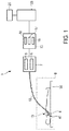
- Fig. 1 shows schematically and exemplarily an ultrasound sensing apparatus 1 for sensing an object 4.
- the object 4 is a heart of a person 13 located on a table 60.
- the object is cardiac tissue of a wall of the heart 4.
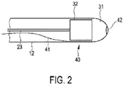
- the ultrasound sensing apparatus 1 comprises a catheter 12 with a catheter tip 40, which is schematically and exemplarily shown in more detail in Fig. 2 .
- the catheter tip 40 comprises an ultrasound unit 32 for generating an ultrasound signal depending on ultrasound waves received from the object 4.
- the catheter tip 40 further comprises a further unit 31 being an electrical unit.
- the electrical unit 31 is adapted to apply electrical energy to the cardiac tissue.
- the ultrasound unit 32 is controlled by an ultrasound control unit 5, wherein the ultrasound unit 32 and the ultrasound control unit 5 are adapted to send out ultrasound pulses into the cardiac tissue, to receive dynamic echo series after the ultrasound pulses have been reflected by the cardiac tissue and to generate an ultrasound signal depending on the received dynamic echo series.
- the ultrasound unit 32 is connected with the ultrasound control unit 5 via an electrical connection 23.
- the electrical energy application unit 31 is an ablation electrode for applying electrical RF energy to the cardiac tissue, wherein the ablation electrode 31 is connected with a sub-control unit 6 via an electrical connection 41 being, for example, a cable for controlling the ablation electrode 31.
- the ablation electrode 31 is a cap electrode provided at the tip 40 of the catheter 12 and comprises a frontal, central opening 42 for allowing the ultrasound unit 32 to sense the cardiac tissue through the opening 42.
- the sub-control unit 6 and the ultrasound control unit 5 are integrated in a control unit 7.
- the control units can be separate control units.
- the sub-control unit 6 is preferentially further adapted to control a steering of the catheter tip 40 and/or an irrigation.
- the catheter further comprises a steering element and/or an irrigation element, respectively, which are not shown in Fig. 1 and Fig. 2 .
- the different control functions can be performed by any number of control units, for example, by a single control unit or by two or more than two control units.
- the control unit 7 is adapted to operate the ultrasound unit 32 and the electrical unit 31 simultaneously, wherein the generated ultrasound signal is influenced by the electrical unit 31, i.e., in this embodiment, by the application of the RF energy.
- the generated ultrasound signal 19 is schematically and exemplarily shown in Fig. 3 .
- Fig. 3 shows in the upper part schematically and exemplarily the ultrasound energy E depending on the tissue depth d.
- the lower part of Fig. 3 shows the generated ultrasound signal 19.
- the ultrasound signal 19 shown in the lower part of Fig. 3 is an A-line, wherein the amplitude is shown depending on the tissue depth d.
- the ultrasound energy E decreases with increasing tissue depth d because of the absorption and scattering by the cardiac tissue.
- the first part A of the ultrasound signal 19 corresponds to an ultrasound energy E, which is larger than 0.
- the first part A comprises therefore information about the cardiac tissue from which the ultrasound signal 19 has been received.
- the second part B of the ultrasound signal 19 corresponds to an ultrasound energy E being substantially 0.
- the second part B of the ultrasound signal 19 does therefore not comprise information about the object.
- the first part A comprises tissue information, which is shadowed by RF interference
- the second part B does not comprise tissue information due to absorption and scattering of ultrasound energy, and only RF interference is visible in the second part B.
- TGC time-dependent amplification
- the ultrasound sensing apparatus 1 further comprises a filtering apparatus 15 for filtering the generated ultrasound signal 19.
- the filtering apparatus 15 comprises a fundamental frequency providing unit 16 for providing a fundamental frequency of the influence by the RF ablation electrode 31.
- the fundamental frequency providing unit 16 is adapted to determine the fundamental frequency by cross-correlating two consecutive sub-parts of the second part B of the ultrasound signal 19.
- the fundamental frequency providing unit 16 is adapted to fit a parabolic function to the cross-correlation and to determine the fundamental frequency depending on the maximum of the fitted parabolic function. This will in the following be described in more detail.
- Preknowledge about the frequency and about the frequency band of RF which may be obtainable from the specification of the RF generator, can improve the speed of the cross-correlation calculation, because an adequate window size can be determined as described above.
- the variable t is preferentially chosen such that t - 2W defines a sample representing RF interference only and no tissue reflections.
- the sub-parts defined in equations (1) and (3) can be upsampled and the upsampled sub-parts can be cross correlated.
- the fundamental RF frequency is preferentially determined directly from the cross correlation, without performing a parabolic fit.
- the filtering apparatus 15 further comprises a correction signal determination unit 17 for determining a correction signal being indicative of the influence of the electrical unit 31 on the ultrasound signal 19 from the second part B of the ultrasound signal 19.
- the correction signal determination unit 17 is adapted to determine a sub-part of the second part of the ultrasound signal, which corresponds to at least one cycle of the influence by the electrical unit 31, depending on the provided fundamental frequency, and to determine a sequence of the determined sub-parts of the second part of the ultrasound signal as the correction signal.
- a sub-part of the second part can be regarded as a template RF pattern from the A-line.
- This template RF pattern is chosen such that it is surely in a region of the A-line, in which only RF interference is present without tissue reflections.
- the template RF pattern may be chosen at a relatively high tissue depth being larger than, for example, 15 mm.
- the correction signal determination unit 16 is preferentially further adapted to upsample the template RF pattern by a factor of two and to apply a bi-reciprocal IIR filter, which is an interpolation filter, to the upsampled template RF pattern.
- This upsampling and filtering with the bi-reciprocal IIR filter is preferentially performed several times, in particular, four times.
- the upsampling is preferentially performed by inserting a 0 between each pair of samples of the template RF pattern, i.e. of the template RF pattern.
- the bi-reciprocal IIR filtering also known as half-band recursive filtering or Mth-band recursive filtering, is disclosed in, for example, " Efficiency in multirate and complex digital signal processing", A. W.M. van den Enden, ISBN 90-6674-650-5, Chapter 7.1 , which is herewith incorporated by reference.
- the bi-reciprocal IIR filter is adapted in such a way that aliasing does not occur and the template RF pattern is unaffected.
- the upsampling by a factor of two in a single upsampling step followed by the filtering is preferred, because it is easy to implement on Digital Signal Processors (DSPs), which can be very useful when integrating on-chip.
- DSPs Digital Signal Processors
- the upsampling can also be performed by another factor and/or another interpolation filter can be used.
- a complete RF cycle has 454 samples, if an RF frequency of 460 kHz +/- 20 kHz is assumed.
- the RF frequency and its harmonics can change during ablation. This change is not necessarily an integer number of samples, i.e., for example, the RF frequency can change from 460,000.000 Hz to 460,000.005 Hz within two consecutive RF cycles inside a single A-line.
- the template may therefore not exactly match a respective sub-part of the part A, if the correction signal is used for correcting the first part A. In order to improve the matching accuracy, a fractional shift in samples could therefore be provided.
- the correction signal determination unit 17 can further be adapted to recalculate the RF fundamental frequency to a fractional frequency in samples. For example, if the location of the maximum of the polynomially interpolated correlation is known from the above described fitting procedure, the RF fundamental frequency for the respective A-line is known. The recalculation can be performed such that the determined RF fundamental frequency fits to the upsampling by the factor of preferentially 16, which was achieved as described above by performing the upsampling by a factor of two four times. The RF fundamental frequency can be recalculated to the nearest sample, i.e. the RF fundamental frequency can be rounded to the nearest sample. For example, if the determined RF fundamental frequency is 454.05 samples, it can be recalculated to 454.0625 samples.
- the ultrasound unit control unit 5 is preferentially adapted to apply a time dependent amplification to the ultrasound signal.
- the correction signal determination unit 17 is therefore preferentially adapted to apply the same time dependent amplification to the correction signal.
- the correction signal determination unit 17 is therefore preferentially adapted to compensate the correction signal, i.e. the upsampled and filtered template RF patterns, for amplitude modification.
- the filtering apparatus 15 further comprises a correction unit 18 for correcting the first part A of the ultrasound signal 19 based on the determined correction signal for filtering the influence of the electrical unit 31 out of the ultrasound signal 19.
- the correction unit 18 is adapted to subtract the determined correction signal from the first part A of the ultrasound signal 19.
- C i ⁇ R ⁇ m ⁇ K i ⁇ R m ⁇ 1 subA denotes a corrected sub-part of the first part A comprising the samples defined by i - RmK i - R ( m -1), wherein R is the fundamental RF frequency after the floor function has been applied to the fundamental RF frequency, m varies from 0 to i / R, and i denotes the first beginning of the second part B as defined above with reference to equation (1).
- O i ⁇ Rm ... i ⁇ m ⁇ 1 subA denotes the sub-part of the first part A before being corrected
- T delay : U : UR + delay subB denotes samples of the upsamled and filtered template RF patterns forming the correction signal.
- the samples of the upsampled and filtered template RF pattern are defined by delay: U : UR+ delay, i.e. by delay, delay+U, delay+ 2U,...,UR+ delay, wherein U denotes the total upsampling factor, which is, in the above described example with four times upsampling with a factor of two, 16.
- T delay : U : UR + delay subB only each U -th sample is taken, because of the total upsamling factor U .
- the correction signal is subtracted from the original A-line data containing both, ultrasound tissue reflection and RF interference.
- Fig. 4 shows schematically and exemplarily a single A-line with RF interference.
- Fig. 5 shows schematically and exemplarily a sub-part of the second part B for illustrating the upsampling and filtering.
- the original samples are indicated by the circles, and the upsampled samples are indicated by crosses.
- the sub-part shown in Fig. 4 comprises about 2000/16 samples with respect to the original sampling, if the total upsampling factor is 16, so about a quarter of the template having 454 samples with respect to the original sampling in the above described embodiment.
- the high amplitude between 2000 and 3000 is half of the actual RF interference cycle. Whereas RF interference occurs at zero crossings, and the RF cycle is a sine, there are two almost, but not identical RF interferences per RF cycle.
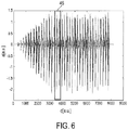
- Fig. 6 shows schematically and exemplarily a reconstructed RF interference pattern, i.e. a sequence of RF templates matching the A-line, which can be subtracted from the A-line.
- the formation of the sequence of RF templates and the subtraction is preferentially only performed for the first part A of the ultrasound signal.
- a single template RF pattern is indicated by box 45.
- the consecutive patterns forming the correction signal shown in Fig. 6 vary, because different samples of the upsampled template RF patterns are used for the subtraction in accordance with equation (6).
- the correction signal is subtracted at each point in time in the A-line, at least in the first part A of the A-line, where RF interference is occurring.
- the resulting A-lines can be stuck together to form an M-mode ultrasound image.
- Fig. 8 shows such an M-mode ultrasound image without performing the above described correction
- Fig. 9 shows the M-mode ultrasound image after having performed the correction.
- RF interference is reduced in the M-mode ultrasound image shown in Fig. 9 .
- the ultrasound sensing apparatus 1 further comprises an object influence determination unit 103 for determining the influence of the energy application on the object 4 depending on the ultrasound sensing of the object 4.
- the energy application unit 31 is adapted to ablate the object 4, wherein the object influence determination unit 103 is adapted to determine an ablation depth, which may also be regarded as being a lesion boundary, depending on the ultrasound sensing of the object 4.
- the object influence determination unit 103 is therefore adapted to receive an ultrasound signal from the ultrasound unit 5 and to determine the ablation depth depending on the received ultrasound signal.
- the object influence determination unit 103 can be adapted to determine the position of a front surface and a back surface of the heart wall from the ultrasound signal and to determine the thickness of the heart wall depending on these positions, i.e. the corresponding depth positions can be subtracted from each other to determine the thickness of the heart wall.
- the sub-control unit 6 is preferentially adapted to control the ablation electrode 31 depending on the ablation depth determined by the object influence determination unit 103. For example, the power and/or duration of applying ablation energy to the object 4 are controlled depending on the determined ablation depth.
- the object influence determination unit 103 can be adapted to determine the thickness of the heart wall, and the sub-control unit 6 can then be adapted to control the ablation electrode 31 depending on this determined thickness and the determined ablation depth.
- the sub-control unit 6 is adapted to ablate the heart wall tissue until a desired degree of transmurality of the heart wall tissue is reached, in particular, until the resulting lesion is transmural.
- the ultrasound sensing apparatus 1 is adapted to determine the thickness of the heart wall and the ablation depth repeatedly, wherein the ablation depth determination unit 103 is adapted to determine repeatedly a degree of transmurality of ablation from the determined thickness and the determined ablation depth.
- the ultrasound sensing apparatus 1 is adapted to terminate an ablation procedure, if a predetermined degree of transmurality of ablation has been reached.
- the ultrasound sensing apparatus 1 further comprises a visualization unit 20 for visualizing the ablation depth.
- the visualization unit 20 is adapted for visualizing the progression of a lesion boundary.
- the visualization is preferentially performed in real-time.
- the visualization unit 20 is preferentially adapted to show the ultrasound signal, the progression of ablation, i.e. the lesion boundary, and the front and back surface positions.
- the ultrasound sensing apparatus 1 is preferentially used in combination with a system for determining the position and/or orientation of the catheter 12, in particular, within the object 4, preferably, within a heart of a human being or an animal.
- a system for determining the position and/or orientation of the catheter 12 in particular, within the object 4, preferably, within a heart of a human being or an animal.
- an imaging system like a magnetic resonance image system or an X-ray fluoroscopy system is used for determining the position and/or orientation of the catheter.
- This imaging system is indicated by the broken line 8 shown in Fig. 1 .
- the catheter 12, in particular, the catheter tip can comprise elements for facilitating the determination of the orientation and/or position of the catheter by using the imaging system 8.
- the catheter tip can comprise a tracking coil, if the catheter tip is used within a magnetic resonance imaging system, or elements that can be identified on an X-ray image and that are shaped such that a determination of the position and/or orientation of the catheter by using an X-ray fluoroscopy system is possible.
- the catheter tip can also comprise a location sensor for determining the position and/or orientation of the catheter 12, in particular, of the catheter tip within the object 4.
- the positioning systems allows a user to position the catheter 12 within the heart, or more specifically, in the left atrium, of a patient.
- the user can position the catheter 12 in the correct position with respect to the heart wall to measure the wall thickness using the ultrasound signal generated by the ultrasound unit 11 and the object influence determination unit 103.
- the determined position of the catheter it is possible to display the thickness of the heart wall in an image of the heart. After collecting sufficient measurements, i.e. after determining the thickness of the heart wall at different locations on the heart wall, the user can then establish an ablation strategy including required power and duration depending on the determined heart wall thickness. It is also possible to use the catheter tip for tracing over the prior-performed ablation lesions for verification purposes. The continuity and depth of the lesions that have been created can be determined.
- An ultrasound signal can be influenced by an electrical unit and comprising a first part comprising information about an object from which the ultrasound signal has been received and a second part not comprising information about the object has been provided.
- a correction signal being indicative of the influence of the electrical unit on the ultrasound signal is determined from the second part of the ultrasound signal by a correction signal determination unit.
- the first part of the ultrasound signal is corrected based on the determined correction signal for filtering the influence of the electrical unit out of the ultrasound signal by a correction unit.
- Fig. 11 shows a flowchart exemplarily illustrating an embodiment of an ultrasound sensing method for sensing an object.
- an ultrasound signal is generated depending on ultrasound waves received from the object by an ultrasound unit, wherein the ultrasound unit and the further unit being an electrical unit are included in a catheter, wherein the ultrasound unit and the electrical unit operate simultaneously and wherein the generated ultrasound signal is influenced by the electrical unit and includes a first part comprising information about the object from which the ultrasound signal has been received and a second part not comprising information about the object.
- the correction signal determination unit determines a correction signal being indicative of the influence of the electrical unit on the generated ultrasound signal from the second part of the ultrasound signal and wherein the correction unit corrects the first part of the ultrasound signal based on the determined correction signal for filtering the influence of the electrical unit out of the first part of the ultrasound signal.
- the filtering apparatus preferentially provides a digital filter, based on sample rate conversion, for filtering out RF without affecting the ultrasound signal.
- This digital filter can be applied in realtime and thus allows the visualization of unperturbed ultrasound signals, which can be processed and/or shown during, for example, a medical procedure.
- both ultrasound sensing as well as ablation are performed.
- the RF signals which are very large in power, can couple indirectly onto the ultrasound wiring. This coupling can occur inside the catheter via capacitive coupling, because shielding is insufficient, or inside the heart due to conductive coupling via, for example, blood and/or saline irrigation fluid.
- RF frequencies for example, about 450 to 500 kHz are outside the band of interest in ultrasound imaging, which is generally between about 1 and 50 MHz.
- harmonics and noise are present, which can lead to interference patterns at constant intervals in the ultrasound signal where the sinusoidal shape crosses DC level. The low amplitude ultrasound signal can therefore be masked by this RF interference.
- ultrasound transducers of various frequencies are being used up to about 50 MHz.
- ultrasound transducers with a center frequency between about 20 to 30MHz are preferentially used.
- ultrasound signals are acquired at high frequency of, for example, 200 MHz per A-line.
- A-lines are typically sampled at 20-100 Hz to get an M-mode image, but higher sampling rates up to, for example, 1 kHz are also possible.
- filtering techniques can be used to filter RF, but they should work in realtime, i.e. processing of many samples per second should be possible.
- the above described filtering apparatus can be adapted to remove the RF interference from the ultrasound signal in real-time without affecting the quality of the ultrasound signal.
- the corresponding algorithm is preferentially optimized to run on specific hardware chips, in particular, on DSP processors.
- the correction signal is used for correcting the first part A of the ultrasound signal
- the correction signal can also be used to correct the entire ultrasound signal including the first part A and the second part B.
- processing steps for processing an RF template have been described, in other embodiments also other processing steps can be performed.
- a FIR implementation of a fractional delay filter can be used instead of the bi-reciprocal IIR interpolation filter.
- a standard IIR interpolation filter which is not bi-reciprocal, can be used.
- the electrical unit which influences the ultrasound signal
- the electrical unit is an ablation electrode
- the electrical unit can also be another unit such as an x-ray imaging unit or an electrical knife, which may cause interference and/or noise.
- the ultrasound sensing apparatus and the filtering apparatus are preferentially adapted to be used in tissue imaging during treatment of, for example, cardiac arrhythmias, or tumor ablation, wherein RF ablation and ultrasound imaging are combined in a single catheter or a single needle.
- the algorithm implemented in the filtering apparatus can be useful for removing also other interferences with similar characteristics as RF interferences from signals of interest.
- the ultrasound sensing apparatus is preferentially adapted as a cardiac ablation monitoring catheter which can be used in combination with an RF signal generator
- the ultrasound sensing apparatus can also be adapted to sense other objects like other parts of a person or of an animal such as another organ or vessels, or a technical object like a pipeline.
- the electrical unit can also be adapted to apply other electrical energy to the object.
- the catheter comprises an electrical unit being an ablation electrode and an ultrasound unit only
- the catheter can also comprise further elements like further sensing elements and/or further energy application elements, irrigation elements, et cetera.
- Calculations like the calculation of the fundamental RF frequency, the determination of the correction signal, the correction of the first part of the ultrasound signal depending on the correction signal, et cetera performed by one or several units or devices can be performed by any other number of units or devices.
- the determination of the fundamental RF frequency, the determination of the correction signal, the correction of the ultrasound signal depending on the determined correction signal, the determination of, for example, the ablation depth depending on the corrected ultrasound signal, et cetera can be performed by a single unit or by any other number of different units.
- the calculations and/or the control of the filtering apparatus in accordance with the filtering method and/or the control of the ultrasound sensing apparatus in accordance with the ultrasound sensing method can be implemented as program code means of a computer program and/or as dedicated hardware.
- a computer program may be stored/distributed on a suitable medium, such as an optical storage medium or a solid-state medium, supplied together with or as part of other hardware, but may also be distributed in other forms, such as via the Internet or other wired or wireless telecommunication systems.
- a suitable medium such as an optical storage medium or a solid-state medium, supplied together with or as part of other hardware, but may also be distributed in other forms, such as via the Internet or other wired or wireless telecommunication systems.
- the invention relates to a filtering apparatus for filtering an ultrasound signal, which is influenced by an electrical unit and comprises a first part including information about an object from which the ultrasound signal has been received and a second part not comprising information about the object.
- a correction signal determination unit determines a correction signal being indicative of the influence of the electrical unit on the ultrasound signal from the second part of the ultrasound signal and a correction unit corrects the first part of the ultrasound signal based on the determined correction signal for filtering the influence of the electrical unit out of the ultrasound signal. Since the correction signal is indicative of the influence of the electrical unit, wherein the correction signal is used for correcting the ultrasound signal, unwanted interference visible in the unfiltered ultrasound signal can be filtered out.
Claims (13)
- Filtereinrichtung zum Filtern eines Ultraschallsignals, wobei das Ultraschallsignal (19) durch eine elektrische Einheit beeinflusst wird und einen ersten Teil (A), der Informationen über ein Objekt (4) umfasst, von dem das Ultraschallsignal (19) empfangen worden ist, und einen zweiten Teil (B), der keine Informationen über das Objekt (4) umfasst, umfasst, dadurch gekennzeichnet, dass die Filtereinrichtung (15) Folgendes umfasst:- eine Grundfrequenzbereitstellungseinheit (16), die konfiguriert ist, eine Grundfrequenz des Einflusses durch die elektrische Einheit auf das Ultraschallsignal (19) bereitzustellen, bestimmt durch Kreuzkorrelieren von zwei aufeinanderfolgenden Sub-Teilen des zweiten Teils (B) des Ultraschallsignals (19),- eine Korrektursignalbestimmungseinheit (17), die konfiguriert ist, ein auf der Grundfrequenz basierendes Korrektursignal zu bestimmen,- eine Korrektureinheit (18), die konfiguriert ist, den ersten Teil (A) des Ultraschallsignals (19) basierend auf dem bestimmten Korrektursignal zum Filtern des Einflusses der elektrischen Einheit (31) aus dem Ultraschallsignal (19) zu korrigieren.
- Filtereinrichtung nach Anspruch 1, wobei die Korrektureinheit (18) angepasst ist, das bestimmte Korrektursignal vom ersten Teil (A) des Ultraschallsignals (19) zu subtrahieren.
- Filtereinrichtung nach Anspruch 2, wobei- die Korrektursignalbestimmungseinheit (17) angepasst ist, einen Sub-Teil des zweiten Teils des Ultraschallsignals zu bestimmen, der mindestens einem Zyklus des Einflusses durch die elektrische Einheit entspricht, je nach der bereitgestellten Grundfrequenz, und das Korrektursignal je nach dem bestimmten Sub-Teil des zweiten Teils (B) des Ultraschallsignals zu bestimmen.
- Filtereinrichtung nach Anspruch 3, wobei die Korrektursignalbestimmungseinheit (17) angepasst ist, den Sub-Teil des zweiten Teils (B) aufwärts abzutasten.
- Filtereinrichtung nach Anspruch 4, wobei die Korrektursignalbestimmungseinheit (17) angepasst ist, einen Unendliche-Impulsantwort (IIR)-Filter auf den aufwärts abgetasteten Sub-Teil des zweiten Teils (B) anzuwenden.
- Filtereinrichtung nach Anspruch 4, wobei die Korrektursignalbestimmungseinheit (17) angepasst ist, einen bireziprokalen IIR-Filter auf den Sub-Teil des zweiten Teils (B) anzuwenden.
- Filtereinrichtung nach Anspruch 4, wobei die Korrektursignalbestimmungseinheit (17) angepasst ist, die folgenden Schritte mehrere Male vorzunehmen:- Aufwärtsabtasten des Sub-Teils des zweiten Teils (B) um einen Faktor zwei,- Anwenden eines IIR-Filters auf den aufwärts abgetasteten Sub-Teil des zweiten Teils (B).
- Filtereinrichtung nach Anspruch 1, wobei eine zeitabhängige Verstärkung auf das Ultraschallsignal angewendet worden ist und wobei die Korrektursignalbestimmungseinheit (17) angepasst ist, die zeitabhängige Verstärkung auch auf das Korrektursignal anzuwenden.
- Ultraschallwahrnehmungseinrichtung zum Wahrnehmen eines Objekts, wobei die Ultraschallwahrnehmungseinrichtung (1) Folgendes umfasst:- einen Katheter (12), der eine Ultraschalleinheit (32) zum Erzeugen eines Ultraschallsignals (19) je nach von dem Objekt (4) empfangenen Ultraschallwellen und eine weitere Einheit (31), die eine elektrische Einheit ist, enthält, wobei die Ultraschalleinheit (32) und die elektrische Einheit (31) angepasst sind, gleichzeitig in Betrieb zu sein, wobei das erzeugte Ultraschallsignal (19) durch die elektrische Einheit (31) beeinflusst wird und einen ersten Teil (A), der Informationen über das Objekt (4) umfasst, von dem das Ultraschallsignal (19) empfangen worden ist, und einen zweiten Teil (B), der keine Informationen über das Objekt (4) umfasst, enthält,- eine Filtereinrichtung (15) nach Anspruch 1.
- Ultraschallwahrnehmungseinrichtung nach Anspruch 9, wobei die elektrische Einheit (31) eine Elektrode zum Anlegen von elektrischer Energie an das Objekt (4) ist.
- Filterverfahren zum Filtern eines Ultraschallsignals, wobei das Ultraschallsignal (19) durch eine elektrische Einheit beeinflusst wird und einen ersten Teil (A), der Informationen über ein Objekt (4) umfasst, von dem das Ultraschallsignal (19) empfangen worden ist, und einen zweiten Teil (B), der keine Informationen über das Objekt (4) umfasst, umfasst, dadurch gekennzeichnet, dass das Filterverfahren Folgendes umfasst:- Bereitstellen einer Grundfrequenz des Einflusses durch die elektrische Einheit auf das Ultraschallsignal (19), bestimmt durch Kreuzkorrelieren von zwei aufeinanderfolgenden Sub-Teilen des zweiten Teils (B) des Ultraschallsignals,- Bestimmen eines auf der Grundfrequenz basierenden Korrektursignal,- Korrigieren des ersten Teils (A) des Ultraschallsignals (19) basierend auf dem bestimmten Korrektursignal zum Filtern des Einflusses der elektrischen Einheit (31) aus dem Ultraschallsignal (19).
- Filtercomputerprogramm zum Filtern eines Ultraschallsignals, dadurch gekennzeichnet, dass das Filtercomputerprogramm Programmcodemittel umfasst, um zu bewirken, dass eine Filtereinrichtung nach Anspruch 1 die Schritte des Filterverfahrens nach Anspruch 11 durchführt, wenn das Filtercomputerprogramm auf einem die Filtereinrichtung steuernden Computer ausgeführt wird.
- Ultraschallwahrnehmungscomputerprogramm zum Wahrnehmen eines Objekts, dadurch gekennzeichnet, dass das Ultraschallwahrnehmungscomputerprogramm Programmcodemittel umfasst, um zu bewirken, dass eine Ultraschallwahrnehmungseinrichtung nach Anspruch 9 die folgenden Schritte durchführt, wenn das Ultraschallwahrnehmungscomputerprogramm auf einem die Ultraschallwahrnehmungseinrichtung steuernden Computer ausgeführt wird:- Erzeugen eines Ultraschallsignals (19) je nach von dem Objekt (4) empfangenen Ultraschallwellen durch eine Ultraschalleinheit (32), wobei die Ultraschalleinheit (32) und eine weitere Einheit (31), die eine elektrische Einheit ist, in einem Katheter (12) enthalten sind, wobei die Ultraschalleinheit (32) und die elektrische Einheit (31) gleichzeitig in Betrieb sind und wobei das erzeugte Ultraschallsignal (19) durch die elektrische Einheit (31) beeinflusst wird und einen ersten Teil (A), der Informationen über das Objekt (4) umfasst, von dem das Ultraschallsignal (19) empfangen worden ist, und einen zweiten Teil (B), der keine Informationen über das Objekt (4) umfasst, enthält,- die Filterschritte des Filterverfahrens nach Anspruch 11.
Priority Applications (1)
| Application Number | Priority Date | Filing Date | Title |
|---|---|---|---|
| EP11799134.9A EP2640273B1 (de) | 2010-11-18 | 2011-11-14 | Filtriervorrichtung zum filtern eines ultraschallsignals |
Applications Claiming Priority (4)
| Application Number | Priority Date | Filing Date | Title |
|---|---|---|---|
| EP10191687 | 2010-11-18 | ||
| EP11163905 | 2011-04-27 | ||
| EP11799134.9A EP2640273B1 (de) | 2010-11-18 | 2011-11-14 | Filtriervorrichtung zum filtern eines ultraschallsignals |
| PCT/IB2011/055066 WO2012066462A1 (en) | 2010-11-18 | 2011-11-14 | Filtering apparatus for filtering an ultrasound signal |
Publications (2)
| Publication Number | Publication Date |
|---|---|
| EP2640273A1 EP2640273A1 (de) | 2013-09-25 |
| EP2640273B1 true EP2640273B1 (de) | 2019-05-22 |
Family
ID=45372281
Family Applications (1)
| Application Number | Title | Priority Date | Filing Date |
|---|---|---|---|
| EP11799134.9A Active EP2640273B1 (de) | 2010-11-18 | 2011-11-14 | Filtriervorrichtung zum filtern eines ultraschallsignals |
Country Status (7)
| Country | Link |
|---|---|
| US (1) | US10226226B2 (de) |
| EP (1) | EP2640273B1 (de) |
| JP (1) | JP6085251B2 (de) |
| CN (1) | CN103209646B (de) |
| BR (1) | BR112013012334A2 (de) |
| RU (1) | RU2597133C2 (de) |
| WO (1) | WO2012066462A1 (de) |
Families Citing this family (3)
| Publication number | Priority date | Publication date | Assignee | Title |
|---|---|---|---|---|
| KR20160035418A (ko) * | 2014-09-23 | 2016-03-31 | 삼성전자주식회사 | 초음파 프로브, 초음파 영상장치, 초음파 영상장치의 제어방법 |
| EP3285078A1 (de) * | 2016-08-17 | 2018-02-21 | General Electric Technology GmbH | Verbesserungen an oder im zusammenhang mit der ortung von fehlern in stromübertragungsleitungen |
| US10656222B2 (en) * | 2016-12-14 | 2020-05-19 | Waveguide Corporation | Variable gain amplification for linearization of NMR signals |
Citations (1)
| Publication number | Priority date | Publication date | Assignee | Title |
|---|---|---|---|---|
| WO1995017131A1 (en) * | 1993-12-22 | 1995-06-29 | Monamed Medizintechnik Gmbh | Ultrasonic marked cardiac ablation catheter |
Family Cites Families (20)
| Publication number | Priority date | Publication date | Assignee | Title |
|---|---|---|---|---|
| DE69431741T2 (de) | 1993-03-12 | 2003-09-11 | Toshiba Kawasaki Kk | Vorrichtung zur medizinischen Behandlung mit Ultraschall |
| JP3373602B2 (ja) * | 1993-08-05 | 2003-02-04 | 株式会社東芝 | 超音波治療装置 |
| US5409000A (en) | 1993-09-14 | 1995-04-25 | Cardiac Pathways Corporation | Endocardial mapping and ablation system utilizing separately controlled steerable ablation catheter with ultrasonic imaging capabilities and method |
| US5497777A (en) | 1994-09-23 | 1996-03-12 | General Electric Company | Speckle noise filtering in ultrasound imaging |
| US8709007B2 (en) * | 1997-10-15 | 2014-04-29 | St. Jude Medical, Atrial Fibrillation Division, Inc. | Devices and methods for ablating cardiac tissue |
| AU2004202579A1 (en) * | 1998-11-04 | 2004-07-08 | The Johns Hopkins University | System and Method for Magnetic-resonance-guided Electrophysiologic and Ablation Procedures |
| US6701176B1 (en) | 1998-11-04 | 2004-03-02 | Johns Hopkins University School Of Medicine | Magnetic-resonance-guided imaging, electrophysiology, and ablation |
| US20050124898A1 (en) * | 2002-01-16 | 2005-06-09 | Ep Medsystems, Inc. | Method and apparatus for isolating a catheter interface |
| US6709432B2 (en) | 2002-04-26 | 2004-03-23 | Medtronic, Inc. | Ablation methods and medical apparatus using same |
| JP3744901B2 (ja) * | 2003-01-07 | 2006-02-15 | 株式会社日立製作所 | 検査装置 |
| US20050261571A1 (en) * | 2004-05-21 | 2005-11-24 | Willis Nathaniel P | 3-D ultrasound navigation during radio-frequency ablation |
| CA2576068A1 (en) | 2004-09-16 | 2006-03-23 | University Of Washington | Interference-free ultrasound imaging during hifu therapy, using software tools |
| RU2333011C1 (ru) * | 2006-10-26 | 2008-09-10 | Государственное образовательное учреждение высшего профессионального образования "Северный государственный медицинский университет" (г. Архангельск) Федерального агентства по здравоохранению и социальному развитию" (ГОУ ВПО СГМУ Росздрава) | Устройство для измельчения и аспирации сгустков крови из полости |
| EP2175780B1 (de) | 2007-08-15 | 2013-05-22 | Koninklijke Philips Electronics N.V. | Verfahren und vorrichtung zur erzeugung von bildern erwärmter zacken in der nähe von gewebeteilen |
| JP2009090104A (ja) | 2007-09-18 | 2009-04-30 | Fujifilm Corp | 超音波診断方法及び装置 |
| CN101878000A (zh) * | 2007-11-28 | 2010-11-03 | 皇家飞利浦电子股份有限公司 | 经皮针、血管内导管和其他介入式设备的超声可视化 |
| JP5459975B2 (ja) * | 2008-04-22 | 2014-04-02 | 日立アロカメディカル株式会社 | 超音波診断装置 |
| US9901321B2 (en) * | 2009-01-14 | 2018-02-27 | Koninklijke Philips N.V. | Monitoring apparatus for monitoring an ablation procedure |
| JP2010240131A (ja) * | 2009-04-06 | 2010-10-28 | Toshiba Corp | 超音波診断装置及び超音波診断装置制御方法 |
| BR112013012207B1 (pt) * | 2010-11-18 | 2018-12-18 | Koninklijke Philips N.V. | Aparelho para redução da interferência nas aplicações de ablação de radiofrequência usando monitoramento com base de ultrassom em tempo real e método de redução dainterferência nas aplicações de ablação de radiofrequência usando monitoramento com base de ultrassom em tempo real |
-
2011
- 2011-11-14 US US13/885,403 patent/US10226226B2/en active Active
- 2011-11-14 EP EP11799134.9A patent/EP2640273B1/de active Active
- 2011-11-14 JP JP2013539376A patent/JP6085251B2/ja active Active
- 2011-11-14 CN CN201180054984.6A patent/CN103209646B/zh active Active
- 2011-11-14 RU RU2013127507/14A patent/RU2597133C2/ru active
- 2011-11-14 WO PCT/IB2011/055066 patent/WO2012066462A1/en active Application Filing
- 2011-11-14 BR BR112013012334A patent/BR112013012334A2/pt not_active IP Right Cessation
Patent Citations (1)
| Publication number | Priority date | Publication date | Assignee | Title |
|---|---|---|---|---|
| WO1995017131A1 (en) * | 1993-12-22 | 1995-06-29 | Monamed Medizintechnik Gmbh | Ultrasonic marked cardiac ablation catheter |
Also Published As
| Publication number | Publication date |
|---|---|
| BR112013012334A2 (pt) | 2019-09-24 |
| RU2013127507A (ru) | 2014-12-27 |
| JP6085251B2 (ja) | 2017-02-22 |
| RU2597133C2 (ru) | 2016-09-10 |
| WO2012066462A1 (en) | 2012-05-24 |
| CN103209646B (zh) | 2015-09-09 |
| EP2640273A1 (de) | 2013-09-25 |
| JP2014505498A (ja) | 2014-03-06 |
| US20130245440A1 (en) | 2013-09-19 |
| CN103209646A (zh) | 2013-07-17 |
| US10226226B2 (en) | 2019-03-12 |
Similar Documents
| Publication | Publication Date | Title |
|---|---|---|
| US11445998B2 (en) | System and method of adventitial tissue characterization | |
| JP5972258B2 (ja) | 撮像システム、および、生物学的構造の画像を含む超音波画像を生成するための超音波機械の動作の制御方法 | |
| JP5680654B2 (ja) | 超音波診断装置及び超音波画像表示方法 | |
| JP6366591B2 (ja) | 空間形状決定器具 | |
| US9693754B2 (en) | Imaging processing systems and methods | |
| EP2827776B1 (de) | Bildgebungssystem zur abbildung eines sich periodisch bewegenden objekts | |
| JP2006510454A (ja) | 解剖学的目標物の超音波位置特定 | |
| EP3700450A1 (de) | Bestimmung des kontaktes eines ballonkatheters mit einer anatomie mittels ultraschall | |
| EP2827779B1 (de) | Bildgebungssystem zur abbildung eines sich periodisch bewegenden objekts | |
| CN106232019B (zh) | 接触确定装置 | |
| EP2640273B1 (de) | Filtriervorrichtung zum filtern eines ultraschallsignals | |
| US20220395333A1 (en) | Co-registration of intravascular data and multi-segment vasculature, and associated devices, systems, and methods | |
| EP1055133A1 (de) | Ultraschallverfahren und gerät zur bestimmung der position einer gewebegrenzfläche und der absolute radius einer arterie | |
| US20200196890A1 (en) | Electrophysiological ripple mapping visualization method | |
| JP4621476B2 (ja) | 超音波診断装置 | |
| US20240050073A1 (en) | Ultrasound imaging of cardiac anatomy using doppler analysis | |
| US11497473B2 (en) | Ultrasound cardiac processing | |
| EP4275612A1 (de) | Verbesserungen in ultraschallbasierten blutflussgeschwindigkeitsmessungen | |
| CN110167448B (zh) | 基于时间的参数对比增强超声成像系统和方法 | |
| WO2023088760A1 (en) | Improvements in ultrasound based blood flow velocity measurements | |
| Patil et al. | A method to detect tortuosity of vessel using non imaging ultrasound approach in carotid structure |
Legal Events
| Date | Code | Title | Description |
|---|---|---|---|
| PUAI | Public reference made under article 153(3) epc to a published international application that has entered the european phase |
Free format text: ORIGINAL CODE: 0009012 |
|
| 17P | Request for examination filed |
Effective date: 20130618 |
|
| AK | Designated contracting states |
Kind code of ref document: A1 Designated state(s): AL AT BE BG CH CY CZ DE DK EE ES FI FR GB GR HR HU IE IS IT LI LT LU LV MC MK MT NL NO PL PT RO RS SE SI SK SM TR |
|
| DAX | Request for extension of the european patent (deleted) | ||
| 17Q | First examination report despatched |
Effective date: 20151023 |
|
| STAA | Information on the status of an ep patent application or granted ep patent |
Free format text: STATUS: EXAMINATION IS IN PROGRESS |
|
| GRAP | Despatch of communication of intention to grant a patent |
Free format text: ORIGINAL CODE: EPIDOSNIGR1 |
|
| STAA | Information on the status of an ep patent application or granted ep patent |
Free format text: STATUS: GRANT OF PATENT IS INTENDED |
|
| INTG | Intention to grant announced |
Effective date: 20181207 |
|
| GRAS | Grant fee paid |
Free format text: ORIGINAL CODE: EPIDOSNIGR3 |
|
| GRAA | (expected) grant |
Free format text: ORIGINAL CODE: 0009210 |
|
| STAA | Information on the status of an ep patent application or granted ep patent |
Free format text: STATUS: THE PATENT HAS BEEN GRANTED |
|
| AK | Designated contracting states |
Kind code of ref document: B1 Designated state(s): AL AT BE BG CH CY CZ DE DK EE ES FI FR GB GR HR HU IE IS IT LI LT LU LV MC MK MT NL NO PL PT RO RS SE SI SK SM TR |
|
| REG | Reference to a national code |
Ref country code: GB Ref legal event code: FG4D |
|
| REG | Reference to a national code |
Ref country code: CH Ref legal event code: EP |
|
| REG | Reference to a national code |
Ref country code: IE Ref legal event code: FG4D |
|
| REG | Reference to a national code |
Ref country code: DE Ref legal event code: R096 Ref document number: 602011059228 Country of ref document: DE |
|
| REG | Reference to a national code |
Ref country code: AT Ref legal event code: REF Ref document number: 1135110 Country of ref document: AT Kind code of ref document: T Effective date: 20190615 |
|
| REG | Reference to a national code |
Ref country code: NL Ref legal event code: MP Effective date: 20190522 |
|
| REG | Reference to a national code |
Ref country code: LT Ref legal event code: MG4D |
|
| PG25 | Lapsed in a contracting state [announced via postgrant information from national office to epo] |
Ref country code: NL Free format text: LAPSE BECAUSE OF FAILURE TO SUBMIT A TRANSLATION OF THE DESCRIPTION OR TO PAY THE FEE WITHIN THE PRESCRIBED TIME-LIMIT Effective date: 20190522 Ref country code: SE Free format text: LAPSE BECAUSE OF FAILURE TO SUBMIT A TRANSLATION OF THE DESCRIPTION OR TO PAY THE FEE WITHIN THE PRESCRIBED TIME-LIMIT Effective date: 20190522 Ref country code: HR Free format text: LAPSE BECAUSE OF FAILURE TO SUBMIT A TRANSLATION OF THE DESCRIPTION OR TO PAY THE FEE WITHIN THE PRESCRIBED TIME-LIMIT Effective date: 20190522 Ref country code: AL Free format text: LAPSE BECAUSE OF FAILURE TO SUBMIT A TRANSLATION OF THE DESCRIPTION OR TO PAY THE FEE WITHIN THE PRESCRIBED TIME-LIMIT Effective date: 20190522 Ref country code: NO Free format text: LAPSE BECAUSE OF FAILURE TO SUBMIT A TRANSLATION OF THE DESCRIPTION OR TO PAY THE FEE WITHIN THE PRESCRIBED TIME-LIMIT Effective date: 20190822 Ref country code: PT Free format text: LAPSE BECAUSE OF FAILURE TO SUBMIT A TRANSLATION OF THE DESCRIPTION OR TO PAY THE FEE WITHIN THE PRESCRIBED TIME-LIMIT Effective date: 20190922 Ref country code: FI Free format text: LAPSE BECAUSE OF FAILURE TO SUBMIT A TRANSLATION OF THE DESCRIPTION OR TO PAY THE FEE WITHIN THE PRESCRIBED TIME-LIMIT Effective date: 20190522 Ref country code: LT Free format text: LAPSE BECAUSE OF FAILURE TO SUBMIT A TRANSLATION OF THE DESCRIPTION OR TO PAY THE FEE WITHIN THE PRESCRIBED TIME-LIMIT Effective date: 20190522 Ref country code: ES Free format text: LAPSE BECAUSE OF FAILURE TO SUBMIT A TRANSLATION OF THE DESCRIPTION OR TO PAY THE FEE WITHIN THE PRESCRIBED TIME-LIMIT Effective date: 20190522 |
|
| PG25 | Lapsed in a contracting state [announced via postgrant information from national office to epo] |
Ref country code: GR Free format text: LAPSE BECAUSE OF FAILURE TO SUBMIT A TRANSLATION OF THE DESCRIPTION OR TO PAY THE FEE WITHIN THE PRESCRIBED TIME-LIMIT Effective date: 20190823 Ref country code: BG Free format text: LAPSE BECAUSE OF FAILURE TO SUBMIT A TRANSLATION OF THE DESCRIPTION OR TO PAY THE FEE WITHIN THE PRESCRIBED TIME-LIMIT Effective date: 20190822 Ref country code: RS Free format text: LAPSE BECAUSE OF FAILURE TO SUBMIT A TRANSLATION OF THE DESCRIPTION OR TO PAY THE FEE WITHIN THE PRESCRIBED TIME-LIMIT Effective date: 20190522 Ref country code: LV Free format text: LAPSE BECAUSE OF FAILURE TO SUBMIT A TRANSLATION OF THE DESCRIPTION OR TO PAY THE FEE WITHIN THE PRESCRIBED TIME-LIMIT Effective date: 20190522 |
|
| REG | Reference to a national code |
Ref country code: AT Ref legal event code: MK05 Ref document number: 1135110 Country of ref document: AT Kind code of ref document: T Effective date: 20190522 |
|
| PG25 | Lapsed in a contracting state [announced via postgrant information from national office to epo] |
Ref country code: DK Free format text: LAPSE BECAUSE OF FAILURE TO SUBMIT A TRANSLATION OF THE DESCRIPTION OR TO PAY THE FEE WITHIN THE PRESCRIBED TIME-LIMIT Effective date: 20190522 Ref country code: AT Free format text: LAPSE BECAUSE OF FAILURE TO SUBMIT A TRANSLATION OF THE DESCRIPTION OR TO PAY THE FEE WITHIN THE PRESCRIBED TIME-LIMIT Effective date: 20190522 Ref country code: EE Free format text: LAPSE BECAUSE OF FAILURE TO SUBMIT A TRANSLATION OF THE DESCRIPTION OR TO PAY THE FEE WITHIN THE PRESCRIBED TIME-LIMIT Effective date: 20190522 Ref country code: RO Free format text: LAPSE BECAUSE OF FAILURE TO SUBMIT A TRANSLATION OF THE DESCRIPTION OR TO PAY THE FEE WITHIN THE PRESCRIBED TIME-LIMIT Effective date: 20190522 Ref country code: CZ Free format text: LAPSE BECAUSE OF FAILURE TO SUBMIT A TRANSLATION OF THE DESCRIPTION OR TO PAY THE FEE WITHIN THE PRESCRIBED TIME-LIMIT Effective date: 20190522 Ref country code: SK Free format text: LAPSE BECAUSE OF FAILURE TO SUBMIT A TRANSLATION OF THE DESCRIPTION OR TO PAY THE FEE WITHIN THE PRESCRIBED TIME-LIMIT Effective date: 20190522 |
|
| REG | Reference to a national code |
Ref country code: DE Ref legal event code: R097 Ref document number: 602011059228 Country of ref document: DE |
|
| PG25 | Lapsed in a contracting state [announced via postgrant information from national office to epo] |
Ref country code: SM Free format text: LAPSE BECAUSE OF FAILURE TO SUBMIT A TRANSLATION OF THE DESCRIPTION OR TO PAY THE FEE WITHIN THE PRESCRIBED TIME-LIMIT Effective date: 20190522 Ref country code: IT Free format text: LAPSE BECAUSE OF FAILURE TO SUBMIT A TRANSLATION OF THE DESCRIPTION OR TO PAY THE FEE WITHIN THE PRESCRIBED TIME-LIMIT Effective date: 20190522 |
|
| RAP2 | Party data changed (patent owner data changed or rights of a patent transferred) |
Owner name: KONINKLIJKE PHILIPS N.V. |
|
| PLBE | No opposition filed within time limit |
Free format text: ORIGINAL CODE: 0009261 |
|
| STAA | Information on the status of an ep patent application or granted ep patent |
Free format text: STATUS: NO OPPOSITION FILED WITHIN TIME LIMIT |
|
| PG25 | Lapsed in a contracting state [announced via postgrant information from national office to epo] |
Ref country code: TR Free format text: LAPSE BECAUSE OF FAILURE TO SUBMIT A TRANSLATION OF THE DESCRIPTION OR TO PAY THE FEE WITHIN THE PRESCRIBED TIME-LIMIT Effective date: 20190522 |
|
| 26N | No opposition filed |
Effective date: 20200225 |
|
| PG25 | Lapsed in a contracting state [announced via postgrant information from national office to epo] |
Ref country code: PL Free format text: LAPSE BECAUSE OF FAILURE TO SUBMIT A TRANSLATION OF THE DESCRIPTION OR TO PAY THE FEE WITHIN THE PRESCRIBED TIME-LIMIT Effective date: 20190522 |
|
| PG25 | Lapsed in a contracting state [announced via postgrant information from national office to epo] |
Ref country code: SI Free format text: LAPSE BECAUSE OF FAILURE TO SUBMIT A TRANSLATION OF THE DESCRIPTION OR TO PAY THE FEE WITHIN THE PRESCRIBED TIME-LIMIT Effective date: 20190522 |
|
| REG | Reference to a national code |
Ref country code: CH Ref legal event code: PL |
|
| PG25 | Lapsed in a contracting state [announced via postgrant information from national office to epo] |
Ref country code: CH Free format text: LAPSE BECAUSE OF NON-PAYMENT OF DUE FEES Effective date: 20191130 Ref country code: LU Free format text: LAPSE BECAUSE OF NON-PAYMENT OF DUE FEES Effective date: 20191114 Ref country code: LI Free format text: LAPSE BECAUSE OF NON-PAYMENT OF DUE FEES Effective date: 20191130 Ref country code: MC Free format text: LAPSE BECAUSE OF FAILURE TO SUBMIT A TRANSLATION OF THE DESCRIPTION OR TO PAY THE FEE WITHIN THE PRESCRIBED TIME-LIMIT Effective date: 20190522 |
|
| REG | Reference to a national code |
Ref country code: BE Ref legal event code: MM Effective date: 20191130 |
|
| PG25 | Lapsed in a contracting state [announced via postgrant information from national office to epo] |
Ref country code: IE Free format text: LAPSE BECAUSE OF NON-PAYMENT OF DUE FEES Effective date: 20191114 |
|
| PG25 | Lapsed in a contracting state [announced via postgrant information from national office to epo] |
Ref country code: BE Free format text: LAPSE BECAUSE OF NON-PAYMENT OF DUE FEES Effective date: 20191130 |
|
| PG25 | Lapsed in a contracting state [announced via postgrant information from national office to epo] |
Ref country code: CY Free format text: LAPSE BECAUSE OF FAILURE TO SUBMIT A TRANSLATION OF THE DESCRIPTION OR TO PAY THE FEE WITHIN THE PRESCRIBED TIME-LIMIT Effective date: 20190522 |
|
| PG25 | Lapsed in a contracting state [announced via postgrant information from national office to epo] |
Ref country code: IS Free format text: LAPSE BECAUSE OF FAILURE TO SUBMIT A TRANSLATION OF THE DESCRIPTION OR TO PAY THE FEE WITHIN THE PRESCRIBED TIME-LIMIT Effective date: 20190922 |
|
| PG25 | Lapsed in a contracting state [announced via postgrant information from national office to epo] |
Ref country code: MT Free format text: LAPSE BECAUSE OF FAILURE TO SUBMIT A TRANSLATION OF THE DESCRIPTION OR TO PAY THE FEE WITHIN THE PRESCRIBED TIME-LIMIT Effective date: 20190522 Ref country code: HU Free format text: LAPSE BECAUSE OF FAILURE TO SUBMIT A TRANSLATION OF THE DESCRIPTION OR TO PAY THE FEE WITHIN THE PRESCRIBED TIME-LIMIT; INVALID AB INITIO Effective date: 20111114 |
|
| PG25 | Lapsed in a contracting state [announced via postgrant information from national office to epo] |
Ref country code: MK Free format text: LAPSE BECAUSE OF FAILURE TO SUBMIT A TRANSLATION OF THE DESCRIPTION OR TO PAY THE FEE WITHIN THE PRESCRIBED TIME-LIMIT Effective date: 20190522 |
|
| PGFP | Annual fee paid to national office [announced via postgrant information from national office to epo] |
Ref country code: GB Payment date: 20231121 Year of fee payment: 13 |
|
| PGFP | Annual fee paid to national office [announced via postgrant information from national office to epo] |
Ref country code: FR Payment date: 20231123 Year of fee payment: 13 Ref country code: DE Payment date: 20231127 Year of fee payment: 13 |