EP2639868A1 - Plaque bipolaire ainsi que cellule électrochimique dotée d'une telle plaque bipolaire - Google Patents
Plaque bipolaire ainsi que cellule électrochimique dotée d'une telle plaque bipolaire Download PDFInfo
- Publication number
- EP2639868A1 EP2639868A1 EP12159142.4A EP12159142A EP2639868A1 EP 2639868 A1 EP2639868 A1 EP 2639868A1 EP 12159142 A EP12159142 A EP 12159142A EP 2639868 A1 EP2639868 A1 EP 2639868A1
- Authority
- EP
- European Patent Office
- Prior art keywords
- elevations
- flow
- plate
- bipolar plate
- bipolar
- Prior art date
- Legal status (The legal status is an assumption and is not a legal conclusion. Google has not performed a legal analysis and makes no representation as to the accuracy of the status listed.)
- Withdrawn
Links
Images


Classifications
-
- H—ELECTRICITY
- H01—ELECTRIC ELEMENTS
- H01M—PROCESSES OR MEANS, e.g. BATTERIES, FOR THE DIRECT CONVERSION OF CHEMICAL ENERGY INTO ELECTRICAL ENERGY
- H01M8/00—Fuel cells; Manufacture thereof
- H01M8/02—Details
- H01M8/0202—Collectors; Separators, e.g. bipolar separators; Interconnectors
- H01M8/0204—Non-porous and characterised by the material
- H01M8/0223—Composites
- H01M8/0228—Composites in the form of layered or coated products
-
- H—ELECTRICITY
- H01—ELECTRIC ELEMENTS
- H01M—PROCESSES OR MEANS, e.g. BATTERIES, FOR THE DIRECT CONVERSION OF CHEMICAL ENERGY INTO ELECTRICAL ENERGY
- H01M8/00—Fuel cells; Manufacture thereof
- H01M8/02—Details
- H01M8/0202—Collectors; Separators, e.g. bipolar separators; Interconnectors
- H01M8/0247—Collectors; Separators, e.g. bipolar separators; Interconnectors characterised by the form
- H01M8/0254—Collectors; Separators, e.g. bipolar separators; Interconnectors characterised by the form corrugated or undulated
-
- H—ELECTRICITY
- H01—ELECTRIC ELEMENTS
- H01M—PROCESSES OR MEANS, e.g. BATTERIES, FOR THE DIRECT CONVERSION OF CHEMICAL ENERGY INTO ELECTRICAL ENERGY
- H01M8/00—Fuel cells; Manufacture thereof
- H01M8/02—Details
- H01M8/0202—Collectors; Separators, e.g. bipolar separators; Interconnectors
- H01M8/0258—Collectors; Separators, e.g. bipolar separators; Interconnectors characterised by the configuration of channels, e.g. by the flow field of the reactant or coolant
- H01M8/0263—Collectors; Separators, e.g. bipolar separators; Interconnectors characterised by the configuration of channels, e.g. by the flow field of the reactant or coolant having meandering or serpentine paths
-
- H—ELECTRICITY
- H01—ELECTRIC ELEMENTS
- H01M—PROCESSES OR MEANS, e.g. BATTERIES, FOR THE DIRECT CONVERSION OF CHEMICAL ENERGY INTO ELECTRICAL ENERGY
- H01M8/00—Fuel cells; Manufacture thereof
- H01M8/02—Details
- H01M8/0202—Collectors; Separators, e.g. bipolar separators; Interconnectors
- H01M8/0267—Collectors; Separators, e.g. bipolar separators; Interconnectors having heating or cooling means, e.g. heaters or coolant flow channels
-
- H—ELECTRICITY
- H01—ELECTRIC ELEMENTS
- H01M—PROCESSES OR MEANS, e.g. BATTERIES, FOR THE DIRECT CONVERSION OF CHEMICAL ENERGY INTO ELECTRICAL ENERGY
- H01M8/00—Fuel cells; Manufacture thereof
- H01M8/04—Auxiliary arrangements, e.g. for control of pressure or for circulation of fluids
- H01M8/04007—Auxiliary arrangements, e.g. for control of pressure or for circulation of fluids related to heat exchange
- H01M8/04029—Heat exchange using liquids
-
- H—ELECTRICITY
- H01—ELECTRIC ELEMENTS
- H01M—PROCESSES OR MEANS, e.g. BATTERIES, FOR THE DIRECT CONVERSION OF CHEMICAL ENERGY INTO ELECTRICAL ENERGY
- H01M8/00—Fuel cells; Manufacture thereof
- H01M8/10—Fuel cells with solid electrolytes
- H01M8/1016—Fuel cells with solid electrolytes characterised by the electrolyte material
- H01M8/1018—Polymeric electrolyte materials
-
- H—ELECTRICITY
- H01—ELECTRIC ELEMENTS
- H01M—PROCESSES OR MEANS, e.g. BATTERIES, FOR THE DIRECT CONVERSION OF CHEMICAL ENERGY INTO ELECTRICAL ENERGY
- H01M8/00—Fuel cells; Manufacture thereof
- H01M8/10—Fuel cells with solid electrolytes
- H01M2008/1095—Fuel cells with polymeric electrolytes
-
- H—ELECTRICITY
- H01—ELECTRIC ELEMENTS
- H01M—PROCESSES OR MEANS, e.g. BATTERIES, FOR THE DIRECT CONVERSION OF CHEMICAL ENERGY INTO ELECTRICAL ENERGY
- H01M8/00—Fuel cells; Manufacture thereof
- H01M8/02—Details
- H01M8/0202—Collectors; Separators, e.g. bipolar separators; Interconnectors
-
- H—ELECTRICITY
- H01—ELECTRIC ELEMENTS
- H01M—PROCESSES OR MEANS, e.g. BATTERIES, FOR THE DIRECT CONVERSION OF CHEMICAL ENERGY INTO ELECTRICAL ENERGY
- H01M8/00—Fuel cells; Manufacture thereof
- H01M8/02—Details
- H01M8/0202—Collectors; Separators, e.g. bipolar separators; Interconnectors
- H01M8/0247—Collectors; Separators, e.g. bipolar separators; Interconnectors characterised by the form
-
- H—ELECTRICITY
- H01—ELECTRIC ELEMENTS
- H01M—PROCESSES OR MEANS, e.g. BATTERIES, FOR THE DIRECT CONVERSION OF CHEMICAL ENERGY INTO ELECTRICAL ENERGY
- H01M8/00—Fuel cells; Manufacture thereof
- H01M8/02—Details
- H01M8/0202—Collectors; Separators, e.g. bipolar separators; Interconnectors
- H01M8/0258—Collectors; Separators, e.g. bipolar separators; Interconnectors characterised by the configuration of channels, e.g. by the flow field of the reactant or coolant
- H01M8/0265—Collectors; Separators, e.g. bipolar separators; Interconnectors characterised by the configuration of channels, e.g. by the flow field of the reactant or coolant the reactant or coolant channels having varying cross sections
-
- Y—GENERAL TAGGING OF NEW TECHNOLOGICAL DEVELOPMENTS; GENERAL TAGGING OF CROSS-SECTIONAL TECHNOLOGIES SPANNING OVER SEVERAL SECTIONS OF THE IPC; TECHNICAL SUBJECTS COVERED BY FORMER USPC CROSS-REFERENCE ART COLLECTIONS [XRACs] AND DIGESTS
- Y02—TECHNOLOGIES OR APPLICATIONS FOR MITIGATION OR ADAPTATION AGAINST CLIMATE CHANGE
- Y02E—REDUCTION OF GREENHOUSE GAS [GHG] EMISSIONS, RELATED TO ENERGY GENERATION, TRANSMISSION OR DISTRIBUTION
- Y02E60/00—Enabling technologies; Technologies with a potential or indirect contribution to GHG emissions mitigation
- Y02E60/30—Hydrogen technology
- Y02E60/50—Fuel cells
Definitions
- the invention relates to a bipolar plate for electrochemical cells and an electrochemical cell, in particular a fuel cell, with such a bipolar plate.
- Electrochemical cells are well known and are divided into galvanic cells and electrolysis cells.
- An electrolytic cell is a device in which an electric current enforces a chemical reaction, wherein at least a portion of electrical energy is converted into chemical energy.
- a galvanic cell is a device - complementary to the electrolytic cell - for the spontaneous conversion of chemical into electrical energy.
- a known device of such a galvanic cell is a fuel cell, for example a PEM fuel cell (proton exchange membrane - fuel cell or polymer electrolyte membrane - fuel cell).
- Fuel cells are becoming increasingly important in forward-looking concepts for energy production.
- low-temperature fuel cells based on polymer electrolyte membrane (PEM) technology are being discussed as environmentally friendly and efficient energy converters for portable, mobile and stationary applications, and are already finding their first commercial uses.
- the essential element of a PEM single cell is a membrane electrode unit. This consists of two electrodes (an anode and a cathode) and an electrolyte membrane located between the two electrodes. Between the electrodes and the electrolyte membrane is a catalyst layer in which the important physical and electrochemical processes, such as adsorption of hydrogen and oxygen on the catalyst, release and uptake of electrons and the formation of water on the cathode side by combination of protons diffused through the membrane and (reduced) oxygen.
- the electrodes are located on the side facing away from the electrolyte membrane or catalyst layer in contact with a respective so-called bipolar plate.
- This component has the task to separate the individual fuel cells (media side), to provide flow of current in the cell stack and to remove the heat of reaction.
- the bipolar plates consist of an electrically conductive material, which must have a low contact resistance to the electrodes.
- a bipolar plate is eg in the WO 2004/107486 A1 described.
- the separator or bipolar plate comprises two profiled plate elements which come into contact with one another and between which a fluid or flow space for the coolant is formed.
- the plate elements have a plurality of symmetrical on the surface of the plate elements arranged embossments in the manner of round depressions.
- the embossments of both plate elements are offset relative to each other. Characteristic of such bipolar plates are relatively low flow velocities and a not always optimal distribution of the coolant in the flow space between the plate elements.
- the invention has the object of enabling a particularly uniform flow through a bipolar plate for an electrochemical cell.
- an electrochemical cell in particular a fuel cell, with such a bipolar plate.
- the advantages and preferred embodiments set forth below with regard to the bipolar plate can be transferred analogously to the electrochemical cell.
- the invention is based on the consideration of selectively guiding the flow direction of the coolant by modifying the course of the flow channels between the two plate elements by the geometry of the first and second elevations.
- the flow channels are narrowed or blocked at selected locations, so that the coolant forcibly flows around these locations and thereby a better distribution of the coolant is achieved in the entire network of flow channels.
- the term "geometry of the elevations" hereby means the size and / or the shape of the elevations.
- the majority of the elevations on the plate elements represent the first elevations, as they are formed by default in such plate elements in the context of bipolar plates for electrochemical cells. Elevations that differ in size and / or shape from the first surveys are referred to as second surveys.
- Such a bipolar plate is characterized by a better gas discharge or a homogeneous cooling characteristic over the entire surface.
- the second elevations are designed smaller than the first elevations, so that the flow channels are narrowed or interrupted in the region of the second elevations.
- a restriction or interruption of the flow channels is achieved in that the openings of the second protrusions, which are also smaller than the openings of the first protrusions, only slightly or not overlap the openings of the opposite, offset elevations of the other plate member. Due to the constrictions and interruptions of some of the flow channels, an increased flow velocity is achieved in the flow-through flow channels. This ensures that the flow medium flows at an increased speed through the otherwise difficult to reach areas.
- the coolant flows on the direct path or along an imaginary connection line between the flow inlet and the flow outlet, and regions which are farther away from the connection line are flooded less well.
- the connection line is defined here as the shortest path between the flow inlet and the flow outlet of the electrochemical cell and essentially coincides with a main flow direction of the coolant.
- the second protrusions are provided in the region of the connecting line between the flow inlet and the flow outlet in order to divert the coolant to the regions away from the main flow direction.
- are also off the connecting line between the flow inlet and the flow outlet only first bumps are provided, through which a bypass flow is generated in order to avoid regions of low flow velocity in the deflection regions.
- At least one group of two or more spatially close second elevations is formed.
- the at least one group comprises two or more second elevations arranged directly next to each other.
- the at least one group is formed by an alternating sequence of first and second elevations, so that the second elevations are not positioned directly next to one another, but a first elevation is arranged between each two second elevations.
- a particularly good cooling characteristic is achieved by the coolant is guided serpentine in the flow space between the flow inlet and the flow outlet.
- a simplest form of serpentine guide is achieved by preferably providing at least two sets of second bumps, one closer to the flow inlet and one closer to the flow outlet. Closer to the flow inlet, this means that when the surface of the plate members is divided into two equal halves by a center line between the flow inlet and the flow outlet, this group is completely or at least mostly in the half associated with the flow inlet. The same applies to the other group, but with reference to the flow outlet.
- the second elevations are preferably distributed symmetrically.
- the plate element which has only the first elevations, can be a standard plate element, as it is used today in fuel cells. Since only one of two plate elements is modified, the manufacturing costs for a bipolar plate described above are kept as low as possible.
- the elevations are embossed in the respective plate element, so that both the first and the second elevations are formed by embossing in the material of the plate member.
- the first bumps are formed as nubs with a circular cross-section.
- each two adjacent knobs have the same distance from each other.
- the second elevations are formed as nubs with a semicircular cross-section.
- the second elevations have in particular the same radius as the first elevations, but due to their semicircular cross-section they are only half the size of the first elevations.
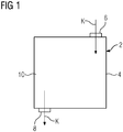
- FIG. 1 a bipolar plate 2 is shown for a fuel cell, not shown in detail in a schematic plan view.
- a flow space 4 for coolant K in this case cooling water
- a flow inlet 6 K of cooling water is introduced into the flow space 4 and passed through a flow outlet 8.
- the flow space 4 is limited on its two flat sides by two plate elements, of which in FIG. 1 only an upper plate element 10 is visible.
- the plate element 10 is metallic.
- the surface of the plate member 10 also has a profiling, which in FIG. 1 not shown in detail.
- FIG. 3 The structure and the arrangement of the plate elements 10, 12 according to the prior art is in 2 and FIG. 3 shown.
- the plate elements 10, 12 is a plurality of knob-shaped elevations 14, also referred to as first surveys, embossed.
- FIG. 2 For example, the protrusions 14 of the upper plate member 10 are shown with a solid line, while the protrusions 14 of the lower plate member 12 are indicated by a dashed line.
- each of the plate elements 10, 12 has a contact plane 16, from which the elevations 14 protrude outward. The contact between the two plate elements 10, 12 takes place in the contact plane 16.
- the impressed in the material of the plate elements 10, 12 elevations or nubs 14 are enclosed by three sides, however, to the contact plane 16, they have an opening 18.
- the knobs 14 are offset from each other.
- the openings 18 partially overlap, so that run through the elevations 14 in the flow space 4, a plurality of discrete flow channels 20 for the cooling water K.
- FIG. 2 Furthermore, a main flow direction 22 is shown, which is represented substantially by the connection line between the flow inlet 6 and the flow outlet 8 ,.
- elevations 24 are modified, so that the course of the flow channels 20 between the plate elements 10, 12 is changed. This is off FIG. 4 seen.
- second elevations 24 are provided, which in the exemplary embodiment shown have a semicircular cross section.
- two groups 26 of three each, immediately juxtaposed second elevations 24 are provided.
- the two groups 26 lie in the region of the main flow direction 22, ie they are in the region of the connecting line between the flow inlet 6 and the flow outlet 8.
- the groups 26 are aligned in particular approximately transversely to the main flow direction 22, usually closes each provided with the reference numeral 26 block an angle between 0 ° and 90 ° with the main flow direction 22 a.
- One of the groups 26 is positioned closer to the flow inlet 6, and the other group 26 is positioned closer to the flow outlet 8. This results in an offset of the two groups 26 with respect to a vertical center line V.
- the two groups 26 are located on different sides of a horizontal center line H between the flow inlet 6 and the flow outlet 8.
- the groups 26 are in particular rotationally symmetric with respect to an intersection of the center lines H and V arranged.
Landscapes
- Chemical & Material Sciences (AREA)
- Life Sciences & Earth Sciences (AREA)
- Engineering & Computer Science (AREA)
- Manufacturing & Machinery (AREA)
- Sustainable Development (AREA)
- Sustainable Energy (AREA)
- Chemical Kinetics & Catalysis (AREA)
- Electrochemistry (AREA)
- General Chemical & Material Sciences (AREA)
- Composite Materials (AREA)
- Fuel Cell (AREA)
Priority Applications (7)
| Application Number | Priority Date | Filing Date | Title |
|---|---|---|---|
| EP12159142.4A EP2639868A1 (fr) | 2012-03-13 | 2012-03-13 | Plaque bipolaire ainsi que cellule électrochimique dotée d'une telle plaque bipolaire |
| KR1020147025231A KR101875520B1 (ko) | 2012-03-13 | 2012-11-29 | 양극 플레이트 및 그러한 양극 플레이트를 포함하는 전기화학 전지 |
| PCT/EP2012/073917 WO2013135322A1 (fr) | 2012-03-13 | 2012-11-29 | Plaque bipolaire et cellule électrochimique comportant une telle plaque bipolaire |
| AU2012372903A AU2012372903A1 (en) | 2012-03-13 | 2012-11-29 | Bipolar plate and electrochemical cell comprising such a bipolar plate |
| RU2014141063A RU2014141063A (ru) | 2012-03-13 | 2012-11-29 | Биполярная пластина, а также электрохимическая ячейка с такой биполярной пластиной |
| US14/385,411 US9595724B2 (en) | 2012-03-13 | 2012-11-29 | Bipolar plate and electrochemical cell comprising such a bipolar plate |
| EP12799536.3A EP2826086B1 (fr) | 2012-03-13 | 2012-11-29 | Plaque bipolaire ainsi que cellule électrochimique dotée d'une telle plaque bipolaire |
Applications Claiming Priority (1)
| Application Number | Priority Date | Filing Date | Title |
|---|---|---|---|
| EP12159142.4A EP2639868A1 (fr) | 2012-03-13 | 2012-03-13 | Plaque bipolaire ainsi que cellule électrochimique dotée d'une telle plaque bipolaire |
Publications (1)
| Publication Number | Publication Date |
|---|---|
| EP2639868A1 true EP2639868A1 (fr) | 2013-09-18 |
Family
ID=47356020
Family Applications (2)
| Application Number | Title | Priority Date | Filing Date |
|---|---|---|---|
| EP12159142.4A Withdrawn EP2639868A1 (fr) | 2012-03-13 | 2012-03-13 | Plaque bipolaire ainsi que cellule électrochimique dotée d'une telle plaque bipolaire |
| EP12799536.3A Active EP2826086B1 (fr) | 2012-03-13 | 2012-11-29 | Plaque bipolaire ainsi que cellule électrochimique dotée d'une telle plaque bipolaire |
Family Applications After (1)
| Application Number | Title | Priority Date | Filing Date |
|---|---|---|---|
| EP12799536.3A Active EP2826086B1 (fr) | 2012-03-13 | 2012-11-29 | Plaque bipolaire ainsi que cellule électrochimique dotée d'une telle plaque bipolaire |
Country Status (6)
| Country | Link |
|---|---|
| US (1) | US9595724B2 (fr) |
| EP (2) | EP2639868A1 (fr) |
| KR (1) | KR101875520B1 (fr) |
| AU (1) | AU2012372903A1 (fr) |
| RU (1) | RU2014141063A (fr) |
| WO (1) | WO2013135322A1 (fr) |
Cited By (1)
| Publication number | Priority date | Publication date | Assignee | Title |
|---|---|---|---|---|
| DE102014206336A1 (de) * | 2014-04-02 | 2015-10-08 | Volkswagen Ag | Bipolarplatte, Brennstoffzelle und ein Kraftfahrzeug |
Families Citing this family (3)
| Publication number | Priority date | Publication date | Assignee | Title |
|---|---|---|---|---|
| TWI748757B (zh) * | 2020-11-19 | 2021-12-01 | 國立臺北科技大學 | 進階流道整合快速成形固態氧化物燃料電池平板型連接板的方法 |
| CN113346100B (zh) * | 2021-05-13 | 2022-10-18 | 东风汽车集团股份有限公司 | 一种适用于燃料电池的双极板 |
| CN113823809A (zh) * | 2021-09-30 | 2021-12-21 | 上海忻越智链科技有限公司 | 一种燃料电池双极板的流场结构 |
Citations (11)
| Publication number | Priority date | Publication date | Assignee | Title |
|---|---|---|---|---|
| WO1995022179A1 (fr) * | 1994-02-11 | 1995-08-17 | Siemens Aktiengesellschaft | Cellule electrochimique |
| WO2002050935A2 (fr) * | 2000-12-20 | 2002-06-27 | Siemens Aktiengesellschaft | Pile a combustible basse temperature |
| US20030162078A1 (en) * | 2002-02-26 | 2003-08-28 | Honda Giken Kogyo Kabushiki Kaisha | Fuel cell |
| US20030194595A1 (en) * | 2002-04-12 | 2003-10-16 | Gibb Peter R. | Flow field plate assembly for an electrochemical fuel cell |
| WO2004107486A1 (fr) | 2003-05-26 | 2004-12-09 | Siemens Aktiengesellschaft | Pile a combustible et systeme de chauffage de pile a combustible |
| US20050136306A1 (en) * | 2003-12-22 | 2005-06-23 | Honda Motor Co., Ltd. | Fuel cell |
| DE102005057045A1 (de) * | 2005-11-30 | 2007-06-06 | Daimlerchrysler Ag | Bipolarplatte und Brennstoffzelleneinheit |
| DE102005057044A1 (de) * | 2005-11-30 | 2007-06-06 | Daimlerchrysler Ag | Bipolarplatte und Brennstoffzelleneinheit |
| WO2009067617A1 (fr) * | 2007-11-20 | 2009-05-28 | Bdf Ip Holdings Ltd. | Ensemble de plaques de champ d'écoulement pour pile à combustible |
| US20100203425A1 (en) * | 2009-02-06 | 2010-08-12 | Honda Motor Co., Ltd. | Fuel cell and method of producing the same |
| US20100316924A1 (en) * | 2009-06-12 | 2010-12-16 | Honda Motor Co., Ltd. | Fuel cell |
Family Cites Families (5)
| Publication number | Priority date | Publication date | Assignee | Title |
|---|---|---|---|---|
| US7138200B1 (en) * | 1997-12-18 | 2006-11-21 | Toyota Jidosha Kabushiki Kaisha | Fuel cell and separator for the same |
| JP4268536B2 (ja) * | 2004-02-19 | 2009-05-27 | 本田技研工業株式会社 | 燃料電池 |
| EP1838521B1 (fr) | 2004-12-23 | 2011-02-09 | Marco Reggi | Procede de fabrication d'un sac |
| EP1689013B1 (fr) * | 2005-02-03 | 2011-07-20 | Siemens Aktiengesellschaft | Pile à combustible |
| IL173539A0 (en) * | 2006-02-05 | 2006-07-05 | Rami Noach | Flow distributor plate |
-
2012
- 2012-03-13 EP EP12159142.4A patent/EP2639868A1/fr not_active Withdrawn
- 2012-11-29 WO PCT/EP2012/073917 patent/WO2013135322A1/fr active Application Filing
- 2012-11-29 US US14/385,411 patent/US9595724B2/en active Active
- 2012-11-29 EP EP12799536.3A patent/EP2826086B1/fr active Active
- 2012-11-29 RU RU2014141063A patent/RU2014141063A/ru not_active Application Discontinuation
- 2012-11-29 AU AU2012372903A patent/AU2012372903A1/en not_active Abandoned
- 2012-11-29 KR KR1020147025231A patent/KR101875520B1/ko active IP Right Grant
Patent Citations (11)
| Publication number | Priority date | Publication date | Assignee | Title |
|---|---|---|---|---|
| WO1995022179A1 (fr) * | 1994-02-11 | 1995-08-17 | Siemens Aktiengesellschaft | Cellule electrochimique |
| WO2002050935A2 (fr) * | 2000-12-20 | 2002-06-27 | Siemens Aktiengesellschaft | Pile a combustible basse temperature |
| US20030162078A1 (en) * | 2002-02-26 | 2003-08-28 | Honda Giken Kogyo Kabushiki Kaisha | Fuel cell |
| US20030194595A1 (en) * | 2002-04-12 | 2003-10-16 | Gibb Peter R. | Flow field plate assembly for an electrochemical fuel cell |
| WO2004107486A1 (fr) | 2003-05-26 | 2004-12-09 | Siemens Aktiengesellschaft | Pile a combustible et systeme de chauffage de pile a combustible |
| US20050136306A1 (en) * | 2003-12-22 | 2005-06-23 | Honda Motor Co., Ltd. | Fuel cell |
| DE102005057045A1 (de) * | 2005-11-30 | 2007-06-06 | Daimlerchrysler Ag | Bipolarplatte und Brennstoffzelleneinheit |
| DE102005057044A1 (de) * | 2005-11-30 | 2007-06-06 | Daimlerchrysler Ag | Bipolarplatte und Brennstoffzelleneinheit |
| WO2009067617A1 (fr) * | 2007-11-20 | 2009-05-28 | Bdf Ip Holdings Ltd. | Ensemble de plaques de champ d'écoulement pour pile à combustible |
| US20100203425A1 (en) * | 2009-02-06 | 2010-08-12 | Honda Motor Co., Ltd. | Fuel cell and method of producing the same |
| US20100316924A1 (en) * | 2009-06-12 | 2010-12-16 | Honda Motor Co., Ltd. | Fuel cell |
Cited By (2)
| Publication number | Priority date | Publication date | Assignee | Title |
|---|---|---|---|---|
| DE102014206336A1 (de) * | 2014-04-02 | 2015-10-08 | Volkswagen Ag | Bipolarplatte, Brennstoffzelle und ein Kraftfahrzeug |
| WO2015150524A1 (fr) * | 2014-04-02 | 2015-10-08 | Volkswagen Ag | Plaque bipolaire, pile à combustible et véhicule automobile |
Also Published As
| Publication number | Publication date |
|---|---|
| RU2014141063A (ru) | 2016-05-10 |
| AU2012372903A1 (en) | 2014-09-18 |
| EP2826086B1 (fr) | 2018-06-20 |
| KR101875520B1 (ko) | 2018-07-06 |
| US9595724B2 (en) | 2017-03-14 |
| US20150311539A1 (en) | 2015-10-29 |
| WO2013135322A1 (fr) | 2013-09-19 |
| KR20140140547A (ko) | 2014-12-09 |
| EP2826086A1 (fr) | 2015-01-21 |
Similar Documents
| Publication | Publication Date | Title |
|---|---|---|
| EP1830426B1 (fr) | Plaque bipolaire, en particulier pour un empilement de cellules de combustible d'un véhicule automobile | |
| DE102005057045B4 (de) | Bipolarplatte und deren Verwendung in einer Brennstoffzelleneinheit | |
| DE112009004263B4 (de) | Brennstoffzellenseparator und Brennstoffzelle | |
| DE10132841B4 (de) | Trennplatte für Festpolymerbrennstoffzellen und Verfahren zu ihrer Herstellung und Verwendung der Trennplatte in Festpolymerbrennstoffzellen | |
| DE102014206335A1 (de) | Bipolarplatte und Brennstoffzelle mit einer solchen | |
| EP2673825B1 (fr) | Cellule électrochimique | |
| DE102008056900A1 (de) | Bipolarplatte für eine Brennstoffzellenanordnung, insbesondere zur Anordnung zwischen zwei benachbarten Membran-Elektroden-Anordnungen in einem Brennstoffzellenstapel | |
| EP2826086B1 (fr) | Plaque bipolaire ainsi que cellule électrochimique dotée d'une telle plaque bipolaire | |
| WO2019229138A1 (fr) | Plaque de séparation pour un système électrochimique | |
| DE60304894T2 (de) | Bipolarplatte mit zwei-durchgängen-anode | |
| DE102006056468A1 (de) | Bipolarplatte, insbesondere für einen Brennstoffzellenstapel eines Fahrzeugs | |
| WO2015150533A1 (fr) | Plaque bipolaire et pile à combustible comprenant une plaque bipolaire de ce type | |
| EP1627441B1 (fr) | Pile a combustible et systeme de chauffage de pile a combustible | |
| DE102015118007A1 (de) | Brennstoffzellenseparator, Brennstoffzelle und Brennstoffzellenbatterie | |
| EP3476000B1 (fr) | Dispositif de conversion d'énergie, en particulier pile à combustible ou électrolyseur | |
| DE102014206336A1 (de) | Bipolarplatte, Brennstoffzelle und ein Kraftfahrzeug | |
| DE102012111229B4 (de) | Bipolarplatte für einen PEM-Stapelreaktor und PEM-Stapelreaktor | |
| DE102009009177B4 (de) | Wiederholeinheit für einen Brennstoffzellenstapel, Brennstoffzellenstapel und deren Verwendung | |
| DE102012023055A1 (de) | Bipolarplatte sowie Brennstoffzelle mit einer solchen | |
| DE102013208450A1 (de) | Bipolarplatte, Brennstoffzelllage, Brennstoffzellenstapel und Kraftfahrzeug | |
| DE10226388A1 (de) | Separator für Brennstoffzelle | |
| DE102005025911A1 (de) | Brennstoffzellenanordnungen mit verbesserter Medienzufuhr | |
| EP1791201A1 (fr) | Plaque bipolaire | |
| DE102008033209A1 (de) | Brennstoffzellenanordnung | |
| EP4047696A1 (fr) | Interconnecteur à empilement de soc et système à empilement de soc |
Legal Events
| Date | Code | Title | Description |
|---|---|---|---|
| PUAI | Public reference made under article 153(3) epc to a published international application that has entered the european phase |
Free format text: ORIGINAL CODE: 0009012 |
|
| AK | Designated contracting states |
Kind code of ref document: A1 Designated state(s): AL AT BE BG CH CY CZ DE DK EE ES FI FR GB GR HR HU IE IS IT LI LT LU LV MC MK MT NL NO PL PT RO RS SE SI SK SM TR |
|
| AX | Request for extension of the european patent |
Extension state: BA ME |
|
| STAA | Information on the status of an ep patent application or granted ep patent |
Free format text: STATUS: THE APPLICATION IS DEEMED TO BE WITHDRAWN |
|
| 18D | Application deemed to be withdrawn |
Effective date: 20140319 |