EP2639766A1 - Model generation apparatus, information processing apparatus, model generation method, and information processing method - Google Patents
Model generation apparatus, information processing apparatus, model generation method, and information processing method Download PDFInfo
- Publication number
- EP2639766A1 EP2639766A1 EP13158198.5A EP13158198A EP2639766A1 EP 2639766 A1 EP2639766 A1 EP 2639766A1 EP 13158198 A EP13158198 A EP 13158198A EP 2639766 A1 EP2639766 A1 EP 2639766A1
- Authority
- EP
- European Patent Office
- Prior art keywords
- orientation
- geometric features
- image
- correspondence
- sensing device
- Prior art date
- Legal status (The legal status is an assumption and is not a legal conclusion. Google has not performed a legal analysis and makes no representation as to the accuracy of the status listed.)
- Withdrawn
Links
Images


Classifications
-
- B—PERFORMING OPERATIONS; TRANSPORTING
- B25—HAND TOOLS; PORTABLE POWER-DRIVEN TOOLS; MANIPULATORS
- B25J—MANIPULATORS; CHAMBERS PROVIDED WITH MANIPULATION DEVICES
- B25J9/00—Programme-controlled manipulators
- B25J9/16—Programme controls
- B25J9/1694—Programme controls characterised by use of sensors other than normal servo-feedback from position, speed or acceleration sensors, perception control, multi-sensor controlled systems, sensor fusion
- B25J9/1697—Vision controlled systems
-
- G—PHYSICS
- G06—COMPUTING; CALCULATING OR COUNTING
- G06V—IMAGE OR VIDEO RECOGNITION OR UNDERSTANDING
- G06V20/00—Scenes; Scene-specific elements
- G06V20/60—Type of objects
- G06V20/64—Three-dimensional objects
- G06V20/653—Three-dimensional objects by matching three-dimensional models, e.g. conformal mapping of Riemann surfaces
-
- G—PHYSICS
- G06—COMPUTING; CALCULATING OR COUNTING
- G06T—IMAGE DATA PROCESSING OR GENERATION, IN GENERAL
- G06T17/00—Three dimensional [3D] modelling, e.g. data description of 3D objects
-
- G—PHYSICS
- G06—COMPUTING; CALCULATING OR COUNTING
- G06T—IMAGE DATA PROCESSING OR GENERATION, IN GENERAL
- G06T7/00—Image analysis
- G06T7/70—Determining position or orientation of objects or cameras
- G06T7/73—Determining position or orientation of objects or cameras using feature-based methods
- G06T7/75—Determining position or orientation of objects or cameras using feature-based methods involving models
-
- G—PHYSICS
- G06—COMPUTING; CALCULATING OR COUNTING
- G06T—IMAGE DATA PROCESSING OR GENERATION, IN GENERAL
- G06T2207/00—Indexing scheme for image analysis or image enhancement
- G06T2207/10—Image acquisition modality
- G06T2207/10004—Still image; Photographic image
-
- G—PHYSICS
- G06—COMPUTING; CALCULATING OR COUNTING
- G06T—IMAGE DATA PROCESSING OR GENERATION, IN GENERAL
- G06T2207/00—Indexing scheme for image analysis or image enhancement
- G06T2207/10—Image acquisition modality
- G06T2207/10004—Still image; Photographic image
- G06T2207/10012—Stereo images
-
- G—PHYSICS
- G06—COMPUTING; CALCULATING OR COUNTING
- G06T—IMAGE DATA PROCESSING OR GENERATION, IN GENERAL
- G06T2207/00—Indexing scheme for image analysis or image enhancement
- G06T2207/10—Image acquisition modality
- G06T2207/10028—Range image; Depth image; 3D point clouds
Definitions
- the present invention relates to a technique for measuring a position and orientation of an object.
- non-patent literature 1 suffers the following problem. That is, since grouping processing of geometric features is executed during model fitting processing, processing cost of the grouping processing of geometric features increases depending on the number of geometric features and grouping methods, thus impairing the speed of the model fitting processing.
- the present invention has been made in consideration of the above problem, and provides a technique which reduces the probability of impairing the speed of grouping processing of geometric features based on Jacobians and allows efficient model fitting when measuring a position and orientation of an object.
- the present invention in its first aspect provides a model generation apparatus as specified in claims 1 to 7.
- the present invention in its second aspect provides an information processing apparatus as specified in claims 8 to 23.
- the present invention in its third aspect provides a model generation method as specified in claim 24.
- the present invention in its fourth aspect provides an information processing method as specified in claims 25 and 26.
- the present invention in a further aspect provides a computer program as specified in claims 27 and 28.
- Fig. 1 is a block diagram showing the arrangement of an information processing apparatus according to an embodiment of the present invention
- Figs. 2A to 2C are views for explaining components of a three-dimensional shape model according to a first embodiment of the present invention
- Fig. 3 is a flowchart showing the processing sequence of a model generation method according to the first embodiment of the present invention
- Fig. 4 is a view for explaining generation of discrete viewing conditions according to the first embodiment of the present invention.
- Figs. 5A and 5B are views for explaining a method of associating geometric features and an image according to the first embodiment of the present invention
- Fig. 6 is a flowchart showing the processing sequence of a grouping method of geometric features according to the first embodiment of the present invention
- Fig. 7 is a flowchart showing the processing sequence of a position and orientation estimation method according to the first embodiment of the present invention.
- Fig. 8 is a view showing the arrangement of an information processing apparatus according to the second embodiment of the present invention.
- Fig. 9 is a view for explaining association
- Fig. 10 is a view for explaining grouping
- Fig. 11 is a block diagram for explaining an example of the functional arrangement of an information processing apparatus 5300;
- Figs. 12A to 12F are views for explaining a configuration example of model information
- Fig. 13 is a flowchart of processing to be executed by the information processing apparatus 5300.
- Fig. 14 is a view showing an example of the arrangement of a robot system.
- This embodiment comprises a generation method of a position and orientation estimation model required to estimate a position and orientation of an object using an information processing apparatus of the present embodiment. It also encompasses an estimation method of a position and orientation of an object using the generated position and orientation estimation model.
- position and orientation of object in the following description means the relationship between the position and orientation of an object and that of an image sensing device used to capture an image of the object.
- three-dimensional geometric features in a three-dimensional shape model, and image features in a two-dimensional image and distance points in a range image are associated with each other based on an approximate position and orientation given as initial values. Then, the position and orientation is iteratively corrected to minimize a sum of associated distances, thereby calculating the position and orientation of the object.
- position and orientation estimation processing have different degrees of contribution on each parameter of six-degrees-of-freedom parameters (position: three degrees of freedom, orientation: three degrees of freedom) which express a position and orientation. For this reason, when geometric features used in the position and orientation estimation processing contribute to only some of the six-degrees-of-freedom parameters, estimation of the six degrees of freedom of the position and orientation fails (only some parameters can only be estimated), or a large number of geometric features are required to correctly estimate the position and orientation, thus posing problems.
- geometric features whose influences on position and orientation estimation parameters are similar grouped as geometric feature groups, and the position and orientation estimation processing is executed by selectively using geometric feature groups having different influences on the position and orientation parameters, thereby implementing efficient estimation processing.
- a grouping processing of geometric features is executed under various viewing conditions which are discretely set in advance for a three-dimensional shape model, and grouping results of geometric features are saved for respective viewing conditions.
- the position and orientation estimation is executed using a grouping result of geometric features processed using the viewing condition determined to be closest to an actual or estimated viewing condition at the position and orientation estimation timing.
- Model generation processing will be described hereinafter as pre-processing of the position and orientation estimation processing. After that, processing for estimating a position and orientation of an object using a position and orientation calculation model (to be described later) generated by the model generation processing will be described.
- Fig. 1 shows the arrangement of a model generation apparatus 2 which generates viewpoint-dependent position and orientation estimation models as the pre-processing in this embodiment, and an information processing apparatus 1 which calculates a position and orientation using the position and orientation estimation model.
- the model generation apparatus 2 includes a three-dimensional shape model input unit 110, position and orientation setting unit 120, position and orientation selection unit 130, geometric feature grouping unit 140, and viewpoint-dependent model saving unit 150. Furthermore, the information processing apparatus 1 includes the model generation apparatus 2, an image input unit 160, a geometric feature selection unit 170, and a position and orientation estimation unit 180.
- the arrangement shown in Fig. 1 is an application example of an information processing apparatus of the present embodiment.
- the three-dimensional shape model input unit 110 inputs a three-dimensional shape model 10 which expresses a shape of an object.
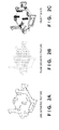
- Figs. 2A and 2B are views showing an example of a three-dimensional shape model
- Fig. 2C shows a polygon model which expresses a shape of an object.
- a three-dimensional shape model is configured by three-dimensional plane information (to be referred to as plane geometric features hereinafter) and three-dimensional line segment information (to be referred to as line geometric features hereinafter).
- plane geometric features are local three-dimensional plane information on an object surface, which includes three-dimensional positions and a three-dimensional normal direction
- each line geometric feature is local three-dimensional line segment information on an object contour, which includes three-dimensional positions and a three-dimensional line segment direction.
- data obtained by capturing an image of a target object may be used in addition to a CAD model.
- geometric features generally indicates both plane and line geometric features.
- a plane geometric feature is used to measure corresponding distances between three-dimensional coordinates of the plane geometric feature and a distance point group on a range image.
- a line geometric feature is used to measure corresponding distances between projected coordinates of the line geometric feature and an edge on a grayscale image.
- a three-dimensional shape model is saved in the three-dimensional shape model input unit 110, and is input to the geometric feature grouping unit 140.
- the position and orientation setting unit 120 sets a plurality of different viewing conditions for a three-dimensional shape model.
- a position and orientation of a virtual image sensing device used to view a three-dimensional shape model is generated exhaustively as viewing conditions to discretely view the model from various directions.
- a practical processing method of position and orientation settings of an image sensing device will be described later.
- an image sensing device which is virtually disposed will be referred to as a virtual image sensing device hereinafter.
- the position and orientation selection unit 130 selects one of a plurality of viewing conditions for the three-dimensional shape model set by the position and orientation setting unit 120. Note that in this embodiment, the position and orientation selection unit 130 selects one set of positions and orientations of a plurality of virtual image sensing devices for the three-dimensional shape model. Practical processing will be described later.
- the geometric feature grouping unit 140 groups geometric features based on similarities of Jacobians of the geometric features for each viewing condition selected by the position and orientation selection unit 130 of the plurality of viewing conditions set by the position and orientation setting unit 120.
- the geometric feature grouping unit 140 executes clustering based on similarities of influences of geometric features on the position and orientation parameters as grouping. Details of practical processing will be described later.
- the viewpoint-dependent model saving unit 150 saves geometric feature information grouped by the geometric feature grouping unit 140 together with the viewing condition at that time (relative position and orientation information between the three-dimensional shape model used for grouping and virtual image sensing device) as a viewpoint-dependent position and orientation estimation model.
- a position and orientation estimation model is generated by combining viewpoint-dependent position and orientation estimation models of all the viewing conditions set by the position and orientation setting unit 120 into one.
- a two-dimensional image sensing device 20 is a camera used to capture a normal two-dimensional image.
- a two-dimensional image to be captured may be either a grayscale image or color image.
- the two-dimensional image sensing device 20 captures and outputs a grayscale image.
- Intrinsic parameters such as a focal length, principal point position, lens distortion parameters, and the like of the camera may be acquired by referring to the specifications of a device to be used. Alternatively, such parameters may be acquired by executing calibration in advance by a method disclosed in [ R.Y. Tsai, "A versatile camera calibration technique for high-accuracy 3D machine vision metrology using off-the-shelf cameras and lenses," IEEE Journal of Robotics and Automation, vol. RA-3, no. 4, 1987 .].
- a range image sensing device 30 measures three-dimensional information of points on an object surface as a measurement target.
- a range sensor which outputs a range image is used.
- the range image is an image in which each pixel has depth information.
- the range sensor a one-shot active type sensor, which irradiates a target with multi-slit lines assigned color IDs of different wavelengths, captures reflected light using a camera, and makes distance measurements by triangulation, is used.
- the range sensor is not limited to this, for example, as an alternative, a Time-of-flight type sensor using a flight time of light may be used.
- a passive type sensor which calculates depths of respective pixels by triangulation from an image captured by a stereo camera, may be used.
- any other sensors may be used as long as they measure a range image, such that the gist of the present invention will not be lost.
- a range image measured by the range image sensing device 30 is input to the information processing apparatus 1 via the image input unit 160. Also, assume that optical axes of the range image sensing device 30 and two-dimensional image sensing device 20 are matched, and the correspondence relationship between respective pixels of a grayscale image output by the two-dimensional image sensing device 20 and those of a range image output by the range image sensing device 30 is given.
- the application of the present invention is not limited to a case in which a grayscale image and range image have the same viewpoint.
- an image sensing device used to capture a grayscale image and that used to capture a range image are located at different positions and orientations, and a grayscale image and range image may be captured from different viewpoints.
- the relative position and orientation between the image sensing devices is given, and the grayscale image and range image are associated with each other by projecting a three-dimensional point group in the range image onto the grayscale image.
- the positional relationship between the image sensing devices is not particularly limited as long as a relative position and orientation between the image sensing devices used to capture images of an identical object is given, and the correspondence relationship between these images can be calculated.
- the image input unit 160 inputs a two-dimensional image captured by the two-dimensional image sensing device 20 and a range image captured by the range image sensing device 30 to the information processing apparatus 1.
- the image input unit 160 is implemented by an analog video capture board when outputs of the image sensing devices are analog outputs such as NTSC outputs.
- the image input unit 160 is implemented by, for example, an IEEE1394 interface board if the outputs of the image sensing devices are digital outputs such as IEEE1394 outputs.
- the image input unit 160 may acquire images by reading out digital data of a still image or moving image, which is stored in advance in a storage device (not shown).
- the geometric feature selection unit 170 selects geometric features used to calculate a position and orientation from those which are grouped by the geometric feature grouping unit 140 and are saved in the viewpoint-dependent model saving unit 150. Practical processing will be described later.
- the position and orientation estimation unit 180 calculates associations with geometric features selected by the geometric feature selection unit 170 based on a grayscale image and range image captured by the two-dimensional image sensing device 20 and range image sensing device 30. Then, a position and orientation of a target object is calculated. Details of practical processing will be described later.
- the example of the arrangement of the information processing apparatus 1 incorporates a computer.
- the computer includes a main control unit such as a CPU, a ROM (Read Only Memory), a RAM (Random Access Memory), and a storage unit such as an HDD (Hard Disk Drive).
- a main control unit such as a CPU, a ROM (Read Only Memory), a RAM (Random Access Memory), and a storage unit such as an HDD (Hard Disk Drive).
- an input/output unit such as buttons, a display, or a touch panel, a communication unit such as a network card, and the like may be connected. Note that these components are connected via, for example, a bus, and are controlled when the main control unit executes programs stored in the storage unit.
- FIG. 3 is a flowchart showing the processing sequence of the position and orientation estimation model generation method according to this embodiment.
- step S1000 the three-dimensional shape model input unit 110 inputs a three-dimensional shape model of a target object.
- step S1100 the position and orientation setting unit 120 sets viewing conditions of the three-dimensional shape model of the target object.
- the viewing conditions position and orientation settings of a virtual image sensing device used to view the three-dimensional shape model are made.
- a geodesic sphere which encloses an object, as shown in Fig. 4 . More specifically, a reference position and orientation is set to have each vertex of the geodesic sphere as a position of a virtual image sensing device 501, and each viewing direction of a three-dimensional shape model 502 from there as a viewpoint of the virtual image sensing device 501.
- An image to be obtained when an image of the three-dimensional shape model is captured from the set position and orientation is an image obtained by mapping the three-dimensional shape model onto a plane corresponding to an image sensing plane of the virtual image sensing device.
- an arbitrary value may be set. Note that a radius of a sphere approximated by a geodesic sphere corresponds to a distance between the virtual image sensing device 501 and the three-dimensional shape model 502 of the target object.
- an image sensing distance is assumed in advance in association with an image used in the position and orientation estimation, that distance is desirably set to be equal to the radius of the geodesic sphere.
- geodesic spheres whose sizes are different may be prepared at each step, and vertices of the respective geodesic spheres may be set as reference positions and orientations.
- the reference position and orientation setting method is not limited to this.
- a sphere which encloses the three-dimensional shape model of the target object may be assumed, latitudes and longitudes are assigned to that sphere like a globe, and viewpoints may be assured at equal intervals in the latitude and longitude directions.
- any other methods may be used as long as they can simulate relative positions and orientations between the virtual image sensing device and object in the actual position and orientation estimation.
- step S1200 the position and orientation selection unit 130 selects a position and orientation from a plurality of position and orientation conditions set in step S1100. More specifically, a position and orientation to be processed is selected and is set as a viewpoint of the virtual image sensing device used to view the three-dimensional shape model.
- the geometric feature grouping unit 140 calculates Jacobians of geometric features using the position and orientation of the virtual image sensing device set in step S1200 so as to calculate similarities of influences on position and orientation parameters between geometric features.
- a Jacobian of a geometric feature is a value which indicates a degree of a change in corresponding distance between a geometric feature of interest and image feature when parameters of six degrees of freedom of the position and orientation of the image sensing device change by a small amount.
- a Jacobian is a distance between a point and line on an image.
- a Jacobian is a matrix including primary partial differential coefficients associated with respective elements of a position and orientation as elements when distances between points and a plane on a three-dimensional space are defined as functions of a position and orientation.
- a parameter of the six degrees of freedom of the position and orientation, on which that geometric feature readily influences can be recognized. Note that this embodiment uses a Jacobian.
- the present invention is not limited to this, and indices which represent influences of geometric features on position and orientation parameters may be used. Derivation methods of Jacobians of plane and line geometric features will be described in detail below.
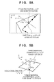
- Fig. 5A is a view for explaining calculations of a line-point distance between a line geometric feature and an image feature on a grayscale image.
- (u, v) be a position at which a line geometric feature is projected onto an image based on a position and orientation s of the virtual image sensing device
- (n u , n v ) (unit vector) be a normal direction to that position
- (u', v') be coordinates of the image feature corresponding to the line geometric feature.
- degrees of freedom of the position and orientation s of the virtual image sensing device are six degrees of freedom. That is, s is a six-dimensional vector, which includes three elements s1, s2, and s3 that express a position of a measurement target object, and three elements s4, s5, and s6 that express an orientation.
- the three elements that express the orientation are expressed using Euler angles, by a three-dimensional vector in which directions express rotation axes passing through an origin and a norm expresses a rotation angle, or the like.
- J 2 ⁇ D ⁇ err 2 ⁇ D ⁇ s 1 ⁇ err 2 ⁇ D ⁇ s 2 ⁇ err 2 ⁇ D ⁇ s 3 ⁇ err 2 ⁇ D ⁇ s 4 ⁇ err 2 ⁇ D ⁇ s 5 ⁇ err 2 ⁇ D ⁇ s 6
- Fig. 5B is a view for explaining a plane-point distance between a plane geometric feature and a corresponding point (three-dimensional point in a range image).
- step S1300 Upon completion of calculations of the aforementioned Jacobians for all line and plane features, the process of step S1300 ends, and the process advances to step S1400.
- step S1400 the geometric feature grouping unit 140 groups features having similar influences on estimation of the six degrees of freedom of the position and orientation based on the Jacobians of the line and plane geometric features calculated in step S1300.
- geometric features are grouped by executing, for example, hierarchical clustering using the well known Ward method based on the similarities of the Jacobians. Note that since the Jacobians of the line geometric features and those of the plane geometric features have different scales of inter-correspondence distances to be measured, they are distinguished from each other, and are independently grouped.
- step S1400 Practical processing of grouping of the line and plane geometric features in step S1400 will be described in detail below with reference to the flowchart shown in Fig. 6 .
- step S1410 as an initial cluster, a cluster group including only one geometric feature is generated. That is, when the total number of geometric features is N, N clusters are generated. The generated clusters are saved as those of a lowermost layer.
- step S1420 After completion of calculations of the non-similarities ⁇ S AB between the clusters for all the combinations between the clusters, the process of step S1420 ends, and the process advances to step S1430.
- step S1420 clusters of a combination having the lowest non-similarity ⁇ S AB are merged to form one cluster. Then, the merged cluster is saved as that of a layer upper by one than the clusters before merging.
- step S1430 If the total number of clusters is 1 as result of step S1430, the processing ends; otherwise, the process returns to step S1420 to repeat the processing until the total number of clusters becomes 1.
- geometric features can be grouped into a dendritic classification structure called a dendrogram.
- a dendrogram When the dendrogram is cut at a position close to a distal end of a branch (lower layer), a large number of clusters each including a small number of elements are obtained; when it is cut at a position close to a stool of a branch (upper layer), a small number of clusters each including a large number of elements are obtained.
- clusters included in the dendrogram have a hierarchical structure, that is, small classification - middle classification - large classification, when they are cut at an arbitrary layer, an arbitrary number of clusters can be obtained.
- step S1400 Upon completion of grouping of all the plane geometric features and that of all the line geometric features, the process of step S1400 ends, and the process advances to step S1500.
- step S1500 the viewpoint-dependent model saving unit 150 saves a set of the grouping result of the geometric features obtained in step S1400 and the position and orientation of the virtual image sensing device selected in step S1200 as a viewpoint-dependent position and orientation estimation model.
- the model generation apparatus 2 determines in step S1600 whether or not the processes from step S1200 to step S1500 have been executed for all the positions and orientations of the virtual image sensing device generated in step S1100. If positions and orientations to be processed still remain, the process returns to step S1200 to repeat the processing for the next position and orientation.
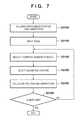
- Fig. 7 is a flowchart showing the position and orientation estimation processing. Note that the position and orientation estimation processing may be executed by an external apparatus by transferring the processing result of Fig. 3 to the external apparatus.
- step S2000 the information processing apparatus 1 inputs approximate values of a position and orientation of an object with respect to the image sensing device including the two-dimensional image sensing device 20 and range image sensing device 30.
- the information processing apparatus 1 uses previous measurement values (at the previous time) as approximate position and orientation under the assumption that it continuously executes the position and orientation measurements in the time-axis direction.
- an input method of the approximate values of the position and orientation is not limited to this.
- a velocity or angular velocity of an object may be estimated using a time-series filter based on previous measurement values of the position and orientation to estimate a current position and orientation based on the previous position and orientation and the estimated velocity or acceleration.
- images of a target object which are captured at various orientations, may be held as templates, and template matching may be applied to an input image to estimate an approximate position and orientation of the target object.
- a sensor can measure a position and orientation of an object
- output values of the sensor may be used as approximate values of the position and orientation.
- the sensor may be, for example, a magnetic sensor, which measures a position and orientation by detecting a magnetic field generated by a transmitter using a receiver attached to an object.
- the sensor may be an optical sensor, which measures a position and orientation by capturing an image of markers arranged on an object using a camera fixed to a scene.
- any other sensors may be used as long as they can measure a position and orientation of six degrees of freedom.
- these values are used as approximate values.
- step S2100 the image input unit 160 inputs a grayscale image and range image.
- the image input unit 160 acquires a grayscale image from the two-dimensional image sensing device 20 first.
- the image input unit 160 acquires a range image from the range image sensing device 30.
- a range image stores distances from the image sensing device to the surface of a measurement target object.
- the optical axes of the two-dimensional image sensing device 20 and range image sensing device 30 are matched, the correspondence relationship between respective pixels of a grayscale image and those of a range image is given.
- step S2200 the position and orientation estimation unit 180 selects one viewpoint-dependent position and orientation estimation model from the position and orientation estimation models, thus obtaining geometric features grouped as the hierarchical structure in step S1400.
- the position and orientation estimation unit 180 selects a viewpoint-dependent position and orientation estimation model corresponding to a position and orientation most similar to the approximate position and orientation input in step S2000 from a plurality of viewpoint-dependent position and orientation estimation models saved as the position and orientation estimation models.
- orientation differences ⁇ R between the approximate position and orientation and those of the virtual image sensing device are calculated for a plurality of reference positions and orientations, and the model having the smallest difference value is selected.
- a position difference ⁇ T and orientation difference ⁇ R between the approximate position and orientation and reference position and orientation may be respectively calculated, positions and orientations of all the virtual image sensing devices may be respectively ranked in association with the values ⁇ T and ⁇ R, and the model having the smallest sum of the ranks may be selected.
- the selection method of the position and orientation estimation model is not limited to the aforementioned methods, and any other methods may be used as long as calculations are made based on the similarities between the approximate position and orientation and those of the virtual image sensing devices. That is, the selection method is not particularly limited.
- step S2300 the geometric feature selection unit 170 selects geometric features used in position and orientation calculations from those grouped as the hierarchical structure in the viewpoint-dependent mode saving unit 150.
- six clusters are extracted from geometric features grouped as the hierarchical structure. By randomly selecting one geometric feature from those of each extracted cluster, a total of six geometric features for position and orientation estimation are selected. By selecting geometric features from different clusters, those which do not have similar influences on the position and orientation parameters can be selected.
- the number of clusters to be extracted from the hierarchical structure and the number of geometric features to be used are not particularly limited except that at least six geometric features are typically required (since known position and orientation parameters have six respective degrees of freedom) so as to estimate a position and orientation.
- no problem is particularly posed when three clusters may be extracted, and two geometric features may be randomly selected from each cluster.
- a new setting unit used to set the number of clusters to be extracted and the number of geometric features to be selected may be added, and the numbers of clusters and geometric features may be arbitrarily set to execute estimation processing without losing the technical effect of the present embodiment.
- the number of geometric features to be selected can be six in the sense of a minimum required number. Also, the number of clusters to be extracted may be the same as the number of geometric features to be selected since it is desirable to select non-similar geometric features.
- step S2400 associations between the grayscale image and range image input in step S2100 and the line and plane geometric features selected in step S2300 are calculated, and a position and orientation of the measurement target object is estimated based on the association result.
- the position and orientation estimation processing to be executed by the position and orientation estimation unit 180 will be described in detail below.
- a three-dimensional point group in the range image input in step S2100 are associated with the plane geometric features.
- all the plane geometric features selected in step S2300 are projected onto the range image.
- distance point groups on the range image corresponding to respective projected planes are held as three-dimensional points corresponding to the respective plane geometric features.
- edges on the grayscale image input in step S2100 are associated with the line geometric features.
- all the line geometric features selected in step S2300 are projected onto the image, thereby associating edges detected on the image with the line geometric features.
- a closest edge on the image is associated with the projected line geometric feature.
- the position and orientation estimation method based on the maximum likelihood estimation is not related to the gist of the present invention, and a description of detailed processing will not be given. Further details would be known the person skilled in the art from, for example, the aforementioned literature. Note that the position and orientation calculation method of the measurement target object is not limited to the aforementioned method. For example, iterative calculations based on the Levenberg-Marquardt method may be executed, or the steepest descent method may be used. Alternatively, other nonlinear optimization calculation methods such as a conjugate gradient method and ICCG method may be used.
- step S2400 It is determined in step S2400 whether or not the position and orientation updated in step S2400 have converged (that is, whether or not iterative calculations are required). It is determined that the position and orientation have converged when correction values are nearly zero or when a difference between square sums of error vectors before and after correction is nearly zero.
- step S2200 the processing is executed from selection of a viewpoint-dependent position and orientation estimation model using the updated position and orientation. Note that when updated amounts of the position and orientation updated in step S2400 are small, the process may return to step S2400 to execute the position and orientation update processing using the same geometric features. If it is determined that the position and orientation has converged, this processing ends, and final estimated values of a relative position and orientation between the image sensing device and target object are decided.
- geometric feature groups having similar influences on estimation parameters of the six degrees of the position and orientation are grouped in advance, geometric features effective for estimation can be quickly selected in the position and orientation estimation processing.
- the position and orientation estimation can be efficiently executed based on a small number of geometric features without disproportionately using geometric features having similar influences on the position and orientation parameters.
- the aforementioned embodiment has explained the method based on hierarchical clustering using the Ward method as the geometric feature grouping method.
- the geometric feature grouping method is not limited to this.
- similarity calculation methods such as a nearest neighbor method, farthest neighbor method, group average method, centroid method, median method, and flexible method other than the Ward method may be used in similarity calculations.
- a non-hierarchical clustering method represented by k-means may be used.
- grouping processing can be executed as follows.
- respective sample points i are classified into C j groups having a minimum distance
- an average value of Jacobians of sample points which belong to each group is calculated, and the reference C j of that group is updated by the calculated average value.
- classification and updating are iterated until C j need not be updated, thereby grouping geometric features.
- the total number M of groups may be set in the same manner as the number of clusters to be extracted in step S2300 in the aforementioned embodiment, for example, the number of geometric features to be selected.
- the total number M of groups may be set to be six. Note that the decision method and condition associated with the settings of the total number M of groups are the same as those of the settings of the number of clusters to be extracted in step S2300.
- geometric features having similar Jacobians of the geometric features are grouped.
- the criterion used upon grouping geometric features is not limited to this.
- geometric features having non-similar Jacobians may be grouped into one group. More specifically, grouping may be made by selecting clusters having a largest non-similarity ⁇ S AB between clusters calculated in step S1420.
- geometric features corresponding to non-similar Jacobians are grouped into one group, geometric features corresponding to non-similar Jacobians are selected by randomly selecting geometric features from one cluster in step S2300.
- the criterion upon grouping is not limited to the grouping method of grouping geometric features corresponding to similar Jacobians, and those corresponding to non-similar Jacobians may be clustered.
- the criterion is not particularly limited as long as the grouping criterion matches that upon selection of geometric features from the grouping result at the time of the position and orientation estimation, and any other criteria may be used in grouping, thus posing no problem.
- a plurality of geometric feature sets may be prepared in a Random Access Consensus (RANSAC) manner, and a most proper geometric feature set may be discriminated by iterating the position and orientation calculations and evaluation of the result using each of the geometric feature sets, thereby executing processing for calculating a position and orientation.
- RANSAC Random Access Consensus
- step S2300 by iterating random selection of one geometric feature from those of respective clusters extracted from the hierarchical structure a plurality of times, a plurality of position and orientation calculation geometric feature sets each including six geometric features are prepared.
- step S2400 positions and orientations are respectively estimated for respective geometric feature sets selected in step S2300. Then, geometric features are projected onto an image again based on the estimated positions and orientations, and a position and orientation corresponding to the smallest sum total of inter-correspondence distances between geometric features and image features is selected as a most proper position and orientation.
- the selection method of geometric features used in the position and orientation estimation, and the position and orientation estimation method using the selected geometric features are not limited to those of the aforementioned embodiment, and any other methods may be used as long as a position and orientation can be estimated based on selected geometric features.
- the six degrees of freedom of the position and orientation of the measurement target object are calculated based on the association result between the geometric features an image.
- the position and orientation estimation method is not limited to the method of estimating all the six degrees of freedom of the position and orientation.
- geometric features having similar influences on the six-degrees-of-freedom parameters of the position and orientation may be selected, and some of the six-degrees-of-freedom parameters of the position and orientation may be selected based on them.
- step S2300 a plurality of (for example, six) geometric features are selected from those in a single cluster extracted from the hierarchical structure, thereby selecting geometric features having similar influences on the six-degrees-of-freedom parameters of the position and orientation.
- step S2400 based on the association result between the selected geometric features and image, only position and orientation parameters to which the selected geometric features readily contribute are estimated. For example, when geometric features which readily contribute to an image plane X direction are selected, parameters to be estimated are limited to the image plane X direction. Since the method itself of estimating only some of position and orientation parameters is not essential to the gist of the present invention, a description of detailed processing will not be given.
- the position and orientation estimation method of the present invention is not limited to the method of estimating all the six-degrees-of-freedom parameters of the position and orientation.
- Information to be estimated, and the position and orientation estimation method are not particularly limited as long as information of a position and/or orientation can be estimated based on selected geometric features, and any other methods can be used.
- the aforementioned embodiment has explained the method based on the nonlinear least square method as the position and orientation estimation method based on the association result between the image and geometric features.
- the position and orientation estimation method to be applied to the information processing apparatus of the present invention is not limited to this.
- the present invention is applicable to a case in which a position and orientation is estimated using a time-series filter such as an extended Kalman filter based on the association result between the geometric features and image.
- a position and orientation is estimated based on the time-series filter, it is possible to estimate a position and orientation from one geometric feature.
- the position and orientation estimation based on one geometric feature estimates only parameters to which that geometric feature readily contribute of the six-degrees-of-freedom parameters of the position and orientation. For this reason, when only geometric features which readily contribute to estimation and correspond to similar degrees of freedom are selected, it is impossible to estimate all the six degrees of freedom of the position and orientation.
- step S2300 a geometric feature used to update a position and orientation is selected.
- six geometric features used in the position and orientation calculations are selected.
- at least one piece of information need only be selected to allow estimation. For this reason, in this modification, in the process of step S2300, one geometric feature is randomly selected.
- step S2400 a position and orientation is updated by filtering processing based on the extended Kalman filter on the basis of the association result between the selected geometric feature and image. Since the calculation method itself of the extended Kalman filter based on the selected one geometric feature and associated data is not related to the gist of the present invention, a detailed description thereof will not be given. The skilled person would be aware of for example Y. Hel-Or, M. Werman, "Pose estimation by fusing noisy data of different dimensions," IEEE Transactions on Pattern Analysis and Machine Intelligence, vol. 17, no. 2, pp. 195 - 201, 1995 . and thus a detailed description of the processing is not necessary.
- step S2500 Upon completion of the position and orientation updating processing based on one geometric feature amount, whether or not to iterate the position and orientation updating processing is determined in step S2500.
- a limit of a processing time to be spent for the position and orientation processing is decided in advance, and the updating processing is iterated until the limit is reached.
- the current position and orientation is decided as the final position and orientation, thus ending the processing of the information processing apparatus 1.
- the process returns to step S2300, and a new geometric feature is selected. At this time, since that geometric feature is not selected from a cluster to which the previously selected geometric feature belongs, a geometric feature having a non-similar influence on the position and orientation estimation can be selected.
- the position and orientation estimation method using geometric feature groups is not limited to the aforementioned embodiment.
- the position and orientation estimation method is not particularly limited as long as a position and orientation can be estimated using geometric features selected from geometric feature clusters, and any other methods may be used.
- the nonlinear least square method and the method based on the time-series filter have been described as the position and orientation estimation method based on the association result between the image and geometric features.
- the position and orientation estimation method to be applied to the information processing apparatus of the present invention is not limited to these methods.
- the present invention is applicable to a case in which a position and orientation is calculated by matching based on the association result between the geometric features and image.
- step S2400 a large number of positions and orientations are generated as a position and orientation of the target object so as to exhaustively cover values of the six degrees of freedom within predetermined ranges to have the approximate position and orientation as the centers.
- a position and orientation of the target object is estimated. More specifically, as settings of positions and orientations to be searched, values of all combinations of the six degrees of freedom of the position and orientation are set to have the input approximate position and orientation values as the centers. At this time, settings of a maximum width and step width of a position to be exhaustively set and those of an orientation to be exhaustively set are not particularly limited.
- the positions and orientations to be searched are set by setting the maximum width of a position to be equal to the size of the target object, that of an orientation to be 90°, the step width of a position to be 1 mm, and that of an orientation to be 1°. Then, one set of the set position and orientation is selected, and a three-dimensional point group in the range image, edges on the grayscale image, and the selected geometric features are associated with each other based on the selected position and orientation.
- the position and orientation estimation method based on the selected geometric features is not limited to the least square method and the method based on the time-series filter.
- the position and orientation calculation method is not particularly limited as long as a position and orientation corresponding to the selected geometric features which apply to the grayscale and range image can be estimated, and any other methods may be used.
- the information processing apparatus of the present invention is not limited to the case in which both the grayscale and range images are captured.
- the information processing apparatus of the present invention is applicable to a case in which only the range image is captured.
- An information processing apparatus of this modification has an arrangement in which the two-dimensional image sensing device 20 is removed from that shown in Fig. 1 .
- the position and orientation estimation processing is the same as that of the aforementioned embodiment, except that the grayscale image input processing in step S2100 is omitted, and the association processing between the grayscale image and geometric features in step S2400 is omitted.
- the information processing apparatus of the present invention is applicable to a case in which only the grayscale image is captured.
- the information processing apparatus of this modification has an arrangement in which the range image sensing device 30 is removed from that shown in Fig. 1 , and the position and orientation estimation processing is the same as that of the aforementioned embodiment, except that the range image input processing in step S2100 is omitted, and the association processing between the range image and geometric features in step S2400 is omitted.
- the aforementioned embodiment has explained the grouping method based on Jacobians of geometric features as that of geometric features having similar influences on the position and orientation parameters in the geometric feature grouping unit 140.
- the geometric feature grouping method is not limited to the method according to similarities of Jacobians. For example of geometric features set on lines or planes of the three-dimensional shape model, those corresponding to similar angles or positions of the lines or planes are determined to have similar influences on the position and orientation parameters. Then, geometric features corresponding to similar angles or positions of the lines or planes may be grouped into a single group.
- the information processing apparatus 1 is not limited to the case in which both the grayscale and range images are obtained, and is applicable without any problem as long as either one image is obtained.
- a position and orientation of an object 60 to be measured is estimated based on a two-dimensional image and range image obtained by a two-dimensional image sensing device 20 and range image sensing device 30, and an industrial robot arm (robot 50) is controlled to grip that object based on the estimated position and orientation.
- an application example of the information processing apparatus 1 according to another embodiment of the present invention will be described below with reference to Fig. 8.
- Fig. 8 shows an arrangement example of a robot system in which the object 60 to be measured is gripped using the information processing apparatus 1 and robot 50.
- the robot 50 is controlled by a robot controller 40 to move its hand to an instructed position so as to grip an object. Since the position of the object 60 to be measured on a work table is changed, the current position and orientation of the object 60 to be measured has to be estimated to execute gripping control of the robot.
- the two-dimensional image sensing device 20 is a camera used to capture a normal two-dimensional image and the range image sensing device 30 is a range sensor used to measure distances to an object surface. These image sensing devices are arranged at a position of the hand of the industrial robot arm, where they capture images of the object 60 to be measured.
- the information processing apparatus 1 estimates the position and orientation of the object 60 to be measured based on a two-dimensional image and range image obtained from the two-dimensional image sensing device 20 and range image sensing device 30.
- the position and orientation of the object 60 to be measured which is estimated by the information processing apparatus 1, is input to the robot controller 40, thereby controlling the robot to, for example, grip the object 60 to be measured. Since an information processing apparatus of the present invention estimates the position and orientation of the object 60 to be measured, the robot system can grip the object 60 to be measured even when the position of the object 60 to be measured is indeterminate.
- the present invention can adopt, for example, embodiment in the form of a system, apparatus, method, program, storage medium, or the like. More specifically, the present invention may be applied to either a system including a plurality of devices or an apparatus consisting of a single device.
- the present invention includes a case in which the functions of the aforementioned embodiments are achieved when a software program is directly or remotely supplied to a system or apparatus, and a computer of that system or apparatus reads out and executes the supplied program code.
- the supplied program is a computer program corresponding to the flowchart shown in the drawing in the embodiments.
- the program code itself installed in the computer implements the present invention. That is, the present invention includes the computer program itself required to implement the functional processing of the present invention.
- the form of the program may be an object code, a program executed by an interpreter, or script data to be supplied to an OS as long as they have functions of the program.
- a computer-readable storage medium required to supply the computer program includes, for example, a floppy® disk, hard disk, optical disk, magnetooptical disk, MO, CD-ROM, CD-R, CD-RW, magnetic tape, nonvolatile memory card, ROM, DVD (DVD-ROM, DVD-R), and the like.
- a connection may be established to a homepage on the Internet using a browser of a client computer, and the computer program of the present invention may be downloaded from the homepage to a recording medium such as a hard disk.
- the program to be downloaded may be a compressed file including an automatic installation function.
- Program codes included in the program of embodiments of the present invention are divided into a plurality of files, and the respective files may be downloaded from different homepages, thus implementing embodiments of the present invention. That is, a WWW server which allows a plurality of users to download the program file required to implement the functional processing by computers is included in embodiments of the present invention.
- the encrypted program in embodiments of the present invention may be stored in a storage medium such as a CD-ROM, which may be delivered to users.
- a storage medium such as a CD-ROM
- the user who has cleared a predetermined condition is allowed to download key information required to decrypt the encrypted program from a homepage via the Internet, and to execute the program decrypted using the key information, thus installing the program in a computer.
- the functions of the aforementioned embodiments can be implemented when a computer executes the readout program.
- the functions of the embodiments may be implemented in cooperation with an OS or the like, which is running on the computer, based on instructions of that program.
- the OS or the like executes some or all of actual processes, thereby implementing the functions of the aforementioned embodiments.
- the program read out from the recording medium may be written in a memory included in a function expansion board inserted in a computer or a function expansion unit connected to the computer, thus implementing some or all of the functions of the aforementioned embodiments.
- a CPU or the like included in that function expansion board or unit executes some or all of actual processes based on instruction of that program.
- image features to be used are decided using a reference image whose position and orientation is given (a captured image obtained by capturing an image of a viewing target object in a previous frame or a model image set with texture data). Then, using such image features, a position and orientation of an image sensing device associated with a current frame is calculated, thus improving stability of the position and orientation estimation. That is, according to the embodiments, when three-dimensional line segment models extracted from three-dimensional model data of a viewing target object are considerably different from features which can be extracted from the viewing target object in the captured image, the position and orientation can be stably estimated. Using features based on surface colors of the viewing target object in addition to geometric features extracted from a three-dimensional model, the position and orientation can be estimated using information which is not included in the three-dimensional model data.
- This embodiment estimates a position and orientation of an object to be measured as a position and orientation estimation target by model fitting using a three-dimensional shape model having the same shape as the object to be measured.
- association processing of this embodiment the following processing is executed first. That is, positions, on a captured image, of geometric features (sample points set on linen segments and planes of a three-dimensional shape model in this embodiment) of the three-dimensional shape model are calculated based on approximate values of a position and orientation (position and orientation approximate values) of an object to be measured with respect an image sensing device used to capture an image of the object to be measured. Next, points corresponding to the sample points (corresponding points) are searched for from the captured image, and distances between the sample points and corresponding points (inter-correspondence distances) are calculated. Assume that this captured image includes a grayscale image and range image in this embodiment.
- outliers mixed in the association result are precisely removed.
- sample points are classified so that sample points for which similar inter-correspondence distances are predicted belong to identical groups. Then, after the corresponding points corresponding to the sample points are searched for, the search results (association results) are determined for respective groups.
- a component 5102 appears in an image.
- a three-dimensional shape model which is projected onto the image based on position and orientation approximate values of the component 5102, is displayed to be superimposed on the component 5102.
- the shape model in Fig. 9 is displayed for the sake of descriptive convenience.
- the shape model is not projected onto the image in practice, and positions of sample points on the image are calculated.
- points corresponding to sample points 5103 on a three-dimensional shape model 5101 are searched for to detect corresponding points.
- points 5104 on sides of the component 5102 are searched for.
- lengths of line segments which connect the sample points 5103 and points 5104, are calculated as inter-correspondence distances 5105.
- Fig. 9 shows points 5106 and 5107, which are erroneously associated as corresponding points, as outliers. Since inter-correspondence distances of all sample points are statistically used to determine outliers, it is easily to determine a correspondence having a largely different inter-correspondence distance from other sample points like the point 5106. However, it is difficult to determine a correspondence having an inter-correspondence distance closer to a statistically standard inter-correspondence distance like the point 5107.
- sample points are grouped, and outliers are determined for respective groups. Grouping is executed so that sample points, which are expected to have similar inter-correspondence distances are classified into an identical group. For example, adjacent sample points on a single line segment are classified into a single group like a group 5201. As can be seen from Fig. 10 , correctly associated sample points are expected to have similar inter-correspondence distances in a single group. Therefore, when outlier determination is executed for each group, even an outlier having a small deviation like the point 5107 can be determined with high reliability.
- an image sensing device 5310 is connected to an information processing apparatus 5300.
- the image sensing device 5310 will be described first.
- the image sensing device 5310 has a camera function required to capture a two-dimensional image of a scene, and a range sensor required to acquire a range image. In this embodiment, assume that the image sensing device 5310 captures an image of an object to be measured.
- the two-dimensional image may be either a grayscale image or color image.
- Intrinsic parameters such as a focal length and principal point position of a camera used to capture an image, and lens distortion parameters are calibrated in advance by a method described in the following literature: R.Y. Tsai, "A versatile camera calibration technique for high-accuracy 3D machine vision metrology using off-the-shelf cameras and lenses," IEEE Journal of Robotics and Automation, vol. RA-3, no. 4, 1987 .
- the range sensor an active type sensor which captures reflected light of a laser beam, with which a target (an object to be measured in this case) is irradiated, and measures distances by triangulation is used.
- the range sensor is not limited to this, and any other sensors may be used as long as they measure a range image.
- a relative position and orientation between the camera and range sensor is fixed, and is calibrated in advance.
- the following calibration method can be used. That is, in this method, a calibration object, a three-dimensional shape of which is given, is viewed from various directions, and a relative position and orientation is calculated from differences between the position and orientation of the calibration object based on the two-dimensional image and that of the calibration object based on the range image.
- the two-dimensional image and range image obtained by the image sensing device 5310 are input to the information processing apparatus 5300.
- these two-dimensional image and range image may be captured in advance, and may be stored in an arbitrary storage device.
- the two-dimensional image and range image are input from this storage device to the information processing apparatus 5300. That is, the acquisition method of the two-dimensional image and range image by the information processing apparatus 5300 is not limited to a specific method.
- position and orientation approximate values of an object to be measured with respect to the device which captures the two-dimensional image and range image are input from a position and orientation approximate value input unit 5303 (to be described later).
- the position and orientation approximate values are also those of a viewpoint with respect to an object to be measured with reference to the object to be measured.
- the information processing apparatus 5300 will be described below.
- the two-dimensional image and range image output from the image sensing device 5310 are input to an association unit 5305 via an image input unit 5301.
- a shape model holding unit 5302 holds three-dimensional shape model information (model information) of the same shape as that of an object to be measured, and position information of respective sample points set in advance on the three-dimensional shape model.
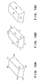
- a three-dimensional shape model to be expressed by the model information includes, for example, that based on three-dimensional CAD data. More specifically, three-dimensional shape model includes a CAD model itself which can be handled by three-dimensional CAD software or a model including a plurality of polygon elements, which are used in used in the computer graphics field, and are obtained by converting a three-dimensional CAD Mode. The following description will be given under the assumption that the three-dimensional model is a model including a plurality of polygons. A configuration example of the model information used in this embodiment will be described below with reference to Figs. 12A to 12F .
- the three-dimensional model includes elements such as points, lines (sides), and planes, as shown in Figs. 12A to 12F .
- Figs. 12A to 12C show the same three-dimensional shape model.
- Figs. 12A to 12C show vertices, sides, and planes when viewed from a certain viewpoint, and do not show those which cannot be viewed from this viewpoint.
- model information of such three-dimensional shape model includes indices and coordinate values of respective vertices, indices of respective sides and those of vertices of two ends of each of these sides, indices of respective planes, those of sides of each of these planes, and normal vector components.
- the coordinate value of each vertex may be set with reference to a local origin of the three-dimensional shape model, or a point to be used as a reference point is not particularly limited. The same applies to position information of each sample point to be described below.
- Sample points include points (line sample points) set on sides of the three-dimensional shape model so as to be associated with edge features of a grayscale image, and points (plane sample points) set on planes of the three-dimensional shape model so as to be associated with three-dimensional points in a range image.
- sample points can be used in association processing depending on the ways lines and planes on an image of the three-dimensional shape mode are viewed.
- vertices P1 to P4 and P6 to P8 are viewable, but a vertex P5 is not viewable.
- sides L1 to L7, L10, and L11 are viewable, but sides L8, L9, and L12 are not viewable.
- planes S1, S3, and S4 are viewable, but planes S2, S5, and S6 are not viewable.
- sides and planes, which are viewable on the three-dimensional shape model from a plurality of viewpoints set on respective vertices of a geodesic sphere which encloses the three-dimensional shape model, are extracted in advance, and sample points are set on them. Positions of a sample point group viewable at each viewpoint are held as a viewpoint-dependent data set. Thus, sample point groups corresponding to various position and orientation relationships between viewpoints and the three-dimensional shape model can be acquired.
- the position and orientation approximate value input unit 5303 acquires position and orientation approximate values of an object to be measured with respect to the image sensing device 5310. Assume that the position and orientation approximate values are determined in advance by pre-processing such as template matching with respect to a grayscale image. When the position and orientation estimation processing is sequentially iterated, results estimated in the immediately preceding position and orientation estimation processing may be used as position and orientation approximate values without arranging the position and orientation approximate value input unit 5303.
- a geometric feature grouping unit 5304 acquires a sample point group corresponding to the position and orientation approximate values input from the position and orientation approximate value input unit 5303 of those (position information groups) for respective viewpoints, which are held by the shape model holding unit 5302, from the shape model holding unit 5302. Then, the geometric feature grouping unit 5304 classifies the sample point group acquired from the shape model holding unit 5302 into a plurality of groups, so that "sample points expected to have similar inter-correspondence distances are classified into an identical group". However, since the inter-correspondence distances have different scales depending on images to be associated, line sample points to be associated with edge features of a grayscale image and plane sample points to be associated with a three-dimensional point group of a range image are independently grouped.
- the association unit 5305 associates the respective sample points classified by the geometric feature grouping unit 5304 with a grayscale image and range image received from the image input unit 5301 to search for corresponding points, thus calculating inter-correspondence distances between the sample points and corresponding points.
- An association evaluation unit 5306 evaluates the inter-correspondence distances of the sample points calculated by the association unit 5305 for each group, and specifies inter-correspondence distances calculated for the corresponding points other than those as outliers as inter-correspondence distances used in model fitting.
- a position and orientation estimation unit 5307 corrects the position and orientation approximate values input form the position and orientation approximate value input unit 5303 by the inter-correspondence distances specified by the association evaluation unit 5306, thereby calculating a final position and orientation with higher precision of the object to be measured.
- the image input unit 5301 acquires a grayscale image and range image of the object to be measured, which are output from the image sensing device 5310.
- a set of the grayscale image and range image may be input only once, but may be input continuously. For the latter case, the following processes are applied to each set.
- the geometric feature grouping unit 5304 acquires position and orientation approximate values from the position and orientation approximate value input unit 5303.
- the geometric feature grouping unit 5304 acquires, from the shape model holding unit 5302, a sample point group corresponding to the position and orientation approximate values acquired from the position and orientation approximate value input unit 5303 of those (position information groups) for respective viewpoints, which are held by the shape model holding unit 5302. That is, the unit 5304 acquires a sample point group acquired from a viewpoint closest to the position and orientation approximate values acquired from the position and orientation approximate value input unit 5303 of the respective vertices of the geodesic sphere.
- the geometric feature grouping unit 5304 classifies the sample point group acquired from the shape model holding unit 5302 into a plurality of groups. A method of classifying the sample point group into each of the plurality of groups will be described below.
- the grouping processing is executed to classify sample points expected to have similar inter-correspondence distances into a single group. Since a similarity of an inter-correspondence distance is related to, for example, a Jacobian of a sample points, the sample points can be grouped based on similarities of Jacobians. Note that the Jacobian means a matrix of primary partial differentials which express how an inter-correspondence distance increases/decreases with respect to minimal changes of six degrees of freedom of a position and orientation.
- ⁇ x is minimal
- Hi represents how an inter-correspondence distance to be measured increases/decreases with respect to minimal changes of six degrees of freedom of the position and orientation approximate values.
- the grouping method based on the k-means method will be described.
- the grouping method is not limited to that based on the k-means method, and any other methods may be used as long as they can classify sample points of similar Jacobians into a single group.
- Hi be a Jacobian of a sample point i to be grouped, and M (M is a natural number equal to or larger than 2) be the total number of groups.
- M Jacobians representation Jacobians
- the M Jacobians may be selected randomly or in a prescribed order.
- each sample point i is classified into a group Cj corresponding to a minimum distance
- means a Mahalanobis' distance normalized by a covariance matrix of Jacobians Hi.
- process 2 an average value of Jacobians of all sample points classified into group j is calculated, and C(j) is updated by the calculated average value. Then, processes 1 and 2 are iterated until C(j) is no longer updated. With these processes, the sample point group can be grouped based on similarities of expected inter-correspondence distances.
- the association unit 5305 executes association processing of the respective sample points acquired from the shape model holding unit 5302 in step S5503 so as to search for corresponding points of the sample points, thus calculating distances (inter-correspondence distances) to the found corresponding points.
- This association processing is independently applied to the grayscale image and range image.
- edge features on the grayscale image are searched for as corresponding points from line sample points, and inter-correspondence distances between the found corresponding points and line sample points are calculated.
- corresponding points in the depth direction of the range image are searched for from plane sample points, and inter-correspondence distances between the found corresponding points and plane sample points are calculated.
- corresponding point search method please refer to, for example, ⁇ Literature 1> Tateno, Kotake, and Uchiyama, "A Model Fitting Method Using Intensity and Range Images for Bin-Picking Applications," 13th Meeting on Image Recognition and Understanding (MIRU2010), OS5-1, 2010 .
- the association evaluation unit 5306 specifies inter-correspondence distances used in model fitting by evaluating the inter-correspondence distances calculated for respective sample points by the association unit 5305. The inter-correspondence distances are evaluated for each group.
- outliers are determined with reference to degrees of differences of respective inter-correspondence distances from a standard value of the inter-correspondence distance distribution obtained by the association processing. Details of the processing of the determination method will be described below.
- the position and orientation estimation unit 5307 corrects the position and orientation approximate values acquired from the position and orientation approximate value input unit 5303 using the inter-correspondence distances determined to be used in model fitting by the association evaluation unit 5306, thereby estimating a position and orientation with higher precision.
- a correction amount is calculated by calculating a solution of the least square method of the inter-correspondence distances. Since the position and orientation estimation algorithm based on the least square method is not related to the gist of the present invention, a detailed description thereof will not be given. As for details of the processing, the skilled person would be aware of, for example, the subject matter of literature 1 above. Note that the position and orientation estimation method is not limited to the least square method, and any other methods may be used as long as they can correct a position and orientation so as to reduce associated inter-correspondence distances.
- the association results are evaluated for each group, outliers to be mixed can be removed, and the position and orientation estimation is executed using inter-correspondence distances from which outliers are removed.
- position and orientation estimation processing with high precision and robustness can be attained.
- inter-correspondence distances are weighted according to differences from an inter-correspondence distance Dm of a reference sample point in a single group.
- a position and orientation is corrected so as to minimize inter-correspondence distances of respective sample points according to the obtained weights.
- the position and orientation estimation method according to the weight is not related to the gist of the present invention.
- the skilled person would be aware of, for example, literature 1 which describes a practical correction method.
- the association results are weighted by being evaluated for each group, and the position and orientation estimation is then executed using the inter-correspondence distances according to the weights.
- the influence of outliers is reduced thereby allowing the position and orientation estimation processing with high precision and robustness.
- the third and fourth embodiments are premised on that both the grayscale image and range image are input. However, in other embodiments only one of the grayscale image and range image may be input. In this case, the processing described in the third and fourth embodiments need only be applied to the one input image.
- the geometric feature grouping unit 5304 classifies sample points into groups during the sequence of the processing. However, this grouping processing may be executed in advance for respective viewpoints. In this case, the geometric feature grouping unit 5304 acquires the result of the grouping processing executed in advance based on a viewpoint closest to the position and orientation approximate values acquired from the position and orientation approximate value input unit 5303. The grouping results which are obtained in advance for respective viewpoints are stored in an appropriate memory such as the shape model holding unit 5302.
- the third and fourth embodiments have explained a case in which the geometric feature grouping unit 5304 executes grouping according to similarities of Jacobians of sample points in order to group sample points expected to have similar inter-correspondence distances.
- the grouping method of sample points is not limited to that according to similarities of Jacobians. For example, assume that sample points corresponding to similar angles or positions of lines or planes of those set on lines or planes of a three-dimensional shape model are expected to have similar inter-correspondence distances. Then, grouping may be executed so that sample points corresponding to similar angles or positions of lines or planes are classified into a single group.
- sample points set on a three-dimensional shape model are used as geometric features of the three-dimensional shape model to provide a reference for the association processing.
- the geometric features are not limited to sample points, and any other geometric features may be used as long as a correspondence relationship between features on an image and those on a three-dimensional shape model can be searched.
- lines or planes themselves of a three-dimensional shape model can be used as geometric features in place of sample points, and associated with similar features on an image, thus calculating inter-correspondence distances.
- the geometric features are grouped so that geometric features corresponding to similar Jacobians or similar angles or positions of lines or planes are classified into a single group.
- This embodiment will explain an application example of the information processing apparatus 5300 of the third and fourth embodiments (including the modifications).
- a position and orientation of an object to be measured is estimated based on a two-dimensional image and range image obtained from an image sensing device 5310.
- An industrial robot arm grips the object. This example will be described below with reference to Fig. 14 .
- Fig. 14 shows an example of the arrangement of a robot system in which an object 5610 to be measured is gripped using the information processing apparatus 5300 and a robot 5620.
- the robot 5620 is controlled by a robot controller 5630, moves a hand of a robot arm to a position designated by the robot controller 5630, and grips an object at an orientation designated by the robot controller 5630.
- the image sensing device 5310 is set at a position of the hand of the industrial robot arm where it can capture an image of the object 5610 to be measured.
- the information processing apparatus 5300 estimates the position and orientation of the object 5610 to be measured based on a two-dimensional image and range image obtained from the image sensing device 5310.
- the position and orientation of the object 5610 to be measured which is estimated by the information processing apparatus 5300 is input (output) to the robot controller 5630.
- the robot controller 5630 controls the robot 5620 (robot arm) to grip the object 5610 to be measured located at the input position and orientation.
- the robot system can grip the object to be measured by executing the position and orientation estimation even when the position of the object to be measured is indeterminate.
- All of the units included in the information processing apparatus 5300 shown in Fig. 11 may be implemented by hardware components.
- the image input unit 5301, geometric feature grouping unit 5304, position and orientation approximate value input unit 5303, association unit 5305, association evaluation unit 5306, and position and orientation estimation unit 5307 may be implemented by software
- the shape model holding unit 5302 may be implemented by a memory.
- this software (computer program) is installed in a computer such as a PC having this memory, and a CPU of this computer executes the software, thereby implementing the operations of these units.
- the third to sixth embodiments have explained various information processing apparatuses and their application examples.
- information processing apparatus is merely embodiments of the following arrangement: that is, an information processing apparatus which estimates a position and orientation of an object to be measured by associating a plurality of geometric features set on a shape model of the object to be measured with an image including the object to be measured.
- this information processing apparatus may classify the geometric features on the shape model into a plurality of groups (geometric feature classification), searches the image for correspondences of the geometric features on the shape model, and calculates inter-correspondence distances between the geometric features and correspondences (association). Then, the apparatus may evaluate the correspondences for each group of the geometric features (correspondence evaluation), and estimates a position and orientation of the object to be measured based on the inter-correspondence distances and correspondence evaluation results. Note that based on the calculated position and orientation, a robot having movable axes including rotation and/or translation axes may be manipulated. Also, both the position and orientation need not be estimated, and only one of them may be estimated.
- aspects of the present invention can also be realized by a computer system or apparatus (or devices such as a CPU or MPU) that reads out and executes a program recorded on a memory device to perform the functions of the above-described embodiment(s), and by a method, the steps of which are performed by a computer of a system or apparatus by, for example, reading out and executing a program recorded on a memory device to perform the functions of the above-described embodiment(s).
- the program is provided to the computer for example via a network or from a recording medium of various types serving as the memory device (for example, computer-readable medium).
Abstract
Description
- The present invention relates to a technique for measuring a position and orientation of an object.
- In recent years, robots are gradually handling complicated tasks such as assembling industrial products in place of human beings. In assembling of industrial products by robots, a relative position and orientation between components has to be precisely measured so as to grip a component by an end effector such as a robot hand. As a method of measuring a position and orientation, measurements by model fitting, which fits a three-dimensional shape model to features detected from a grayscale image captured by a camera or a range image obtained from a range sensor are generally used. Of such methods, non-patent literature 1 (Christopher Kemp, Tom Drummond, "Dynamic Measurement Clustering to Aid Real Time Tracking," iccv, vol. 2, pp. 1500 - 1507, Tenth IEEE International Conference on Computer Vision (ICCV'05) .) discloses a method of estimating a position and orientation at high speed by efficiently selecting features (three-dimensional points, lines, planes, and the like; to be referred to as geometric features hereinafter) in a three-dimensional shape model. The method disclosed in
non-patent literature 1 groups geometric features in a three-dimensional shape model into geometric feature groups which have similar influences on parameters that express a position and orientation to be estimated. Then, a position and orientation is estimated based on a small number of geometric features selected from the respective groups. This method calculates which of six degrees of freedom parameters, that together express a position and orientation, a geometric feature readily influences. The calculation is performed by calculating, for each of the geometric features, a change amount (to be referred to as a Jacobian hereinafter) of that geometric feature when each of the six parameters of the degrees of freedom of the position and orientation is minimally changed. - However, the method according to
non-patent literature 1 suffers the following problem. That is, since grouping processing of geometric features is executed during model fitting processing, processing cost of the grouping processing of geometric features increases depending on the number of geometric features and grouping methods, thus impairing the speed of the model fitting processing. - The present invention has been made in consideration of the above problem, and provides a technique which reduces the probability of impairing the speed of grouping processing of geometric features based on Jacobians and allows efficient model fitting when measuring a position and orientation of an object.
- The present invention in its first aspect provides a model generation apparatus as specified in
claims 1 to 7. - The present invention in its second aspect provides an information processing apparatus as specified in claims 8 to 23.
- The present invention in its third aspect provides a model generation method as specified in claim 24.
- The present invention in its fourth aspect provides an information processing method as specified in claims 25 and 26.
- The present invention in a further aspect provides a computer program as specified in claims 27 and 28.
- Further features of the present invention will become apparent from the following description of embodiments with reference to the attached drawings.
-
Fig. 1 is a block diagram showing the arrangement of an information processing apparatus according to an embodiment of the present invention; -
Figs. 2A to 2C are views for explaining components of a three-dimensional shape model according to a first embodiment of the present invention; -
Fig. 3 is a flowchart showing the processing sequence of a model generation method according to the first embodiment of the present invention; -
Fig. 4 is a view for explaining generation of discrete viewing conditions according to the first embodiment of the present invention; -
Figs. 5A and 5B are views for explaining a method of associating geometric features and an image according to the first embodiment of the present invention; -
Fig. 6 is a flowchart showing the processing sequence of a grouping method of geometric features according to the first embodiment of the present invention; -
Fig. 7 is a flowchart showing the processing sequence of a position and orientation estimation method according to the first embodiment of the present invention; -
Fig. 8 is a view showing the arrangement of an information processing apparatus according to the second embodiment of the present invention; -
Fig. 9 is a view for explaining association; -
Fig. 10 is a view for explaining grouping; -
Fig. 11 is a block diagram for explaining an example of the functional arrangement of aninformation processing apparatus 5300; -
Figs. 12A to 12F are views for explaining a configuration example of model information; -
Fig. 13 is a flowchart of processing to be executed by theinformation processing apparatus 5300; and -
Fig. 14 is a view showing an example of the arrangement of a robot system. - Embodiments of the present invention will be described in detail hereinafter with reference to the accompanying drawings.
- This embodiment comprises a generation method of a position and orientation estimation model required to estimate a position and orientation of an object using an information processing apparatus of the present embodiment. It also encompasses an estimation method of a position and orientation of an object using the generated position and orientation estimation model.
- Note that "position and orientation of object" in the following description means the relationship between the position and orientation of an object and that of an image sensing device used to capture an image of the object.
- In the position and orientation estimation method of this embodiment, three-dimensional geometric features in a three-dimensional shape model, and image features in a two-dimensional image and distance points in a range image are associated with each other based on an approximate position and orientation given as initial values. Then, the position and orientation is iteratively corrected to minimize a sum of associated distances, thereby calculating the position and orientation of the object.
- Note that geometric features used in position and orientation estimation processing have different degrees of contribution on each parameter of six-degrees-of-freedom parameters (position: three degrees of freedom, orientation: three degrees of freedom) which express a position and orientation. For this reason, when geometric features used in the position and orientation estimation processing contribute to only some of the six-degrees-of-freedom parameters, estimation of the six degrees of freedom of the position and orientation fails (only some parameters can only be estimated), or a large number of geometric features are required to correctly estimate the position and orientation, thus posing problems.
- Thus, in order to efficiently estimate the six degrees of freedom of a position and orientation, it is important to select and use geometric features whose influence on the six-degrees-of-freedom parameters of the position and orientation are not similar, in a balanced manner.
- Hence, in this embodiment, geometric features whose influences on position and orientation estimation parameters are similar grouped as geometric feature groups, and the position and orientation estimation processing is executed by selectively using geometric feature groups having different influences on the position and orientation parameters, thereby implementing efficient estimation processing.
- However, the influences of geometric features on the position and orientation parameters vary depending on viewing conditions of an object (a relative position and orientation between an object and an image sensing device used to view the object, internal parameters of the image sensing device, and the like). For this reason, these influences cannot be calculated in a pre-processing stage in which a viewing condition is not determined.
- Hence, in this embodiment, as pre-processing required to estimate a position and orientation of an object, a grouping processing of geometric features is executed under various viewing conditions which are discretely set in advance for a three-dimensional shape model, and grouping results of geometric features are saved for respective viewing conditions.
- Then, the position and orientation estimation is executed using a grouping result of geometric features processed using the viewing condition determined to be closest to an actual or estimated viewing condition at the position and orientation estimation timing.
- Model generation processing will be described hereinafter as pre-processing of the position and orientation estimation processing. After that, processing for estimating a position and orientation of an object using a position and orientation calculation model (to be described later) generated by the model generation processing will be described.
-
Fig. 1 shows the arrangement of amodel generation apparatus 2 which generates viewpoint-dependent position and orientation estimation models as the pre-processing in this embodiment, and aninformation processing apparatus 1 which calculates a position and orientation using the position and orientation estimation model. - As shown in
Fig. 1 , themodel generation apparatus 2 includes a three-dimensional shapemodel input unit 110, position andorientation setting unit 120, position andorientation selection unit 130, geometricfeature grouping unit 140, and viewpoint-dependentmodel saving unit 150. Furthermore, theinformation processing apparatus 1 includes themodel generation apparatus 2, animage input unit 160, a geometricfeature selection unit 170, and a position andorientation estimation unit 180. The arrangement shown inFig. 1 is an application example of an information processing apparatus of the present embodiment. - Respective units included in the
model generation apparatus 2 will be described below. - The three-dimensional shape
model input unit 110 inputs a three-dimensional shape model 10 which expresses a shape of an object.Figs. 2A and 2B are views showing an example of a three-dimensional shape model, andFig. 2C shows a polygon model which expresses a shape of an object. - As shown in
Figs. 2A to 2C , a three-dimensional shape model is configured by three-dimensional plane information (to be referred to as plane geometric features hereinafter) and three-dimensional line segment information (to be referred to as line geometric features hereinafter). Note that each plane geometric feature is local three-dimensional plane information on an object surface, which includes three-dimensional positions and a three-dimensional normal direction, and each line geometric feature is local three-dimensional line segment information on an object contour, which includes three-dimensional positions and a three-dimensional line segment direction. - As an example of a three-dimensional shape model, data obtained by capturing an image of a target object may be used in addition to a CAD model. Note that in this embodiment, "geometric features" generally indicates both plane and line geometric features.
- A plane geometric feature is used to measure corresponding distances between three-dimensional coordinates of the plane geometric feature and a distance point group on a range image. A line geometric feature is used to measure corresponding distances between projected coordinates of the line geometric feature and an edge on a grayscale image. A three-dimensional shape model is saved in the three-dimensional shape
model input unit 110, and is input to the geometricfeature grouping unit 140. - The position and
orientation setting unit 120 sets a plurality of different viewing conditions for a three-dimensional shape model. Note that in this embodiment, a position and orientation of a virtual image sensing device used to view a three-dimensional shape model is generated exhaustively as viewing conditions to discretely view the model from various directions. A practical processing method of position and orientation settings of an image sensing device will be described later. Note that an image sensing device which is virtually disposed will be referred to as a virtual image sensing device hereinafter. - The position and
orientation selection unit 130 selects one of a plurality of viewing conditions for the three-dimensional shape model set by the position andorientation setting unit 120. Note that in this embodiment, the position andorientation selection unit 130 selects one set of positions and orientations of a plurality of virtual image sensing devices for the three-dimensional shape model. Practical processing will be described later. - The geometric
feature grouping unit 140 groups geometric features based on similarities of Jacobians of the geometric features for each viewing condition selected by the position andorientation selection unit 130 of the plurality of viewing conditions set by the position andorientation setting unit 120. In this embodiment, the geometricfeature grouping unit 140 executes clustering based on similarities of influences of geometric features on the position and orientation parameters as grouping. Details of practical processing will be described later. - The viewpoint-dependent
model saving unit 150 saves geometric feature information grouped by the geometricfeature grouping unit 140 together with the viewing condition at that time (relative position and orientation information between the three-dimensional shape model used for grouping and virtual image sensing device) as a viewpoint-dependent position and orientation estimation model. A position and orientation estimation model is generated by combining viewpoint-dependent position and orientation estimation models of all the viewing conditions set by the position andorientation setting unit 120 into one. - Respective units included in the
information processing apparatus 1 will be described below. - A two-dimensional
image sensing device 20 is a camera used to capture a normal two-dimensional image. A two-dimensional image to be captured may be either a grayscale image or color image. In this embodiment, the two-dimensionalimage sensing device 20 captures and outputs a grayscale image. - An image captured by the two-dimensional
image sensing device 20 is input to theinformation processing apparatus 1 via theimage input unit 160. Intrinsic parameters such as a focal length, principal point position, lens distortion parameters, and the like of the camera may be acquired by referring to the specifications of a device to be used. Alternatively, such parameters may be acquired by executing calibration in advance by a method disclosed in [R.Y. Tsai, "A versatile camera calibration technique for high-accuracy 3D machine vision metrology using off-the-shelf cameras and lenses," IEEE Journal of Robotics and Automation, vol. RA-3, no. 4, 1987.]. - A range
image sensing device 30 measures three-dimensional information of points on an object surface as a measurement target. As the rangeimage sensing device 30, a range sensor which outputs a range image is used. The range image is an image in which each pixel has depth information. - In this embodiment, as the range sensor, a one-shot active type sensor, which irradiates a target with multi-slit lines assigned color IDs of different wavelengths, captures reflected light using a camera, and makes distance measurements by triangulation, is used. However, the range sensor is not limited to this, for example, as an alternative, a Time-of-flight type sensor using a flight time of light may be used.
- Also, a passive type sensor, which calculates depths of respective pixels by triangulation from an image captured by a stereo camera, may be used. In addition, any other sensors may be used as long as they measure a range image, such that the gist of the present invention will not be lost.
- A range image measured by the range
image sensing device 30 is input to theinformation processing apparatus 1 via theimage input unit 160. Also, assume that optical axes of the rangeimage sensing device 30 and two-dimensionalimage sensing device 20 are matched, and the correspondence relationship between respective pixels of a grayscale image output by the two-dimensionalimage sensing device 20 and those of a range image output by the rangeimage sensing device 30 is given. - However, the application of the present invention is not limited to a case in which a grayscale image and range image have the same viewpoint. For example, an image sensing device used to capture a grayscale image and that used to capture a range image are located at different positions and orientations, and a grayscale image and range image may be captured from different viewpoints. In this case, assume that the relative position and orientation between the image sensing devices is given, and the grayscale image and range image are associated with each other by projecting a three-dimensional point group in the range image onto the grayscale image. The positional relationship between the image sensing devices is not particularly limited as long as a relative position and orientation between the image sensing devices used to capture images of an identical object is given, and the correspondence relationship between these images can be calculated.
- The
image input unit 160 inputs a two-dimensional image captured by the two-dimensionalimage sensing device 20 and a range image captured by the rangeimage sensing device 30 to theinformation processing apparatus 1. Theimage input unit 160 is implemented by an analog video capture board when outputs of the image sensing devices are analog outputs such as NTSC outputs. Alternatively, theimage input unit 160 is implemented by, for example, an IEEE1394 interface board if the outputs of the image sensing devices are digital outputs such as IEEE1394 outputs. Alternatively, theimage input unit 160 may acquire images by reading out digital data of a still image or moving image, which is stored in advance in a storage device (not shown). - The geometric
feature selection unit 170 selects geometric features used to calculate a position and orientation from those which are grouped by the geometricfeature grouping unit 140 and are saved in the viewpoint-dependentmodel saving unit 150. Practical processing will be described later. - The position and
orientation estimation unit 180 calculates associations with geometric features selected by the geometricfeature selection unit 170 based on a grayscale image and range image captured by the two-dimensionalimage sensing device 20 and rangeimage sensing device 30. Then, a position and orientation of a target object is calculated. Details of practical processing will be described later. - The example of the arrangement of the
information processing apparatus 1 has been described. Note that theinformation processing apparatus 1 incorporates a computer. The computer includes a main control unit such as a CPU, a ROM (Read Only Memory), a RAM (Random Access Memory), and a storage unit such as an HDD (Hard Disk Drive). Also, to the computer, an input/output unit such as buttons, a display, or a touch panel, a communication unit such as a network card, and the like may be connected. Note that these components are connected via, for example, a bus, and are controlled when the main control unit executes programs stored in the storage unit. - The processing sequence of the position and orientation estimation model generation and the position and orientation estimation according to this embodiment will be described below.
Fig. 3 is a flowchart showing the processing sequence of the position and orientation estimation model generation method according to this embodiment. - In step S1000, the three-dimensional shape
model input unit 110 inputs a three-dimensional shape model of a target object. - In step S1100, the position and
orientation setting unit 120 sets viewing conditions of the three-dimensional shape model of the target object. In this embodiment, as the viewing conditions, position and orientation settings of a virtual image sensing device used to view the three-dimensional shape model are made. - Generation of exhaustive viewing conditions uses, for example, a geodesic sphere, which encloses an object, as shown in
Fig. 4 . More specifically, a reference position and orientation is set to have each vertex of the geodesic sphere as a position of a virtualimage sensing device 501, and each viewing direction of a three-dimensional shape model 502 from there as a viewpoint of the virtualimage sensing device 501. An image to be obtained when an image of the three-dimensional shape model is captured from the set position and orientation is an image obtained by mapping the three-dimensional shape model onto a plane corresponding to an image sensing plane of the virtual image sensing device. At this time, as for a roll direction of the virtualimage sensing device 501, an arbitrary value may be set. Note that a radius of a sphere approximated by a geodesic sphere corresponds to a distance between the virtualimage sensing device 501 and the three-dimensional shape model 502 of the target object. - Therefore, if an image sensing distance is assumed in advance in association with an image used in the position and orientation estimation, that distance is desirably set to be equal to the radius of the geodesic sphere. Alternatively, geodesic spheres whose sizes are different may be prepared at each step, and vertices of the respective geodesic spheres may be set as reference positions and orientations. However, the reference position and orientation setting method is not limited to this.
- For example, a sphere which encloses the three-dimensional shape model of the target object may be assumed, latitudes and longitudes are assigned to that sphere like a globe, and viewpoints may be assured at equal intervals in the latitude and longitude directions. In addition, any other methods may be used as long as they can simulate relative positions and orientations between the virtual image sensing device and object in the actual position and orientation estimation. Upon completion of generation of positions and orientations of the virtual image sensing device based on respective vertices of the geodesic sphere, the process of step S1100 ends, and the process advances to step S1200.
- In step S1200, the position and
orientation selection unit 130 selects a position and orientation from a plurality of position and orientation conditions set in step S1100. More specifically, a position and orientation to be processed is selected and is set as a viewpoint of the virtual image sensing device used to view the three-dimensional shape model. - In step S1300, the geometric
feature grouping unit 140 calculates Jacobians of geometric features using the position and orientation of the virtual image sensing device set in step S1200 so as to calculate similarities of influences on position and orientation parameters between geometric features. Note that a Jacobian of a geometric feature is a value which indicates a degree of a change in corresponding distance between a geometric feature of interest and image feature when parameters of six degrees of freedom of the position and orientation of the image sensing device change by a small amount. - More specifically, as for a line geometric feature, a Jacobian is a distance between a point and line on an image. Also, as for a plane feature, a Jacobian is a matrix including primary partial differential coefficients associated with respective elements of a position and orientation as elements when distances between points and a plane on a three-dimensional space are defined as functions of a position and orientation.
- By checking a Jacobian of a geometric feature, a parameter of the six degrees of freedom of the position and orientation, on which that geometric feature readily influences, can be recognized. Note that this embodiment uses a Jacobian. However, the present invention is not limited to this, and indices which represent influences of geometric features on position and orientation parameters may be used. Derivation methods of Jacobians of plane and line geometric features will be described in detail below.
- Derivation of a Jacobian of a line geometric feature will be described first.
Fig. 5A is a view for explaining calculations of a line-point distance between a line geometric feature and an image feature on a grayscale image. Let (u, v) be a position at which a line geometric feature is projected onto an image based on a position and orientation s of the virtual image sensing device, (nu, nv) (unit vector) be a normal direction to that position, and (u', v') be coordinates of the image feature corresponding to the line geometric feature. An inter-correspondence signed distance err2D can be calculated by:
- Note that degrees of freedom of the position and orientation s of the virtual image sensing device are six degrees of freedom. That is, s is a six-dimensional vector, which includes three elements s1, s2, and s3 that express a position of a measurement target object, and three elements s4, s5, and s6 that express an orientation. The three elements that express the orientation are expressed using Euler angles, by a three-dimensional vector in which directions express rotation axes passing through an origin and a norm expresses a rotation angle, or the like. By partially differentiating the inter-correspondence distance err2D by the respective parameters of the position and orientation s of this virtual image sensing device, the following Jacobian matrix of a line feature is calculated:
- Next, derivation of a Jacobian of a plane geometric feature will be described below.
Fig. 5B is a view for explaining a plane-point distance between a plane geometric feature and a corresponding point (three-dimensional point in a range image). Let (x, y, z) be three-dimensional coordinates of a plane geometric feature on a camera coordinate system, (nx, ny, nz) be a normal direction (unit vector), and (x', y', z') be coordinates of a three-dimensional point on the range image corresponding to a plane geometric feature point. A signed distance err3D on a three-dimensional space at that time can be calculated by:
- Then, in the same manner as the Jacobian of the line geometric feature, by partially differentiating the inter-correspondence distance err3D by the respective parameters of the position and orientation s of the virtual image sensing device, a Jacobian matrix of the plane feature can be calculated as follows:

- Upon completion of calculations of the aforementioned Jacobians for all line and plane features, the process of step S1300 ends, and the process advances to step S1400.
- In step S1400, the geometric
feature grouping unit 140 groups features having similar influences on estimation of the six degrees of freedom of the position and orientation based on the Jacobians of the line and plane geometric features calculated in step S1300. - In this embodiment, geometric features are grouped by executing, for example, hierarchical clustering using the well known Ward method based on the similarities of the Jacobians. Note that since the Jacobians of the line geometric features and those of the plane geometric features have different scales of inter-correspondence distances to be measured, they are distinguished from each other, and are independently grouped.
- Practical processing of grouping of the line and plane geometric features in step S1400 will be described in detail below with reference to the flowchart shown in
Fig. 6 . - In step S1410, as an initial cluster, a cluster group including only one geometric feature is generated. That is, when the total number of geometric features is N, N clusters are generated. The generated clusters are saved as those of a lowermost layer.
- Next, similarities of Jacobians between clusters are calculated for all combinations between clusters. Since a value calculated by the Ward method becomes smaller as a similarity is higher, in a strict sense, a non-similarity is calculated in this case. Let Jki A (k = 1,..., 6) be a Jacobian of a geometric feature as an i-th (i = 1,..., nA) element of a certain cluster {A} having nA elements. Also, let Jkj B (k = 1,..., 6) be a Jacobian of a geometric feature as a j-th (j = 1,..., nB) element of a certain cluster {B} having nB elements. An inter-cluster similarity between the clusters {A} and {B} is calculated by:

- After completion of calculations of the non-similarities ΔSAB between the clusters for all the combinations between the clusters, the process of step S1420 ends, and the process advances to step S1430.
- Next, by referring to the similarities calculated in step S1420, clusters of a combination having the lowest non-similarity ΔSAB are merged to form one cluster. Then, the merged cluster is saved as that of a layer upper by one than the clusters before merging.
- If the total number of clusters is 1 as result of step S1430, the processing ends; otherwise, the process returns to step S1420 to repeat the processing until the total number of clusters becomes 1.
- With the aforementioned processing, geometric features can be grouped into a dendritic classification structure called a dendrogram. When the dendrogram is cut at a position close to a distal end of a branch (lower layer), a large number of clusters each including a small number of elements are obtained; when it is cut at a position close to a stool of a branch (upper layer), a small number of clusters each including a large number of elements are obtained.
- That is, since clusters included in the dendrogram have a hierarchical structure, that is, small classification - middle classification - large classification, when they are cut at an arbitrary layer, an arbitrary number of clusters can be obtained.
- The aforementioned processing is respectively applied to plane geometric features and line geometric features. Upon completion of grouping of all the plane geometric features and that of all the line geometric features, the process of step S1400 ends, and the process advances to step S1500.
- Next, in step S1500, the viewpoint-dependent
model saving unit 150 saves a set of the grouping result of the geometric features obtained in step S1400 and the position and orientation of the virtual image sensing device selected in step S1200 as a viewpoint-dependent position and orientation estimation model. - Next, the
model generation apparatus 2 determines in step S1600 whether or not the processes from step S1200 to step S1500 have been executed for all the positions and orientations of the virtual image sensing device generated in step S1100. If positions and orientations to be processed still remain, the process returns to step S1200 to repeat the processing for the next position and orientation. - On the other hand, if the processes have been executed for all the positions and orientations, the processing ends. As a result, viewpoint-dependent position and orientation estimation models are saved for all the set positions and orientations of the virtual image sensing device, thus obtaining a position and orientation estimation model.
- A position and orientation estimation method using the position and orientation estimation model generated by the
model generation apparatus 2 will be described below with reference toFig. 7. Fig. 7 is a flowchart showing the position and orientation estimation processing. Note that the position and orientation estimation processing may be executed by an external apparatus by transferring the processing result ofFig. 3 to the external apparatus. - In step S2000, the
information processing apparatus 1 inputs approximate values of a position and orientation of an object with respect to the image sensing device including the two-dimensionalimage sensing device 20 and rangeimage sensing device 30. In this embodiment, theinformation processing apparatus 1 uses previous measurement values (at the previous time) as approximate position and orientation under the assumption that it continuously executes the position and orientation measurements in the time-axis direction. However, an input method of the approximate values of the position and orientation is not limited to this. - For example, a velocity or angular velocity of an object may be estimated using a time-series filter based on previous measurement values of the position and orientation to estimate a current position and orientation based on the previous position and orientation and the estimated velocity or acceleration.
- Alternatively, images of a target object, which are captured at various orientations, may be held as templates, and template matching may be applied to an input image to estimate an approximate position and orientation of the target object.
- Alternatively, where a sensor can measure a position and orientation of an object, output values of the sensor may be used as approximate values of the position and orientation. The sensor may be, for example, a magnetic sensor, which measures a position and orientation by detecting a magnetic field generated by a transmitter using a receiver attached to an object. Alternatively, the sensor may be an optical sensor, which measures a position and orientation by capturing an image of markers arranged on an object using a camera fixed to a scene. In addition, any other sensors may be used as long as they can measure a position and orientation of six degrees of freedom. Alternatively, when a position and orientation where an object is placed is known in advance, these values are used as approximate values.
- Next, in step S2100, the
image input unit 160 inputs a grayscale image and range image. Theimage input unit 160 acquires a grayscale image from the two-dimensionalimage sensing device 20 first. Likewise, theimage input unit 160 acquires a range image from the rangeimage sensing device 30. - In this embodiment, assume that a range image stores distances from the image sensing device to the surface of a measurement target object. As described above, since the optical axes of the two-dimensional
image sensing device 20 and rangeimage sensing device 30 are matched, the correspondence relationship between respective pixels of a grayscale image and those of a range image is given. Upon completion of acquisition of the grayscale image and range image, the process of step S2100 ends, and the process advances to step S2200. - Next, in step S2200, the position and
orientation estimation unit 180 selects one viewpoint-dependent position and orientation estimation model from the position and orientation estimation models, thus obtaining geometric features grouped as the hierarchical structure in step S1400. - More specifically, the position and
orientation estimation unit 180 selects a viewpoint-dependent position and orientation estimation model corresponding to a position and orientation most similar to the approximate position and orientation input in step S2000 from a plurality of viewpoint-dependent position and orientation estimation models saved as the position and orientation estimation models. - Upon selection of the most similar viewpoint-dependent position and orientation estimation model, orientation differences ΔR between the approximate position and orientation and those of the virtual image sensing device are calculated for a plurality of reference positions and orientations, and the model having the smallest difference value is selected. Alternatively, a position difference ΔT and orientation difference ΔR between the approximate position and orientation and reference position and orientation may be respectively calculated, positions and orientations of all the virtual image sensing devices may be respectively ranked in association with the values ΔT and ΔR, and the model having the smallest sum of the ranks may be selected.
- The selection method of the position and orientation estimation model is not limited to the aforementioned methods, and any other methods may be used as long as calculations are made based on the similarities between the approximate position and orientation and those of the virtual image sensing devices. That is, the selection method is not particularly limited. After one position and orientation estimation model is selected based on the approximate position and orientation from the position and orientation estimation models, the process of step S2200 ends, and the process advances to step S2300.
- Next, in step S2300, the geometric
feature selection unit 170 selects geometric features used in position and orientation calculations from those grouped as the hierarchical structure in the viewpoint-dependentmode saving unit 150. - In this embodiment, six clusters are extracted from geometric features grouped as the hierarchical structure. By randomly selecting one geometric feature from those of each extracted cluster, a total of six geometric features for position and orientation estimation are selected. By selecting geometric features from different clusters, those which do not have similar influences on the position and orientation parameters can be selected.
- Note that the number of clusters to be extracted from the hierarchical structure and the number of geometric features to be used are not particularly limited except that at least six geometric features are typically required (since known position and orientation parameters have six respective degrees of freedom) so as to estimate a position and orientation.
- For example, no problem is particularly posed when three clusters may be extracted, and two geometric features may be randomly selected from each cluster. A new setting unit used to set the number of clusters to be extracted and the number of geometric features to be selected may be added, and the numbers of clusters and geometric features may be arbitrarily set to execute estimation processing without losing the technical effect of the present embodiment.
- In terms of processing efficiency, the number of geometric features to be selected can be six in the sense of a minimum required number. Also, the number of clusters to be extracted may be the same as the number of geometric features to be selected since it is desirable to select non-similar geometric features.
- Note that a case in which the number of clusters to be extracted is too small (for example, 1) is synonymous with random selection of geometric features without grouping. Also, a case in which the number of clusters to be extracted is set to be the maximum number is the same as the position and orientation estimation using all the geometric features. For this reason in terms of processing efficiency, it is better that the number of clusters to be extracted is not too small or not too large. Thus, there is a design compromise between processing efficiency and estimation accuracy when deciding on the minimum number of clusters to be extracted.
- Next, in step S2400, associations between the grayscale image and range image input in step S2100 and the line and plane geometric features selected in step S2300 are calculated, and a position and orientation of the measurement target object is estimated based on the association result. The position and orientation estimation processing to be executed by the position and
orientation estimation unit 180 will be described in detail below. - Initially, based on the approximate position and orientation of the target object input in step S2000, a three-dimensional point group in the range image input in step S2100 are associated with the plane geometric features. Using the approximate position and orientation and intrinsic parameters of the calibrated range
image sensing device 30, all the plane geometric features selected in step S2300 are projected onto the range image. Then, distance point groups on the range image corresponding to respective projected planes are held as three-dimensional points corresponding to the respective plane geometric features. - Next, edges on the grayscale image input in step S2100 are associated with the line geometric features. Using the approximate position and orientation and the intrinsic parameters of the calibrated two-dimensional
image sensing device 20, all the line geometric features selected in step S2300 are projected onto the image, thereby associating edges detected on the image with the line geometric features. When a plurality of corresponding edges are detected for each line geometric feature, a closest edge on the image is associated with the projected line geometric feature. - Next, based on the associated data between the plane and line geometric features and the range and grayscale images, simultaneous equations are solved to minimize errors between measurement data and the geometric features, thus updating a position and orientation.
- Note that since the distance on the image and that on the three-dimensional space have different scales, a contribution ratio places disproportionate weight on either of the measurement data even when simultaneous equations are simply solved. For this reason, in this embodiment, by executing optimization based on maximum likelihood estimation, as described in the following literature, position and orientation estimation is executed by adjusting the scales.
- Tateno, Kotake, and Uchiyama, "A Model Fitting Method Using Intensity and Range Images for Bin-Picking Applications," 13th symposium on Meeting on Image Recognition and Understanding 2010 (MIRU2010).
- The position and orientation estimation method based on the maximum likelihood estimation is not related to the gist of the present invention, and a description of detailed processing will not be given. Further details would be known the person skilled in the art from, for example, the aforementioned literature. Note that the position and orientation calculation method of the measurement target object is not limited to the aforementioned method. For example, iterative calculations based on the Levenberg-Marquardt method may be executed, or the steepest descent method may be used. Alternatively, other nonlinear optimization calculation methods such as a conjugate gradient method and ICCG method may be used.
- It is determined in step S2400 whether or not the position and orientation updated in step S2400 have converged (that is, whether or not iterative calculations are required). It is determined that the position and orientation have converged when correction values are nearly zero or when a difference between square sums of error vectors before and after correction is nearly zero.
- If the position and orientation have not converged yet, the process returns to step S2200, and the processing is executed from selection of a viewpoint-dependent position and orientation estimation model using the updated position and orientation. Note that when updated amounts of the position and orientation updated in step S2400 are small, the process may return to step S2400 to execute the position and orientation update processing using the same geometric features. If it is determined that the position and orientation has converged, this processing ends, and final estimated values of a relative position and orientation between the image sensing device and target object are decided.
- As described above, according to this embodiment, since geometric feature groups having similar influences on estimation parameters of the six degrees of the position and orientation are grouped in advance, geometric features effective for estimation can be quickly selected in the position and orientation estimation processing. Thus, the position and orientation estimation can be efficiently executed based on a small number of geometric features without disproportionately using geometric features having similar influences on the position and orientation parameters.
- The aforementioned embodiment has explained the method based on hierarchical clustering using the Ward method as the geometric feature grouping method. However, the geometric feature grouping method is not limited to this.
- Even when grouping is executed using the hierarchical clustering, similarity calculation methods such as a nearest neighbor method, farthest neighbor method, group average method, centroid method, median method, and flexible method other than the Ward method may be used in similarity calculations.
- In addition to the hierarchical clustering, a non-hierarchical clustering method represented by k-means may be used. In this case, grouping processing can be executed as follows.
- Letting M be the total number of groups, references Cj (j = 1,..., M) of M groups are selected from Jacobians Ji (i = 1,..., n) of all geometric features. Next, respective sample points i are classified into Cj groups having a minimum distance |Ji - Cj|. Then, an average value of Jacobians of sample points which belong to each group is calculated, and the reference Cj of that group is updated by the calculated average value. The aforementioned two processes, that is, classification and updating are iterated until Cj need not be updated, thereby grouping geometric features.
- The total number M of groups may be set in the same manner as the number of clusters to be extracted in step S2300 in the aforementioned embodiment, for example, the number of geometric features to be selected.
- That is, when the number of geometric features to be selected is six, the total number M of groups may be set to be six. Note that the decision method and condition associated with the settings of the total number M of groups are the same as those of the settings of the number of clusters to be extracted in step S2300.
- In the aforementioned embodiment, as a criterion for grouping of geometric features, geometric features having similar Jacobians of the geometric features are grouped. However, the criterion used upon grouping geometric features is not limited to this.
- For example, geometric features having non-similar Jacobians may be grouped into one group. More specifically, grouping may be made by selecting clusters having a largest non-similarity ΔSAB between clusters calculated in step S1420.
- In this case, since geometric features corresponding to non-similar Jacobians are grouped into one group, geometric features corresponding to non-similar Jacobians are selected by randomly selecting geometric features from one cluster in step S2300.
- As described above, the criterion upon grouping is not limited to the grouping method of grouping geometric features corresponding to similar Jacobians, and those corresponding to non-similar Jacobians may be clustered. The criterion is not particularly limited as long as the grouping criterion matches that upon selection of geometric features from the grouping result at the time of the position and orientation estimation, and any other criteria may be used in grouping, thus posing no problem.
- In the aforementioned embodiment, only one set of geometric features used in the position and orientation estimation from the geometric feature groups, thereby executing the position and orientation estimation processing. However, the geometric feature selection method and position and orientation estimation processing method are not limited to this.
- For example, a plurality of geometric feature sets may be prepared in a Random Access Consensus (RANSAC) manner, and a most proper geometric feature set may be discriminated by iterating the position and orientation calculations and evaluation of the result using each of the geometric feature sets, thereby executing processing for calculating a position and orientation.
- More specifically, in step S2300, by iterating random selection of one geometric feature from those of respective clusters extracted from the hierarchical structure a plurality of times, a plurality of position and orientation calculation geometric feature sets each including six geometric features are prepared.
- In step S2400, positions and orientations are respectively estimated for respective geometric feature sets selected in step S2300. Then, geometric features are projected onto an image again based on the estimated positions and orientations, and a position and orientation corresponding to the smallest sum total of inter-correspondence distances between geometric features and image features is selected as a most proper position and orientation.
- As described above, the selection method of geometric features used in the position and orientation estimation, and the position and orientation estimation method using the selected geometric features are not limited to those of the aforementioned embodiment, and any other methods may be used as long as a position and orientation can be estimated based on selected geometric features.
- In the aforementioned embodiment, the six degrees of freedom of the position and orientation of the measurement target object are calculated based on the association result between the geometric features an image. However, the position and orientation estimation method is not limited to the method of estimating all the six degrees of freedom of the position and orientation. For example, geometric features having similar influences on the six-degrees-of-freedom parameters of the position and orientation may be selected, and some of the six-degrees-of-freedom parameters of the position and orientation may be selected based on them.
- More specifically, in step S2300, a plurality of (for example, six) geometric features are selected from those in a single cluster extracted from the hierarchical structure, thereby selecting geometric features having similar influences on the six-degrees-of-freedom parameters of the position and orientation.
- Then, in step S2400, based on the association result between the selected geometric features and image, only position and orientation parameters to which the selected geometric features readily contribute are estimated. For example, when geometric features which readily contribute to an image plane X direction are selected, parameters to be estimated are limited to the image plane X direction. Since the method itself of estimating only some of position and orientation parameters is not essential to the gist of the present invention, a description of detailed processing will not be given.
- As described above, the position and orientation estimation method of the present invention is not limited to the method of estimating all the six-degrees-of-freedom parameters of the position and orientation. Information to be estimated, and the position and orientation estimation method are not particularly limited as long as information of a position and/or orientation can be estimated based on selected geometric features, and any other methods can be used.
- The aforementioned embodiment has explained the method based on the nonlinear least square method as the position and orientation estimation method based on the association result between the image and geometric features. However, the position and orientation estimation method to be applied to the information processing apparatus of the present invention is not limited to this.
- For example, the present invention is applicable to a case in which a position and orientation is estimated using a time-series filter such as an extended Kalman filter based on the association result between the geometric features and image. When a position and orientation is estimated based on the time-series filter, it is possible to estimate a position and orientation from one geometric feature.
- The position and orientation estimation based on one geometric feature estimates only parameters to which that geometric feature readily contribute of the six-degrees-of-freedom parameters of the position and orientation. For this reason, when only geometric features which readily contribute to estimation and correspond to similar degrees of freedom are selected, it is impossible to estimate all the six degrees of freedom of the position and orientation.
- Therefore, when the position and orientation estimation is executed using the extended Kalman filter based on information of one geometric feature, an order of geometric features selected from the three-dimensional shape model is important for efficient estimation. Details of processing will be described below in association with a case in which the information processing apparatus of the present invention is applied to the position and orientation using the extended Kalman filter.
- In step S2300, a geometric feature used to update a position and orientation is selected. In the aforementioned embodiment, six geometric features used in the position and orientation calculations are selected. However, in the position and orientation estimation based on the extended Kalman filter, at least one piece of information need only be selected to allow estimation. For this reason, in this modification, in the process of step S2300, one geometric feature is randomly selected.
- Next, in step S2400, a position and orientation is updated by filtering processing based on the extended Kalman filter on the basis of the association result between the selected geometric feature and image. Since the calculation method itself of the extended Kalman filter based on the selected one geometric feature and associated data is not related to the gist of the present invention, a detailed description thereof will not be given. The skilled person would be aware of for example Y. Hel-Or, M. Werman, "Pose estimation by fusing noisy data of different dimensions," IEEE Transactions on Pattern Analysis and Machine Intelligence, vol. 17, no. 2, pp. 195 - 201, 1995. and thus a detailed description of the processing is not necessary. Upon completion of the position and orientation updating processing based on one geometric feature amount, whether or not to iterate the position and orientation updating processing is determined in step S2500.
- As the determination method, for example, a limit of a processing time to be spent for the position and orientation processing is decided in advance, and the updating processing is iterated until the limit is reached. When the updating processing is to end, the current position and orientation is decided as the final position and orientation, thus ending the processing of the
information processing apparatus 1. When the position and orientation updating processing is executed again, the process returns to step S2300, and a new geometric feature is selected. At this time, since that geometric feature is not selected from a cluster to which the previously selected geometric feature belongs, a geometric feature having a non-similar influence on the position and orientation estimation can be selected. - As described above, the position and orientation estimation method using geometric feature groups is not limited to the aforementioned embodiment. The position and orientation estimation method is not particularly limited as long as a position and orientation can be estimated using geometric features selected from geometric feature clusters, and any other methods may be used.
- In the aforementioned embodiment and modifications, the nonlinear least square method and the method based on the time-series filter have been described as the position and orientation estimation method based on the association result between the image and geometric features. However, the position and orientation estimation method to be applied to the information processing apparatus of the present invention is not limited to these methods. For example, the present invention is applicable to a case in which a position and orientation is calculated by matching based on the association result between the geometric features and image.
- In this case, for example, in step S2400, a large number of positions and orientations are generated as a position and orientation of the target object so as to exhaustively cover values of the six degrees of freedom within predetermined ranges to have the approximate position and orientation as the centers.
- Next, by evaluating degrees of matching between geometric features corresponding to the generated positions and orientations, and the grayscale and range images, a position and orientation of the target object is estimated. More specifically, as settings of positions and orientations to be searched, values of all combinations of the six degrees of freedom of the position and orientation are set to have the input approximate position and orientation values as the centers. At this time, settings of a maximum width and step width of a position to be exhaustively set and those of an orientation to be exhaustively set are not particularly limited. In this modification, the positions and orientations to be searched are set by setting the maximum width of a position to be equal to the size of the target object, that of an orientation to be 90°, the step width of a position to be 1 mm, and that of an orientation to be 1°. Then, one set of the set position and orientation is selected, and a three-dimensional point group in the range image, edges on the grayscale image, and the selected geometric features are associated with each other based on the selected position and orientation.
- Then, by calculating errors between measurement data and the geometric features based on associated data between the geometric features and the grayscale and range images, an evaluation value that represents a degree of matching is calculated. By applying the aforementioned processing to all the set positions and orientations, position and orientation values corresponding to a highest evaluation value are searched for.
- Then, the position and orientation corresponding to the highest evaluation value are output as a final position and orientation of the target object. As described above, the position and orientation estimation method based on the selected geometric features is not limited to the least square method and the method based on the time-series filter. The position and orientation calculation method is not particularly limited as long as a position and orientation corresponding to the selected geometric features which apply to the grayscale and range image can be estimated, and any other methods may be used.
- The aforementioned embodiment has been explained in which the grayscale and range images are captured. However, the information processing apparatus of the present invention is not limited to the case in which both the grayscale and range images are captured.
- For example, the information processing apparatus of the present invention is applicable to a case in which only the range image is captured. An information processing apparatus of this modification has an arrangement in which the two-dimensional
image sensing device 20 is removed from that shown inFig. 1 . - Also, the position and orientation estimation processing is the same as that of the aforementioned embodiment, except that the grayscale image input processing in step S2100 is omitted, and the association processing between the grayscale image and geometric features in step S2400 is omitted.
- Likewise, the information processing apparatus of the present invention is applicable to a case in which only the grayscale image is captured. In this case, the information processing apparatus of this modification has an arrangement in which the range
image sensing device 30 is removed from that shown inFig. 1 , and the position and orientation estimation processing is the same as that of the aforementioned embodiment, except that the range image input processing in step S2100 is omitted, and the association processing between the range image and geometric features in step S2400 is omitted. - The aforementioned embodiment has explained the grouping method based on Jacobians of geometric features as that of geometric features having similar influences on the position and orientation parameters in the geometric
feature grouping unit 140. However, the geometric feature grouping method is not limited to the method according to similarities of Jacobians. For example of geometric features set on lines or planes of the three-dimensional shape model, those corresponding to similar angles or positions of the lines or planes are determined to have similar influences on the position and orientation parameters. Then, geometric features corresponding to similar angles or positions of the lines or planes may be grouped into a single group. - As described above, the
information processing apparatus 1 according to the present invention is not limited to the case in which both the grayscale and range images are obtained, and is applicable without any problem as long as either one image is obtained. - As an application example of an
information processing apparatus 1 according to the present invention, the following aspect may be used. That is, in one use example, a position and orientation of anobject 60 to be measured is estimated based on a two-dimensional image and range image obtained by a two-dimensionalimage sensing device 20 and rangeimage sensing device 30, and an industrial robot arm (robot 50) is controlled to grip that object based on the estimated position and orientation. An application example of theinformation processing apparatus 1 according to another embodiment of the present invention will be described below with reference toFig. 8. Fig. 8 shows an arrangement example of a robot system in which theobject 60 to be measured is gripped using theinformation processing apparatus 1 androbot 50. - The
robot 50 is controlled by arobot controller 40 to move its hand to an instructed position so as to grip an object. Since the position of theobject 60 to be measured on a work table is changed, the current position and orientation of theobject 60 to be measured has to be estimated to execute gripping control of the robot. - The two-dimensional
image sensing device 20 is a camera used to capture a normal two-dimensional image and the rangeimage sensing device 30 is a range sensor used to measure distances to an object surface. These image sensing devices are arranged at a position of the hand of the industrial robot arm, where they capture images of theobject 60 to be measured. - The
information processing apparatus 1 estimates the position and orientation of theobject 60 to be measured based on a two-dimensional image and range image obtained from the two-dimensionalimage sensing device 20 and rangeimage sensing device 30. The position and orientation of theobject 60 to be measured, which is estimated by theinformation processing apparatus 1, is input to therobot controller 40, thereby controlling the robot to, for example, grip theobject 60 to be measured. Since an information processing apparatus of the present invention estimates the position and orientation of theobject 60 to be measured, the robot system can grip theobject 60 to be measured even when the position of theobject 60 to be measured is indeterminate. - The embodiments have been described in detail, but the present invention can adopt, for example, embodiment in the form of a system, apparatus, method, program, storage medium, or the like. More specifically, the present invention may be applied to either a system including a plurality of devices or an apparatus consisting of a single device.
- Note that the present invention includes a case in which the functions of the aforementioned embodiments are achieved when a software program is directly or remotely supplied to a system or apparatus, and a computer of that system or apparatus reads out and executes the supplied program code. In this case, the supplied program is a computer program corresponding to the flowchart shown in the drawing in the embodiments.
- Therefore, in order to implement the functional processing of the present invention using a computer, the program code itself installed in the computer implements the present invention. That is, the present invention includes the computer program itself required to implement the functional processing of the present invention.
- In this case, the form of the program may be an object code, a program executed by an interpreter, or script data to be supplied to an OS as long as they have functions of the program.
- A computer-readable storage medium required to supply the computer program includes, for example, a floppy® disk, hard disk, optical disk, magnetooptical disk, MO, CD-ROM, CD-R, CD-RW, magnetic tape, nonvolatile memory card, ROM, DVD (DVD-ROM, DVD-R), and the like.
- In addition, as the program supply method, a connection may be established to a homepage on the Internet using a browser of a client computer, and the computer program of the present invention may be downloaded from the homepage to a recording medium such as a hard disk. In this case, the program to be downloaded may be a compressed file including an automatic installation function. Program codes included in the program of embodiments of the present invention are divided into a plurality of files, and the respective files may be downloaded from different homepages, thus implementing embodiments of the present invention. That is, a WWW server which allows a plurality of users to download the program file required to implement the functional processing by computers is included in embodiments of the present invention.
- Also, the encrypted program in embodiments of the present invention may be stored in a storage medium such as a CD-ROM, which may be delivered to users. In this case, the user who has cleared a predetermined condition is allowed to download key information required to decrypt the encrypted program from a homepage via the Internet, and to execute the program decrypted using the key information, thus installing the program in a computer.
- The functions of the aforementioned embodiments can be implemented when a computer executes the readout program. In addition, the functions of the embodiments may be implemented in cooperation with an OS or the like, which is running on the computer, based on instructions of that program. In this case, the OS or the like executes some or all of actual processes, thereby implementing the functions of the aforementioned embodiments.
- Furthermore, the program read out from the recording medium may be written in a memory included in a function expansion board inserted in a computer or a function expansion unit connected to the computer, thus implementing some or all of the functions of the aforementioned embodiments. In this case, after the program is written in the function expansion board or unit, a CPU or the like included in that function expansion board or unit executes some or all of actual processes based on instruction of that program.
- As described above, according to the embodiments, image features to be used are decided using a reference image whose position and orientation is given (a captured image obtained by capturing an image of a viewing target object in a previous frame or a model image set with texture data). Then, using such image features, a position and orientation of an image sensing device associated with a current frame is calculated, thus improving stability of the position and orientation estimation. That is, according to the embodiments, when three-dimensional line segment models extracted from three-dimensional model data of a viewing target object are considerably different from features which can be extracted from the viewing target object in the captured image, the position and orientation can be stably estimated. Using features based on surface colors of the viewing target object in addition to geometric features extracted from a three-dimensional model, the position and orientation can be estimated using information which is not included in the three-dimensional model data.
- This embodiment estimates a position and orientation of an object to be measured as a position and orientation estimation target by model fitting using a three-dimensional shape model having the same shape as the object to be measured. In association processing of this embodiment, the following processing is executed first. That is, positions, on a captured image, of geometric features (sample points set on linen segments and planes of a three-dimensional shape model in this embodiment) of the three-dimensional shape model are calculated based on approximate values of a position and orientation (position and orientation approximate values) of an object to be measured with respect an image sensing device used to capture an image of the object to be measured. Next, points corresponding to the sample points (corresponding points) are searched for from the captured image, and distances between the sample points and corresponding points (inter-correspondence distances) are calculated. Assume that this captured image includes a grayscale image and range image in this embodiment.
- In this embodiment, outliers mixed in the association result are precisely removed. For this purpose, in this embodiment, before the corresponding points corresponding to the sample points are searched for, and the inter-correspondence distances are calculated, "sample points are classified so that sample points for which similar inter-correspondence distances are predicted belong to identical groups". Then, after the corresponding points corresponding to the sample points are searched for, the search results (association results) are determined for respective groups.
- In a single group, it is expected that inter-correspondence distances of correctly associated sample points are similar to each other. Assuming that outliers in the association result are in a minority, after the sample points are associated in each group, correspondences having similar inter-correspondence distances in a group are unlikely to be outliers, and those having inter-correspondence distances different from these similar distances are more likely to be outliers. Thus, outliers are determined based on inter-correspondence distance distributions of the respective groups, and the position and orientation estimation with high precision and robustness is executed using inter-correspondence distances other than outliers.
- Note that in order to estimate a position and orientation of a component as an object to be measured, a three-dimensional shape model having the same shape as the component is projected onto an image including the component, and the component and three-dimensional shape model are associated with each other on the image. At this time, a case of association processing based on a conventional method will be described below with reference to
Fig. 9 . - As shown in
Fig. 9 , acomponent 5102 appears in an image. Also, a three-dimensional shape model, which is projected onto the image based on position and orientation approximate values of thecomponent 5102, is displayed to be superimposed on thecomponent 5102. However, the shape model inFig. 9 is displayed for the sake of descriptive convenience. The shape model is not projected onto the image in practice, and positions of sample points on the image are calculated. In association processing, points corresponding tosample points 5103 on a three-dimensional shape model 5101 are searched for to detect corresponding points. InFig. 9 , as corresponding points, points 5104 on sides of thecomponent 5102 are searched for. Next, lengths of line segments, which connect thesample points 5103 and points 5104, are calculated as inter-correspondence distances 5105. - Note that
Fig. 9 showspoints point 5106. However, it is difficult to determine a correspondence having an inter-correspondence distance closer to a statistically standard inter-correspondence distance like thepoint 5107. - By contrast, in
Fig. 10 , sample points are grouped, and outliers are determined for respective groups. Grouping is executed so that sample points, which are expected to have similar inter-correspondence distances are classified into an identical group. For example, adjacent sample points on a single line segment are classified into a single group like agroup 5201. As can be seen fromFig. 10 , correctly associated sample points are expected to have similar inter-correspondence distances in a single group. Therefore, when outlier determination is executed for each group, even an outlier having a small deviation like thepoint 5107 can be determined with high reliability. - An example of the functional arrangement of an information processing apparatus according to this embodiment will be described below with reference to the block diagram shown in
Fig. 11 . As shown inFig. 11 , animage sensing device 5310 is connected to aninformation processing apparatus 5300. Theimage sensing device 5310 will be described first. - The
image sensing device 5310 has a camera function required to capture a two-dimensional image of a scene, and a range sensor required to acquire a range image. In this embodiment, assume that theimage sensing device 5310 captures an image of an object to be measured. - The two-dimensional image may be either a grayscale image or color image. The following description will be given under the assumption that the two-dimensional image is a grayscale image. Intrinsic parameters such as a focal length and principal point position of a camera used to capture an image, and lens distortion parameters are calibrated in advance by a method described in the following literature:
R.Y. Tsai, "A versatile camera calibration technique for high-accuracy 3D machine vision metrology using off-the-shelf cameras and lenses," IEEE Journal of Robotics and Automation, vol. RA-3, no. 4, 1987. - As the range sensor, an active type sensor which captures reflected light of a laser beam, with which a target (an object to be measured in this case) is irradiated, and measures distances by triangulation is used. However, the range sensor is not limited to this, and any other sensors may be used as long as they measure a range image. Assume that a relative position and orientation between the camera and range sensor is fixed, and is calibrated in advance. For example, the following calibration method can be used. That is, in this method, a calibration object, a three-dimensional shape of which is given, is viewed from various directions, and a relative position and orientation is calculated from differences between the position and orientation of the calibration object based on the two-dimensional image and that of the calibration object based on the range image.
- The two-dimensional image and range image obtained by the
image sensing device 5310 are input to theinformation processing apparatus 5300. Note that these two-dimensional image and range image may be captured in advance, and may be stored in an arbitrary storage device. In this case, the two-dimensional image and range image are input from this storage device to theinformation processing apparatus 5300. That is, the acquisition method of the two-dimensional image and range image by theinformation processing apparatus 5300 is not limited to a specific method. However, in any case, assume that position and orientation approximate values of an object to be measured with respect to the device which captures the two-dimensional image and range image are input from a position and orientation approximate value input unit 5303 (to be described later). The position and orientation approximate values are also those of a viewpoint with respect to an object to be measured with reference to the object to be measured. - The
information processing apparatus 5300 will be described below. The two-dimensional image and range image output from theimage sensing device 5310 are input to anassociation unit 5305 via animage input unit 5301. - A shape
model holding unit 5302 holds three-dimensional shape model information (model information) of the same shape as that of an object to be measured, and position information of respective sample points set in advance on the three-dimensional shape model. - A three-dimensional shape model to be expressed by the model information includes, for example, that based on three-dimensional CAD data. More specifically, three-dimensional shape model includes a CAD model itself which can be handled by three-dimensional CAD software or a model including a plurality of polygon elements, which are used in used in the computer graphics field, and are obtained by converting a three-dimensional CAD Mode. The following description will be given under the assumption that the three-dimensional model is a model including a plurality of polygons. A configuration example of the model information used in this embodiment will be described below with reference to
Figs. 12A to 12F . - The three-dimensional model includes elements such as points, lines (sides), and planes, as shown in
Figs. 12A to 12F .Figs. 12A to 12C show the same three-dimensional shape model.Figs. 12A to 12C show vertices, sides, and planes when viewed from a certain viewpoint, and do not show those which cannot be viewed from this viewpoint. - As shown in
Figs. 12D to 12F , model information of such three-dimensional shape model includes indices and coordinate values of respective vertices, indices of respective sides and those of vertices of two ends of each of these sides, indices of respective planes, those of sides of each of these planes, and normal vector components. The coordinate value of each vertex may be set with reference to a local origin of the three-dimensional shape model, or a point to be used as a reference point is not particularly limited. The same applies to position information of each sample point to be described below. - Sample points include points (line sample points) set on sides of the three-dimensional shape model so as to be associated with edge features of a grayscale image, and points (plane sample points) set on planes of the three-dimensional shape model so as to be associated with three-dimensional points in a range image.
- In this case, different sample points can be used in association processing depending on the ways lines and planes on an image of the three-dimensional shape mode are viewed. For example, when the three-dimensional shape model is projected onto an image, as shown in
Figs. 12A to 12C , vertices P1 to P4 and P6 to P8 are viewable, but a vertex P5 is not viewable. Also, sides L1 to L7, L10, and L11 are viewable, but sides L8, L9, and L12 are not viewable. Furthermore, planes S1, S3, and S4 are viewable, but planes S2, S5, and S6 are not viewable. - Therefore, sides and planes, which are viewable on the three-dimensional shape model from a plurality of viewpoints set on respective vertices of a geodesic sphere which encloses the three-dimensional shape model, are extracted in advance, and sample points are set on them. Positions of a sample point group viewable at each viewpoint are held as a viewpoint-dependent data set. Thus, sample point groups corresponding to various position and orientation relationships between viewpoints and the three-dimensional shape model can be acquired.
- The position and orientation approximate
value input unit 5303 acquires position and orientation approximate values of an object to be measured with respect to theimage sensing device 5310. Assume that the position and orientation approximate values are determined in advance by pre-processing such as template matching with respect to a grayscale image. When the position and orientation estimation processing is sequentially iterated, results estimated in the immediately preceding position and orientation estimation processing may be used as position and orientation approximate values without arranging the position and orientation approximatevalue input unit 5303. - A geometric
feature grouping unit 5304 acquires a sample point group corresponding to the position and orientation approximate values input from the position and orientation approximatevalue input unit 5303 of those (position information groups) for respective viewpoints, which are held by the shapemodel holding unit 5302, from the shapemodel holding unit 5302. Then, the geometricfeature grouping unit 5304 classifies the sample point group acquired from the shapemodel holding unit 5302 into a plurality of groups, so that "sample points expected to have similar inter-correspondence distances are classified into an identical group". However, since the inter-correspondence distances have different scales depending on images to be associated, line sample points to be associated with edge features of a grayscale image and plane sample points to be associated with a three-dimensional point group of a range image are independently grouped. - The
association unit 5305 associates the respective sample points classified by the geometricfeature grouping unit 5304 with a grayscale image and range image received from theimage input unit 5301 to search for corresponding points, thus calculating inter-correspondence distances between the sample points and corresponding points. - An
association evaluation unit 5306 evaluates the inter-correspondence distances of the sample points calculated by theassociation unit 5305 for each group, and specifies inter-correspondence distances calculated for the corresponding points other than those as outliers as inter-correspondence distances used in model fitting. - A position and
orientation estimation unit 5307 corrects the position and orientation approximate values input form the position and orientation approximatevalue input unit 5303 by the inter-correspondence distances specified by theassociation evaluation unit 5306, thereby calculating a final position and orientation with higher precision of the object to be measured. - Processing to be executed by the
information processing apparatus 5300 to estimate the position and orientation of the object to be measured using model fitting will be described below with reference toFig. 13 which shows the flowchart of that processing. - The
image input unit 5301 acquires a grayscale image and range image of the object to be measured, which are output from theimage sensing device 5310. A set of the grayscale image and range image may be input only once, but may be input continuously. For the latter case, the following processes are applied to each set. - The geometric
feature grouping unit 5304 acquires position and orientation approximate values from the position and orientation approximatevalue input unit 5303. - The geometric
feature grouping unit 5304 acquires, from the shapemodel holding unit 5302, a sample point group corresponding to the position and orientation approximate values acquired from the position and orientation approximatevalue input unit 5303 of those (position information groups) for respective viewpoints, which are held by the shapemodel holding unit 5302. That is, theunit 5304 acquires a sample point group acquired from a viewpoint closest to the position and orientation approximate values acquired from the position and orientation approximatevalue input unit 5303 of the respective vertices of the geodesic sphere. - Then, the geometric
feature grouping unit 5304 classifies the sample point group acquired from the shapemodel holding unit 5302 into a plurality of groups. A method of classifying the sample point group into each of the plurality of groups will be described below. - The grouping processing is executed to classify sample points expected to have similar inter-correspondence distances into a single group. Since a similarity of an inter-correspondence distance is related to, for example, a Jacobian of a sample points, the sample points can be grouped based on similarities of Jacobians. Note that the Jacobian means a matrix of primary partial differentials which express how an inter-correspondence distance increases/decreases with respect to minimal changes of six degrees of freedom of a position and orientation.
- Similarities of inter-correspondence distances which can be determined from the Jacobians of sample points will be described below. A case will be examined below wherein a three-dimensional shape model is projected onto an image to have certain position and orientation approximate values x, and sample points on the projected three-dimensional shape model are associated with an object to be measured having position and orientation true values xC. In the association processing, a corresponding point is searched for to have each sample point as a base point, and their distance is calculated on a space of the association processing. An inter-correspondence distance Δzi calculated for a sample point i (i = 1,..., n) is defined by:

where h is a formula for converting a position of a sample point on the three-dimensional shape model onto the association space. Note that on the association space, a sample point position h(xC, i) based on the position and orientation true values is expressed as an ideal corresponding point position with respect to a sample point position h(x, i) based on the position and orientation approximate values. The inter-correspondence distance Δzi nonlinearly increases/decreases according to a deviation amount Δx = (x - xC) of the position and orientation approximate values x. However, assuming that Δx is minimal, linear approximation using a primary partial differential (Jacobian) of h(x, i) can express equation (6) above as:
where Hi represents how an inter-correspondence distance to be measured increases/decreases with respect to minimal changes of six degrees of freedom of the position and orientation approximate values. As can be seen from equations (7), since Δx assumes a constant value independently of a sample point, the inter-correspondence distance Δzi calculated from each sample point follows that Jacobian Hi. That is, by grouping the sample points based on similarities of Jacobians, they can be classified into a sample point group expected to have similar inter-correspondence distances. - Details of the method of classifying sample points based on similarities of Jacobians will be described below. In this embodiment, the grouping method based on the k-means method will be described. However, the grouping method is not limited to that based on the k-means method, and any other methods may be used as long as they can classify sample points of similar Jacobians into a single group.
- Let Hi be a Jacobian of a sample point i to be grouped, and M (M is a natural number equal to or larger than 2) be the total number of groups. Initially, M Jacobians (representative Jacobians) are selected from n Jacobians. The M Jacobians may be selected randomly or in a prescribed order. Then, selected M Jacobians HS(1) to HS(M) are respectively set as criteria C(1) to C(M) of M groups G1 to GM (that is, C(j) = HS(j), j = 1,..., M).
- Next, as
process 1, each sample point i is classified into a group Cj corresponding to a minimum distance |Hi - C(j)|. Note that this distance |Hi - C(j)| means a Mahalanobis' distance normalized by a covariance matrix of Jacobians Hi. - Next, as
process 2, an average value of Jacobians of all sample points classified into group j is calculated, and C(j) is updated by the calculated average value. Then, processes 1 and 2 are iterated until C(j) is no longer updated. With these processes, the sample point group can be grouped based on similarities of expected inter-correspondence distances. - The
association unit 5305 executes association processing of the respective sample points acquired from the shapemodel holding unit 5302 in step S5503 so as to search for corresponding points of the sample points, thus calculating distances (inter-correspondence distances) to the found corresponding points. This association processing is independently applied to the grayscale image and range image. - That is, when such association processing is applied to the grayscale image, edge features on the grayscale image are searched for as corresponding points from line sample points, and inter-correspondence distances between the found corresponding points and line sample points are calculated.
- Also, when such association processing is applied to the range image, corresponding points in the depth direction of the range image are searched for from plane sample points, and inter-correspondence distances between the found corresponding points and plane sample points are calculated. As for details of the corresponding point search method, please refer to, for example, <
Literature 1> Tateno, Kotake, and Uchiyama, "A Model Fitting Method Using Intensity and Range Images for Bin-Picking Applications," 13th Meeting on Image Recognition and Understanding (MIRU2010), OS5-1, 2010. - The
association evaluation unit 5306 specifies inter-correspondence distances used in model fitting by evaluating the inter-correspondence distances calculated for respective sample points by theassociation unit 5305. The inter-correspondence distances are evaluated for each group. - Since correctly associated sample points in a single group are expected to have similar inter-correspondence distances, outliers are determined with reference to degrees of differences of respective inter-correspondence distances from a standard value of the inter-correspondence distance distribution obtained by the association processing. Details of the processing of the determination method will be described below.
- Let Dk (k = 1,..., l: l is the number of sample points (inter-correspondence distances) which belong to a single group) be inter-correspondence distances calculated from the sample point group which belongs to that group. Then, a median Dm of Dk is set as a standard value (reference distance) of the inter-correspondence distance distribution. For all "k"s which satisfy k = 1,..., l, |Dk - Dm| is calculated, and when this calculation result is equal to or larger than a threshold T (equal to or larger than a prescribed or predetermined value), an outlier is determined, and it is determined that Dk is not used in model fitting. On the other hand, when |Dk - Dm| is less than the threshold T (less than the prescribed value), a non-outlier is determined, and it is determined that Dk is used in model fitting.
- Note that |Dk - Dm| is calculated as the Mahalanobis' generalized distance based on variance values of Dk. Also, the measurement method of the standard value of the inter-correspondence distance distribution of the single group is not limited to the method which sets the aforementioned median. For example, an average value may be used.
- The position and
orientation estimation unit 5307 corrects the position and orientation approximate values acquired from the position and orientation approximatevalue input unit 5303 using the inter-correspondence distances determined to be used in model fitting by theassociation evaluation unit 5306, thereby estimating a position and orientation with higher precision. A correction amount is calculated by calculating a solution of the least square method of the inter-correspondence distances. Since the position and orientation estimation algorithm based on the least square method is not related to the gist of the present invention, a detailed description thereof will not be given. As for details of the processing, the skilled person would be aware of, for example, the subject matter ofliterature 1 above. Note that the position and orientation estimation method is not limited to the least square method, and any other methods may be used as long as they can correct a position and orientation so as to reduce associated inter-correspondence distances. - As described above, according to this embodiment, the association results are evaluated for each group, outliers to be mixed can be removed, and the position and orientation estimation is executed using inter-correspondence distances from which outliers are removed. Thus, position and orientation estimation processing with high precision and robustness can be attained.
- In this embodiment, inter-correspondence distances are weighted according to differences from an inter-correspondence distance Dm of a reference sample point in a single group. By executing position and orientation estimation using inter-correspondence distances according to weights, position and orientation estimation processing with high precision and robustness is attained. Details of weighting processing will be described below.
- Let Dk (k = 1,..., l: l is the number of sample points (inter-correspondence distances) which belong to a single group) be inter-correspondence distances calculated from the sample point group which belongs to that group. Then, a median Dm of Dk is set as a standard value of the inter-correspondence distance distribution. For all "k"s which satisfy k = 1,..., l, a difference |Dk - Dm| is calculated. From the difference, a weight value specified by the Tukey's function is calculated, and Dk is weighted by the calculated weight value. The Tukey's function is expressed by:

where w(Dk) is a weight value for Dk, and W is a constant. Note that the function which gives a weight value need not be the Tukey's function, and any other functions such as the Huber function may be used as long as they give a large weight value for Dk corresponding to a small difference from the median Dm, and give a small weight value for Dk corresponding to a large difference. - Then, a position and orientation is corrected so as to minimize inter-correspondence distances of respective sample points according to the obtained weights. The position and orientation estimation method according to the weight is not related to the gist of the present invention. The skilled person would be aware of, for example,
literature 1 which describes a practical correction method. - As described above, according to this embodiment, the association results are weighted by being evaluated for each group, and the position and orientation estimation is then executed using the inter-correspondence distances according to the weights. Thus the influence of outliers is reduced thereby allowing the position and orientation estimation processing with high precision and robustness.
- The third and fourth embodiments are premised on that both the grayscale image and range image are input. However, in other embodiments only one of the grayscale image and range image may be input. In this case, the processing described in the third and fourth embodiments need only be applied to the one input image.
- In the third and fourth embodiments, the geometric
feature grouping unit 5304 classifies sample points into groups during the sequence of the processing. However, this grouping processing may be executed in advance for respective viewpoints. In this case, the geometricfeature grouping unit 5304 acquires the result of the grouping processing executed in advance based on a viewpoint closest to the position and orientation approximate values acquired from the position and orientation approximatevalue input unit 5303. The grouping results which are obtained in advance for respective viewpoints are stored in an appropriate memory such as the shapemodel holding unit 5302. - The third and fourth embodiments have explained a case in which the geometric
feature grouping unit 5304 executes grouping according to similarities of Jacobians of sample points in order to group sample points expected to have similar inter-correspondence distances. However, the grouping method of sample points is not limited to that according to similarities of Jacobians. For example, assume that sample points corresponding to similar angles or positions of lines or planes of those set on lines or planes of a three-dimensional shape model are expected to have similar inter-correspondence distances. Then, grouping may be executed so that sample points corresponding to similar angles or positions of lines or planes are classified into a single group. - In the third and fourth embodiments, sample points set on a three-dimensional shape model are used as geometric features of the three-dimensional shape model to provide a reference for the association processing. However, the geometric features are not limited to sample points, and any other geometric features may be used as long as a correspondence relationship between features on an image and those on a three-dimensional shape model can be searched. For example, lines or planes themselves of a three-dimensional shape model can be used as geometric features in place of sample points, and associated with similar features on an image, thus calculating inter-correspondence distances. In this case, the geometric features are grouped so that geometric features corresponding to similar Jacobians or similar angles or positions of lines or planes are classified into a single group.
- This embodiment will explain an application example of the
information processing apparatus 5300 of the third and fourth embodiments (including the modifications). In one application example of theinformation processing apparatus 5300, a position and orientation of an object to be measured is estimated based on a two-dimensional image and range image obtained from animage sensing device 5310. An industrial robot arm grips the object. This example will be described below with reference toFig. 14 . -
Fig. 14 shows an example of the arrangement of a robot system in which anobject 5610 to be measured is gripped using theinformation processing apparatus 5300 and arobot 5620. Therobot 5620 is controlled by arobot controller 5630, moves a hand of a robot arm to a position designated by therobot controller 5630, and grips an object at an orientation designated by therobot controller 5630. - Since the position and orientation of the
object 5610 to be measured is changed every time that object is placed on a work table, the current position and orientation of theobject 5610 to be measured has to be estimated, and gripping control required to grip the object located at the estimated position at the estimated orientation has to be executed. Theimage sensing device 5310 is set at a position of the hand of the industrial robot arm where it can capture an image of theobject 5610 to be measured. - The
information processing apparatus 5300 estimates the position and orientation of theobject 5610 to be measured based on a two-dimensional image and range image obtained from theimage sensing device 5310. The position and orientation of theobject 5610 to be measured, which is estimated by theinformation processing apparatus 5300 is input (output) to therobot controller 5630. Therobot controller 5630 controls the robot 5620 (robot arm) to grip theobject 5610 to be measured located at the input position and orientation. Thus, the robot system can grip the object to be measured by executing the position and orientation estimation even when the position of the object to be measured is indeterminate. - All of the units included in the
information processing apparatus 5300 shown inFig. 11 may be implemented by hardware components. However, theimage input unit 5301, geometricfeature grouping unit 5304, position and orientation approximatevalue input unit 5303,association unit 5305,association evaluation unit 5306, and position andorientation estimation unit 5307 may be implemented by software, and the shapemodel holding unit 5302 may be implemented by a memory. In this case, this software (computer program) is installed in a computer such as a PC having this memory, and a CPU of this computer executes the software, thereby implementing the operations of these units. - The third to sixth embodiments have explained various information processing apparatuses and their application examples. However, such information processing apparatus is merely embodiments of the following arrangement: that is, an information processing apparatus which estimates a position and orientation of an object to be measured by associating a plurality of geometric features set on a shape model of the object to be measured with an image including the object to be measured.
- Then, this information processing apparatus may classify the geometric features on the shape model into a plurality of groups (geometric feature classification), searches the image for correspondences of the geometric features on the shape model, and calculates inter-correspondence distances between the geometric features and correspondences (association). Then, the apparatus may evaluate the correspondences for each group of the geometric features (correspondence evaluation), and estimates a position and orientation of the object to be measured based on the inter-correspondence distances and correspondence evaluation results. Note that based on the calculated position and orientation, a robot having movable axes including rotation and/or translation axes may be manipulated. Also, both the position and orientation need not be estimated, and only one of them may be estimated.
- Aspects of the present invention can also be realized by a computer system or apparatus (or devices such as a CPU or MPU) that reads out and executes a program recorded on a memory device to perform the functions of the above-described embodiment(s), and by a method, the steps of which are performed by a computer of a system or apparatus by, for example, reading out and executing a program recorded on a memory device to perform the functions of the above-described embodiment(s). For this purpose, the program is provided to the computer for example via a network or from a recording medium of various types serving as the memory device (for example, computer-readable medium).
- While the present invention has been described with reference to embodiments, it is to be understood that the invention is not limited to the disclosed embodiments.
Claims (28)
- A model generation apparatus comprising:model input means (110) for inputting a three-dimensional shape model of a target object (10);setting means (120) for setting at least one position and orientation of at least one image sensing device (20, 30) for capturing an image of the target object (10) thereby setting a virtual relative position and orientation between the target object (10) and the image sensing device (20, 30) for the three-dimensional shape model of the target object (10);selection means (130) for selecting at least one position and orientation of the image sensing device set by the setting means; andgrouping means (140) for grouping geometric features based on a relationship between an image to be obtained at the position and orientation of the image sensing device selected by said selection means (130) and the geometric features of the three-dimensional shape model.
- The apparatus according to claim 1, wherein said grouping means (140) is further arranged to group the geometric features based on a degree of change of a relationship between image features of an image to be obtained by the image sensing device (20, 30) and the geometric features of the three-dimensional shape model when the position and orientation of the image sensing device (20, 30) selected by said selection means or the position and orientation of the target object is changed.
- The apparatus according to claim 1, wherein said grouping means (140) is further arranged to:calculate Jacobians of the geometric features of the three-dimensional shape model of the target object (10), the geometric features of which are to be grouped, in a mapping relationship of the three-dimensional shape model of the target object (10) onto an image to be obtained by the image sensing device (20, 30) for each position and orientation of the image sensing device set by said setting means; andgroup the geometric features based on similarities of the calculated Jacobians.
- The apparatus according to any one of claims 1 to 3, wherein said grouping means (140) is further arranged to group the geometric features for each position and orientation set by said setting means (120).
- The apparatus according to any one of claims 1 to 4, wherein said setting means (120) is further arranged to enclose the three-dimensional shape model of the target object (10) by a sphere, assigns latitudes and longitudes to the sphere, and set virtual positions and orientations of the image sensing device (20, 30) using the assigned latitudes and longitudes.
- The apparatus according to any one of claims 1 to 5, wherein the image to be obtained comprises one or both of a two-dimensional image and a range image.
- The apparatus according to any one of claims 1 to 6, further comprising viewpoint-dependent model saving means (150) for saving a set of a result of said grouping means (140) and the position and orientation of the image sensing device set by said setting means (120) as a viewpoint-dependent model.
- An information processing apparatus comprising:the model generation apparatus according to any one of claims 1 to 7;image input means (160) for inputting an image captured by an image sensing device;geometric feature selection means (170) for selecting geometric features from groups grouped by said grouping means (140); andcalculation means (180) for calculating a position and orientation of the target object or the image sensing device so that features of the image input by said image input means and the geometric features selected by said geometric feature selection means correspond with each other.
- The apparatus according to claim 8, wherein the features of the image input by said image input means (160) are one or both of edges and a three-dimensional point group.
- The apparatus according to claim 8 or 9, wherein said grouping means (140) is arranged to group the geometric features into no more than a maximum number of groups where said maximum number is based on the number of geometric features selected by said geometric feature selection means (170).
- The apparatus according to any one of claims 8 to 10, wherein said grouping means (140) is further arranged to group the geometric features corresponding to similar degrees of change of relationships between the features of the images and the geometric features of the three-dimensional shape model with respect to changes of the position and orientation of the image sensing device (20, 30) or the target object (10), and
said geometric feature selection means (170) is further arranged to select at least one geometric feature from each of at least two groups of the grouped groups. - The apparatus according to any one of claims 8 to 10, wherein said grouping means (140) is further arranged to group geometric features corresponding to non-similar degrees of change of relationships between the features of the images and the geometric features of the three-dimensional shape model with respect to changes of the position and orientation of the image sensing device (20, 30) or the target object (10), and
said geometric feature selection means (170) is further arranged to select geometric features from one group of the grouped groups. - The apparatus according to any one of claims 8 to 12, wherein the image input by said image input means (160) is one or both of a two-dimensional image and a range image.
- The apparatus according to any one of claims 8 to 12, further comprising:associating means (5305) for searching for correspondences of the geometric features on the three-dimensional shape model from the image, and for calculating inter-correspondence distances between the geometric features and the correspondences; andcorrespondence evaluation means (5306) for evaluating the correspondences for the respective groups of the geometric features,wherein said calculation means (180, 5307) is further arranged to calculate a position and orientation of the target object based on the inter-correspondence distances and the evaluations of the correspondences.
- The apparatus according to claim 14, wherein said grouping means (140, 5304) is further arranged to group the geometric features so that the geometric features expected to have similar inter-correspondence distances obtained by said associating means belong to a single group.
- The apparatus according to claim 14 or 15, wherein said grouping means (140, 5304) is further arranged to group the geometric features based on similarities of positions of geometric features on one or both of the three-dimensional shape model and line or plane directions that configure the geometric features, so that the geometric features expected to have similar inter-correspondence distances obtained by said associating means belong to a single group.
- The apparatus according to any one of claims 14 to 16, wherein the correspondence evaluation means (5306) is further arranged to perform an evaluation method of the correspondences of the geometric features by evaluating whether or not the correspondence of each geometric feature is a correspondence error for each of the groups grouped by said grouping means.
- The apparatus according to any one of claims 14 to 16, wherein the correspondence evaluation means (5306) is further arranged to perform an evaluation method of the correspondences of the geometric features, by evaluating the correspondences of the geometric features using a degree of correspondence errors for each group that has been grouped by said grouping means.
- The apparatus according to any one of claims 14 to 17, wherein the correspondence evaluation means (5306) is further arranged to perform an evaluation method of the correspondences of the geometric features, by calculating a standard value of the inter-correspondence distances of the geometric features included in a single group for each of the groups grouped by said grouping means, and evaluating whether or not the correspondence of each geometric feature is a correspondence error based on a difference between an inter-correspondence distance of each of the geometric features and the standard value.
- The apparatus according to any one of claims 14 to 16 and claim 18, wherein the correspondence evaluation means (5306) is further arranged to perform an evaluation method of the correspondences of the geometric features, by calculating a standard value of the inter-correspondence distances of the geometric features included in a single group for each of the groups grouped by said grouping means, and evaluating each correspondence using a degree of correspondence errors based on a difference between an inter-correspondence distance of each of the geometric features and the standard value.
- The apparatus according to any one of claims 14 to 16, claim 17, and claim 19, wherein said calculation means (180, 5307) is further arranged to calculate the position and orientation of the target object without using the correspondences of the geometric features evaluated as correspondence errors by said correspondence evaluation means.
- The apparatus according to any one of claims 14 to 16, claim 18, and claim 21, wherein said calculation means (5307, 180) is further arranged to calculate the position and orientation of the target object based on weights of the correspondences of the geometric features according to a degree of correspondence errors evaluated by said correspondence evaluation means.
- The apparatus according to any one of claims 8 to 22, further comprising operation means (40, 5630) operable to control a robot (50) having movable axes including one or both of a rotation axis and a translation axis based on the position and orientation calculated by said calculation means.
- A model generation method for execution by a model generation apparatus, comprising:inputting (S1000) a three-dimensional shape model of a target object (10);setting (S1100) at least one position and orientation of at least one image sensing device (20, 30) used to capture an image of the target object thereby setting least one virtual relative position and orientation between the target object and the virtual image sensing device for the three-dimensional shape model of the target object;selecting (S1200) at least one position and orientation of the image sensing device set in the setting step; andgrouping (S1300, S1400) geometric features based on a relationship between an image to be obtained at the position and orientation of the image sensing device selected in selection step and the geometric features of the three-dimensional shape model.
- An information processing method for execution by an information processing apparatus comprising a model generation apparatus according to any one of claims 1 to 7, the method comprising:inputting (S2100) an image captured by an image sensing device;selecting (S2300) geometric features from groups grouped by the grouping means; andcalculating (S2400) a position and orientation of the target object or the image sensing device so that features of the image input in the image input step and the geometric features selected in the geometric feature selection step correspond with each other.
- The method according to claim 25, further comprising an operation step of operating a robot (50) having movable axes including one or both of a rotation axis and a translation axis based on the position and orientation calculated in the calculation step.
- A computer program which upon execution enables a computer to carry out the information processing method of claim 24.
- A computer program which upon execution enables a computer to carry out the information processing method of claim 25.
Applications Claiming Priority (2)
| Application Number | Priority Date | Filing Date | Title |
|---|---|---|---|
| JP2012056489 | 2012-03-13 | ||
| JP2012167647A JP6004809B2 (en) | 2012-03-13 | 2012-07-27 | Position / orientation estimation apparatus, information processing apparatus, and information processing method |
Publications (1)
| Publication Number | Publication Date |
|---|---|
| EP2639766A1 true EP2639766A1 (en) | 2013-09-18 |
Family
ID=48141730
Family Applications (1)
| Application Number | Title | Priority Date | Filing Date |
|---|---|---|---|
| EP13158198.5A Withdrawn EP2639766A1 (en) | 2012-03-13 | 2013-03-07 | Model generation apparatus, information processing apparatus, model generation method, and information processing method |
Country Status (4)
| Country | Link |
|---|---|
| US (1) | US10189162B2 (en) |
| EP (1) | EP2639766A1 (en) |
| JP (1) | JP6004809B2 (en) |
| CN (1) | CN103307975B (en) |
Cited By (6)
| Publication number | Priority date | Publication date | Assignee | Title |
|---|---|---|---|---|
| US20120148100A1 (en) * | 2010-12-14 | 2012-06-14 | Canon Kabushiki Kaisha | Position and orientation measurement device and position and orientation measurement method |
| US20150339541A1 (en) * | 2014-05-22 | 2015-11-26 | Nokia Technologies Oy | Point cloud matching method |
| WO2018197078A1 (en) * | 2017-04-27 | 2018-11-01 | Robert Bosch Gmbh | Inspection apparatus for optically inspecting an object, production plant having the inspection apparatus, and method for optically inspecting the object using the inspection apparatus |
| WO2018197079A1 (en) * | 2017-04-27 | 2018-11-01 | Robert Bosch Gmbh | Control device for an inspection apparatus, inspection arrangement having the control device, method for controlling the inspection arrangement, and computer program |
| CN110706292A (en) * | 2019-09-30 | 2020-01-17 | 华中科技大学 | Two-dimensional workbench error self-calibration method based on machine vision |
| DE102017118276B4 (en) * | 2016-08-17 | 2020-10-08 | Fanuc Corporation | Robot control device |
Families Citing this family (49)
| Publication number | Priority date | Publication date | Assignee | Title |
|---|---|---|---|---|
| JP5624394B2 (en) | 2010-07-16 | 2014-11-12 | キヤノン株式会社 | Position / orientation measurement apparatus, measurement processing method thereof, and program |
| WO2013002099A1 (en) * | 2011-06-29 | 2013-01-03 | 三菱電機株式会社 | Component supply apparatus |
| JP5977544B2 (en) * | 2012-03-09 | 2016-08-24 | キヤノン株式会社 | Information processing apparatus and information processing method |
| JP6092530B2 (en) | 2012-06-18 | 2017-03-08 | キヤノン株式会社 | Image processing apparatus and image processing method |
| US9280827B2 (en) * | 2013-07-03 | 2016-03-08 | Mitsubishi Electric Research Laboratories, Inc. | Method for determining object poses using weighted features |
| US9704296B2 (en) | 2013-07-22 | 2017-07-11 | Trupik, Inc. | Image morphing processing using confidence levels based on captured images |
| NL2011413C2 (en) * | 2013-09-10 | 2015-03-12 | Lely Patent Nv | FEED CAR. |
| US9555549B2 (en) * | 2013-10-31 | 2017-01-31 | Seiko Epson Corporation | Control device, robot, robot system, and control method |
| JP2015089590A (en) * | 2013-11-05 | 2015-05-11 | ファナック株式会社 | Method and apparatus for taking out bulked article by using robot |
| JP6324025B2 (en) * | 2013-11-05 | 2018-05-16 | キヤノン株式会社 | Information processing apparatus and information processing method |
| JP6271953B2 (en) * | 2013-11-05 | 2018-01-31 | キヤノン株式会社 | Image processing apparatus and image processing method |
| JP6253368B2 (en) | 2013-11-25 | 2017-12-27 | キヤノン株式会社 | Three-dimensional shape measuring apparatus and control method thereof |
| JP6444027B2 (en) | 2013-12-09 | 2018-12-26 | キヤノン株式会社 | Information processing apparatus, information processing apparatus control method, information processing system, and program |
| JP6393991B2 (en) * | 2014-01-24 | 2018-09-26 | トヨタ自動車株式会社 | Robot and control method thereof |
| JP6265784B2 (en) * | 2014-03-06 | 2018-01-24 | 株式会社メガチップス | Posture estimation system, program, and posture estimation method |
| DE102014005181A1 (en) * | 2014-04-03 | 2015-10-08 | Astrium Gmbh | Position and orientation of objects |
| WO2016040377A1 (en) | 2014-09-08 | 2016-03-17 | Trupik, Inc. | Systems and methods for image generation and modeling of complex three-dimensional objects |
| JP6322564B2 (en) * | 2014-12-22 | 2018-05-09 | 日本電信電話株式会社 | Point cloud analysis processing apparatus, method, and program |
| JP6584139B2 (en) * | 2015-05-25 | 2019-10-02 | キヤノン株式会社 | Information processing apparatus, information processing method, and program |
| WO2016196512A1 (en) * | 2015-05-29 | 2016-12-08 | Abb Technology Ag | Method and system for robotic adaptive production |
| US10335951B2 (en) * | 2015-07-29 | 2019-07-02 | Canon Kabushiki Kaisha | Information processing apparatus, information processing method, robot control apparatus, and robot system |
| JP6117901B1 (en) | 2015-11-30 | 2017-04-19 | ファナック株式会社 | Position / orientation measuring apparatus for a plurality of articles and a robot system including the position / orientation measuring apparatus |
| JP6333871B2 (en) * | 2016-02-25 | 2018-05-30 | ファナック株式会社 | Image processing apparatus for displaying an object detected from an input image |
| JP6744747B2 (en) * | 2016-04-01 | 2020-08-19 | キヤノン株式会社 | Information processing apparatus and control method thereof |
| CN105957055B (en) * | 2016-04-20 | 2018-10-26 | 空气动力学国家重点实验室 | A kind of ice shape similarity quantitative estimation method |
| GB2550567A (en) * | 2016-05-20 | 2017-11-29 | Nokia Technologies Oy | Point Cloud Matching Method |
| JP6740033B2 (en) * | 2016-06-28 | 2020-08-12 | キヤノン株式会社 | Information processing device, measurement system, information processing method, and program |
| JP2018036898A (en) * | 2016-08-31 | 2018-03-08 | キヤノン株式会社 | Image processing device and control method of the same |
| CN108965690B (en) | 2017-05-17 | 2021-02-26 | 欧姆龙株式会社 | Image processing system, image processing apparatus, and computer-readable storage medium |
| WO2019015761A1 (en) * | 2017-07-20 | 2019-01-24 | Toyota Motor Europe | Electronic device, system and method for determining the pose of an object |
| JP7197971B2 (en) * | 2017-08-31 | 2022-12-28 | キヤノン株式会社 | Information processing device, control method and program for information processing device |
| JP2019063984A (en) * | 2017-10-02 | 2019-04-25 | キヤノン株式会社 | Information processor, method, and robot system |
| JP6886906B2 (en) * | 2017-10-10 | 2021-06-16 | 東芝テック株式会社 | Readers and programs |
| JP2019084601A (en) * | 2017-11-02 | 2019-06-06 | キヤノン株式会社 | Information processor, gripping system and information processing method |
| JP6936974B2 (en) * | 2017-12-19 | 2021-09-22 | オムロン株式会社 | Position / orientation estimation device, position / orientation estimation method and program |
| JP7133926B2 (en) * | 2018-01-15 | 2022-09-09 | キヤノン株式会社 | Information processing device, system, information processing method |
| US11830131B2 (en) * | 2018-02-06 | 2023-11-28 | Veo Robotics, Inc. | Workpiece sensing for process management and orchestration |
| JP6939729B2 (en) * | 2018-07-23 | 2021-09-22 | オムロン株式会社 | Control systems, control methods and programs |
| JP7063165B2 (en) * | 2018-07-26 | 2022-05-09 | 富士通株式会社 | Measuring equipment, measuring method and measuring program |
| JP7159033B2 (en) * | 2018-12-21 | 2022-10-24 | 株式会社日立製作所 | 3D position/orientation recognition device and method |
| CN111739145A (en) * | 2019-03-19 | 2020-10-02 | 上海汽车集团股份有限公司 | Automobile model display system |
| JP7316134B2 (en) * | 2019-07-22 | 2023-07-27 | ファナック株式会社 | POSITION AND POSTURE IDENTIFICATION APPARATUS, POSITION AND POSTURE IDENTIFICATION METHOD, AND POSITION AND POSTURE IDENTIFICATION PROGRAM |
| JP7251631B2 (en) * | 2019-07-22 | 2023-04-04 | オムロン株式会社 | Template creation device, object recognition processing device, template creation method, object recognition processing method, and program |
| KR20210030147A (en) * | 2019-09-09 | 2021-03-17 | 삼성전자주식회사 | 3d rendering method and 3d rendering apparatus |
| JP7283332B2 (en) * | 2019-09-26 | 2023-05-30 | コベルコ建機株式会社 | Container measurement system |
| US11023730B1 (en) * | 2020-01-02 | 2021-06-01 | International Business Machines Corporation | Fine-grained visual recognition in mobile augmented reality |
| JP7409199B2 (en) * | 2020-04-01 | 2024-01-09 | 株式会社プロテリアル | Visual inspection route search method, inspection route search device for visual inspection robot, inspection route search program, and visual inspection robot |
| JP7388970B2 (en) | 2020-04-06 | 2023-11-29 | ファナック株式会社 | robot system |
| CN113012291B (en) * | 2021-04-01 | 2022-11-25 | 清华大学 | Method and device for reconstructing three-dimensional model of object based on manipulator parameters |
Family Cites Families (29)
| Publication number | Priority date | Publication date | Assignee | Title |
|---|---|---|---|---|
| EP1043692A3 (en) * | 1993-08-06 | 2009-06-10 | Toyota Jidosha Kabushiki Kaisha | Method of generating or modifying solid model of an object and apparatus suitable for practicing the method |
| JP3666108B2 (en) | 1995-03-16 | 2005-06-29 | 株式会社デンソー | Appearance inspection device |
| JPH09212643A (en) * | 1996-02-05 | 1997-08-15 | Meidensha Corp | Method for recognition of three-dimensional object and device therefor |
| JP3796449B2 (en) | 2002-01-31 | 2006-07-12 | キヤノン株式会社 | Position and orientation determination method and apparatus, and computer program |
| EP1349114A3 (en) | 2002-03-19 | 2011-06-15 | Canon Kabushiki Kaisha | Sensor calibration apparatus, sensor calibration method, program, storage medium, information processing method, and information processing apparatus |
| JP4136859B2 (en) | 2003-01-10 | 2008-08-20 | キヤノン株式会社 | Position and orientation measurement method |
| JP4599184B2 (en) | 2005-02-02 | 2010-12-15 | キヤノン株式会社 | Index placement measurement method, index placement measurement device |
| JP4914039B2 (en) | 2005-07-27 | 2012-04-11 | キヤノン株式会社 | Information processing method and apparatus |
| JP5063023B2 (en) | 2006-03-31 | 2012-10-31 | キヤノン株式会社 | Position / orientation correction apparatus and position / orientation correction method |
| EP2075096A1 (en) | 2007-12-27 | 2009-07-01 | Leica Geosystems AG | Method and system for extremely precise positioning of at least one object in the end position of a space |
| JP5083715B2 (en) * | 2008-03-10 | 2012-11-28 | 株式会社Ihi | 3D position and orientation measurement method and apparatus |
| JP5111210B2 (en) | 2008-04-09 | 2013-01-09 | キヤノン株式会社 | Image processing apparatus and image processing method |
| CN101261118A (en) | 2008-04-17 | 2008-09-10 | 天津大学 | Rapid automatized three-dimensional appearance on-line measurement method and system based on robot |
| JP2009276166A (en) | 2008-05-14 | 2009-11-26 | Panasonic Corp | Mobile apparatus and its position recognition method |
| JP5094663B2 (en) * | 2008-09-24 | 2012-12-12 | キヤノン株式会社 | Position / orientation estimation model generation apparatus, position / orientation calculation apparatus, image processing apparatus, and methods thereof |
| JP2010134649A (en) | 2008-12-03 | 2010-06-17 | Canon Inc | Information processing apparatus, its processing method, and program |
| JP5290864B2 (en) * | 2009-05-18 | 2013-09-18 | キヤノン株式会社 | Position and orientation estimation apparatus and method |
| JP5567908B2 (en) | 2009-06-24 | 2014-08-06 | キヤノン株式会社 | Three-dimensional measuring apparatus, measuring method and program |
| JP5602392B2 (en) * | 2009-06-25 | 2014-10-08 | キヤノン株式会社 | Information processing apparatus, information processing method, and program |
| JP5746477B2 (en) * | 2010-02-26 | 2015-07-08 | キヤノン株式会社 | Model generation device, three-dimensional measurement device, control method thereof, and program |
| JP5297403B2 (en) | 2010-02-26 | 2013-09-25 | キヤノン株式会社 | Position / orientation measuring apparatus, position / orientation measuring method, program, and storage medium |
| JP5612916B2 (en) | 2010-06-18 | 2014-10-22 | キヤノン株式会社 | Position / orientation measuring apparatus, processing method thereof, program, robot system |
| JP5615055B2 (en) * | 2010-06-18 | 2014-10-29 | キヤノン株式会社 | Information processing apparatus and processing method thereof |
| JP5624394B2 (en) | 2010-07-16 | 2014-11-12 | キヤノン株式会社 | Position / orientation measurement apparatus, measurement processing method thereof, and program |
| JP5627325B2 (en) | 2010-07-23 | 2014-11-19 | キヤノン株式会社 | Position / orientation measuring apparatus, position / orientation measuring method, and program |
| JP5496008B2 (en) | 2010-08-06 | 2014-05-21 | キヤノン株式会社 | Position / orientation measuring apparatus, position / orientation measuring method, and program |
| JP5671281B2 (en) | 2010-08-20 | 2015-02-18 | キヤノン株式会社 | Position / orientation measuring apparatus, control method and program for position / orientation measuring apparatus |
| JP5924862B2 (en) * | 2010-12-15 | 2016-05-25 | キヤノン株式会社 | Information processing apparatus, information processing method, and program |
| JP6092530B2 (en) | 2012-06-18 | 2017-03-08 | キヤノン株式会社 | Image processing apparatus and image processing method |
-
2012
- 2012-07-27 JP JP2012167647A patent/JP6004809B2/en active Active
-
2013
- 2013-03-07 US US13/788,237 patent/US10189162B2/en active Active
- 2013-03-07 EP EP13158198.5A patent/EP2639766A1/en not_active Withdrawn
- 2013-03-13 CN CN201310080566.5A patent/CN103307975B/en active Active
Non-Patent Citations (7)
| Title |
|---|
| CHRISTOPHER KEMP; TOM DRUMMOND: "Dynamic Measurement Clustering to Aid Real Time Tracking", TENTH IEEE INTERNATIONAL CONFERENCE ON COMPUTER VISION, vol. 2, 2005, pages 1500 - 1507, XP010856991, DOI: doi:10.1109/ICCV.2005.78 |
| KLANK U ET AL: "Real-time CAD model matching for mobile manipulation and grasping", HUMANOID ROBOTS, 2009. HUMANOIDS 2009. 9TH IEEE-RAS INTERNATIONAL CONFERENCE ON, IEEE, PISCATAWAY, NJ, USA, 7 December 2009 (2009-12-07), pages 290 - 296, XP031609240, ISBN: 978-1-4244-4597-4 * |
| R.Y. TSAI: "A versatile camera calibration technique for high-accuracy 3D machine vision metrology using off-the-shelf cameras and lenses", IEEE JOURNAL OF ROBOTICS AND AUTOMATION, vol. RA-3, no. 4, 1987, XP002633633, DOI: doi:10.1109/JRA.1987.1087109 |
| TATENO; KOTAKE; UCHIYAMA: "A Model Fitting Method Using Intensity and Range Images for Bin-Picking Applications", 13TH MEETING ON IMAGE RECOGNITION AND UNDERSTANDING, 2010 |
| TATENO; KOTAKE; UCHIYAMA: "A Model Fitting Method Using Intensity and Range Images for Bin-Picking Applications", 13TH SYMPOSIUM ON MEETING ON IMAGE RECOGNITION AND UNDERSTANDING, 2010 |
| Y. HEL-OR; M. WERMAN: "Pose estimation by fusing noisy data of different dimensions", IEEE TRANSACTIONS ON PATTERN ANALYSIS AND MACHINE INTELLIGENCE, vol. 17, no. 2, 1995, pages 195 - 201, XP000491541, DOI: doi:10.1109/34.368169 |
| ZHOUHUI LIAN ET AL: "Visual Similarity Based 3D Shape Retrieval Using Bag-of-Features", SHAPE MODELING INTERNATIONAL CONFERENCE (SMI), 2010, IEEE, PISCATAWAY, NJ, USA, 21 June 2010 (2010-06-21), pages 25 - 36, XP031715013, ISBN: 978-1-4244-7259-8 * |
Cited By (10)
| Publication number | Priority date | Publication date | Assignee | Title |
|---|---|---|---|---|
| US20120148100A1 (en) * | 2010-12-14 | 2012-06-14 | Canon Kabushiki Kaisha | Position and orientation measurement device and position and orientation measurement method |
| US9519971B2 (en) * | 2010-12-14 | 2016-12-13 | Canon Kabushiki Kaisha | Position and orientation measurement device and position and orientation measurement method |
| US20150339541A1 (en) * | 2014-05-22 | 2015-11-26 | Nokia Technologies Oy | Point cloud matching method |
| DE102017118276B4 (en) * | 2016-08-17 | 2020-10-08 | Fanuc Corporation | Robot control device |
| WO2018197078A1 (en) * | 2017-04-27 | 2018-11-01 | Robert Bosch Gmbh | Inspection apparatus for optically inspecting an object, production plant having the inspection apparatus, and method for optically inspecting the object using the inspection apparatus |
| WO2018197079A1 (en) * | 2017-04-27 | 2018-11-01 | Robert Bosch Gmbh | Control device for an inspection apparatus, inspection arrangement having the control device, method for controlling the inspection arrangement, and computer program |
| US11090812B2 (en) | 2017-04-27 | 2021-08-17 | Robert Bosch Gmbh | Inspection apparatus for optically inspecting an object, production facility equipped with the inspection apparatus, and method for optically inspecting the object using the inspection apparatus |
| EP3615908B1 (en) * | 2017-04-27 | 2023-08-30 | Robert Bosch GmbH | Control device for a test apparatus, test arrangement with the control device, method for controlling the test arrangement and computer program |
| CN110706292A (en) * | 2019-09-30 | 2020-01-17 | 华中科技大学 | Two-dimensional workbench error self-calibration method based on machine vision |
| CN110706292B (en) * | 2019-09-30 | 2022-07-12 | 华中科技大学 | Two-dimensional workbench error self-calibration method based on machine vision |
Also Published As
| Publication number | Publication date |
|---|---|
| US20130245828A1 (en) | 2013-09-19 |
| US10189162B2 (en) | 2019-01-29 |
| JP6004809B2 (en) | 2016-10-12 |
| CN103307975B (en) | 2016-12-28 |
| JP2013217893A (en) | 2013-10-24 |
| CN103307975A (en) | 2013-09-18 |
Similar Documents
| Publication | Publication Date | Title |
|---|---|---|
| US10189162B2 (en) | Model generation apparatus, information processing apparatus, model generation method, and information processing method | |
| JP6573354B2 (en) | Image processing apparatus, image processing method, and program | |
| US20200284573A1 (en) | Position and orientation measuring apparatus, information processing apparatus and information processing method | |
| JP5924862B2 (en) | Information processing apparatus, information processing method, and program | |
| JP5671281B2 (en) | Position / orientation measuring apparatus, control method and program for position / orientation measuring apparatus | |
| JP5618569B2 (en) | Position and orientation estimation apparatus and method | |
| US9355453B2 (en) | Three-dimensional measurement apparatus, model generation apparatus, processing method thereof, and non-transitory computer-readable storage medium | |
| JP5863440B2 (en) | Information processing apparatus and method | |
| JP5627325B2 (en) | Position / orientation measuring apparatus, position / orientation measuring method, and program | |
| JP2016170050A (en) | Position attitude measurement device, position attitude measurement method and computer program | |
| Huang et al. | Real-time grasping strategies using event camera | |
| JP5976089B2 (en) | Position / orientation measuring apparatus, position / orientation measuring method, and program | |
| Ma et al. | Precision pose measurement of an object with flange based on shadow distribution | |
| Hayat et al. | Vision based identification and force control of industrial robots | |
| Gaschler | Real-time marker-based motion tracking: Application to kinematic model estimation of a humanoid robot | |
| JP2011174891A (en) | Device and method for measuring position and attitude, and program | |
| Seppälä et al. | Feature-Based Object Detection and Pose Estimation Based on 3D Cameras and CAD Models for Industrial Robot Applications | |
| JP6766229B2 (en) | Position and posture measuring device and method | |
| Wang et al. | Work area monitoring in dynamic environments using multiple auto-aligning 3-D sensors | |
| Fernandez et al. | 3D Registration for Verification of Humanoid Justin’s Upper Body Kinematics | |
| EP4292777A1 (en) | Assistance system, image processing device, assistance method and program | |
| Hebert | Estimation and inference for grasping and manipulation tasks using vision and kinesthetic sensors | |
| Fernandez | Method to measure, model, and predict depth and positioning errors of RGB-D Cameras in function of distance, velocity, and vibration | |
| Sinivaara | Simultaneous Localisation and Mapping Using Autonomous Target Detection and Recognition | |
| Rusu et al. | Identifying and Opening Doors |
Legal Events
| Date | Code | Title | Description |
|---|---|---|---|
| PUAI | Public reference made under article 153(3) epc to a published international application that has entered the european phase |
Free format text: ORIGINAL CODE: 0009012 |
|
| AK | Designated contracting states |
Kind code of ref document: A1 Designated state(s): AL AT BE BG CH CY CZ DE DK EE ES FI FR GB GR HR HU IE IS IT LI LT LU LV MC MK MT NL NO PL PT RO RS SE SI SK SM TR |
|
| AX | Request for extension of the european patent |
Extension state: BA ME |
|
| 17P | Request for examination filed |
Effective date: 20140318 |
|
| RBV | Designated contracting states (corrected) |
Designated state(s): AL AT BE BG CH CY CZ DE DK EE ES FI FR GB GR HR HU IE IS IT LI LT LU LV MC MK MT NL NO PL PT RO RS SE SI SK SM TR |
|
| 17Q | First examination report despatched |
Effective date: 20160914 |
|
| STAA | Information on the status of an ep patent application or granted ep patent |
Free format text: STATUS: THE APPLICATION HAS BEEN WITHDRAWN |
|
| 18W | Application withdrawn |
Effective date: 20170314 |