JP5615055B2 - Information processing apparatus and processing method thereof - Google Patents
Information processing apparatus and processing method thereof Download PDFInfo
- Publication number
- JP5615055B2 JP5615055B2 JP2010139947A JP2010139947A JP5615055B2 JP 5615055 B2 JP5615055 B2 JP 5615055B2 JP 2010139947 A JP2010139947 A JP 2010139947A JP 2010139947 A JP2010139947 A JP 2010139947A JP 5615055 B2 JP5615055 B2 JP 5615055B2
- Authority
- JP
- Japan
- Prior art keywords
- geometric feature
- target object
- normal
- geometric
- difference
- Prior art date
- Legal status (The legal status is an assumption and is not a legal conclusion. Google has not performed a legal analysis and makes no representation as to the accuracy of the status listed.)
- Active
Links
Images


Classifications
-
- G—PHYSICS
- G01—MEASURING; TESTING
- G01B—MEASURING LENGTH, THICKNESS OR SIMILAR LINEAR DIMENSIONS; MEASURING ANGLES; MEASURING AREAS; MEASURING IRREGULARITIES OF SURFACES OR CONTOURS
- G01B11/00—Measuring arrangements characterised by the use of optical techniques
- G01B11/24—Measuring arrangements characterised by the use of optical techniques for measuring contours or curvatures
- G01B11/25—Measuring arrangements characterised by the use of optical techniques for measuring contours or curvatures by projecting a pattern, e.g. one or more lines, moiré fringes on the object
-
- G—PHYSICS
- G01—MEASURING; TESTING
- G01S—RADIO DIRECTION-FINDING; RADIO NAVIGATION; DETERMINING DISTANCE OR VELOCITY BY USE OF RADIO WAVES; LOCATING OR PRESENCE-DETECTING BY USE OF THE REFLECTION OR RERADIATION OF RADIO WAVES; ANALOGOUS ARRANGEMENTS USING OTHER WAVES
- G01S17/00—Systems using the reflection or reradiation of electromagnetic waves other than radio waves, e.g. lidar systems
- G01S17/02—Systems using the reflection of electromagnetic waves other than radio waves
- G01S17/06—Systems determining position data of a target
- G01S17/42—Simultaneous measurement of distance and other co-ordinates
-
- G—PHYSICS
- G06—COMPUTING; CALCULATING OR COUNTING
- G06T—IMAGE DATA PROCESSING OR GENERATION, IN GENERAL
- G06T7/00—Image analysis
- G06T7/50—Depth or shape recovery
- G06T7/55—Depth or shape recovery from multiple images
Landscapes
- Physics & Mathematics (AREA)
- Engineering & Computer Science (AREA)
- General Physics & Mathematics (AREA)
- Electromagnetism (AREA)
- Computer Vision & Pattern Recognition (AREA)
- Computer Networks & Wireless Communication (AREA)
- Radar, Positioning & Navigation (AREA)
- Remote Sensing (AREA)
- Theoretical Computer Science (AREA)
- Length Measuring Devices By Optical Means (AREA)
- Image Analysis (AREA)
- Image Processing (AREA)
Description
本発明は、物体の3次元計測技術のオクルージョン判定に関する。 The present invention relates to occlusion determination in an object three-dimensional measurement technique.
近年のロボット技術の発展とともに、工業製品の組み立てのようにこれまで人間が行っていた複雑なタスクをロボットが代わりに組み立てを行うようになってきている。ロボットが製品の組み立てを行うためには、対象となる部品の位置姿勢や3次元形状を計測する必要がある。 Along with the development of robot technology in recent years, robots have started to assemble complex tasks that have been performed by humans like assembly of industrial products. In order for the robot to assemble the product, it is necessary to measure the position and orientation and the three-dimensional shape of the target component.
そこで対象物体に照射した光の反射光を解析することにより求めた画素毎の距離値の格納された距離画像から、物体の3次元形状を復元する方法や、物体の3次元形状モデルを利用して対象物体の位置姿勢を計測する方法が提案されている。これら方法では、複数の距離画像間の対応や距離画像から得られる計測点と形状モデルの表面との対応を探索し、その対応間の距離を最小化することにより、計測点群間の位置合わせや対象物体の位置姿勢の推定を行う。 Therefore, a method of restoring the three-dimensional shape of the object from a distance image in which the distance value for each pixel obtained by analyzing the reflected light of the light irradiated to the target object is stored, or a three-dimensional shape model of the object is used. A method for measuring the position and orientation of a target object has been proposed. These methods search for correspondence between multiple distance images, correspondence between measurement points obtained from distance images and the surface of the shape model, and minimize the distance between correspondences, thereby aligning measurement points. And the position and orientation of the target object are estimated.
対象物体と対象物体以外の物体とが混在する環境では、計測点と形状モデルの対応及び計測点群間の対応を探索する際に誤対応が発生しやすい。誤対応した対応点間の距離を最小化しても正しい幾何関係は得られないため、位置合わせに失敗する場合や計算が不安定になる場合が生じる。 In an environment in which a target object and an object other than the target object are mixed, erroneous correspondence is likely to occur when searching for correspondence between measurement points and shape models and correspondence between measurement point groups. Even if the distance between corresponding points that correspond incorrectly is minimized, a correct geometric relationship cannot be obtained, so that alignment may fail or calculation may become unstable.
非特許文献2のように、誤対応の影響を軽減するために、対応点間の距離に関する統計的な値に基づいて重み付けを行うM推定がよく用いられる。この手法では、対応間の距離が平均値に近い場合は重みを高く、遠い場合には重みを低く設定することにより、平均値から遠い対応点は対応の信頼度が低いと想定して位置合わせに与える影響を少なくしている。そのため、この手法は、外れ値のようなノイズによる影響を軽減するのには非常に有効である。
As in
しかしながら、オクルージョンにより誤対応した対応点間の距離と他の正しい対応点間の距離との差が少ない場合、この手法では誤対応が発生し正しい対応を見分けることができないという課題がある。例えば非特許文献1で開示されている手法では、対象物体の位置及び姿勢の概略値に基づいて、計測点に最も近い形状モデルの点を探索する必要がある。このとき対象物体が遮蔽物体によりオクルージョンされている場合、遮蔽物体上の計測点をオクルージョンされて観測できない対象物体上の計測点だと判断し、形状モデルの点と誤って対応付けてしまう場合がある。特に遮蔽物体が薄い物体である場合やノイズや概略位置姿勢のズレが大きい場合、オクルージョンにより誤対応した対応点間の距離と他の正しい対応点間の距離との差が少なくなってしまう。このような場合にM推定ではオクルージョンによる誤対応の影響を軽減することが難しい。 However, when there is little difference between the distance between corresponding points that have been mishandled due to occlusion and the distance between other correct corresponding points, this method has a problem that miscorrespondence occurs and the correct correspondence cannot be distinguished. For example, in the method disclosed in Non-Patent Document 1, it is necessary to search for the point of the shape model closest to the measurement point based on the approximate values of the position and orientation of the target object. If the target object is occluded by the shielding object at this time, it may be determined that the measurement point on the shielding object is a measurement point on the target object that is occluded and cannot be observed, and may be erroneously associated with a point on the shape model. is there. In particular, when the shielding object is a thin object, or when there is a large amount of noise or approximate position and orientation, the difference between the distance between corresponding points that are mishandled due to occlusion and the distance between other correct corresponding points is reduced. In such a case, it is difficult to reduce the influence of erroneous correspondence due to occlusion by M estimation.
本発明は以上の課題に鑑み、従来見分けることが難しかった、オクルージョンの発生による対象物に関する計測点の誤対応を減らすことで、計測点の対応付けを向上させる情報処理装置およびその処理方法を提供することを目的とする。 In view of the above problems, the present invention provides an information processing apparatus and a processing method thereof that improve measurement point association by reducing erroneous correspondence of measurement points related to an object due to occurrence of occlusion, which has conventionally been difficult to distinguish. The purpose is to do.
本発明の情報処理装置は、第1の位置に配置された対象物体から、複数の幾何特徴部分と該複数の幾何特徴部分における法線を取得する第1取得手段と、前記第1の位置とは異なる第2の位置に配置された前記対象物体の形状モデルから、前記対象物体の前記複数の幾何特徴部分に対応する部分の複数の法線を取得する第2取得手段と、前記対象物体と前記形状モデルとの対応する幾何特徴部分の組について、前記第1取得手段で取得された法線と、前記第2取得手段で取得された法線とに基づいて幾何特徴部分におけるオクルージョンの発生の有無を判定する判定手段とを備えることを特徴とする。 The information processing apparatus of the present invention, the target object disposed in a first position, a first obtaining means for obtaining the normals definitive multiple geometric features moiety and said plurality of geometric features fraction of the first a second acquisition means for acquiring a plurality of normals from the shape model of the target object disposed in a different second position, the portion corresponding to the plurality of geometric features fraction of the target object and the position, the Occlusion in the geometric feature portion based on the normal acquired by the first acquisition unit and the normal acquired by the second acquisition unit for the corresponding geometric feature portion set of the target object and the shape model And determining means for determining the presence or absence of occurrence.
本発明の情報処理装置により、従来見分けることが難しかった、オクルージョンの発生による対象物に関する計測点の誤対応を減らすことで、計測点の対応付けを向上させることが可能となる。 With the information processing apparatus of the present invention, it is possible to improve the correspondence between measurement points by reducing erroneous correspondence of measurement points related to an object due to the occurrence of occlusion, which has been difficult to distinguish in the past.
<実施形態1>
実施形態1では、対象物体を計測して得た3次元点群に対し、対象物体の3次元形状モデルをフィッティングして位置及び姿勢を推定する際に、オクルージョン情報を取得する方法を適用する場合について説明する。まず本発明による対応点の組に対するオクルージョン判定の原理について図1を用いて説明する。図1(a)には、第1の位置で位置及び姿勢を計測した対象物体O1と(第1取得)、第2の位置での位置及び姿勢が予め設定された対象物体の形状モデルM1が示されている(第2取得)。オクルージョンが発生していない場合、図1(a)のように、対応点の組K1の法線の差d1と対応点の組K2の法線の差d2は、いずれも形状モデルM1と計測データO1間の姿勢差を表すので、同じ値になる。
<Embodiment 1>
In the first embodiment, a method of obtaining occlusion information when applying a 3D shape model of a target object to estimate a position and orientation with respect to a 3D point cloud obtained by measuring the target object. Will be described. First, the principle of occlusion determination for a set of corresponding points according to the present invention will be described with reference to FIG. FIG. 1A shows a target object O1 whose position and orientation are measured at a first position (first acquisition), and a target object shape model M1 whose position and orientation at a second position are preset. It is shown (second acquisition). If occlusion does not occur, as shown in FIG. 1 (a), the difference d 1 for normal set K1 corresponding points difference d 2 in the normal set K2 corresponding points are all the geometric model M1 Since it represents an attitude difference between the measurement data O1, the same value is obtained.
それに対してオクルージョンが発生する場合は、図1(b)のように、対応点の組K1'の法線の差d1'と、オクルージョンにより誤対応した対応点の組K2'の法線の差d2'は異なる値となる。図1(b)では、形状モデルM1'の幾何特徴部分q2'と遮蔽物体の計測データp2'がオクルージョンにより誤対応しており、p2'の面の向きが本来対応付くべき対象物体O1'のものと異なるため法線の差d1'とd2'が異なる値となる。 On the other hand, when occlusion occurs, as shown in FIG. 1 (b), the difference d 1 ′ between the normals of the corresponding point set K1 ′ and the normals of the corresponding point set K2 ′ incorrectly corresponding due to occlusion The difference d 2 ′ is a different value. In FIG. 1B, the geometric feature portion q2 ′ of the shape model M1 ′ and the measurement data p2 ′ of the shielding object are miscorresponding due to occlusion, and the orientation of the surface of the target object O1 ′ to which the p2 ′ surface should originally correspond is shown. Therefore, the normal difference d1 ′ and d2 ′ have different values.
そこでオクルージョンしている領域は部分的であると仮定し、複数の対応点、すなわち対応する幾何特徴部分の組の法線の差を相互に比較し最も頻度の高い差の値を算出する。誤対応が部分的であれば、最も頻度の高い差の値(最頻値)は、誤対応が無い場合の計測データ間の姿勢差による法線の差に近似している。したがって、各対応する幾何特徴部分間の法線の差が最頻値に近ければオクルージョンしていないと判定する。 Therefore, it is assumed that the occluded region is partial, and the difference between the normals of a set of a plurality of corresponding points, that is, corresponding geometric feature portions is compared with each other to calculate the difference value having the highest frequency. If the miscorrespondence is partial, the most frequent difference value (mode) is approximated to the normal difference due to the attitude difference between the measurement data when there is no miscorrespondence. Therefore, if the normal difference between the corresponding geometric feature portions is close to the mode value, it is determined that no occlusion has occurred.
図2は、本実施例における情報処理装置1の構成を示している。同図に示すように、情報処理装置1は、幾何特徴計測手段110、幾何特徴取得手段120、オクルージョン情報取得手段130、位置姿勢算出手段140とを備える。以下、情報処理装置1を構成する各部について説明する。
FIG. 2 shows the configuration of the information processing apparatus 1 in this embodiment. As shown in the figure, the information processing apparatus 1 includes a geometric
幾何特徴計測手段110は、対象物体の複数の幾何特徴部分に対して3次元点の位置及びその位置における法線方向を計測する。カメラは、アクティブ式でレーザ光やスリット光、パターン光を対象に照射しその反射光反射光により3次元点を撮影し、三角測量により距離を計測する。しかしながら、距離センサはこの方法に限るものではなく、光の飛行時間を利用するTime-of-flight方式であっても良いし、またステレオカメラなどのパッシブ式のものであっても良い。
The geometric
距離センサで計測できる情報が位置のみの場合、周囲の幾何特徴部分の位置を利用して計測データの法線方向を算出する。法線方向は、注目幾何特徴部分と近傍の幾何特徴部分の位置に対して主成分分析を行い、第3主成分を法線方向とすることで算出できる。あるいは、注目する幾何特徴部分及び近傍の幾何特徴部分の位置に対して面当てはめを行うことで法線方向を算出しても良い。ただし面の向きを表していれば、その表現方法は法線ベクトルに限る必要は無く、法線に直交する2つのベクトルであっても良い。 When the information that can be measured by the distance sensor is only the position, the normal direction of the measurement data is calculated using the position of the surrounding geometric feature. The normal direction can be calculated by performing principal component analysis on the position of the target geometric feature portion and the neighboring geometric feature portion and setting the third principal component as the normal direction. Alternatively, the normal direction may be calculated by performing surface fitting on the positions of the geometric feature portion of interest and the neighboring geometric feature portion. However, as long as the orientation of the surface is expressed, the expression method is not limited to the normal vector, and may be two vectors orthogonal to the normal.
また、対象物体の幾何特徴部分は、3次元点に限るものではなく、幾何特徴部分の属性として位置及び面の向きを持っていれば良い。例えば、動画像からStructure-from-Motionで求めた特徴点群であっても良いし、計測点群に面当てはめを行って得た面であっても良い。さらに、対象物体の幾何特徴部分は記憶装置に保存しておいたものを取得しても良い。 In addition, the geometric feature portion of the target object is not limited to a three-dimensional point, and may have a position and a surface orientation as attributes of the geometric feature portion. For example, a feature point group obtained by Structure-from-Motion from a moving image may be used, or a surface obtained by performing surface fitting on a measurement point group may be used. Further, the geometric feature portion of the target object may be acquired that is stored in the storage device.
幾何特徴取得手段120では、対象物体の形状モデルから、幾何特徴計測手段110で取得した複数の幾何特徴部分に対応する幾何特徴部分として面の位置及び法線方向を取得し、対応する幾何特徴部分の組を複数組出力する。本実施形態では形状モデルの幾何特徴部分として面を利用する。しかしながら形状モデルの幾何特徴部分は面に限るものではない。法線方向を持った3次元点であっても良く、位置及び面の向きの情報を持った幾何特徴部分であれば良い。 The geometric feature acquisition means 120 acquires the position and normal direction of the surface as the geometric feature portions corresponding to the plurality of geometric feature portions acquired by the geometric feature measurement means 110 from the shape model of the target object, and the corresponding geometric feature portions. A plurality of sets are output. In this embodiment, a surface is used as a geometric feature portion of the shape model. However, the geometric feature of the shape model is not limited to a surface. It may be a three-dimensional point having a normal direction, and may be a geometric feature portion having information on the position and the orientation of the surface.
幾何特徴計測手段110で計測した幾何特徴部分に対応する形状モデルの幾何特徴部分の探索のために最近傍探索が用いられる。対象物体の概略位置姿勢に形状モデルを配置し、幾何特徴計測手段110で計測した幾何特徴部分と形状モデルの幾何特徴部分間との3次元空間での距離を算出し、両者の距離が最も近い幾何特徴部分同士を対応付ける。ただし対応付けの方向は逆になっても良く、形状モデルの幾何特徴部分に最も近い前記幾何特徴計測手段110で計測した幾何特徴部分を探索しても良い。また対応付け方法は、最近傍探索に限るものではない。例えば、幾何特徴計測手段110で用いたセンサのカメラモデルのパラメタである焦点距離や画角を用いてセンサの視点から見た2次元平面を作成し、投影画像上での対応付けを行っても良い。また、幾何特徴計測手段110で取得した幾何特徴部分と対象物体の概略位置姿勢に配置した形状モデルの幾何特徴部分を2次元平面に投影し、投影面上で最も近い幾何特徴部分同士を対応付けても良い。
The nearest neighbor search is used to search for a geometric feature portion of a shape model corresponding to the geometric feature portion measured by the geometric
オクルージョン情報取得手段130では、前記幾何特徴取得手段120で取得した計測点と形状モデルの幾何特徴部分との対応の組について、オクルージョンによる誤対応が発生しているかどうかを判定し、その情報を取得する。以下では、図3に示すオクルージョン判定のフローチャートを用いて、オクルージョン情報の取得方法について説明する。
The occlusion
S0010およびS0020において、オクルージョンが発生しておらず、対応が正しい場合について説明する。図1で示したように、対応している幾何特徴部分間の法線の差は計測データと形状モデル間の相対姿勢に相当し、理想的には全て同じ値になる。そこでオクルージョン領域は部分的であり少なくとも対応組の半分以上は正しい対応であると仮定し、対応点間の法線の差の最頻値が正しい対応の場合の法線の差に近似していると仮定する。よって、オクルージョン情報取得手段130は、全ての対応点の組を用いて対応点間の法線の差の最頻値を算出し、その最頻値を法線基準値として、各対応点の組の法線の差が法線基準値から第1閾値の範囲内である対応点をオクルージョンしていないと判定する。
The case where no occlusion has occurred in S0010 and S0020 and the correspondence is correct will be described. As shown in FIG. 1, the normal difference between the corresponding geometric feature portions corresponds to the relative posture between the measurement data and the shape model, and ideally all have the same value. Therefore, it is assumed that the occlusion region is partial, and at least half of the correspondence pairs are correct correspondences, and the mode of the normal difference between corresponding points approximates the normal difference when the correspondence is correct. Assume that Therefore, the occlusion
法線の差は例えば以下の方法で求めることができる。ここでは法線の差を回転軸回転角表現のベクトルで表す。式(1)に示すように、対応している幾何特徴部分の法線同士の外積をとり回転軸vとする。また式(2)のように、法線の逆余弦を回転角aとする。ここでnp、nqはそれぞれ形状モデルの幾何特徴部分の法線ベクトル、計測点の法線ベクトルを表す。

また、法線の差の最頻値は、回転軸回転角表現されたベクトルをオイラー角表現に変換し、各成分を独立に整列し、その最頻値を成分にもつオイラー角を再度回転軸に関する回転角表現に変換するものとする。 Also, the mode value of the normal difference is obtained by converting the vector expressed in the rotation axis rotation angle into Euler angle expression, aligning each component independently, and converting the Euler angle having the mode value into the rotation axis again. Is converted to a rotation angle representation.
ただし、法線の差及びその最頻値の求め方はこれに限るものではなく、法線ベクトルの差とその最頻値であっても良い。さらに法線基準値は全ての対応点間の法線の差の最頻値に限るものではなく、計測データと形状モデル間の相対姿勢に相当する値であれば良い。例えば、全ての対応の組からではなく、ランダムに抽出した対応の組から法線の差の最頻値を算出しても良い。また、対応点間の法線の差が所定の範囲内にあるものだけを用いて平均値を算出し法線基準値として用いても良いし、法線の差のヒストグラムを作成し、そのピークを法線基準値として用いても良い。 However, the method of obtaining the normal difference and its mode value is not limited to this, and may be the normal vector difference and its mode value. Further, the normal reference value is not limited to the mode value of the normal difference between all corresponding points, and may be a value corresponding to the relative posture between the measurement data and the shape model. For example, the mode value of the difference between the normals may be calculated not from all the corresponding pairs but from the randomly extracted corresponding pair. Also, the average value may be calculated using only the normal difference between the corresponding points within a predetermined range and used as the normal reference value, or the normal difference histogram may be created and the peak May be used as the normal reference value.
S0030のステップを説明する。ここでは、遮蔽物体の面の向きと対象物体の面の向きが偶然似た向きであった場合、法線の差だけではオクルージョンが判定できない。また計測データと形状モデルの姿勢がわずかにずれているため、単に対応点間の距離を比較してもオクルージョンしているかどうか見分けることは難しい。そこで法線の法線基準値を用いて姿勢のズレを補正し、形状モデルのわずかな位置姿勢の位置ズレと姿勢ズレを分離してオクルージョン情報を取得する。 The step of S0030 will be described. Here, when the orientation of the surface of the shielding object and the orientation of the surface of the target object coincide by chance, the occlusion cannot be determined only by the difference between the normals. Moreover, since the measurement data and the posture of the shape model are slightly deviated, it is difficult to distinguish whether or not the occlusion occurs even if the distance between corresponding points is simply compared. Therefore, the positional deviation of the posture is corrected by using the normal reference value of the normal line, and the positional deviation and the positional deviation of the slight position and orientation of the shape model are separated to obtain the occlusion information.
図4は、位置の差によるオクルージョン判定を説明する図である。同図(a)に示すように、オクルージョンしていない場合でも、姿勢によって位置の差は変わるため、単に対応点間の位置の差l1及びl2を比較しただけではオクルージョンの有無は判定できない。そこで図の(b)のように、法線基準値を相対姿勢dsとみなして形状モデルか計測データの幾何特徴部分のどちらか一方の位置(q1、q2)を回転させた位置(q1'、q2')と他方の位置(p1、p2)との差を位置の差(l1'、l2')とする。ただし法線の法線基準値から生成した相対姿勢の回転中心が分からないため、補正しなかった幾何特徴部分を基準とした奥行き値の差を位置の差として用いる。 FIG. 4 is a diagram for explaining occlusion determination based on a position difference. As shown in FIG. 6A, even when the occlusion is not performed, the difference in position varies depending on the posture. Therefore, it is not possible to determine the presence or absence of occlusion by simply comparing the difference in position l 1 and l 2 between corresponding points. . Therefore, as shown in (b) of the figure, the normal reference value is regarded as the relative orientation ds, and the position (q1 ', q2) of either the shape model or the geometric feature portion of the measurement data is rotated. The difference between q2 ′) and the other position (p1, p2) is the position difference (l 1 ′, l 2 ′). However, since the rotation center of the relative posture generated from the normal reference value of the normal is unknown, the difference in the depth value based on the uncorrected geometric feature portion is used as the position difference.
具体的には、法線の差を回転軸に関する回転角表現に変換したものを用いて、形状モデルの幾何特徴部分の位置を補正する。法線の差の最頻値(法線基準値)の回転軸v及び回転角aを用いて計測点の位置または形状モデルの幾何特徴部分の位置のどちらか一方を回転させ、その3次元空間中の距離または奥行き値を他方と比較し、その差を位置の差とする。 Specifically, the position of the geometric feature portion of the shape model is corrected by using the normal difference converted into the rotation angle representation about the rotation axis. Using the rotation axis v and the rotation angle a of the mode of normal difference (normal reference value), rotate either the position of the measurement point or the position of the geometric feature of the shape model, and the three-dimensional space. The middle distance or depth value is compared with the other, and the difference is taken as the position difference.
任意の点u を回転軸v及び回転角aで回転した点u' は、式(3)で求めることができる。ただし、形状モデルと計測データ間の姿勢差を、法線基準値を用いてキャンセルできれば、その計算方法は上記の方法に限るものではない。例えば法線基準値を四元数や回転行列に変換して幾何特徴部分の位置を変換しても良い。
![]()
![]()
ここで、図3のステップのS0040およびS0050の動作について説明する。ここでは、S0010及びS0020の法線の差のオクルージョン判定と同様に、位置の差の最頻値を基準値2とし、位置の差が基準値2から所定の閾値2の範囲内である対応点をオクルージョンしていないと判定する。しかしながら、位置の差の基準値2は位置の差の最頻値に限るものではなく、位置の差の平均値であっても良いし、位置の差のヒストグラムのピークを基準値2として用いても良い。
Here, the operation of steps S0040 and S0050 in FIG. 3 will be described. Here, as in the occlusion determination of the difference between the normals in S0010 and S0020, the corresponding point where the mode value of the position difference is the
またオクルージョン情報はオクルージョンの有無に限るものではない。法線の差によるオクルージョン情報として、対応点間の法線の差と法線基準値との差に応じた連続値としてオクルージョンの確からしさを出力しても良い。同様に位置の差によるオクルージョン情報として、位置の差と基準値2との差に応じた連続値としてオクルージョンの確からしさを出力してもよい。
The occlusion information is not limited to the presence or absence of occlusion. As the occlusion information based on the normal difference, the probability of occlusion may be output as a continuous value corresponding to the difference between the normal difference between corresponding points and the normal reference value. Similarly, as the occlusion information based on the difference in position, the probability of occlusion may be output as a continuous value corresponding to the difference between the position difference and the
この場合、オクルージョンの確からしさを示す値を位置合わせの際に重みとして利用しても良い。例えば式(4)から式(6)に示すような式で確からしさの指標を算出しても良い。ここで i は法線または位置を一意に識別する記号、ri は確からしさの指標、gi は法線または位置の差のベクトル、ci は法線または位置の差の基準値、si は法線の差または位置の差の標準偏差、f は重み関数を表す。重み関数ff は例えば式(6)に示すTukey関数やHuber関数など、誤差xが大きいデータには小さな重みを与え、誤差xが小さいデータには大きな重みを与える関数であれば、関数はどれでもかまわない。ここで、tは、定数を表す。
本実施形態では、S0020での法線の差によるオクルージョン情報とS0050による位置の差によるオクルージョン情報の積をオクルージョン情報取得手段130の出力とする。しかしながら、オクルージョン情報は前記法線の差によるオクルージョン情報及び前記位置の差によるオクルージョン情報のどちらか一方でも良いし、その両方を組み合わせた、例えば両方の和であっても良い。
In the present embodiment, the product of the occlusion information based on the normal difference in S0020 and the occlusion information based on the position difference in S0050 is used as the output of the occlusion
図2の位置姿勢算出手段140では、オクルージョン情報取得手段130にてオクルージョンしていないと判定された形状モデルの幾何特徴部分と前記幾何特徴計測手段110で計測した幾何特徴部分の組を複数用いて、対象物体の位置及び姿勢を推定する。位置姿勢の算出方法としては、形状モデルの幾何特徴部分と幾何特徴計測手段110で計測した幾何特徴部分の3次元空間中での距離に基づく評価関数を最小化することによって行う。つまり、形状モデルの幾何特徴部分と前記幾何特徴計測手段110で計測した幾何特徴部分との間の差異に基づく評価関数に基づいて対象物体の位置及び姿勢を推定する手法であればいかなるものであっても本発明の本質を損なうものではない。また、オクルージョン情報取得手段130にて幾何特徴部分の組毎にオクルージョンの確からしさを示す数値を算出する場合、その数値を重みとして評価関数に掛け合わせたものを最小化しても良い。
The position /
図5は、本実施形態における位置及び姿勢の計測の処理手順を示すフローチャートである。この処理では、計測対象物体の位置及び姿勢の概略値を反復演算により繰り返し補正することにより位置及び姿勢を算出する。 FIG. 5 is a flowchart showing a processing procedure of position and orientation measurement in the present embodiment. In this processing, the position and orientation are calculated by repeatedly correcting the approximate values of the position and orientation of the measurement target object by iterative calculation.
S1010において、幾何特徴計測手段110は、対象物体の幾何特徴部分の計測データを計測する。S1020において、幾何特徴取得手段120は、S1010で計測した幾何特徴部分に対応する形状モデルの幾何特徴部分を取得し、幾何特徴部分の対応の組を出力する。
In step S1010, the geometric
S1030において、オクルージョン情報取得手段130は、S1020で取得した計測データと形状モデルの幾何特徴部分の組のオクルージョン情報を取得する。本実施形態ではオクルージョン情報として各対応する幾何特徴部分の組毎にオクルージョンの有無を判定する。しかしながらS1040において、オクルージョン情報を重みとして利用する場合には、オクルージョンの確からしさを表す数値を算出しても良い。
In S1030, the occlusion
S1040において、位置姿勢算出手段140は、S1030でオクルージョンしていないと判定された幾何特徴部分の組を用いて非線型最適化手法により対象物体の位置及び姿勢を更新する。この処理では、形状モデルの幾何特徴部分と対応付けた計測幾何特徴部分である3次元点の3次元空間中での距離をGauss-Newton法により最小化する。そしてS1050で収束と判定されるまで、対象物体の位置及び姿勢の概略値を反復演算により繰り返し補正することにより位置及び姿勢を算出する。なお、計測対象物体の位置姿勢の算出方法はこれに限るものではない。Levenberg-Marquardt法や最急降下法などの最適化手法によって行っても良い。また、他の共役勾配法など非線型最適化計算手法を用いても良い。
In S1040, the position /
S1050において、位置姿勢算出手段140は収束判定を行い、収束していれば終了し、そうでなければ対象物体の位置姿勢を概略位置姿勢として、S1020 に戻る。位置及び姿勢の更新前後の誤差ベクトルの二乗和の差がほぼゼロである場合に、収束したと判定される。ただし判定条件はこれに限るものではない。例えば位置及び姿勢の更新量がほぼゼロである場合に収束と判定しても良い。
In step S1050, the position /
<実施形態2>
実施形態1では、オクルージョン情報取得方法を利用して対象物体の計測データと形状モデルの位置合わせを行い、対象物体の位置姿勢を推定した。実施形態2では、第1の位置における第1の対象物体を計測して得た複数の3次元点群を、第2の位置にある同形状の第2の対象物体に移動し、対応する複数の3次元群に位置合わせする。そしてこの位置あわせを行うときに、本発明のオクージョンの判定に基づいた対応付けを適用する方法について説明する。
<
In the first embodiment, the measurement data of the target object and the shape model are aligned using the occlusion information acquisition method, and the position and orientation of the target object are estimated. In the second embodiment, a plurality of three-dimensional point groups obtained by measuring the first target object at the first position are moved to the second target object of the same shape at the second position, and the corresponding plurality Align to the three-dimensional group. A method of applying the association based on the determination of occlusion according to the present invention when performing this alignment will be described.
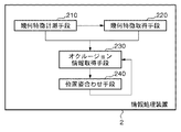
図6は、本実施形態における情報処理装置2の構成を示している。同図に示すように、情報処理装置2は、幾何特徴計測手段210、幾何特徴取得手段220、オクルージョン情報取得手段230および位置合わせ手段240を備える。以下、情報処理装置2を構成する各部について説明する。
FIG. 6 shows the configuration of the
幾何特徴計測手段210は、実施形態1の幾何特徴計測手段110と同様に対象物体の幾何特徴部分の位置及び法線方向(面の向き)を複数計測する。本実施形態では、3次元点の位置及び法線方向を計測することとするが、属性として位置及び面の向きを持っていればどんな幾何特徴部分であっても良い。また対象物体の幾何特徴部分の位置及び法線方向は記憶装置に保存しておいたものを取得しても良い。以降では、幾何特徴計測手段210で計測された幾何特徴部分群を計測データ1とする。
Similar to the geometric
幾何特徴取得手段220では、実施形態1の幾何特徴計測手段110と同様に対象物体の幾何特徴部分の位置及び法線方向(面の向き)を複数の幾何特徴部分について計測し、計測データ1と対応付けた幾何特徴部分の組を出力する。本実施形態では3次元点の位置及び法線方向を計測することとするが、属性として位置及び面の向きを持っていればどんな幾何特徴部分であっても良い。対象物体の幾何特徴部分の位置及び法線方向は記憶装置に保存しておいたものを取得しても良いが、計測データ1とは異なる幾何特徴部分群を取得する。以降では、幾何特徴取得手段220で取得した幾何特徴部分群を計測データ2とする。幾何特徴部分群取得後、実施形態1の幾何特徴取得手段120で行った対応探索と同様に、計測データ1と計測データ2の間の対応探索を行い、対応点の組を出力する。
The geometric
オクルージョン情報取得手段230では、実施形態1のオクルージョン情報取得手段130と同様に対応付けられている幾何特徴部分間のオクルージョン情報を取得する。オクルージョン情報取得手段130との違いは、判定対象が計測データと形状モデルの幾何特徴部分の組から、計測データ1及び計測データ2の計測データ同士の幾何特徴部分の組になることであるが、その処理の仕方は同様である。
The occlusion
位置合わせ手段240は、オクルージョン情報取得手段230にてオクルージョンしていないと判定された幾何特徴部分の組を用いて、計測データ1及び計測データ2の位置合わせを行う。位置合わせは、幾何特徴部分の組の3次元空間中での距離に基づく評価関数を最小化することによって行う。その他、計測データ1及び計測データ2との間の差異に基づく評価関数に基づいて対象物体の位置及び姿勢を推定する手法であればいかなるものであっても本発明の本質を損なうものではない。また、オクルージョン情報取得手段230にて幾何特徴部分の組毎にオクルージョンの確からしさを示す数値を算出する場合、その数値を重みとして評価関数に掛け合わせたものを最小化しても良い。
The
図7は本実施形態における複数の3次元点群同士を位置合わせの処理手順を示すフローチャートである。この処理では、計測データ1及び計測データ2の一方を基準データとし、他方の計測データの基準データに対する相対位置姿勢を反復演算により繰り返し補正することにより算出し、計測データ同士の位置合わせを行う。位置合わせされた計測データを1つの座標系に統合した3次元点群が対象物体の3次元形状を表す点群となる。
FIG. 7 is a flowchart showing a processing procedure for aligning a plurality of three-dimensional point groups in this embodiment. In this process, one of the measurement data 1 and the
S2000およびS2010において、幾何特徴計測手段210及び幾何特徴取得手段220は、それぞれ対象物体の幾何特徴部分の計測データを計測し取得する。計測データには計測した対象物体の幾何特徴部分(3次元点)の位置及びその位置における法線方向及び計測視点の概略位置姿勢が含まれる。本実施形態では、計測視点の概略位置姿勢としてGPS及び慣性センサを用いて計測した値が与えられる。しかしながら概略位置姿勢は計測データ間の概略の相対位置姿勢が分かれば良く、これを実現できるセンサならどのセンサを用いて計測しても良い。また概略位置姿勢を手動で与えても良いし、計測データ間の対応を手動で与えて算出しても良い。
In S2000 and S2010, the geometric
S2020において、幾何特徴取得手段220は、S2000およびS2010で計測した計測データ間の幾何特徴部分群の対応付けを行う。本実施形態では最近傍探索を用い、概略位置姿勢に基づき一方の計測データの幾何特徴部分に最も近い他方の計測データの幾何特徴部分を対応付ける。ただし対応探索方法はこれに限るものではなく、従来技術による画像上に投影することにより幾何特徴部分を対応付ける方法を用いても良い。
In S2020, the geometric
S2030において、オクルージョン情報取得手段230は、S2020で対応付けた計測データ間の幾何特徴部分の組のオクルージョン情報を取得する。本実施形態ではオクルージョン情報として各対応する組毎にオクルージョンの有無を判定する。しかしながらS2040でオクルージョン情報を重みとして利用する場合には、オクルージョンの確からしさを表す数値を算出しても良い。
In S2030, the occlusion
S2040において、位置合わせ手段240は、幾何特徴部分の組を用いて非線型最適化手法により計測データを計測した際の計測位置及び姿勢を更新する。この処理では、対応付けた計測点群の組の3次元空間中での距離をGauss -Newton法により最小化する。そしてS2050で収束と判定されるまで、各計測データの計測位置姿勢を反復演算により繰り返し補正する。なお、計測位置姿勢の算出方法はこれに限るものではない。従来のLevenberg -Marquardt法や最急降下法などの最適化手法や共役勾配法など、他の非線型最適化計算手法を用いてもかまわない。
In step S2040, the
S2050において 位置合わせ手段240は、収束判定を行い、収束していれば終了し、そうでなければ計測位置姿勢を更新してS1020 に戻る。ここでは、計測位置姿勢の更新前後の誤差ベクトルの二乗和の差がほぼゼロである場合に収束したと判定される。ただし判定条件はこれに限るものではない。例えば計測位置姿勢の更新量がほぼゼロである場合に収束と判定しても良い。収束後、推定した計測位置姿勢に基づいて計測データを1つの座標系に統合し、3次元形状を表す幾何特徴部分の集合として出力する。
In S2050, the
本実施形態では2つの3次元点群同士を位置合わせする場合について説明した。しかしながら計測データ群は2つに限るものではない。計測データ群は3つ以上であっても良く、複数の計測データ群を扱う場合は任意の2つの計測データ群に対して本実施形態を適用すれば良い。 In the present embodiment, the case where two three-dimensional point groups are aligned has been described. However, the number of measurement data groups is not limited to two. There may be three or more measurement data groups, and when dealing with a plurality of measurement data groups, the present embodiment may be applied to any two measurement data groups.
以上述べたように、実施形態1および2に記載された発明の構成をとることで、本発明は、物体の3次元形状計測や、物体認識、ロボットの自己位置推定、ロボットと物体との間の相対的な位置及び姿勢の推定に利用することができる。 As described above, by adopting the configuration of the invention described in the first and second embodiments, the present invention can measure the three-dimensional shape of an object, recognize an object, estimate the position of the robot, Can be used to estimate the relative position and orientation of the.
(その他の実施例)
また、本発明は、以下の処理を実行することによっても実現される。即ち、上述した実施形態の機能を実現するソフトウェア(プログラム)を、ネットワーク又は各種記憶媒体を介してシステム或いは装置に供給し、そのシステム或いは装置のコンピュータ(またはCPUやMPU等)がプログラムを読み出して実行する処理である。
(Other examples)
The present invention can also be realized by executing the following processing. That is, software (program) that realizes the functions of the above-described embodiments is supplied to a system or apparatus via a network or various storage media, and a computer (or CPU, MPU, etc.) of the system or apparatus reads the program. It is a process to be executed.
Claims (12)
前記第1の位置とは異なる第2の位置に配置された前記対象物体の形状モデルから、前記対象物体の前記複数の幾何特徴部分に対応する部分の複数の法線を取得する第2取得手段と、
前記対象物体と前記形状モデルとの対応する幾何特徴部分の組について、前記第1取得手段で取得された法線と、前記第2取得手段で取得された法線とに基づいて幾何特徴部分におけるオクルージョンの発生の有無を判定する判定手段と
を備えることを特徴とする情報処理装置。 From the target object disposed in a first position, a first obtaining means for obtaining the normals definitive multiple geometric features moiety and said plurality of geometric features worth of,
Second acquisition for acquiring a plurality of normal of different from the shape model arranged the object in the second position, the portion corresponding to the plurality of geometric features fraction of the target object from the first position Means,
The corresponding set of geometric characteristic portion of the object and the shape model, in the the normal acquired by the first acquisition means, the geometric feature portion on the basis of the normal line obtained in said second obtaining means An information processing apparatus comprising: determination means for determining whether or not occlusion occurs.
前記判定手段は、前記算出手段で算出した方向の差に基づいて、幾何特徴部分におけるオクルージョンの発生の有無を判定することを特徴とする請求項1に記載の情報処理装置。The information processing apparatus according to claim 1, wherein the determination unit determines whether or not occlusion occurs in the geometric feature portion based on a difference in direction calculated by the calculation unit.
前記第1の位置とは異なる第2の位置にある、前記第1の対象物体の同形状の第2の対象物体から、前記第1の対象物体の前記複数の幾何特徴部分に対応する部分の複数の法線を取得する第2取得手段と、
前記第1の位置における前記第1の対象物体と前記第2の位置における前記第2の対象物体との対応する幾何特徴部分の組について、前記第1取得手段で取得された法線と、前記第2取得手段で取得された法線とに基づいて、幾何特徴部分におけるオクルージョンの発生の有無を判定する判定手段と
を備えることを特徴とする情報処理装置。 When the first object is in the first position, the first obtaining means for obtaining a plurality of geometric characteristic portion from the target object of the first, the normals definitive in plural geometric feature amount of,
In different second position from the first position, the first from the second target object having the same shape of the object, the portion corresponding to the plurality of geometric features fraction of the first object Second acquisition means for acquiring a plurality of normals of
For a set of corresponding geometric feature portions of the first target object at the first position and the second target object at the second position, the normal obtained by the first acquisition means, An information processing apparatus comprising: a determination unit that determines whether or not occlusion occurs in the geometric feature portion based on the normal acquired by the second acquisition unit.
前記判定手段は、前記算出手段で算出した方向の差に基づいて、幾何特徴部分におけるオクルージョンの発生の有無を判定することを特徴とする請求項7に記載の情報処理装置。The information processing apparatus according to claim 7, wherein the determination unit determines whether or not occlusion occurs in the geometric feature portion based on a difference in direction calculated by the calculation unit.
第2取得手段が、前記第1の位置とは異なる第2の位置に配置された前記対象物体の形状モデルから、前記対象物体の前記複数の幾何特徴部分に対応する部分の複数の法線を取得する第2取得工程と、
判定手段が、前記対象物体と前記形状モデルとの対応する幾何特徴部分の組について、前記第1取得工程で取得された法線と、前記第2取得手段で取得された法線とに基づいて幾何特徴部分におけるオクルージョンの発生の有無を判定する判定工程と
を備えることを特徴とする情報処理装置の処理方法。 First acquisition means, from a target object disposed in a first position, a first obtaining step of obtaining a normal line definitive geometric feature amount of the plurality of geometric features part and plurality of,
Second acquisition means, from the shape model of said object placed at different second position from the first position, a plurality of normal line of the portion corresponding to the plurality of geometric features fraction of the target object A second acquisition step of acquiring
Determining means, said set for the corresponding geometric characteristic portion of the target object and the shape model, said the normal obtained by the first acquisition step, based on the normal line obtained in said second obtaining means And a determination step of determining whether or not occlusion occurs in the geometric feature portion .
第2取得手段が、前記第1の位置とは異なる第2の位置にある、前記第1の対象物体の同形状の第2の対象物体から、前記第1の対象物体の前記複数の幾何特徴部分に対応する部分の複数の法線を取得する第2取得工程と、
判定手段が、前記第1の位置における前記第1の対象物体と前記第2の位置における前記第2の対象物体との対応する幾何特徴部分の組について、前記第1取得工程で取得された法線と、前記第2取得工程で取得された法線とに基づいて、幾何特徴部分におけるオクルージョンの発生の有無を判定する判定工程と
を備えることを特徴とする情報処理装置の処理方法。 The first obtaining unit, the first target object when in the first position, to obtain a plurality of geometric characteristic portion from the target object of the first, the normals definitive geometric feature amount of the plurality of 1 Acquisition process;
The plurality of geometric features of the first target object from a second target object having the same shape as the first target object, wherein the second acquisition means is at a second position different from the first position. a second acquisition step of acquiring a plurality of normal line of the portion corresponding to the part amount,
The determination means obtains the method acquired in the first acquisition step with respect to a set of corresponding geometric feature portions of the first target object at the first position and the second target object at the second position. A processing method for an information processing apparatus, comprising: a determination step of determining whether or not occlusion occurs in a geometric feature portion based on a line and a normal line acquired in the second acquisition step .
Priority Applications (3)
| Application Number | Priority Date | Filing Date | Title |
|---|---|---|---|
| JP2010139947A JP5615055B2 (en) | 2010-06-18 | 2010-06-18 | Information processing apparatus and processing method thereof |
| PCT/JP2011/063755 WO2011158886A1 (en) | 2010-06-18 | 2011-06-09 | Information processing apparatus and processing method thereof |
| US13/701,281 US8971576B2 (en) | 2010-06-18 | 2011-06-09 | Information processing apparatus and processing method thereof |
Applications Claiming Priority (1)
| Application Number | Priority Date | Filing Date | Title |
|---|---|---|---|
| JP2010139947A JP5615055B2 (en) | 2010-06-18 | 2010-06-18 | Information processing apparatus and processing method thereof |
Publications (3)
| Publication Number | Publication Date |
|---|---|
| JP2012003638A JP2012003638A (en) | 2012-01-05 |
| JP2012003638A5 JP2012003638A5 (en) | 2013-08-01 |
| JP5615055B2 true JP5615055B2 (en) | 2014-10-29 |
Family
ID=44627682
Family Applications (1)
| Application Number | Title | Priority Date | Filing Date |
|---|---|---|---|
| JP2010139947A Active JP5615055B2 (en) | 2010-06-18 | 2010-06-18 | Information processing apparatus and processing method thereof |
Country Status (3)
| Country | Link |
|---|---|
| US (1) | US8971576B2 (en) |
| JP (1) | JP5615055B2 (en) |
| WO (1) | WO2011158886A1 (en) |
Families Citing this family (11)
| Publication number | Priority date | Publication date | Assignee | Title |
|---|---|---|---|---|
| JP5671281B2 (en) | 2010-08-20 | 2015-02-18 | キヤノン株式会社 | Position / orientation measuring apparatus, control method and program for position / orientation measuring apparatus |
| JP6004809B2 (en) * | 2012-03-13 | 2016-10-12 | キヤノン株式会社 | Position / orientation estimation apparatus, information processing apparatus, and information processing method |
| JP6092530B2 (en) | 2012-06-18 | 2017-03-08 | キヤノン株式会社 | Image processing apparatus and image processing method |
| US9256788B2 (en) * | 2012-11-02 | 2016-02-09 | Qualcomm Incorporated | Method for initializing and solving the local geometry or surface normals of surfels using images in a parallelizable architecture |
| JP6325896B2 (en) * | 2014-03-28 | 2018-05-16 | 株式会社キーエンス | Optical coordinate measuring device |
| JP6906304B2 (en) * | 2015-12-30 | 2021-07-21 | ダッソー システムズDassault Systemes | Embedded frequency-based exploration and 3D graphical data processing |
| US20180268614A1 (en) * | 2017-03-16 | 2018-09-20 | General Electric Company | Systems and methods for aligning pmi object on a model |
| JP7257752B2 (en) * | 2018-07-31 | 2023-04-14 | 清水建設株式会社 | Position detection system |
| JP7111297B2 (en) * | 2018-11-26 | 2022-08-02 | 株式会社豊田中央研究所 | Positional deviation correction device and program |
| KR20220039059A (en) * | 2020-09-21 | 2022-03-29 | 엘지전자 주식회사 | Dishwasher and method for obtaining three-dimensional image thereof |
| CN112083415B (en) * | 2020-10-12 | 2021-10-29 | 吉林大学 | Millimeter wave radar model target visibility judgment method based on 3D information |
Family Cites Families (33)
| Publication number | Priority date | Publication date | Assignee | Title |
|---|---|---|---|---|
| JPH09178463A (en) * | 1995-12-26 | 1997-07-11 | Nikon Corp | Multidimensional coordinate measuring device |
| US6858826B2 (en) * | 1996-10-25 | 2005-02-22 | Waveworx Inc. | Method and apparatus for scanning three-dimensional objects |
| US6406292B1 (en) * | 1999-05-13 | 2002-06-18 | Align Technology, Inc. | System for determining final position of teeth |
| US7068825B2 (en) * | 1999-03-08 | 2006-06-27 | Orametrix, Inc. | Scanning system and calibration method for capturing precise three-dimensional information of objects |
| JP2001118082A (en) * | 1999-10-15 | 2001-04-27 | Toshiba Corp | Plotting arithmetic processor |
| US6767208B2 (en) * | 2002-01-10 | 2004-07-27 | Align Technology, Inc. | System and method for positioning teeth |
| US7787692B2 (en) * | 2003-09-25 | 2010-08-31 | Fujifilm Corporation | Image processing apparatus, image processing method, shape diagnostic apparatus, shape diagnostic method and program |
| US7327857B2 (en) * | 2004-03-09 | 2008-02-05 | General Electric Company | Non-contact measurement method and apparatus |
| US7230620B2 (en) * | 2004-08-05 | 2007-06-12 | Mitsubishi Electric Research Laboratories, Inc. | Rendering deformable and animated surface reflectance fields |
| DK1808129T3 (en) * | 2004-09-24 | 2017-08-28 | Icat Corp | Device for detecting cross-sectional information |
| GB0520829D0 (en) * | 2005-10-13 | 2005-11-23 | Univ Cambridge Tech | Image processing methods and apparatus |
| GB0608841D0 (en) * | 2006-05-04 | 2006-06-14 | Isis Innovation | Scanner system and method for scanning |
| US7844356B2 (en) * | 2006-07-19 | 2010-11-30 | Align Technology, Inc. | System and method for automatic construction of orthodontic reference objects |
| US7813592B2 (en) * | 2006-08-09 | 2010-10-12 | Siemens Medical Solutions Usa, Inc. | System and method for non-rigid multi-modal registration on the GPU |
| JP4757142B2 (en) * | 2006-08-10 | 2011-08-24 | キヤノン株式会社 | Imaging environment calibration method and information processing apparatus |
| GB0615956D0 (en) * | 2006-08-11 | 2006-09-20 | Univ Heriot Watt | Optical imaging of physical objects |
| US8054471B2 (en) | 2006-09-15 | 2011-11-08 | Sciammarella Cesar A | System and method for analyzing displacements and contouring of surfaces |
| GB0707454D0 (en) * | 2007-04-18 | 2007-05-23 | Materialise Dental Nv | Computer-assisted creation of a custom tooth set-up using facial analysis |
| JP5120926B2 (en) * | 2007-07-27 | 2013-01-16 | 有限会社テクノドリーム二十一 | Image processing apparatus, image processing method, and program |
| GB2458927B (en) * | 2008-04-02 | 2012-11-14 | Eykona Technologies Ltd | 3D Imaging system |
| WO2009147814A1 (en) * | 2008-06-02 | 2009-12-10 | パナソニック株式会社 | Image processing device, method, and computer program for generating normal (line) information, and viewpoint-converted image generation device |
| JP5317169B2 (en) * | 2008-06-13 | 2013-10-16 | 洋 川崎 | Image processing apparatus, image processing method, and program |
| JP2010033298A (en) * | 2008-07-28 | 2010-02-12 | Namco Bandai Games Inc | Program, information storage medium, and image generation system |
| TW201017578A (en) * | 2008-10-29 | 2010-05-01 | Chunghwa Picture Tubes Ltd | Method for rebuilding 3D surface model |
| JP2010139947A (en) | 2008-12-15 | 2010-06-24 | Pioneer Electronic Corp | Image signal processing method and image signal processing device |
| US8717578B2 (en) * | 2009-04-10 | 2014-05-06 | Omron Corporation | Profilometer, measuring apparatus, and observing apparatus |
| US20100259746A1 (en) * | 2009-04-10 | 2010-10-14 | Omron Corporation | Profilometer |
| JP5430456B2 (en) * | 2010-03-16 | 2014-02-26 | キヤノン株式会社 | Geometric feature extraction device, geometric feature extraction method, program, three-dimensional measurement device, object recognition device |
| JP5170154B2 (en) * | 2010-04-26 | 2013-03-27 | オムロン株式会社 | Shape measuring apparatus and calibration method |
| JP5343042B2 (en) * | 2010-06-25 | 2013-11-13 | 株式会社トプコン | Point cloud data processing apparatus and point cloud data processing program |
| EP2426612B1 (en) * | 2010-08-27 | 2019-03-13 | Dassault Systèmes | Watermarking of a 3D modeled object |
| US8818773B2 (en) * | 2010-10-25 | 2014-08-26 | Vistaprint Schweiz Gmbh | Embroidery image rendering using parametric texture mapping |
| WO2013134584A1 (en) * | 2012-03-08 | 2013-09-12 | Hugomed Llc | 3d design and fabrication system for implants |
-
2010
- 2010-06-18 JP JP2010139947A patent/JP5615055B2/en active Active
-
2011
- 2011-06-09 US US13/701,281 patent/US8971576B2/en active Active
- 2011-06-09 WO PCT/JP2011/063755 patent/WO2011158886A1/en active Application Filing
Also Published As
| Publication number | Publication date |
|---|---|
| US8971576B2 (en) | 2015-03-03 |
| US20130094706A1 (en) | 2013-04-18 |
| JP2012003638A (en) | 2012-01-05 |
| WO2011158886A1 (en) | 2011-12-22 |
Similar Documents
| Publication | Publication Date | Title |
|---|---|---|
| JP5615055B2 (en) | Information processing apparatus and processing method thereof | |
| JP5393318B2 (en) | Position and orientation measurement method and apparatus | |
| JP5839929B2 (en) | Information processing apparatus, information processing system, information processing method, and program | |
| US20200096317A1 (en) | Three-dimensional measurement apparatus, processing method, and non-transitory computer-readable storage medium | |
| JP6370038B2 (en) | Position and orientation measurement apparatus and method | |
| JP5297403B2 (en) | Position / orientation measuring apparatus, position / orientation measuring method, program, and storage medium | |
| JP6180087B2 (en) | Information processing apparatus and information processing method | |
| JP5618569B2 (en) | Position and orientation estimation apparatus and method | |
| JP6736257B2 (en) | Information processing device, information processing method, and program | |
| JP5924862B2 (en) | Information processing apparatus, information processing method, and program | |
| JP5627325B2 (en) | Position / orientation measuring apparatus, position / orientation measuring method, and program | |
| JP6324025B2 (en) | Information processing apparatus and information processing method | |
| JP6677522B2 (en) | Information processing apparatus, control method for information processing apparatus, and program | |
| WO2012008618A1 (en) | Position/orientation measurement apparatus, measurement processing method thereof, and non-transitory computer-readable storage medium | |
| JP6626338B2 (en) | Information processing apparatus, control method for information processing apparatus, and program | |
| JP2020125960A (en) | Moving object position estimating device and moving object position estimating program | |
| JP5698815B2 (en) | Information processing apparatus, information processing apparatus control method, and program | |
| JP6066562B2 (en) | Measuring device, measuring method and program | |
| JP6040264B2 (en) | Information processing apparatus, information processing apparatus control method, and program | |
| JP6766229B2 (en) | Position and posture measuring device and method | |
| Bergamini et al. | Digital camera calibration, relative orientation and essential matrix parameters | |
| CN118196286A (en) | Method and device for determining three-dimensional scanning waypoints, electronic equipment and storage medium | |
| JP2012150655A (en) | Device and program for estimating motion |
Legal Events
| Date | Code | Title | Description |
|---|---|---|---|
| A521 | Request for written amendment filed |
Free format text: JAPANESE INTERMEDIATE CODE: A523 Effective date: 20130618 |
|
| A621 | Written request for application examination |
Free format text: JAPANESE INTERMEDIATE CODE: A621 Effective date: 20130618 |
|
| TRDD | Decision of grant or rejection written | ||
| A01 | Written decision to grant a patent or to grant a registration (utility model) |
Free format text: JAPANESE INTERMEDIATE CODE: A01 Effective date: 20140811 |
|
| A61 | First payment of annual fees (during grant procedure) |
Free format text: JAPANESE INTERMEDIATE CODE: A61 Effective date: 20140909 |
|
| R151 | Written notification of patent or utility model registration |
Ref document number: 5615055 Country of ref document: JP Free format text: JAPANESE INTERMEDIATE CODE: R151 |