EP2639468A2 - Rolling bearing unit - Google Patents
Rolling bearing unit Download PDFInfo
- Publication number
- EP2639468A2 EP2639468A2 EP13158768.5A EP13158768A EP2639468A2 EP 2639468 A2 EP2639468 A2 EP 2639468A2 EP 13158768 A EP13158768 A EP 13158768A EP 2639468 A2 EP2639468 A2 EP 2639468A2
- Authority
- EP
- European Patent Office
- Prior art keywords
- cylindrical portion
- outer ring
- metal core
- fitted
- folded
- Prior art date
- Legal status (The legal status is an assumption and is not a legal conclusion. Google has not performed a legal analysis and makes no representation as to the accuracy of the status listed.)
- Granted
Links
- 238000005096 rolling process Methods 0.000 title claims description 26
- 239000002184 metal Substances 0.000 claims abstract description 41
- 238000007789 sealing Methods 0.000 claims description 18
- XLYOFNOQVPJJNP-UHFFFAOYSA-N water Substances O XLYOFNOQVPJJNP-UHFFFAOYSA-N 0.000 description 3
Images


Classifications
-
- F—MECHANICAL ENGINEERING; LIGHTING; HEATING; WEAPONS; BLASTING
- F16—ENGINEERING ELEMENTS AND UNITS; GENERAL MEASURES FOR PRODUCING AND MAINTAINING EFFECTIVE FUNCTIONING OF MACHINES OR INSTALLATIONS; THERMAL INSULATION IN GENERAL
- F16C—SHAFTS; FLEXIBLE SHAFTS; ELEMENTS OR CRANKSHAFT MECHANISMS; ROTARY BODIES OTHER THAN GEARING ELEMENTS; BEARINGS
- F16C33/00—Parts of bearings; Special methods for making bearings or parts thereof
- F16C33/72—Sealings
- F16C33/76—Sealings of ball or roller bearings
- F16C33/78—Sealings of ball or roller bearings with a diaphragm, disc, or ring, with or without resilient members
- F16C33/7886—Sealings of ball or roller bearings with a diaphragm, disc, or ring, with or without resilient members mounted outside the gap between the inner and outer races, e.g. sealing rings mounted to an end face or outer surface of a race
-
- F—MECHANICAL ENGINEERING; LIGHTING; HEATING; WEAPONS; BLASTING
- F16—ENGINEERING ELEMENTS AND UNITS; GENERAL MEASURES FOR PRODUCING AND MAINTAINING EFFECTIVE FUNCTIONING OF MACHINES OR INSTALLATIONS; THERMAL INSULATION IN GENERAL
- F16C—SHAFTS; FLEXIBLE SHAFTS; ELEMENTS OR CRANKSHAFT MECHANISMS; ROTARY BODIES OTHER THAN GEARING ELEMENTS; BEARINGS
- F16C19/00—Bearings with rolling contact, for exclusively rotary movement
- F16C19/22—Bearings with rolling contact, for exclusively rotary movement with bearing rollers essentially of the same size in one or more circular rows, e.g. needle bearings
- F16C19/34—Bearings with rolling contact, for exclusively rotary movement with bearing rollers essentially of the same size in one or more circular rows, e.g. needle bearings for both radial and axial load
- F16C19/38—Bearings with rolling contact, for exclusively rotary movement with bearing rollers essentially of the same size in one or more circular rows, e.g. needle bearings for both radial and axial load with two or more rows of rollers
- F16C19/383—Bearings with rolling contact, for exclusively rotary movement with bearing rollers essentially of the same size in one or more circular rows, e.g. needle bearings for both radial and axial load with two or more rows of rollers with tapered rollers, i.e. rollers having essentially the shape of a truncated cone
- F16C19/385—Bearings with rolling contact, for exclusively rotary movement with bearing rollers essentially of the same size in one or more circular rows, e.g. needle bearings for both radial and axial load with two or more rows of rollers with tapered rollers, i.e. rollers having essentially the shape of a truncated cone with two rows, i.e. double-row tapered roller bearings
-
- F—MECHANICAL ENGINEERING; LIGHTING; HEATING; WEAPONS; BLASTING
- F16—ENGINEERING ELEMENTS AND UNITS; GENERAL MEASURES FOR PRODUCING AND MAINTAINING EFFECTIVE FUNCTIONING OF MACHINES OR INSTALLATIONS; THERMAL INSULATION IN GENERAL
- F16C—SHAFTS; FLEXIBLE SHAFTS; ELEMENTS OR CRANKSHAFT MECHANISMS; ROTARY BODIES OTHER THAN GEARING ELEMENTS; BEARINGS
- F16C33/00—Parts of bearings; Special methods for making bearings or parts thereof
- F16C33/72—Sealings
- F16C33/76—Sealings of ball or roller bearings
- F16C33/78—Sealings of ball or roller bearings with a diaphragm, disc, or ring, with or without resilient members
- F16C33/7803—Sealings of ball or roller bearings with a diaphragm, disc, or ring, with or without resilient members suited for particular types of rolling bearings
- F16C33/7813—Sealings of ball or roller bearings with a diaphragm, disc, or ring, with or without resilient members suited for particular types of rolling bearings for tapered roller bearings
-
- F—MECHANICAL ENGINEERING; LIGHTING; HEATING; WEAPONS; BLASTING
- F16—ENGINEERING ELEMENTS AND UNITS; GENERAL MEASURES FOR PRODUCING AND MAINTAINING EFFECTIVE FUNCTIONING OF MACHINES OR INSTALLATIONS; THERMAL INSULATION IN GENERAL
- F16C—SHAFTS; FLEXIBLE SHAFTS; ELEMENTS OR CRANKSHAFT MECHANISMS; ROTARY BODIES OTHER THAN GEARING ELEMENTS; BEARINGS
- F16C33/00—Parts of bearings; Special methods for making bearings or parts thereof
- F16C33/72—Sealings
- F16C33/76—Sealings of ball or roller bearings
- F16C33/78—Sealings of ball or roller bearings with a diaphragm, disc, or ring, with or without resilient members
- F16C33/7816—Details of the sealing or parts thereof, e.g. geometry, material
- F16C33/783—Details of the sealing or parts thereof, e.g. geometry, material of the mounting region
-
- F—MECHANICAL ENGINEERING; LIGHTING; HEATING; WEAPONS; BLASTING
- F16—ENGINEERING ELEMENTS AND UNITS; GENERAL MEASURES FOR PRODUCING AND MAINTAINING EFFECTIVE FUNCTIONING OF MACHINES OR INSTALLATIONS; THERMAL INSULATION IN GENERAL
- F16C—SHAFTS; FLEXIBLE SHAFTS; ELEMENTS OR CRANKSHAFT MECHANISMS; ROTARY BODIES OTHER THAN GEARING ELEMENTS; BEARINGS
- F16C33/00—Parts of bearings; Special methods for making bearings or parts thereof
- F16C33/72—Sealings
- F16C33/76—Sealings of ball or roller bearings
- F16C33/80—Labyrinth sealings
- F16C33/805—Labyrinth sealings in addition to other sealings, e.g. dirt guards to protect sealings with sealing lips
-
- F—MECHANICAL ENGINEERING; LIGHTING; HEATING; WEAPONS; BLASTING
- F16—ENGINEERING ELEMENTS AND UNITS; GENERAL MEASURES FOR PRODUCING AND MAINTAINING EFFECTIVE FUNCTIONING OF MACHINES OR INSTALLATIONS; THERMAL INSULATION IN GENERAL
- F16C—SHAFTS; FLEXIBLE SHAFTS; ELEMENTS OR CRANKSHAFT MECHANISMS; ROTARY BODIES OTHER THAN GEARING ELEMENTS; BEARINGS
- F16C19/00—Bearings with rolling contact, for exclusively rotary movement
- F16C19/22—Bearings with rolling contact, for exclusively rotary movement with bearing rollers essentially of the same size in one or more circular rows, e.g. needle bearings
- F16C19/34—Bearings with rolling contact, for exclusively rotary movement with bearing rollers essentially of the same size in one or more circular rows, e.g. needle bearings for both radial and axial load
- F16C19/38—Bearings with rolling contact, for exclusively rotary movement with bearing rollers essentially of the same size in one or more circular rows, e.g. needle bearings for both radial and axial load with two or more rows of rollers
- F16C19/383—Bearings with rolling contact, for exclusively rotary movement with bearing rollers essentially of the same size in one or more circular rows, e.g. needle bearings for both radial and axial load with two or more rows of rollers with tapered rollers, i.e. rollers having essentially the shape of a truncated cone
- F16C19/385—Bearings with rolling contact, for exclusively rotary movement with bearing rollers essentially of the same size in one or more circular rows, e.g. needle bearings for both radial and axial load with two or more rows of rollers with tapered rollers, i.e. rollers having essentially the shape of a truncated cone with two rows, i.e. double-row tapered roller bearings
- F16C19/386—Bearings with rolling contact, for exclusively rotary movement with bearing rollers essentially of the same size in one or more circular rows, e.g. needle bearings for both radial and axial load with two or more rows of rollers with tapered rollers, i.e. rollers having essentially the shape of a truncated cone with two rows, i.e. double-row tapered roller bearings in O-arrangement
-
- F—MECHANICAL ENGINEERING; LIGHTING; HEATING; WEAPONS; BLASTING
- F16—ENGINEERING ELEMENTS AND UNITS; GENERAL MEASURES FOR PRODUCING AND MAINTAINING EFFECTIVE FUNCTIONING OF MACHINES OR INSTALLATIONS; THERMAL INSULATION IN GENERAL
- F16C—SHAFTS; FLEXIBLE SHAFTS; ELEMENTS OR CRANKSHAFT MECHANISMS; ROTARY BODIES OTHER THAN GEARING ELEMENTS; BEARINGS
- F16C2326/00—Articles relating to transporting
- F16C2326/01—Parts of vehicles in general
- F16C2326/02—Wheel hubs or castors
Definitions
- the invention relates generally to a rolling bearing unit, and more specifically to a rolling bearing unit that includes a sealing device.
- a rolling bearing unit that includes a sealing device is used as a bearing unit that is used in an environment in which water is likely to enter the bearing unit from the outside, such as a bearing unit for a wheel of a vehicle.
- a rolling bearing unit that includes a sealing device Japanese Patent Application Publication No. 2007-177814 ( JP 2007-177814 A ) describes a rolling bearing unit that includes an outer ring, an inner ring, a plurality of rolling elements, and a sealing device that is disposed at at least one of a position between one end portion of the outer ring and one end portion of the inner ring, and a position between the other end portion of the outer ring and the other end portion of the inner ring.
- the sealing device described in JP 2007-177814 A includes a metal core and an elastic seal.
- the metal core has a cylindrical portion that is fitted to an outer periphery of the outer ring.
- the elastic seal is fitted to the metal core.
- the cylindrical portion of the metal core is fitted to the outer ring by interference fit to prevent entry of water into the rolling bearing unit through a joint between the cylindrical portion and the metal core.
- the metal core is formed by press working, and therefore the accuracy of the metal core is not sufficiently high. Therefore, when the cylindrical portion is fitted to the outer ring, the cylindrical portion may flare out at its end portion and the end portion may be apart from the metal core. In this case, the waterproof property at the joint is reduced.
- An aspect of the invention relates to a rolling bearing unit, including: an outer ring; an inner ring; a plurality of rolling elements; and a sealing device that is disposed at at least one of a position between one end portion of the outer ring and one end portion of the inner ring and a position between the other end portion of the outer ring and the other end portion of the inner ring, the sealing device including a metal core that has a cylindrical portion that is fitted to an outer periphery of the outer ring, and an elastic seal that is fitted to the metal core.
- An inner diameter of the cylindrical portion of the metal core is set to such a value that the cylindrical portion is fitted to the outer ring by interference fit.
- An inner periphery of an end portion of the cylindrical portion is larger in diameter than an inner periphery of a portion of the cylindrical portion, which is fitted to the outer ring.
- the elastic seal has a cylindrical portion that is in close contact with an outer periphery of the cylindrical portion of the metal core and a folded-back portion that extends from the cylindrical portion, and the folded-back portion is compressively deformed by being sandwiched between the inner periphery of the end portion of the cylindrical portion of the metal core and the outer periphery of the outer ring.
- FIG. 1 and FIG. 2 each show a rolling bearing unit according to a first embodiment of the invention.
- a rolling bearing unit 1 is suitable for use in, for example, a hub unit for a vehicle.
- the rolling bearing unit 1 includes an outer ring 2, an inner ring 3, a plurality of tapered rollers (rolling elements) 4, cages 5, and sealing devices 6, 7.
- the tapered rollers 4 are arranged in two rows between the outer ring 2 and the inner ring 3.
- the cages 5 hold the tapered rollers 4.
- the sealing device 6 is disposed between the outer ring 2 and the inner ring 3, at a position on the inboard side
- the sealing device 7 is disposed between the outer ring 2 and the inner ring 3, at a position on the outboard side.
- a flange 8, to which a wheel is fitted, is formed on the outboard-side of the inner ring 3.
- a flange 9, to which a knuckle that is a vehicle body-side member is fitted, is formed on the outer ring 2.
- the inner ring 3 has large ribs 3a, 3b at its respective end portions.
- the large ribs 3a, 3b receive the tapered rollers 4.
- the outboard-side flange 8 extends radially outward from a portion near the outboard-side large rib 3b of the inner ring 3 with a small clearance left between the outboard-side flange 8 and an outboard-side end face of the outer ring 2.
- the inboard-side sealing device 6 is a so-called pack seal, and is disposed between and fitted to an inner periphery of the outer ring 2 and an outer periphery of the inner ring 3.
- the outboard-side sealing device 7 is a sealing device that is fitted to an outer periphery 2a of the outer ring 2.
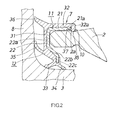
- FIG. 2 shows the outboard-side sealing device 7 that is main part of the rolling bearing unit 1 according to the invention.
- the sealing device 7 includes a metal core 11 that has an L-shaped section and is fitted to the outer ring 2, and an elastic seal 12 that is fitted to the metal core 11.
- the metal core 11 has a cylindrical portion 21 fitted to the outer periphery 2a of the outer ring 2, and an annular portion 22 that extends radially inward from an axially outer end of the cylindrical portion 21.
- the inner diameter of the cylindrical portion 21 of the core metal 11 is set to such a value that the cylindrical portion 21 is fitted to the outer ring 2 by interference fit.
- An inner periphery 21a of an inboard-side end portion of the cylindrical portion 21 is larger in diameter than an inner periphery of an outboard-side portion of the cylindrical portion 21, which is fitted to the outer ring 2.
- the annular portion 22 of the metal core 11 has an outer annular portion 22a, a tapered portion 22b, and an inner annular portion 22c.
- the outer annular portion 22a is in contact with the end face of the outer ring 2.
- the tapered portion 22b extends axially inward and radially inward from a radially inner end of the outer annular portion 22a.
- the inner annular portion 22c extends radially inward from a radially inner end of the tapered portion 22b.
- the elastic seal 12 has an annular portion 31, a cylindrical portion 32, two radial lips 33, 34, an axial lip 35, and a labyrinth lip 36.
- the annular portion 31 is arranged so as to be in close contact with the annular portion 22 of the metal core 11.
- the cylindrical portion 32 is arranged so as to be in close contact with the cylindrical portion 21 of the metal core 11.
- the radial lips 33, 34 are formed at a radially inner end of the annular portion 31.
- the axial lip 35 and the labyrinth lip 36 are formed at radially outer portions of the annular portion 31.
- the two radial lips 33, 34 face the outer periphery of the inner ring 3 with small clearances left between the radial lips 33, 34 and the outer periphery of the inner ring 3.
- the axial lip 35 is in sliding contact with the outboard-side flange 8 of the inner ring 3.
- the labyrinth lip 36 is located radially outward of the axial lip 35, and faces the outboard-side flange 8 of the inner ring 3 with a small clearance left between the labyrinth lip 36 and the outboard-side flange 8.
- At least one of the two radial lips 33, 34 may be in sliding contact with the outer periphery of the inner ring 3.
- the labyrinth lip 36 may be in sliding contact with the outboard-side flange 8 of the inner ring 3.
- the elastic seal 12 further has a folded-back portion 37 and an annular protrusion 38.
- the folded-back portion 37 extends from an axially inner end of the cylindrical portion 32.
- the annular protrusion 38 protrudes radially inward from a base portion of the folded-back portion 37.
- the folded-back portion 37 is formed in the shape of a cylinder that extends axially outward from a flange portion 32a that extends radially inward from an end of the cylindrical portion 32.
- the folded-back portion 37 is fitted to the inner periphery 21a of the inboard-side end portion of the cylindrical portion 21 by folding an inboard-side end portion of the cylindrical portion 32 radially inward.
- the thickness of the folded-back portion 37, which has not been fitted to the outer ring 2 is larger than a clearance between the inner periphery 21a of the inboard-side end portion of the metal core 11 and the outer periphery 2a of the outer ring 2.
- the folded-back portion 37 is in close contact with the inner periphery 21a of the inboard-side end portion of the metal core 11 and the outer periphery 2a of the outer ring 2 in a state where the folded-back portion 37 is compressively deformed by being sandwiched between the inner periphery 21a of the inboard-side end portion of the cylindrical portion 21 of the metal core 11 and the outer periphery 2a of the outer ring 2.
- the outer ring 2 has an annular groove 10 at a position corresponding to the base portion of the folded-back portion 37.
- the annular groove 10 has an arc-shape in section.
- the thickness of the annular protrusion 38, which has not been fitted to the outer ring 2 is larger than the depth of the annular groove 10. Therefore, the annular protrusion 38 is fitted in the annular groove 10 formed in the outer ring 2 while being compressively deformed.
- the annular groove 10 has an arc-shape in section, and is located at the position corresponding to the base portion of the folded-back portion 37.
- the sectional shape of the annular groove 10 is not limited to an arc-shape, and the position of the annular groove 10 is not limited to the position corresponding to the folded-back portion 37.
- an annular groove 20 which is rectangular in section may be formed instead of the annular groove 10.
- the annular groove 20 may be formed such that the entirety of a folded-back portion 39 is fitted in the annular groove 20 and a distal end face of the folded-back portion 39 is in contact with a side face (a step portion) of the annular groove 20.
- the thickness of the folded-back portion 39 which has not been fitted to the outer ring 2, is larger than a clearance between the inner periphery 21a of the inboard-side end portion of the metal core 11 and a bottom face of the annular groove 20. Therefore, the folded-back portion 39 is in close contact with the inner periphery 21a of the inboard-side end portion of the metal core 11 and the bottom face of the annular groove 20 (outer periphery of the outer ring 2) in a state where the folded-back portion 39 is compressively deformed by being sandwiched between the inner periphery 21a of the inboard-side end portion of the cylindrical portion 21 of the metal core 11 and the bottom face of the annular groove 20.
- lips of the elastic seal 12 are the two radial lips 33, 34, the one axial lip 35, and the one axial labyrinth lip 36.
- lips of the elastic seal 12 are not limited to these lips.
- the annular groove 20 may be omitted, and the folded-back portion 39 may be pressed against the outer periphery of the outer ring 2 to be brought into contact with the outer periphery of the outer ring 2.
- the inner periphery of the inboard-side end portion of the cylindrical portion of the metal core is larger in diameter than the portion of the cylindrical portion, which is fitted to the outer ring.
- the elastic seal has the folded-back portion that is compressively deformed by being sandwiched between the inner periphery of the inboard-side end portion of the cylindrical portion of the metal core and the outer periphery of the outer ring. Therefore, the metal core and the outer ring more tightly contact the elastic seal. As a result, it is possible to more reliably prevent entry of water into the rolling bearing unit, thereby improving the waterproof property.
Landscapes
- Engineering & Computer Science (AREA)
- General Engineering & Computer Science (AREA)
- Mechanical Engineering (AREA)
- Rolling Contact Bearings (AREA)
- Sealing Of Bearings (AREA)
- Support Of The Bearing (AREA)
Abstract
Description
- The invention relates generally to a rolling bearing unit, and more specifically to a rolling bearing unit that includes a sealing device.
- A rolling bearing unit that includes a sealing device is used as a bearing unit that is used in an environment in which water is likely to enter the bearing unit from the outside, such as a bearing unit for a wheel of a vehicle. As such a rolling bearing unit that includes a sealing device, Japanese Patent Application Publication No.
2007-177814 JP 2007-177814 A JP 2007-177814 A - In the rolling bearing unit described in
JP 2007-177814 A - It is an object of the invention to provide a rolling bearing unit in which the waterproof property at a joint between a metal core of a sealing device and an outer ring is improved.
- An aspect of the invention relates to a rolling bearing unit, including: an outer ring; an inner ring; a plurality of rolling elements; and a sealing device that is disposed at at least one of a position between one end portion of the outer ring and one end portion of the inner ring and a position between the other end portion of the outer ring and the other end portion of the inner ring, the sealing device including a metal core that has a cylindrical portion that is fitted to an outer periphery of the outer ring, and an elastic seal that is fitted to the metal core. An inner diameter of the cylindrical portion of the metal core is set to such a value that the cylindrical portion is fitted to the outer ring by interference fit. An inner periphery of an end portion of the cylindrical portion is larger in diameter than an inner periphery of a portion of the cylindrical portion, which is fitted to the outer ring. The elastic seal has a cylindrical portion that is in close contact with an outer periphery of the cylindrical portion of the metal core and a folded-back portion that extends from the cylindrical portion, and the folded-back portion is compressively deformed by being sandwiched between the inner periphery of the end portion of the cylindrical portion of the metal core and the outer periphery of the outer ring.
- The foregoing and further features and advantages of the invention will become apparent from the following description of example embodiments with reference to the accompanying drawings, wherein like numerals are used to represent like elements and wherein:
-
FIG. 1 is a longitudinal sectional view showing a rolling bearing unit according to a first embodiment of the invention; -
FIG. 2 is an enlarged longitudinal sectional view showing main part of the rolling bearing unit according to the first embodiment of the invention; and -
FIG. 3 is an enlarged longitudinal sectional view showing main part of a rolling bearing unit according to a second embodiment of the invention. - Hereinafter, embodiments of the invention will be described with reference to the accompanying drawings.
-
FIG. 1 andFIG. 2 each show a rolling bearing unit according to a first embodiment of the invention. - A rolling bearing unit 1 is suitable for use in, for example, a hub unit for a vehicle. The rolling bearing unit 1 includes an
outer ring 2, aninner ring 3, a plurality of tapered rollers (rolling elements) 4,cages 5, andsealing devices tapered rollers 4 are arranged in two rows between theouter ring 2 and theinner ring 3. Thecages 5 hold thetapered rollers 4. Thesealing device 6 is disposed between theouter ring 2 and theinner ring 3, at a position on the inboard side, and thesealing device 7 is disposed between theouter ring 2 and theinner ring 3, at a position on the outboard side. Aflange 8, to which a wheel is fitted, is formed on the outboard-side of theinner ring 3. Aflange 9, to which a knuckle that is a vehicle body-side member is fitted, is formed on theouter ring 2. - The
inner ring 3 haslarge ribs large ribs tapered rollers 4. The outboard-side flange 8 extends radially outward from a portion near the outboard-sidelarge rib 3b of theinner ring 3 with a small clearance left between the outboard-side flange 8 and an outboard-side end face of theouter ring 2. - The inboard-
side sealing device 6 is a so-called pack seal, and is disposed between and fitted to an inner periphery of theouter ring 2 and an outer periphery of theinner ring 3. The outboard-side sealing device 7 is a sealing device that is fitted to anouter periphery 2a of theouter ring 2. -
FIG. 2 shows the outboard-side sealing device 7 that is main part of the rolling bearing unit 1 according to the invention. - The
sealing device 7 includes ametal core 11 that has an L-shaped section and is fitted to theouter ring 2, and anelastic seal 12 that is fitted to themetal core 11. - The
metal core 11 has acylindrical portion 21 fitted to theouter periphery 2a of theouter ring 2, and anannular portion 22 that extends radially inward from an axially outer end of thecylindrical portion 21. - The inner diameter of the
cylindrical portion 21 of thecore metal 11 is set to such a value that thecylindrical portion 21 is fitted to theouter ring 2 by interference fit. Aninner periphery 21a of an inboard-side end portion of thecylindrical portion 21 is larger in diameter than an inner periphery of an outboard-side portion of thecylindrical portion 21, which is fitted to theouter ring 2. - The
annular portion 22 of themetal core 11 has an outerannular portion 22a, atapered portion 22b, and an innerannular portion 22c. The outerannular portion 22a is in contact with the end face of theouter ring 2. Thetapered portion 22b extends axially inward and radially inward from a radially inner end of the outerannular portion 22a. The innerannular portion 22c extends radially inward from a radially inner end of thetapered portion 22b. - The
elastic seal 12 has anannular portion 31, acylindrical portion 32, tworadial lips axial lip 35, and alabyrinth lip 36. Theannular portion 31 is arranged so as to be in close contact with theannular portion 22 of themetal core 11. Thecylindrical portion 32 is arranged so as to be in close contact with thecylindrical portion 21 of themetal core 11. Theradial lips annular portion 31. Theaxial lip 35 and thelabyrinth lip 36 are formed at radially outer portions of theannular portion 31. - The two
radial lips inner ring 3 with small clearances left between theradial lips inner ring 3. Theaxial lip 35 is in sliding contact with the outboard-side flange 8 of theinner ring 3. Thelabyrinth lip 36 is located radially outward of theaxial lip 35, and faces the outboard-side flange 8 of theinner ring 3 with a small clearance left between thelabyrinth lip 36 and the outboard-side flange 8. At least one of the tworadial lips inner ring 3. Thelabyrinth lip 36 may be in sliding contact with the outboard-side flange 8 of theinner ring 3. - The
elastic seal 12 further has a folded-back portion 37 and anannular protrusion 38. The folded-back portion 37 extends from an axially inner end of thecylindrical portion 32. Theannular protrusion 38 protrudes radially inward from a base portion of the folded-back portion 37. The folded-back portion 37 is formed in the shape of a cylinder that extends axially outward from aflange portion 32a that extends radially inward from an end of thecylindrical portion 32. - The folded-
back portion 37 is fitted to theinner periphery 21a of the inboard-side end portion of thecylindrical portion 21 by folding an inboard-side end portion of thecylindrical portion 32 radially inward. The thickness of the folded-back portion 37, which has not been fitted to theouter ring 2, is larger than a clearance between theinner periphery 21a of the inboard-side end portion of themetal core 11 and theouter periphery 2a of theouter ring 2. Therefore, the folded-back portion 37 is in close contact with theinner periphery 21a of the inboard-side end portion of themetal core 11 and theouter periphery 2a of theouter ring 2 in a state where the folded-back portion 37 is compressively deformed by being sandwiched between theinner periphery 21a of the inboard-side end portion of thecylindrical portion 21 of themetal core 11 and theouter periphery 2a of theouter ring 2. - The
outer ring 2 has anannular groove 10 at a position corresponding to the base portion of the folded-back portion 37. Theannular groove 10 has an arc-shape in section. The thickness of theannular protrusion 38, which has not been fitted to theouter ring 2, is larger than the depth of theannular groove 10. Therefore, theannular protrusion 38 is fitted in theannular groove 10 formed in theouter ring 2 while being compressively deformed. - In
FIG. 2 , theannular groove 10 has an arc-shape in section, and is located at the position corresponding to the base portion of the folded-back portion 37. However, the sectional shape of theannular groove 10 is not limited to an arc-shape, and the position of theannular groove 10 is not limited to the position corresponding to the folded-back portion 37. For example, as shown inFIG. 3 , anannular groove 20 which is rectangular in section may be formed instead of theannular groove 10. In addition, theannular groove 20 may be formed such that the entirety of a folded-back portion 39 is fitted in theannular groove 20 and a distal end face of the folded-back portion 39 is in contact with a side face (a step portion) of theannular groove 20. In this case, the thickness of the folded-back portion 39, which has not been fitted to theouter ring 2, is larger than a clearance between theinner periphery 21a of the inboard-side end portion of themetal core 11 and a bottom face of theannular groove 20. Therefore, the folded-back portion 39 is in close contact with theinner periphery 21a of the inboard-side end portion of themetal core 11 and the bottom face of the annular groove 20 (outer periphery of the outer ring 2) in a state where the folded-back portion 39 is compressively deformed by being sandwiched between theinner periphery 21a of the inboard-side end portion of thecylindrical portion 21 of themetal core 11 and the bottom face of theannular groove 20. - In the above-described embodiment, lips of the
elastic seal 12 are the tworadial lips axial lip 35, and the oneaxial labyrinth lip 36. However, lips of theelastic seal 12 are not limited to these lips. In addition, theannular groove 20 may be omitted, and the folded-back portion 39 may be pressed against the outer periphery of theouter ring 2 to be brought into contact with the outer periphery of theouter ring 2. - In the rolling bearing unit according to the invention, the inner periphery of the inboard-side end portion of the cylindrical portion of the metal core is larger in diameter than the portion of the cylindrical portion, which is fitted to the outer ring. In addition, the elastic seal has the folded-back portion that is compressively deformed by being sandwiched between the inner periphery of the inboard-side end portion of the cylindrical portion of the metal core and the outer periphery of the outer ring. Therefore, the metal core and the outer ring more tightly contact the elastic seal. As a result, it is possible to more reliably prevent entry of water into the rolling bearing unit, thereby improving the waterproof property.
Claims (3)
- A rolling bearing unit, comprising:an outer ring;an inner ring;a plurality of rolling elements; anda sealing device that is disposed at at least one of a position between one end portion of the outer ring and one end portion of the inner ring and a position between the other end portion of the outer ring and the other end portion of the inner ring, the sealing device including a metal core that has a cylindrical portion that is fitted to an outer periphery of the outer ring, and an elastic seal that is fitted to the metal core, whereinan inner diameter of the cylindrical portion of the metal core is set to such a value that the cylindrical portion is fitted to the outer ring by interference fit,an inner periphery of an end portion of the cylindrical portion is larger in diameter than an inner periphery of a portion of the cylindrical portion, which is fitted to the outer ring,the elastic seal has a cylindrical portion that is in close contact with an outer periphery of the cylindrical portion of the metal core and a folded-back portion that extends from the cylindrical portion, andthe folded-back portion is compressively deformed by being sandwiched between the inner periphery of the end portion of the cylindrical portion of the metal core and the outer periphery of the outer ring.
- The rolling bearing unit according to claim 1, wherein:the outer ring has an annular groove at a position corresponding to an end face of the cylindrical portion of the metal core; andthe elastic seal has an annular protrusion that is compressively deformed by being fitted into the annular groove.
- The rolling bearing unit according to claim 1, wherein:the outer ring has an annular groove at a position corresponding to an end portion of the cylindrical portion of the metal core; andthe folded-back portion of the elastic seal is compressively deformed by being fitted into the annular groove such that a distal end of the folded-back portion is in contact with a side face of the annular groove.
Applications Claiming Priority (1)
| Application Number | Priority Date | Filing Date | Title |
|---|---|---|---|
| JP2012058316A JP5998550B2 (en) | 2012-03-15 | 2012-03-15 | Rolling bearing device |
Publications (3)
| Publication Number | Publication Date |
|---|---|
| EP2639468A2 true EP2639468A2 (en) | 2013-09-18 |
| EP2639468A3 EP2639468A3 (en) | 2014-12-03 |
| EP2639468B1 EP2639468B1 (en) | 2016-08-10 |
Family
ID=47900731
Family Applications (1)
| Application Number | Title | Priority Date | Filing Date |
|---|---|---|---|
| EP13158768.5A Not-in-force EP2639468B1 (en) | 2012-03-15 | 2013-03-12 | Rolling bearing unit |
Country Status (4)
| Country | Link |
|---|---|
| US (1) | US8702314B2 (en) |
| EP (1) | EP2639468B1 (en) |
| JP (1) | JP5998550B2 (en) |
| CN (1) | CN103307111B (en) |
Cited By (1)
| Publication number | Priority date | Publication date | Assignee | Title |
|---|---|---|---|---|
| WO2018192597A1 (en) * | 2017-04-20 | 2018-10-25 | Schaeffler Technologies AG & Co. KG | Sealing arrangement for a wheel bearing |
Families Citing this family (14)
| Publication number | Priority date | Publication date | Assignee | Title |
|---|---|---|---|---|
| JP5311649B2 (en) * | 2009-03-30 | 2013-10-09 | 内山工業株式会社 | Annular sealing device |
| ITTO20120307A1 (en) * | 2012-04-06 | 2013-10-07 | Skf Ab | ANALOUS SEALING DEVICE |
| DE102013203241B4 (en) * | 2013-02-27 | 2017-02-02 | Schaeffler Technologies AG & Co. KG | Sealing arrangement for axial roller bearings |
| US20150145215A1 (en) * | 2013-11-22 | 2015-05-28 | Trostel, Ltd. | Cartridge seal for an appliance and method of using and manufacturing |
| EP3012475B1 (en) * | 2014-10-23 | 2017-05-17 | Aktiebolaget SKF | Hub-bearing unit with a sealing device |
| JP6449622B2 (en) * | 2014-11-07 | 2019-01-09 | 光洋シーリングテクノ株式会社 | Sealing device |
| JP6670548B2 (en) * | 2015-03-17 | 2020-03-25 | 内山工業株式会社 | Sealing device |
| JP6774363B2 (en) * | 2017-03-24 | 2020-10-21 | Ntn株式会社 | Bearing device for wheels |
| JP2019113118A (en) * | 2017-12-25 | 2019-07-11 | 株式会社ジェイテクト | Bearing device for wheel |
| JP7417973B2 (en) * | 2019-03-18 | 2024-01-19 | 内山工業株式会社 | bearing sealing device |
| FR3101925B1 (en) * | 2019-10-15 | 2021-11-12 | Ntn Snr Roulements | Assembly comprising a rolling assembly of a motor vehicle and a rotating guide bearing |
| IT202000022318A1 (en) * | 2020-09-23 | 2022-03-23 | Skf Ab | HIGH DRAINAGE WHEEL HUB UNIT |
| IT202000022306A1 (en) * | 2020-09-23 | 2022-03-23 | Skf Ab | HIGH DRAINAGE WHEEL HUB UNIT |
| JP7733517B2 (en) * | 2021-09-17 | 2025-09-03 | Ntn株式会社 | Wheel bearing device |
Citations (1)
| Publication number | Priority date | Publication date | Assignee | Title |
|---|---|---|---|---|
| JP2007177814A (en) | 2005-12-27 | 2007-07-12 | Jtekt Corp | SEALING DEVICE AND ROLLING BEARING DEVICE USING THE SAME |
Family Cites Families (34)
| Publication number | Priority date | Publication date | Assignee | Title |
|---|---|---|---|---|
| FR1568654A (en) * | 1967-06-16 | 1969-05-23 | ||
| NL171739C (en) * | 1973-02-09 | 1983-05-02 | Skf Ind Trading & Dev | BEARING WITH AN INNER AND OUTER WASHER, WHICH ARE A WHOLE WITH FIXING FLANGES. |
| NL179500C (en) * | 1974-09-24 | 1986-09-16 | Skf Ind Trading & Dev | LOWER. |
| JPS5833939B2 (en) * | 1975-07-09 | 1983-07-23 | エス カ−ル エフ インダストリアル トレイデイング アンド デベロツプメント カンパニイ ビ− ヴイ | Sealed rolling bearings for automobile wheels |
| DE3024397A1 (en) * | 1980-06-28 | 1982-01-21 | Skf Kugellagerfabriken Gmbh | ROLLER BEARING |
| DE3219156A1 (en) * | 1982-05-21 | 1983-11-24 | Kaco Gmbh Co | GASKET FOR ROLLING AND / OR SLIDING BEARINGS |
| IT223159Z2 (en) * | 1991-03-22 | 1995-06-13 | Skf Ind Spa | SUPPORT AND HOLDING COMPLEX FOR THE INCLUSION BETWEEN TWO BODIES IN RELATIVE ROTATION |
| US5454647A (en) * | 1994-05-20 | 1995-10-03 | The Timken Company | Seal for package bearing |
| GB9507430D0 (en) * | 1995-04-10 | 1995-05-31 | Timken Co | Bearing seal |
| DE19701461A1 (en) * | 1997-01-17 | 1998-07-23 | Schaeffler Waelzlager Ohg | Seal for joint cross bearing bush |
| US6485188B1 (en) * | 2000-04-21 | 2002-11-26 | The Timken Company | Wheel mounting with a bearing race embedded in a cast component |
| JP2002364665A (en) * | 2001-06-05 | 2002-12-18 | Nsk Ltd | Needle bearing for universal shaft coupling |
| DE10302069A1 (en) * | 2003-01-21 | 2004-07-29 | Ina-Schaeffler Kg | Sealing assembly for a bearing bushing, e.g. at a drive shaft universal joint, has a leading seal and a main seal, with sealing lips forming a sealing labyrinth with reduced sealing lip wear |
| US20070172163A1 (en) * | 2004-02-17 | 2007-07-26 | Ntn Corporation | Bearing device with a sensor |
| JP4639651B2 (en) * | 2004-06-11 | 2011-02-23 | Nok株式会社 | Sealing device |
| JP4822537B2 (en) * | 2004-07-16 | 2011-11-24 | Nok株式会社 | Sealing device |
| JP2006118553A (en) * | 2004-10-20 | 2006-05-11 | Ntn Corp | Bearing device for wheel |
| JP4743402B2 (en) * | 2005-09-27 | 2011-08-10 | 内山工業株式会社 | Sealing device |
| DE102006047014B4 (en) * | 2005-10-04 | 2023-01-19 | Ntn Corp. | wheel bearing device |
| WO2008044328A1 (en) * | 2006-10-06 | 2008-04-17 | Ntn Corporation | Bearing device for wheel |
| JP2008180277A (en) * | 2007-01-24 | 2008-08-07 | Jtekt Corp | Wheel bearing sealing device |
| JP2008223884A (en) * | 2007-03-13 | 2008-09-25 | Nsk Ltd | Rolling bearing and sealing device for bearing |
| JP4822173B2 (en) * | 2007-03-23 | 2011-11-24 | 株式会社ジェイテクト | Hub unit for vehicles |
| JP2008240948A (en) * | 2007-03-28 | 2008-10-09 | Jtekt Corp | Rolling bearing device for wheels |
| JP2009197884A (en) * | 2008-02-21 | 2009-09-03 | Ntn Corp | Wheel bearing device |
| JP5376211B2 (en) * | 2008-08-08 | 2013-12-25 | 株式会社ジェイテクト | Rolling bearing device |
| JP5103345B2 (en) * | 2008-10-01 | 2012-12-19 | 株式会社ジェイテクト | Clutch release bearing device |
| JP2010159791A (en) * | 2009-01-07 | 2010-07-22 | Ntn Corp | Wheel bearing seal and wheel bearing device with the same |
| JP5573199B2 (en) * | 2009-02-12 | 2014-08-20 | 日本精工株式会社 | Rolling bearing unit for wheel support with seal ring |
| JP5328027B2 (en) * | 2009-03-30 | 2013-10-30 | 内山工業株式会社 | Sealing device |
| WO2011086982A1 (en) * | 2010-01-13 | 2011-07-21 | 日本精工株式会社 | Rolling bearing unit with combination seal ring, and method for manufacturing same |
| JP5836584B2 (en) * | 2010-11-02 | 2015-12-24 | Ntn株式会社 | Wheel bearing device |
| DE102011003704B4 (en) * | 2011-02-07 | 2018-09-13 | Schaeffler Technologies AG & Co. KG | Labyrinth seal of a radial bearing with radial flange |
| JP2012241827A (en) * | 2011-05-20 | 2012-12-10 | Jtekt Corp | Sealing device and rolling bearing |
-
2012
- 2012-03-15 JP JP2012058316A patent/JP5998550B2/en not_active Expired - Fee Related
-
2013
- 2013-03-08 US US13/791,120 patent/US8702314B2/en active Active
- 2013-03-12 EP EP13158768.5A patent/EP2639468B1/en not_active Not-in-force
- 2013-03-12 CN CN201310077850.7A patent/CN103307111B/en not_active Expired - Fee Related
Patent Citations (1)
| Publication number | Priority date | Publication date | Assignee | Title |
|---|---|---|---|---|
| JP2007177814A (en) | 2005-12-27 | 2007-07-12 | Jtekt Corp | SEALING DEVICE AND ROLLING BEARING DEVICE USING THE SAME |
Cited By (3)
| Publication number | Priority date | Publication date | Assignee | Title |
|---|---|---|---|---|
| WO2018192597A1 (en) * | 2017-04-20 | 2018-10-25 | Schaeffler Technologies AG & Co. KG | Sealing arrangement for a wheel bearing |
| CN110520642A (en) * | 2017-04-20 | 2019-11-29 | 舍弗勒技术股份两合公司 | Sealing device for wheel bearing |
| US10920823B2 (en) | 2017-04-20 | 2021-02-16 | Schaeffler Technologies AG & Co. KG | Sealing arrangement for a wheel bearing |
Also Published As
| Publication number | Publication date |
|---|---|
| US8702314B2 (en) | 2014-04-22 |
| EP2639468B1 (en) | 2016-08-10 |
| CN103307111B (en) | 2017-03-29 |
| US20130243360A1 (en) | 2013-09-19 |
| EP2639468A3 (en) | 2014-12-03 |
| CN103307111A (en) | 2013-09-18 |
| JP2013190082A (en) | 2013-09-26 |
| JP5998550B2 (en) | 2016-09-28 |
Similar Documents
| Publication | Publication Date | Title |
|---|---|---|
| EP2639468B1 (en) | Rolling bearing unit | |
| EP2639467B1 (en) | Cartridge seal for a wheel hub rolling bearing unit | |
| US20140037239A1 (en) | Hub bearing assembly with a sealing device | |
| KR20160055064A (en) | Sealing device | |
| JP2016080141A (en) | Sealing device | |
| US9475343B2 (en) | Wheel bearing device | |
| JPWO2016199881A1 (en) | Sealing device | |
| EP3696432B1 (en) | Sealing device | |
| US20110135231A1 (en) | Seal and a Rolling Bearing including the Seal | |
| US8480309B2 (en) | Bearing cage durability improvement | |
| JP6106425B2 (en) | Sealing device | |
| JP6452341B2 (en) | Rolling bearing with seal | |
| JP2016008700A (en) | Axle device for railway vehicle | |
| US11009076B2 (en) | Rotary seal | |
| JP6477204B2 (en) | Method of assembling bearing device for wheel | |
| JP2017026061A (en) | Wheel bearing device, method for processing wheel bearing device, and method for assembling wheel bearing device | |
| JP2014109297A (en) | Sealing device and rolling bearing unit equipped therewith | |
| JP6706468B2 (en) | Sealing device | |
| JP6426828B2 (en) | Sealing device | |
| JP2007198505A (en) | Water pump equipment | |
| JP2019074108A (en) | Sealing device | |
| JP6565234B2 (en) | Rolling bearing with sealing device and sealing device for rolling bearing | |
| JP2016080017A (en) | Sealing device for wheel bearing | |
| JP2006307886A (en) | Roller bearing | |
| WO2010069386A1 (en) | A sealing device for bearing units |
Legal Events
| Date | Code | Title | Description |
|---|---|---|---|
| PUAI | Public reference made under article 153(3) epc to a published international application that has entered the european phase |
Free format text: ORIGINAL CODE: 0009012 |
|
| AK | Designated contracting states |
Kind code of ref document: A2 Designated state(s): AL AT BE BG CH CY CZ DE DK EE ES FI FR GB GR HR HU IE IS IT LI LT LU LV MC MK MT NL NO PL PT RO RS SE SI SK SM TR |
|
| AX | Request for extension of the european patent |
Extension state: BA ME |
|
| PUAL | Search report despatched |
Free format text: ORIGINAL CODE: 0009013 |
|
| AK | Designated contracting states |
Kind code of ref document: A3 Designated state(s): AL AT BE BG CH CY CZ DE DK EE ES FI FR GB GR HR HU IE IS IT LI LT LU LV MC MK MT NL NO PL PT RO RS SE SI SK SM TR |
|
| AX | Request for extension of the european patent |
Extension state: BA ME |
|
| RIC1 | Information provided on ipc code assigned before grant |
Ipc: F16C 19/38 20060101ALI20141030BHEP Ipc: F16C 33/78 20060101AFI20141030BHEP Ipc: F16C 33/80 20060101ALI20141030BHEP |
|
| 17P | Request for examination filed |
Effective date: 20150529 |
|
| RBV | Designated contracting states (corrected) |
Designated state(s): AL AT BE BG CH CY CZ DE DK EE ES FI FR GB GR HR HU IE IS IT LI LT LU LV MC MK MT NL NO PL PT RO RS SE SI SK SM TR |
|
| RIC1 | Information provided on ipc code assigned before grant |
Ipc: F16C 33/80 20060101ALI20151214BHEP Ipc: F16C 33/78 20060101AFI20151214BHEP Ipc: F16C 19/38 20060101ALI20151214BHEP |
|
| GRAP | Despatch of communication of intention to grant a patent |
Free format text: ORIGINAL CODE: EPIDOSNIGR1 |
|
| INTG | Intention to grant announced |
Effective date: 20160218 |
|
| GRAS | Grant fee paid |
Free format text: ORIGINAL CODE: EPIDOSNIGR3 |
|
| GRAA | (expected) grant |
Free format text: ORIGINAL CODE: 0009210 |
|
| AK | Designated contracting states |
Kind code of ref document: B1 Designated state(s): AL AT BE BG CH CY CZ DE DK EE ES FI FR GB GR HR HU IE IS IT LI LT LU LV MC MK MT NL NO PL PT RO RS SE SI SK SM TR |
|
| REG | Reference to a national code |
Ref country code: GB Ref legal event code: FG4D |
|
| RIN1 | Information on inventor provided before grant (corrected) |
Inventor name: TAKIMOTO, MASAO |
|
| REG | Reference to a national code |
Ref country code: CH Ref legal event code: EP Ref country code: AT Ref legal event code: REF Ref document number: 819343 Country of ref document: AT Kind code of ref document: T Effective date: 20160815 |
|
| REG | Reference to a national code |
Ref country code: IE Ref legal event code: FG4D |
|
| REG | Reference to a national code |
Ref country code: DE Ref legal event code: R096 Ref document number: 602013010182 Country of ref document: DE |
|
| REG | Reference to a national code |
Ref country code: LT Ref legal event code: MG4D |
|
| REG | Reference to a national code |
Ref country code: NL Ref legal event code: MP Effective date: 20160810 |
|
| REG | Reference to a national code |
Ref country code: AT Ref legal event code: MK05 Ref document number: 819343 Country of ref document: AT Kind code of ref document: T Effective date: 20160810 |
|
| PG25 | Lapsed in a contracting state [announced via postgrant information from national office to epo] |
Ref country code: FI Free format text: LAPSE BECAUSE OF FAILURE TO SUBMIT A TRANSLATION OF THE DESCRIPTION OR TO PAY THE FEE WITHIN THE PRESCRIBED TIME-LIMIT Effective date: 20160810 Ref country code: IT Free format text: LAPSE BECAUSE OF FAILURE TO SUBMIT A TRANSLATION OF THE DESCRIPTION OR TO PAY THE FEE WITHIN THE PRESCRIBED TIME-LIMIT Effective date: 20160810 Ref country code: LT Free format text: LAPSE BECAUSE OF FAILURE TO SUBMIT A TRANSLATION OF THE DESCRIPTION OR TO PAY THE FEE WITHIN THE PRESCRIBED TIME-LIMIT Effective date: 20160810 Ref country code: IS Free format text: LAPSE BECAUSE OF FAILURE TO SUBMIT A TRANSLATION OF THE DESCRIPTION OR TO PAY THE FEE WITHIN THE PRESCRIBED TIME-LIMIT Effective date: 20161210 Ref country code: NL Free format text: LAPSE BECAUSE OF FAILURE TO SUBMIT A TRANSLATION OF THE DESCRIPTION OR TO PAY THE FEE WITHIN THE PRESCRIBED TIME-LIMIT Effective date: 20160810 Ref country code: RS Free format text: LAPSE BECAUSE OF FAILURE TO SUBMIT A TRANSLATION OF THE DESCRIPTION OR TO PAY THE FEE WITHIN THE PRESCRIBED TIME-LIMIT Effective date: 20160810 Ref country code: HR Free format text: LAPSE BECAUSE OF FAILURE TO SUBMIT A TRANSLATION OF THE DESCRIPTION OR TO PAY THE FEE WITHIN THE PRESCRIBED TIME-LIMIT Effective date: 20160810 Ref country code: NO Free format text: LAPSE BECAUSE OF FAILURE TO SUBMIT A TRANSLATION OF THE DESCRIPTION OR TO PAY THE FEE WITHIN THE PRESCRIBED TIME-LIMIT Effective date: 20161110 |
|
| PG25 | Lapsed in a contracting state [announced via postgrant information from national office to epo] |
Ref country code: SE Free format text: LAPSE BECAUSE OF FAILURE TO SUBMIT A TRANSLATION OF THE DESCRIPTION OR TO PAY THE FEE WITHIN THE PRESCRIBED TIME-LIMIT Effective date: 20160810 Ref country code: AT Free format text: LAPSE BECAUSE OF FAILURE TO SUBMIT A TRANSLATION OF THE DESCRIPTION OR TO PAY THE FEE WITHIN THE PRESCRIBED TIME-LIMIT Effective date: 20160810 Ref country code: PT Free format text: LAPSE BECAUSE OF FAILURE TO SUBMIT A TRANSLATION OF THE DESCRIPTION OR TO PAY THE FEE WITHIN THE PRESCRIBED TIME-LIMIT Effective date: 20161212 Ref country code: ES Free format text: LAPSE BECAUSE OF FAILURE TO SUBMIT A TRANSLATION OF THE DESCRIPTION OR TO PAY THE FEE WITHIN THE PRESCRIBED TIME-LIMIT Effective date: 20160810 Ref country code: GR Free format text: LAPSE BECAUSE OF FAILURE TO SUBMIT A TRANSLATION OF THE DESCRIPTION OR TO PAY THE FEE WITHIN THE PRESCRIBED TIME-LIMIT Effective date: 20161111 Ref country code: LV Free format text: LAPSE BECAUSE OF FAILURE TO SUBMIT A TRANSLATION OF THE DESCRIPTION OR TO PAY THE FEE WITHIN THE PRESCRIBED TIME-LIMIT Effective date: 20160810 Ref country code: PL Free format text: LAPSE BECAUSE OF FAILURE TO SUBMIT A TRANSLATION OF THE DESCRIPTION OR TO PAY THE FEE WITHIN THE PRESCRIBED TIME-LIMIT Effective date: 20160810 |
|
| PG25 | Lapsed in a contracting state [announced via postgrant information from national office to epo] |
Ref country code: RO Free format text: LAPSE BECAUSE OF FAILURE TO SUBMIT A TRANSLATION OF THE DESCRIPTION OR TO PAY THE FEE WITHIN THE PRESCRIBED TIME-LIMIT Effective date: 20160810 Ref country code: EE Free format text: LAPSE BECAUSE OF FAILURE TO SUBMIT A TRANSLATION OF THE DESCRIPTION OR TO PAY THE FEE WITHIN THE PRESCRIBED TIME-LIMIT Effective date: 20160810 |
|
| REG | Reference to a national code |
Ref country code: DE Ref legal event code: R097 Ref document number: 602013010182 Country of ref document: DE |
|
| PG25 | Lapsed in a contracting state [announced via postgrant information from national office to epo] |
Ref country code: DK Free format text: LAPSE BECAUSE OF FAILURE TO SUBMIT A TRANSLATION OF THE DESCRIPTION OR TO PAY THE FEE WITHIN THE PRESCRIBED TIME-LIMIT Effective date: 20160810 Ref country code: CZ Free format text: LAPSE BECAUSE OF FAILURE TO SUBMIT A TRANSLATION OF THE DESCRIPTION OR TO PAY THE FEE WITHIN THE PRESCRIBED TIME-LIMIT Effective date: 20160810 Ref country code: SM Free format text: LAPSE BECAUSE OF FAILURE TO SUBMIT A TRANSLATION OF THE DESCRIPTION OR TO PAY THE FEE WITHIN THE PRESCRIBED TIME-LIMIT Effective date: 20160810 Ref country code: SK Free format text: LAPSE BECAUSE OF FAILURE TO SUBMIT A TRANSLATION OF THE DESCRIPTION OR TO PAY THE FEE WITHIN THE PRESCRIBED TIME-LIMIT Effective date: 20160810 Ref country code: BG Free format text: LAPSE BECAUSE OF FAILURE TO SUBMIT A TRANSLATION OF THE DESCRIPTION OR TO PAY THE FEE WITHIN THE PRESCRIBED TIME-LIMIT Effective date: 20161110 Ref country code: BE Free format text: LAPSE BECAUSE OF FAILURE TO SUBMIT A TRANSLATION OF THE DESCRIPTION OR TO PAY THE FEE WITHIN THE PRESCRIBED TIME-LIMIT Effective date: 20160810 |
|
| PLBE | No opposition filed within time limit |
Free format text: ORIGINAL CODE: 0009261 |
|
| STAA | Information on the status of an ep patent application or granted ep patent |
Free format text: STATUS: NO OPPOSITION FILED WITHIN TIME LIMIT |
|
| 26N | No opposition filed |
Effective date: 20170511 |
|
| PG25 | Lapsed in a contracting state [announced via postgrant information from national office to epo] |
Ref country code: SI Free format text: LAPSE BECAUSE OF FAILURE TO SUBMIT A TRANSLATION OF THE DESCRIPTION OR TO PAY THE FEE WITHIN THE PRESCRIBED TIME-LIMIT Effective date: 20160810 |
|
| REG | Reference to a national code |
Ref country code: CH Ref legal event code: PL |
|
| GBPC | Gb: european patent ceased through non-payment of renewal fee |
Effective date: 20170312 |
|
| PG25 | Lapsed in a contracting state [announced via postgrant information from national office to epo] |
Ref country code: MC Free format text: LAPSE BECAUSE OF FAILURE TO SUBMIT A TRANSLATION OF THE DESCRIPTION OR TO PAY THE FEE WITHIN THE PRESCRIBED TIME-LIMIT Effective date: 20160810 |
|
| REG | Reference to a national code |
Ref country code: IE Ref legal event code: MM4A |
|
| REG | Reference to a national code |
Ref country code: FR Ref legal event code: ST Effective date: 20171130 |
|
| PG25 | Lapsed in a contracting state [announced via postgrant information from national office to epo] |
Ref country code: FR Free format text: LAPSE BECAUSE OF NON-PAYMENT OF DUE FEES Effective date: 20170331 Ref country code: LU Free format text: LAPSE BECAUSE OF NON-PAYMENT OF DUE FEES Effective date: 20170312 |
|
| PG25 | Lapsed in a contracting state [announced via postgrant information from national office to epo] |
Ref country code: GB Free format text: LAPSE BECAUSE OF NON-PAYMENT OF DUE FEES Effective date: 20170312 Ref country code: LI Free format text: LAPSE BECAUSE OF NON-PAYMENT OF DUE FEES Effective date: 20170331 Ref country code: IE Free format text: LAPSE BECAUSE OF NON-PAYMENT OF DUE FEES Effective date: 20170312 Ref country code: CH Free format text: LAPSE BECAUSE OF NON-PAYMENT OF DUE FEES Effective date: 20170331 |
|
| PG25 | Lapsed in a contracting state [announced via postgrant information from national office to epo] |
Ref country code: MT Free format text: LAPSE BECAUSE OF NON-PAYMENT OF DUE FEES Effective date: 20170312 |
|
| PG25 | Lapsed in a contracting state [announced via postgrant information from national office to epo] |
Ref country code: AL Free format text: LAPSE BECAUSE OF FAILURE TO SUBMIT A TRANSLATION OF THE DESCRIPTION OR TO PAY THE FEE WITHIN THE PRESCRIBED TIME-LIMIT Effective date: 20160810 |
|
| PG25 | Lapsed in a contracting state [announced via postgrant information from national office to epo] |
Ref country code: HU Free format text: LAPSE BECAUSE OF FAILURE TO SUBMIT A TRANSLATION OF THE DESCRIPTION OR TO PAY THE FEE WITHIN THE PRESCRIBED TIME-LIMIT; INVALID AB INITIO Effective date: 20130312 |
|
| PG25 | Lapsed in a contracting state [announced via postgrant information from national office to epo] |
Ref country code: CY Free format text: LAPSE BECAUSE OF NON-PAYMENT OF DUE FEES Effective date: 20160810 |
|
| PG25 | Lapsed in a contracting state [announced via postgrant information from national office to epo] |
Ref country code: MK Free format text: LAPSE BECAUSE OF FAILURE TO SUBMIT A TRANSLATION OF THE DESCRIPTION OR TO PAY THE FEE WITHIN THE PRESCRIBED TIME-LIMIT Effective date: 20160810 |
|
| PG25 | Lapsed in a contracting state [announced via postgrant information from national office to epo] |
Ref country code: TR Free format text: LAPSE BECAUSE OF FAILURE TO SUBMIT A TRANSLATION OF THE DESCRIPTION OR TO PAY THE FEE WITHIN THE PRESCRIBED TIME-LIMIT Effective date: 20160810 |
|
| PGFP | Annual fee paid to national office [announced via postgrant information from national office to epo] |
Ref country code: DE Payment date: 20220203 Year of fee payment: 10 |
|
| REG | Reference to a national code |
Ref country code: DE Ref legal event code: R119 Ref document number: 602013010182 Country of ref document: DE |
|
| PG25 | Lapsed in a contracting state [announced via postgrant information from national office to epo] |
Ref country code: DE Free format text: LAPSE BECAUSE OF NON-PAYMENT OF DUE FEES Effective date: 20231003 |