EP2639466A1 - Comb-shaped resin retainer and roller bearing - Google Patents
Comb-shaped resin retainer and roller bearing Download PDFInfo
- Publication number
- EP2639466A1 EP2639466A1 EP11839447.7A EP11839447A EP2639466A1 EP 2639466 A1 EP2639466 A1 EP 2639466A1 EP 11839447 A EP11839447 A EP 11839447A EP 2639466 A1 EP2639466 A1 EP 2639466A1
- Authority
- EP
- European Patent Office
- Prior art keywords
- pillar
- pillar section
- comb
- shaped resin
- Prior art date
- Legal status (The legal status is an assumption and is not a legal conclusion. Google has not performed a legal analysis and makes no representation as to the accuracy of the status listed.)
- Granted
Links
Images




Classifications
-
- F—MECHANICAL ENGINEERING; LIGHTING; HEATING; WEAPONS; BLASTING
- F16—ENGINEERING ELEMENTS AND UNITS; GENERAL MEASURES FOR PRODUCING AND MAINTAINING EFFECTIVE FUNCTIONING OF MACHINES OR INSTALLATIONS; THERMAL INSULATION IN GENERAL
- F16C—SHAFTS; FLEXIBLE SHAFTS; ELEMENTS OR CRANKSHAFT MECHANISMS; ROTARY BODIES OTHER THAN GEARING ELEMENTS; BEARINGS
- F16C33/00—Parts of bearings; Special methods for making bearings or parts thereof
- F16C33/30—Parts of ball or roller bearings
- F16C33/46—Cages for rollers or needles
- F16C33/49—Cages for rollers or needles comb-shaped
- F16C33/494—Massive or moulded comb cages
- F16C33/495—Massive or moulded comb cages formed as one piece cages, i.e. monoblock comb cages
- F16C33/498—Massive or moulded comb cages formed as one piece cages, i.e. monoblock comb cages made from plastic, e.g. injection moulded comb cages
-
- F—MECHANICAL ENGINEERING; LIGHTING; HEATING; WEAPONS; BLASTING
- F16—ENGINEERING ELEMENTS AND UNITS; GENERAL MEASURES FOR PRODUCING AND MAINTAINING EFFECTIVE FUNCTIONING OF MACHINES OR INSTALLATIONS; THERMAL INSULATION IN GENERAL
- F16C—SHAFTS; FLEXIBLE SHAFTS; ELEMENTS OR CRANKSHAFT MECHANISMS; ROTARY BODIES OTHER THAN GEARING ELEMENTS; BEARINGS
- F16C19/00—Bearings with rolling contact, for exclusively rotary movement
- F16C19/22—Bearings with rolling contact, for exclusively rotary movement with bearing rollers essentially of the same size in one or more circular rows, e.g. needle bearings
- F16C19/24—Bearings with rolling contact, for exclusively rotary movement with bearing rollers essentially of the same size in one or more circular rows, e.g. needle bearings for radial load mainly
- F16C19/28—Bearings with rolling contact, for exclusively rotary movement with bearing rollers essentially of the same size in one or more circular rows, e.g. needle bearings for radial load mainly with two or more rows of rollers
-
- F—MECHANICAL ENGINEERING; LIGHTING; HEATING; WEAPONS; BLASTING
- F16—ENGINEERING ELEMENTS AND UNITS; GENERAL MEASURES FOR PRODUCING AND MAINTAINING EFFECTIVE FUNCTIONING OF MACHINES OR INSTALLATIONS; THERMAL INSULATION IN GENERAL
- F16C—SHAFTS; FLEXIBLE SHAFTS; ELEMENTS OR CRANKSHAFT MECHANISMS; ROTARY BODIES OTHER THAN GEARING ELEMENTS; BEARINGS
- F16C33/00—Parts of bearings; Special methods for making bearings or parts thereof
- F16C33/30—Parts of ball or roller bearings
- F16C33/46—Cages for rollers or needles
- F16C33/467—Details of individual pockets, e.g. shape or roller retaining means
- F16C33/4676—Details of individual pockets, e.g. shape or roller retaining means of the stays separating adjacent cage pockets, e.g. guide means for the bearing-surface of the rollers
-
- F—MECHANICAL ENGINEERING; LIGHTING; HEATING; WEAPONS; BLASTING
- F16—ENGINEERING ELEMENTS AND UNITS; GENERAL MEASURES FOR PRODUCING AND MAINTAINING EFFECTIVE FUNCTIONING OF MACHINES OR INSTALLATIONS; THERMAL INSULATION IN GENERAL
- F16C—SHAFTS; FLEXIBLE SHAFTS; ELEMENTS OR CRANKSHAFT MECHANISMS; ROTARY BODIES OTHER THAN GEARING ELEMENTS; BEARINGS
- F16C33/00—Parts of bearings; Special methods for making bearings or parts thereof
- F16C33/30—Parts of ball or roller bearings
- F16C33/46—Cages for rollers or needles
- F16C33/49—Cages for rollers or needles comb-shaped
-
- F—MECHANICAL ENGINEERING; LIGHTING; HEATING; WEAPONS; BLASTING
- F16—ENGINEERING ELEMENTS AND UNITS; GENERAL MEASURES FOR PRODUCING AND MAINTAINING EFFECTIVE FUNCTIONING OF MACHINES OR INSTALLATIONS; THERMAL INSULATION IN GENERAL
- F16C—SHAFTS; FLEXIBLE SHAFTS; ELEMENTS OR CRANKSHAFT MECHANISMS; ROTARY BODIES OTHER THAN GEARING ELEMENTS; BEARINGS
- F16C23/00—Bearings for exclusively rotary movement adjustable for aligning or positioning
- F16C23/06—Ball or roller bearings
- F16C23/08—Ball or roller bearings self-adjusting
- F16C23/082—Ball or roller bearings self-adjusting by means of at least one substantially spherical surface
- F16C23/086—Ball or roller bearings self-adjusting by means of at least one substantially spherical surface forming a track for rolling elements
Definitions
- the present invention relates to a comb-shaped resin retainer and a roller bearing applied to, for example, a double row cylindrical roller bearing or the like which supports the main shaft of a machine tool.
- a so-called comb-shaped resin retainer has been proposed in a cylindrical roller bearing which supports the main shaft or the like of a machine tool.
- this comb-shaped resin retainer includes an annular section 20 and a plurality of pillar sections 21 which protrude to one side in the axial direction from one side face of the annular section 20.
- a gap between the pillar sections 21, 21 adjacent to each other in the circumferential direction serves as a pocket Pt for retaining a cylindrical roller 22.
- Many comb-shaped resin retainers are manufactured by injection molding. Any deformation caused by molding shrinkage may form an angle of inclination at a comb tooth section, i.e., a pillar section relative to a retainer center axis.
- a mold structure may be prepared in anticipation of the molding shrinkage (Patent Document 1).
- a portion to mold a pillar section is set at an angle of 90 degrees relative to a portion to mold an annular section, there will arise following problems. Since the pillar section of a resin retainer is tilted due to molding shrinkage, the width of a pocket can be different between the base end portion of the pillar section and the tip portion thereof along an axial straight line on the pillar section. In such a case, a roller and the retainer partially contacts, and as a result, local wear is easily generated.
- the angle of a pillar section often faces inward in a radial direction. If the angle of the pillar section faces outward in the radial direction, the amount of movement of a roller is increased and the strong contact between the roller and the retainer tends to occur by the influence of centrifugal force.
- An object of the present invention is to provide a comb-shaped resin retainer and a roller bearing in which the amount of movement of a roller is stable, the wear of a retainer is reduced, the manufacturing cost thereof is reduced, and the width of a pocket can be accurately controlled.
- a comb-shaped resin retainer of the present invention includes an annular section and a plurality of pillar sections which protrude to one side in an axial direction from one side face of the annular section.
- a gap between the pillar sections adjacent to each other in a circumferential direction serves as a pocket for retaining a roller, and a side face of the pillar section, which serves as an inner face of the pocket, is formed in a recessed shape.
- Each of the pillar sections is tilted so as to become closer to a retainer axial center as the pillar section extends toward a tip of the pillar section, and a flat portion is provided on the side face of the pillar section which serves as the inner face of the pocket, and the flat portion continues axially from a tip portion of the pillar section toward a base end portion thereof, and the opposing flat portions of the pillar sections are in parallel to each other.
- the "flat portion" forms a planar surface.
- the flat portion is provided on the side face of the pillar section which serves as the inner face of the pocket.
- the flat portion continues axially from the tip portion of the pillar section to the base end portion thereof. Accordingly, even when a pocket width of the pillar section is measured at any axial position of the pillar section from the tip portion of the pillar section to the base end portion thereof, by measuring the flat portion, the pocket width can be controlled accurately.
- the pocket width and the gap of the roller can be set so as not to vary in the axial direction.
- each of the pillar sections is tilted so as to become closer to the retainer axial center as the pillar section extends toward the tip thereof, the amount of movement of the roller is not increased by the influence of centrifugal force, and the strong contact between the roller and the retainer can be prevented. As a result, the wear of the retainer can be reduced. Also, because it is not necessary to carry out mold-adjustment of the comb-shaped resin retainer multiple times, the manufacturing cost thereof can be reduced.
- the roller may be a cylindrical roller.
- the flat portion may have the following relationship: W > Tan ⁇ ⁇ L
- the width W is a widthwise dimension of the flat portion at an arbitrary axial position of the pillar section.
- the width W to be needed is determined.
- the angle ⁇ of the pillar section varies depending on resin materials, the shape of a retainer, and molding conditions.
- the flat portion of the pillar section may be provided in the vicinity of a pitch circle diameter of the roller.
- the vicinity of the pitch circle diameter defines a region near an area where the pitch circle diameter is formed.
- an outer diametric side recessed portion and an inner diametric side recessed portion are provided with the flat portion therebetween.
- the outer diametric side recessed portion continues from an outer diametric side edge of the flat portion to an outer diametric side to form a portion of recessed side face of the pillar section which serves as the inner face of the pocket, while the inner diametric side recessed portion continues from an inner diametric side edge of the flat portion to an inner diametric side to form another portion of recessed side face of the pillar section which serves as the inner face of the pocket.
- a radius of curvature of the outer diametric side recessed portion may be set larger than a radius of curvature of the inner diametric side recessed portion.
- each pillar section is tilted as described above and has no flat portion and a pocket has the same radius of curvature, because of no flat portion, a pocket measurement position at the tip portion of the pillar section does not become the maximum width of the pocket. Also, since the radius of curvature is the same, the contact between the roller and the retainer occurs only on the outer diametric side of the tip portion of the pillar section.
- any one or both of the radius of curvature of the outer diametric side recessed portion and the radius of curvature of the inner diametric side recessed portion may be changed gradually from the base end portion of the pillar section to the tip portion thereof. In this case, even if each of the pillar sections is tilted relative to the retainer axial center, the contact between the roller and the retainer is not offset. Accordingly, generation of the partial wear of the retainer can be reduced.
- a double row cylindrical roller bearing of the present invention has the comb-shaped resin retainer of any of the present invention.
- the double row cylindrical roller bearing may be used as a bearing for the main shaft of a machine tool.
- a self-aligning roller bearing of the present invention has the comb-shaped resin retainer of any of the present invention.
- a first embodiment of the present invention will be described in conjunction with Figs. 1A , 1B , and 2 .
- a comb-shaped resin retainer according to this embodiment is applied to, for example, a double row cylindrical roller bearing which supports the main shaft of a machine tool, such as a CNC lathe, a machining center, a milling machine, a general-purpose lathe, and a boring machine.
- a machine tool such as a CNC lathe, a machining center, a milling machine, a general-purpose lathe, and a boring machine.
- this comb-shaped resin retainer is not limited to the use of supporting the main shaft of the machine tool.
- the comb-shaped resin retainer may be applied to a bearing other than the double row cylindrical roller bearing.
- a comb-shaped resin retainer 1 includes an annular section 2 and a plurality of pillar sections 3 which protrude to one side in the axial direction from one side face of the annular section 2.
- the annular section 2 and the pillar sections 3 are integrally formed by injection molding with, for example, synthetic resin.
- the plurality of pillar sections 3 are provided at the annular section 2 at certain intervals in a circumferential direction. A gap between the pillar sections 3, 3 adjacent to each other in the circumferential direction serves as a pocket Pt for retaining a cylindrical roller 4.
- Each of the pockets Pt is surrounded by one side face 2a of the annular section 2 and side faces 5, 5, of the circumferentially-adjacent pillar sections 3, 3, which oppose to each other.
- the comb-shaped resin retainer 1 has a comb-teeth shape which opens to one side in the axial direction.
- the side face 5 of the pillar section 3 which serves as an inner face of the pocket Pt is formed in a recessed shape in a cross section perpendicular to the retainer axial center.
- synthetic resin having self-lubricity such as polyetheretherketone resin, polyamide resin, or polyphenylene sulfide resin is used as the synthetic resin.
- synthetic resin is not limited to these synthetic resins.
- a filling material, such as carbon fiber or glass fiber may be combined with any of the above-described synthetic resin.
- Each of the pillar sections 3 is tilted so as to become closer to the retainer axial center as the pillar section 3 extends toward the tip thereof. It is to be noted that in the illustrated example, an inner diametric peripheral surface of the annular section 2 and an outer diametric peripheral surface thereof are also tilted in the same manner as the pillar section 3, and that these peripheral surfaces continue so as to form the same cylindrical faces on an inner diametric peripheral surface of the pillar section 3 and an outer diametric side face thereof.
- An inclination angle ⁇ of the pillar section 3 varies dependent on resin materials, a shape of the retainer, and molding conditions. When these conditions are limited within a normal range, the inclination angle ⁇ is set, for example, between 5 degrees and 8 degrees.
- a “flat portion” 5a is provided on the side face 5 of the pillar section 3 which serves as a portion of an inner face for the pocket Pt.
- This "flat portion” 5a refers to a portion in a cross section of the pillar section 3 perpendicular to the retainer axial center and seen in the axial direction. As shown in Figs. 1A and 2 , the flat portion 5a is formed linearly.
- the flat portion 5a of the pillar section 3 is provided in the vicinity of a pitch circle diameter (PCD) of the cylindrical roller 4.
- the vicinity of the PCD in this example also includes a region just on the PCD.
- This flat portion 5a continues axially from a tip portion of the pillar section 3 to the base end portion thereof.
- the flat portions 5a, 5a which oppose in the pocket Pt are parallel to each other.
- a range in which the flat portion 5a exists may be called "a flat area”.
- the above-described flat area is a rectangular area surrounded by two sides L1, L2 which are parallel to each other in the inclination direction of the pillar section 3, one side L3 which forms a portion of a tip edge of the pillar section 3, and one side L4 which forms a portion of one side face of the annular section 2.
- an outer diametric side recessed portion 5b and an inner diametric side recessed portion 5c are provided on the side face of the pillar section 3 to serve, together with the flat portion 5a, as the inner face of the pocket Pt.
- the outer diametric side recessed portion 5b and the inner diametric side recessed portion 5c refer to portions in a cross section of the pillar section 3 perpendicular to the retainer axial center and seen in the axial direction.
- the outer diametric side recessed portion 5b continues from the outer diametric side edge of the flat portion 5a to the outer diametric side, with the flat portion 5a as the boundary, to form a portion of recessed side face of the pillar section 3 which serves as the inner face of the pocket Pt.
- the outer diametric side recessed portion 5b is set to have a predetermined radius of curvature R5b.
- the inner diametric side recessed portion 5c continues from the inner diametric side edge of the flat portion 5a to the inner diametric side, with the flat portion 5a as the boundary, to form a portion of recessed side face of the pillar section 3 which serves as the inner face of the pocket Pt is recessed.
- the inner diametric side recessed portion 5c is set to have a predetermined radius of curvature R5c.
- the radius of curvature R5b of the outer diametric side recessed portion 5b is set larger than the radius of curvature R5c of the inner diametric side recessed portion 5c.
- a radial width W of the flat portion 5a corresponds to the inclination angle ⁇ of the pillar section 3.
- the flat portion 5a of the pillar section 3 is disposed in the vicinity of the PCD.
- W radial width of the flat portion 5a of the pillar section 3
- ⁇ inclination angle of the pillar section 3 relative to the retainer axial center
- L an axial length of the flat portion 5a
- the width W is a widthwise dimension at an arbitrary axial position of the pillar section 3: W > Tan ⁇ ⁇ L
- the width W to be needed is determined.
- the angle ⁇ of the pillar section 3 varies depending on resin materials, the shape of a retainer, and molding conditions.
- the flat portion 5a is provided on the side face 5 of the pillar section 3 which serves as the inner face of the pocket Pt.
- the maximum width of the pocket Pt can be measured at any axial position of the pillar section 3.
- the position at which the maximum width of the pocket Pt can be measured is shown by hatching in Fig. 1B .
- the above-described flat portion 5a continues axially from the tip portion of the pillar section 3 to the base end portion thereof.
- the pocket width can be controlled accurately.
- the pocket width and the gap of the roller 4 can be set so as not to change in the axial direction. Consequently, a uniform contact between the roller 4 and the retainer 1 can easily be obtained.
- each of the pillar sections 3 is tilted so as to become closer to the retainer axial center as the pillar section 3 extends toward the tip, the amount of movement of the roller 4 is not increased by the influence of centrifugal force, and the strong contact between the roller 4 and the retainer 1 can be prevented. As a result, the wear of the retainer 1 can be reduced. Also, because it is not necessary to carry out mold-adjustment of the comb-shaped resin retainer 1 multiple times, the manufacturing cost thereof can be reduced.
- the flat portion 5a is provided in the vicinity of the pitch circle diameter.
- the outer diametric side recessed portion 5b continues from the outer diametric side edge of the flat portion 5a to the outer diametric side to form a portion of recessed side face of the pillar section 3 which serves as the inner face of the pocket Pt.
- the inner diametric side recessed portion 5c continues from the inner diametric side edge of the flat portion 5a to the inner diametric side to form a portion of recessed side face of the pillar section 3 which serves as the inner face of the pocket Pt.
- the radius of curvature R5b of the outer diametric side recessed portion 5b is set larger than the radius of curvature R5c of the inner diametric side recessed portion 5c.
- each pillar section 3 is tilted as described above and has no flat portion and that the radius of curvature of a pocket Pt is uniform. In this case, because of no flat portion, a pocket measurement position at the tip portion of the pillar section 3 does not represent the maximum width of the pocket. Since the radius of curvature is uniform, the contact between the roller 4 and the retainer occurs only on the outer diametric side of the tip portion of the pillar section 3 (a location denoted by hatching in Fig. 5B ).
- any one or both of the radius of curvature R5b of the outer diametric side recessed portion 5b and the radius of curvature R5c of the inner diametric side recessed portion 5c may be gradually changed from the base end portion of the pillar section 3 to the tip portion thereof.
- the gap between the roller 4 and the retainer 1 can be set large on the tip portion side of the inner diametric side pocket and set small on the base end side thereof.
- the pocket gap (in the radial direction) due to the deformation of the pillar section 3 during a high speed operation can be reduced equally on the tip portion and the base end portion.
- the contact between the roller 4 and the retainer 1 is not offset. Accordingly, generation of the partial wear of the retainer 1 can be reduced.
- Fig. 3 is a longitudinal cross-sectional view of a double row cylindrical roller bearing which uses the comb-shaped resin retainer according to any of the above-described embodiments.
- the double row cylindrical roller bearing has an inner ring 6, an outer ring 7, and double row cylindrical rollers 4 which are provided between a raceway surface 6a of the inner ring 6 and a raceway surface 7a of the outer ring 7, and a pair of comb-shaped resin retainers 1, 1 which retain the respective cylindrical rollers 4.
- the inner ring 6 has double row raceway surfaces 6a, 6a.
- An inner rib 8 is provided at an axial center portion of the inner ring 6 and outer ribs 9, 9 are provided at the axial end portions thereof.
- annular sections 2, 2 abut each other and a plurality of pillar sections 3 are disposed so that each of the pillar sections 3 protrudes from the annular section 2 of the comb-shaped resin retainer 1 toward the axial outer side.
- the cylindrical roller 4 is retained in the pocket Pt which opens from the axial center portion of the comb-shaped resin retainer 1 to the axial outer side thereof. Consequently, the comb-shaped resin retainer 1 can be prevented from falling off from the bearing.
- the pockets Pt on the axially opposite sides are disposed so as to be in the same phase in the circumferential direction. In this case, the comb-shaped resin retainers 1, 1 adopt a rolling element guidance form.
- the inner ring 6 is fit to the outer circumferential surface of a main shaft of a machine tool and the outer ring 7 is fit to the inner circumferential surface of a housing.
- an inner ring inner circumferential surface 6b is formed in a cylindrical hole.
- the inner ring inner circumferential surface 6b may be formed in a tapered hole so as to be able to adjust a radial inner gap of the bearing.
- Grease lubrication, air-oil lubrication, or the like can be used as lubrication of the bearing.
- the comb-shaped resin retainer 1 since the comb-shaped resin retainer 1 according to any one of the embodiments is used, the amount of movement of the roller 4 is stabilized, the wear of the retainer 1 is reduced, and the manufacturing cost thereof can be reduced.
- the flat portion 5a of the comb-shaped resin retainer 1 continues axially from the tip portion of the pillar section 3 to the base end portion thereof. Accordingly, even when any pocket width of the pillar section 3 is measured at any axial position of the pillar section 3 from the tip portion of the pillar section 3 to the base end portion thereof, by measuring the flat portion 5a, the pocket width can be controlled accurately. Since the pocket width and the gap of the roller 4 can be set so as not to change in the axial direction, a uniform contact between the roller 4 and the retainer 1 can easily occur. Accordingly, a high speed operation and a long servicing life of the bearing can be realized.
- the comb-shaped resin retainer of any of the above-described embodiments may be applied to a single row cylindrical roller bearing.
- the above comb-shaped resin retainer 1 can be used for a self-aligning roller bearing.
- a cylindrical rolling bearing or a self-aligning roller bearing using the above comb-shaped resin retainer can be applied, for example, to a purpose of supporting each shaft of a robot, a conveying device, a transportation machine, or the like.
Landscapes
- Engineering & Computer Science (AREA)
- General Engineering & Computer Science (AREA)
- Mechanical Engineering (AREA)
- Rolling Contact Bearings (AREA)
Abstract
Description
- This application is based on and claims Convention priority to Japanese patent application No.
2010-251418, filed November 10, 2010 - The present invention relates to a comb-shaped resin retainer and a roller bearing applied to, for example, a double row cylindrical roller bearing or the like which supports the main shaft of a machine tool.
- A so-called comb-shaped resin retainer has been proposed in a cylindrical roller bearing which supports the main shaft or the like of a machine tool. As shown in
Figs. 6A and 6B , this comb-shaped resin retainer includes anannular section 20 and a plurality ofpillar sections 21 which protrude to one side in the axial direction from one side face of theannular section 20. A gap between thepillar sections cylindrical roller 22. Many comb-shaped resin retainers are manufactured by injection molding. Any deformation caused by molding shrinkage may form an angle of inclination at a comb tooth section, i.e., a pillar section relative to a retainer center axis. Thus, a mold structure may be prepared in anticipation of the molding shrinkage (Patent Document 1). -
- [Patent Document 1]
JP Laid-open Patent Publication No. 2007-78118 - [Patent Document 2]
JP Laid-open Patent Publication No. 2007-278406 - In a mold, if a portion to mold a pillar section is set at an angle of 90 degrees relative to a portion to mold an annular section, there will arise following problems. Since the pillar section of a resin retainer is tilted due to molding shrinkage, the width of a pocket can be different between the base end portion of the pillar section and the tip portion thereof along an axial straight line on the pillar section. In such a case, a roller and the retainer partially contacts, and as a result, local wear is easily generated. In order to solve this problem, a compound curved surface has been proposed in which the radius of a pocket is increased and a circumferential side face of each pillar section is formed by continuing an outer diametric side recessed curved surface portion and an inner diametric side recessed curved surface portion (Patent Document 2).
- The angle of a pillar section often faces inward in a radial direction. If the angle of the pillar section faces outward in the radial direction, the amount of movement of a roller is increased and the strong contact between the roller and the retainer tends to occur by the influence of centrifugal force. In order to change the target angle in a mold so that a pocket is in parallel to a retainer axial direction after the molding shrinkage, it is necessary to adjust the mold several times to thereby increase the cost of manufacturing.
- In case of controlling the width of a pocket, when the pocket width between the pillar sections along any axial straight line is measured, it is difficult to measure at the same position of a base end portion and a tip portion of each pillar section. Therefore, a problem of quality assurance is concerned.
- An object of the present invention is to provide a comb-shaped resin retainer and a roller bearing in which the amount of movement of a roller is stable, the wear of a retainer is reduced, the manufacturing cost thereof is reduced, and the width of a pocket can be accurately controlled.
- A comb-shaped resin retainer of the present invention includes an annular section and a plurality of pillar sections which protrude to one side in an axial direction from one side face of the annular section. A gap between the pillar sections adjacent to each other in a circumferential direction serves as a pocket for retaining a roller, and a side face of the pillar section, which serves as an inner face of the pocket, is formed in a recessed shape. Each of the pillar sections is tilted so as to become closer to a retainer axial center as the pillar section extends toward a tip of the pillar section, and a flat portion is provided on the side face of the pillar section which serves as the inner face of the pocket, and the flat portion continues axially from a tip portion of the pillar section toward a base end portion thereof, and the opposing flat portions of the pillar sections are in parallel to each other. The "flat portion" forms a planar surface.
- According to this structure, in the comb-shaped resin retainer in which the side face of the pillar section which serves as the inner face of the pocket is formed in a recessed shape, the flat portion is provided on the side face of the pillar section which serves as the inner face of the pocket. Thus, the maximum width of the pocket can be measured at any axial position of the pillar section. The flat portion continues axially from the tip portion of the pillar section to the base end portion thereof. Accordingly, even when a pocket width of the pillar section is measured at any axial position of the pillar section from the tip portion of the pillar section to the base end portion thereof, by measuring the flat portion, the pocket width can be controlled accurately. Hence the pocket width and the gap of the roller can be set so as not to vary in the axial direction. Consequently, a uniform contact between the roller and the retainer can easily be obtained. Furthermore, since each of the pillar sections is tilted so as to become closer to the retainer axial center as the pillar section extends toward the tip thereof, the amount of movement of the roller is not increased by the influence of centrifugal force, and the strong contact between the roller and the retainer can be prevented. As a result, the wear of the retainer can be reduced. Also, because it is not necessary to carry out mold-adjustment of the comb-shaped resin retainer multiple times, the manufacturing cost thereof can be reduced.
- The roller may be a cylindrical roller.
- When a radial width of the flat portion of the pillar section is represented by W, an inclination angle of the pillar section relative to the retainer axial center is represented by α, and an axial length of the flat portion is represented by L, the flat portion may have the following relationship:

- The width W is a widthwise dimension of the flat portion at an arbitrary axial position of the pillar section.
- When the axial length of the pillar section becomes long, the necessary axial length of the flat portion also becomes long. Further, when the angle of the pillar section subjected to molding shrinkage is determined, the width W to be needed is determined. The angle α of the pillar section varies depending on resin materials, the shape of a retainer, and molding conditions. By providing the flat portion which satisfies the aforementioned relationship, the width W of the flat portion can be set in accordance with the angle α of the pillar section. Even if any resin material, any shape of a retainer, or any molding condition is set, the value of the necessary width W can be easily obtained from the above relationship.
- The flat portion of the pillar section may be provided in the vicinity of a pitch circle diameter of the roller. The vicinity of the pitch circle diameter defines a region near an area where the pitch circle diameter is formed. In a case where the flat portion is provided in the vicinity of the pitch circle diameter, on the side face of the pillar section which serves as the inner face of the pocket, an outer diametric side recessed portion and an inner diametric side recessed portion are provided with the flat portion therebetween. The outer diametric side recessed portion continues from an outer diametric side edge of the flat portion to an outer diametric side to form a portion of recessed side face of the pillar section which serves as the inner face of the pocket, while the inner diametric side recessed portion continues from an inner diametric side edge of the flat portion to an inner diametric side to form another portion of recessed side face of the pillar section which serves as the inner face of the pocket. A radius of curvature of the outer diametric side recessed portion may be set larger than a radius of curvature of the inner diametric side recessed portion.
- In this case, even if each of the pillar sections is tilted relative to the retainer axial center, the contact between the roller and the retainer is not offset. In this way, generation of the partial wear of the retainer can be reduced.
- It is to be noted that in a case where each pillar section is tilted as described above and has no flat portion and a pocket has the same radius of curvature, because of no flat portion, a pocket measurement position at the tip portion of the pillar section does not become the maximum width of the pocket. Also, since the radius of curvature is the same, the contact between the roller and the retainer occurs only on the outer diametric side of the tip portion of the pillar section.
- Any one or both of the radius of curvature of the outer diametric side recessed portion and the radius of curvature of the inner diametric side recessed portion may be changed gradually from the base end portion of the pillar section to the tip portion thereof. In this case, even if each of the pillar sections is tilted relative to the retainer axial center, the contact between the roller and the retainer is not offset. Accordingly, generation of the partial wear of the retainer can be reduced.
- A double row cylindrical roller bearing of the present invention has the comb-shaped resin retainer of any of the present invention. The double row cylindrical roller bearing may be used as a bearing for the main shaft of a machine tool. A self-aligning roller bearing of the present invention has the comb-shaped resin retainer of any of the present invention.
- Any combination of at least two constructions, disclosed in the appended claims and/or the specification and/or the accompanying drawings should be construed as included within the scope of the present invention. In particular, any combination of two or more of the appended claims should be equally construed as included within the scope of the present invention.
- In any event, the present invention will become more clearly understood from the following description of preferred embodiments thereof, when taken in conjunction with the accompanying drawings. However, the embodiments and the drawings are given only for the purpose of illustration and explanation, and are not to be taken as limiting the scope of the present invention in any way whatsoever, which scope is to be determined by the appended claims. In the accompanying drawings, like reference numerals are used to denote like parts throughout the several views, and:
-
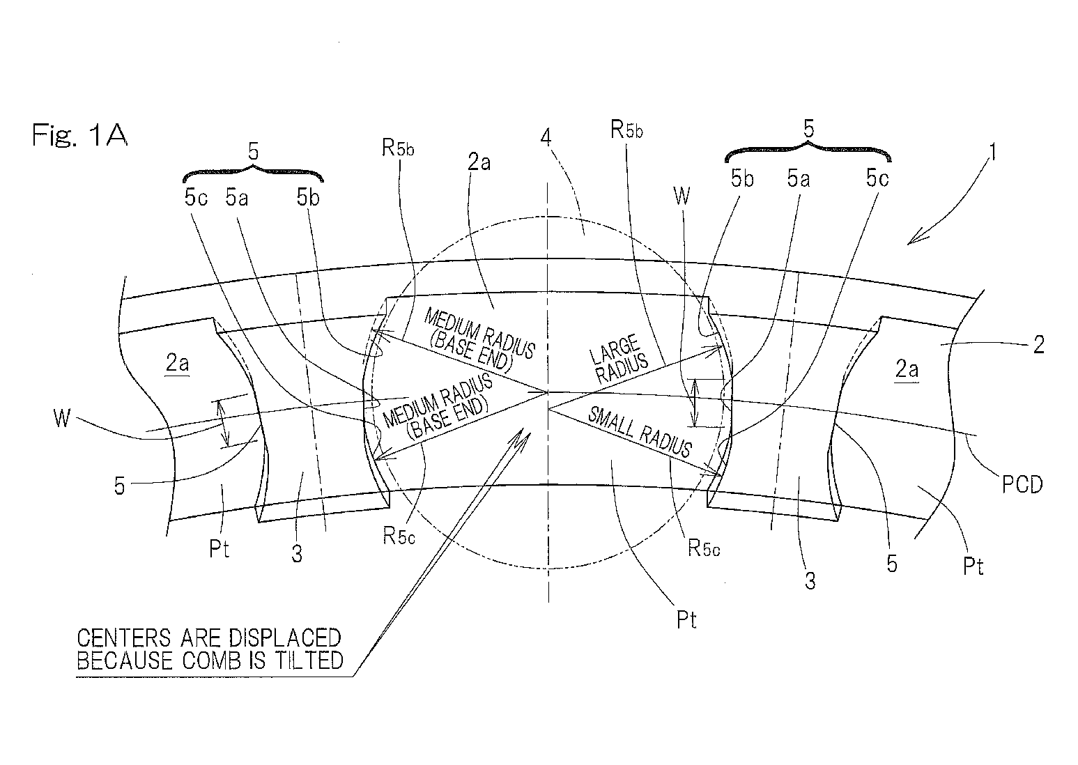
Fig. 1A is a side view of an essential portion of a comb-shaped resin retainer according to a first embodiment and a second embodiment of the present invention; -
Fig. 1B is a front view of the essential portion of the comb-shaped resin retainer; -
Fig. 2 is a perspective view of the essential portion of the comb-shaped resin retainer; -
Fig. 3 is a longitudinal cross-sectional view of a double row cylindrical roller bearing which uses the comb-shaped resin retainer according to any of the precedent embodiments; -
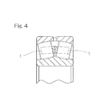
Fig. 4 is a longitudinal cross-sectional view of a self-aligning roller bearing which uses the comb-shaped resin retainer according to any of the above-described embodiments; -
Fig. 5A is a side view of the essential portion of a comb-shaped resin retainer of a comparative example; -
Fig. 5B is a front view of the essential portion of the comb-shaped resin retainer; -
Fig. 6A is a side view of the essential portion of a comb-shaped resin retainer of a conventional example; and -
Fig. 6B is a front view of the essential portion of the comb-shaped resin retainer. - A first embodiment of the present invention will be described in conjunction with
Figs. 1A ,1B , and2 . A comb-shaped resin retainer according to this embodiment is applied to, for example, a double row cylindrical roller bearing which supports the main shaft of a machine tool, such as a CNC lathe, a machining center, a milling machine, a general-purpose lathe, and a boring machine. However, this comb-shaped resin retainer is not limited to the use of supporting the main shaft of the machine tool. Additionally, the comb-shaped resin retainer may be applied to a bearing other than the double row cylindrical roller bearing. - As shown in
Figs. 1A and1B , a comb-shapedresin retainer 1 includes anannular section 2 and a plurality ofpillar sections 3 which protrude to one side in the axial direction from one side face of theannular section 2. Theannular section 2 and thepillar sections 3 are integrally formed by injection molding with, for example, synthetic resin. The plurality ofpillar sections 3 are provided at theannular section 2 at certain intervals in a circumferential direction. A gap between thepillar sections cylindrical roller 4. Each of the pockets Pt is surrounded by oneside face 2a of theannular section 2 and side faces 5, 5, of the circumferentially-adjacent pillar sections resin retainer 1 has a comb-teeth shape which opens to one side in the axial direction. The side face 5 of thepillar section 3 which serves as an inner face of the pocket Pt is formed in a recessed shape in a cross section perpendicular to the retainer axial center. - For example, synthetic resin having self-lubricity, such as polyetheretherketone resin, polyamide resin, or polyphenylene sulfide resin is used as the synthetic resin. However, the synthetic resin is not limited to these synthetic resins. A filling material, such as carbon fiber or glass fiber may be combined with any of the above-described synthetic resin.
- Each of the
pillar sections 3 is tilted so as to become closer to the retainer axial center as thepillar section 3 extends toward the tip thereof. It is to be noted that in the illustrated example, an inner diametric peripheral surface of theannular section 2 and an outer diametric peripheral surface thereof are also tilted in the same manner as thepillar section 3, and that these peripheral surfaces continue so as to form the same cylindrical faces on an inner diametric peripheral surface of thepillar section 3 and an outer diametric side face thereof. An inclination angle α of thepillar section 3 varies dependent on resin materials, a shape of the retainer, and molding conditions. When these conditions are limited within a normal range, the inclination angle α is set, for example, between 5 degrees and 8 degrees. - A "flat portion" 5a is provided on the
side face 5 of thepillar section 3 which serves as a portion of an inner face for the pocket Pt. This "flat portion" 5a refers to a portion in a cross section of thepillar section 3 perpendicular to the retainer axial center and seen in the axial direction. As shown inFigs. 1A and2 , theflat portion 5a is formed linearly. Theflat portion 5a of thepillar section 3 is provided in the vicinity of a pitch circle diameter (PCD) of thecylindrical roller 4. The vicinity of the PCD in this example also includes a region just on the PCD. Thisflat portion 5a continues axially from a tip portion of thepillar section 3 to the base end portion thereof. Moreover, theflat portions flat portion 5a exists may be called "a flat area". - As illustrated in
Fig. 1B , when the side face of thepillar section 3, which serves as the inner face of the pocket Pt, is seen from the inner face side of the pocket Pt, the above-described flat area is a rectangular area surrounded by two sides L1, L2 which are parallel to each other in the inclination direction of thepillar section 3, one side L3 which forms a portion of a tip edge of thepillar section 3, and one side L4 which forms a portion of one side face of theannular section 2. - As shown in
Figs. 1A and2 , an outer diametric side recessedportion 5b and an inner diametric side recessedportion 5c are provided on the side face of thepillar section 3 to serve, together with theflat portion 5a, as the inner face of the pocket Pt. The outer diametric side recessedportion 5b and the inner diametric side recessedportion 5c refer to portions in a cross section of thepillar section 3 perpendicular to the retainer axial center and seen in the axial direction. The outer diametric side recessedportion 5b continues from the outer diametric side edge of theflat portion 5a to the outer diametric side, with theflat portion 5a as the boundary, to form a portion of recessed side face of thepillar section 3 which serves as the inner face of the pocket Pt. The outer diametric side recessedportion 5b is set to have a predetermined radius of curvature R5b. - The inner diametric side recessed
portion 5c continues from the inner diametric side edge of theflat portion 5a to the inner diametric side, with theflat portion 5a as the boundary, to form a portion of recessed side face of thepillar section 3 which serves as the inner face of the pocket Pt is recessed. The inner diametric side recessedportion 5c is set to have a predetermined radius of curvature R5c. Here, the radius of curvature R5b of the outer diametric side recessedportion 5b is set larger than the radius of curvature R5c of the inner diametric side recessedportion 5c. - It is preferable that a radial width W of the
flat portion 5a corresponds to the inclination angle α of thepillar section 3. As mentioned above, theflat portion 5a of thepillar section 3 is disposed in the vicinity of the PCD. When the radial width of theflat portion 5a of thepillar section 3 is represented by W, an inclination angle of thepillar section 3 relative to the retainer axial center is represented by α, and an axial length of theflat portion 5a is represented by L, it is preferable that theflat portion 5a satisfies the following relationship (1). Here, the width W is a widthwise dimension at an arbitrary axial position of the pillar section 3:
- When the axial length of the
pillar section 3 becomes long, the necessary axial length L of theflat portion 5a also becomes long. Further, the angle of thepillar section 3 subjected to molding shrinkage is determined, the width W to be needed is determined. As described before, the angle α of thepillar section 3 varies depending on resin materials, the shape of a retainer, and molding conditions. By providing theflat portion 5a which satisfies the aforementioned relationship (1), the width W of theflat portion 5a can be set in accordance with the angle α of thepillar section 3. Even if any resin material, any shape of a retainer, or any molding condition is set, the value of the necessary width W can be easily obtained from the above relationship (1). - In accordance with the comb-shaped
resin retainer 1 described above, in the comb-shaped resin retainer in which theside face 5 of thepillar section 3 which serves as the inner face of the pocket Pt is formed in a recessed shape, theflat portion 5a is provided on theside face 5 of thepillar section 3 which serves as the inner face of the pocket Pt. Thus, the maximum width of the pocket Pt can be measured at any axial position of thepillar section 3. The position at which the maximum width of the pocket Pt can be measured is shown by hatching inFig. 1B . The above-describedflat portion 5a continues axially from the tip portion of thepillar section 3 to the base end portion thereof. Accordingly, even when any pocket width of thepillar section 3 is measured at any axial position of thepillar section 3 from the tip portion of thepillar section 3 to the base end portion thereof, by measuring theflat portion 5a, the pocket width can be controlled accurately. Hence the pocket width and the gap of theroller 4 can be set so as not to change in the axial direction. Consequently, a uniform contact between theroller 4 and theretainer 1 can easily be obtained. - Furthermore, since each of the
pillar sections 3 is tilted so as to become closer to the retainer axial center as thepillar section 3 extends toward the tip, the amount of movement of theroller 4 is not increased by the influence of centrifugal force, and the strong contact between theroller 4 and theretainer 1 can be prevented. As a result, the wear of theretainer 1 can be reduced. Also, because it is not necessary to carry out mold-adjustment of the comb-shapedresin retainer 1 multiple times, the manufacturing cost thereof can be reduced. - As described above, the
flat portion 5a is provided in the vicinity of the pitch circle diameter. The outer diametric side recessedportion 5b continues from the outer diametric side edge of theflat portion 5a to the outer diametric side to form a portion of recessed side face of thepillar section 3 which serves as the inner face of the pocket Pt. The inner diametric side recessedportion 5c continues from the inner diametric side edge of theflat portion 5a to the inner diametric side to form a portion of recessed side face of thepillar section 3 which serves as the inner face of the pocket Pt. The radius of curvature R5b of the outer diametric side recessedportion 5b is set larger than the radius of curvature R5c of the inner diametric side recessedportion 5c. As a result, the following effects are performed. - Even if each of the
pillar sections 3 is tilted relative to the retainer axial center, the contact between theroller 4 and theretainer 1 is not radially offset. In this way, generation of the partial wear of theretainer 1 can be reduced. It is to be noted that in a comparative example illustrated inFigs. 5A and5B , eachpillar section 3 is tilted as described above and has no flat portion and that the radius of curvature of a pocket Pt is uniform. In this case, because of no flat portion, a pocket measurement position at the tip portion of thepillar section 3 does not represent the maximum width of the pocket. Since the radius of curvature is uniform, the contact between theroller 4 and the retainer occurs only on the outer diametric side of the tip portion of the pillar section 3 (a location denoted by hatching inFig. 5B ). - As a second embodiment of the present invention, in the comb-shaped resin retainer shown in
Fig. 1A , any one or both of the radius of curvature R5b of the outer diametric side recessedportion 5b and the radius of curvature R5c of the inner diametric side recessedportion 5c may be gradually changed from the base end portion of thepillar section 3 to the tip portion thereof. By increasing the radius of curvature of the an inner diametric side recessedportion 5c gradually from the base end portion to the tip portion thereof, the gap between theroller 4 and theretainer 1 can be set large on the tip portion side of the inner diametric side pocket and set small on the base end side thereof. By so changing, the pocket gap (in the radial direction) due to the deformation of thepillar section 3 during a high speed operation can be reduced equally on the tip portion and the base end portion. In this case, even if each of thepillar sections 3 is tilted relative to the retainer axial center, the contact between theroller 4 and theretainer 1 is not offset. Accordingly, generation of the partial wear of theretainer 1 can be reduced. -
Fig. 3 is a longitudinal cross-sectional view of a double row cylindrical roller bearing which uses the comb-shaped resin retainer according to any of the above-described embodiments. The double row cylindrical roller bearing has aninner ring 6, anouter ring 7, and double rowcylindrical rollers 4 which are provided between araceway surface 6a of theinner ring 6 and araceway surface 7a of theouter ring 7, and a pair of comb-shapedresin retainers cylindrical rollers 4. Theinner ring 6 has doublerow raceway surfaces inner rib 8 is provided at an axial center portion of theinner ring 6 andouter ribs - In the pair of comb-shaped
resin retainers annular sections pillar sections 3 are disposed so that each of thepillar sections 3 protrudes from theannular section 2 of the comb-shapedresin retainer 1 toward the axial outer side. In this way, in the respective comb-shapedresin retainers 1, thecylindrical roller 4 is retained in the pocket Pt which opens from the axial center portion of the comb-shapedresin retainer 1 to the axial outer side thereof. Consequently, the comb-shapedresin retainer 1 can be prevented from falling off from the bearing. In addition, in the pair of comb-shapedresin retainers resin retainers - For example, the
inner ring 6 is fit to the outer circumferential surface of a main shaft of a machine tool and theouter ring 7 is fit to the inner circumferential surface of a housing. In the example shown inFig. 3 , an inner ring innercircumferential surface 6b is formed in a cylindrical hole. However, the inner ring innercircumferential surface 6b may be formed in a tapered hole so as to be able to adjust a radial inner gap of the bearing. Grease lubrication, air-oil lubrication, or the like can be used as lubrication of the bearing. - In accordance with this double row cylindrical roller bearing, since the comb-shaped
resin retainer 1 according to any one of the embodiments is used, the amount of movement of theroller 4 is stabilized, the wear of theretainer 1 is reduced, and the manufacturing cost thereof can be reduced. In particular, theflat portion 5a of the comb-shapedresin retainer 1 continues axially from the tip portion of thepillar section 3 to the base end portion thereof. Accordingly, even when any pocket width of thepillar section 3 is measured at any axial position of thepillar section 3 from the tip portion of thepillar section 3 to the base end portion thereof, by measuring theflat portion 5a, the pocket width can be controlled accurately. Since the pocket width and the gap of theroller 4 can be set so as not to change in the axial direction, a uniform contact between theroller 4 and theretainer 1 can easily occur. Accordingly, a high speed operation and a long servicing life of the bearing can be realized. - The comb-shaped resin retainer of any of the above-described embodiments may be applied to a single row cylindrical roller bearing. As illustrated in
Fig. 4 , the above comb-shapedresin retainer 1 can be used for a self-aligning roller bearing. A cylindrical rolling bearing or a self-aligning roller bearing using the above comb-shaped resin retainer can be applied, for example, to a purpose of supporting each shaft of a robot, a conveying device, a transportation machine, or the like. - Although the present invention has been fully described in connection with the preferred embodiments thereof with reference to the accompanying drawings which are used only for the purpose of illustration, those skilled in the art will readily conceive various changes and modifications within the framework of obviousness upon reading of the specification herein presented of the present invention. Accordingly, such changes and modifications are, unless they depart from the scope of the present invention as delivered from the claims annexed hereto, to be construed as included therein.
-
- 1 comb-shaped resin retainer
- 2 annular section
- 3 pillar section
- 4 cylindrical roller
- 5 side face
- 5a flat portion
- 5b outer diametric side recessed portion
- 5c inner diametric side recessed portion
- Pt pocket
Claims (9)
- A comb-shaped resin retainer comprising:an annular section; and a plurality of pillar sections which protrude to one side in an axial direction from one side face of the annular section,wherein a gap between the pillar sections adjacent to each other in a circumferential direction serves as a pocket for retaining a roller, and a side face of the pillar section, which serves as an inner face of the pocket, is formed in a recessed shape,wherein each of the pillar sections is tilted so as to become closer to a retainer axial center as the pillar section extends toward a tip of the pillar section, and a flat portion is provided on the side face of the pillar section which serves as the inner face of the pocket, and the flat portion continues axially from a tip portion of the pillar section toward a base end portion thereof, and the opposing flat portions of the pillar sections are in parallel to each other.
- The comb-shaped resin retainer according to claim 1, wherein the roller is a cylindrical roller.
- The comb-shaped resin retainer according to claim 1, wherein when a radial width of the flat portion of the pillar section is represented by W, an inclination angle of the pillar section relative to the retainer axial center is represented by α, and an axial length of the flat portion is represented by L, the flat portion has a following relationship:

- The comb-shaped resin retainer according to claim 1, wherein the flat portion of the pillar section is provided in a vicinity of a pitch circle diameter of the roller.
- The comb-shaped resin retainer according to claim 4, wherein on the side face of the pillar section which serves as the inner face of the pocket, an outer diametric side recessed portion and an inner diametric side recessed portion are provided with the flat portion therebetween, and the outer diametric side recessed portion continues from an outer diametric side edge of the flat portion to an outer diametric side to form a portion of recessed side face of the pillar section which serves as the inner face of the pocket, while the inner diametric side recessed portion continues from an inner diametric side edge of the flat portion to an inner diametric side to form another portion of recessed side face of the pillar section which serves as the inner face of the pocket, and
wherein a radius of curvature of the outer diametric side recessed portion is set larger than a radius of curvature of the inner diametric side recessed portion. - The comb-shaped resin retainer according to claim 5, wherein any one or both of the radius of curvature of the outer diametric side recessed portion and the radius of curvature of the inner diametric side recessed portion is/are changed gradually from the base end portion of the pillar section to the tip portion thereof.
- A double row cylindrical roller bearing comprising the comb-shaped resin retainer claimed in claim 1.
- The double row cylindrical roller bearing according to claim 7, wherein the double row cylindrical roller bearing is used as a bearing for a main shaft of a machine tool.
- A self-aligning roller bearing comprising the comb-shaped resin retainer claimed in claim 1.
Applications Claiming Priority (2)
| Application Number | Priority Date | Filing Date | Title |
|---|---|---|---|
| JP2010251418A JP5619574B2 (en) | 2010-11-10 | 2010-11-10 | Comb type resin cage and roller bearing |
| PCT/JP2011/075263 WO2012063694A1 (en) | 2010-11-10 | 2011-11-02 | Comb-shaped resin retainer and roller bearing |
Publications (3)
| Publication Number | Publication Date |
|---|---|
| EP2639466A1 true EP2639466A1 (en) | 2013-09-18 |
| EP2639466A4 EP2639466A4 (en) | 2016-11-02 |
| EP2639466B1 EP2639466B1 (en) | 2019-07-24 |
Family
ID=46050844
Family Applications (1)
| Application Number | Title | Priority Date | Filing Date |
|---|---|---|---|
| EP11839447.7A Active EP2639466B1 (en) | 2010-11-10 | 2011-11-02 | Comb-shaped resin retainer and roller bearing |
Country Status (6)
| Country | Link |
|---|---|
| US (1) | US8641291B2 (en) |
| EP (1) | EP2639466B1 (en) |
| JP (1) | JP5619574B2 (en) |
| KR (1) | KR101859599B1 (en) |
| CN (1) | CN103210223B (en) |
| WO (1) | WO2012063694A1 (en) |
Families Citing this family (11)
| Publication number | Priority date | Publication date | Assignee | Title |
|---|---|---|---|---|
| CN102089541B (en) * | 2008-07-08 | 2014-03-05 | 日本精工株式会社 | Resin retainer for tapered roller bearing, and tapered roller bearing |
| JP6131684B2 (en) | 2013-04-03 | 2017-05-24 | 株式会社ジェイテクト | Comb cage for double row roller bearing and double row roller bearing |
| JP6155775B2 (en) | 2013-04-03 | 2017-07-05 | 株式会社ジェイテクト | Resin comb cage and double row roller bearing for double row roller bearing |
| US20140301689A1 (en) | 2013-04-03 | 2014-10-09 | JText Corporation | Prong type cage for double row roller bearing and double row roller bearing |
| DE102014205814B4 (en) * | 2014-03-28 | 2019-06-19 | Aktiebolaget Skf | A method of manufacturing a comb portion of a cage, a method of creating control data for a machine tool for producing a comb portion of a cage, program and cage |
| US9829038B2 (en) * | 2015-04-09 | 2017-11-28 | Aktiebolaget Skf | Bearing and bearing arrangement |
| CN104912921B (en) * | 2015-05-30 | 2017-05-31 | 德清恒富机械有限公司 | Roller bearing |
| US10001169B2 (en) * | 2016-10-25 | 2018-06-19 | Schaeffler Technologies AG & Co. KG | Prong type cage for a double row roller bearing assembly |
| DE202019101921U1 (en) * | 2019-04-03 | 2020-07-06 | Paul Müller GmbH & Co. KG Unternehmensbeteiligungen | Cage-less rolling bearing |
| KR102920456B1 (en) | 2020-05-26 | 2026-01-29 | 섀플러 테크놀로지스 아게 운트 코. 카게 | A Cage For Spherical Roller Bearing |
| JP6781920B1 (en) * | 2020-07-22 | 2020-11-11 | 泰一 岡田 | bearing |
Family Cites Families (12)
| Publication number | Priority date | Publication date | Assignee | Title |
|---|---|---|---|---|
| JPS4320807B1 (en) | 1964-07-18 | 1968-09-06 | ||
| DE3841629C2 (en) * | 1988-12-10 | 1996-07-11 | Skf Gmbh | Roller bearings |
| GB2365934B (en) * | 1997-10-01 | 2002-04-10 | Nsk Ltd | Synthetic resin cage for roller bearing |
| JP2005098521A (en) | 1997-10-01 | 2005-04-14 | Nsk Ltd | Synthetic resin cage and roller bearing for roller bearings |
| JP3877004B2 (en) * | 2001-09-10 | 2007-02-07 | 日本精工株式会社 | Double row cylindrical roller bearing |
| JP4115940B2 (en) * | 2001-09-10 | 2008-07-09 | 日本精工株式会社 | Double row cylindrical roller bearing |
| JP4537920B2 (en) | 2005-09-15 | 2010-09-08 | Ntn株式会社 | Resin retainer, resin retainer mold and resin retainer manufacturing method |
| JP2007278406A (en) * | 2006-04-07 | 2007-10-25 | Nsk Ltd | Roller bearing with cage |
| JPWO2007139197A1 (en) * | 2006-05-31 | 2009-10-15 | 日本精工株式会社 | Rolling device |
| JP4636035B2 (en) * | 2007-02-22 | 2011-02-23 | 日本精工株式会社 | Rolling bearing |
| JP2009068592A (en) * | 2007-09-13 | 2009-04-02 | Nsk Ltd | Spherical roller bearing with cage and manufacturing method of cage for spherical roller bearing |
| JP2009085257A (en) * | 2007-09-28 | 2009-04-23 | Nsk Ltd | Spherical roller bearing cage |
-
2010
- 2010-11-10 JP JP2010251418A patent/JP5619574B2/en active Active
-
2011
- 2011-11-02 KR KR1020137010600A patent/KR101859599B1/en active Active
- 2011-11-02 CN CN201180053732.1A patent/CN103210223B/en active Active
- 2011-11-02 WO PCT/JP2011/075263 patent/WO2012063694A1/en not_active Ceased
- 2011-11-02 EP EP11839447.7A patent/EP2639466B1/en active Active
- 2011-11-02 US US13/883,724 patent/US8641291B2/en active Active
Also Published As
| Publication number | Publication date |
|---|---|
| US20130223785A1 (en) | 2013-08-29 |
| EP2639466A4 (en) | 2016-11-02 |
| EP2639466B1 (en) | 2019-07-24 |
| US8641291B2 (en) | 2014-02-04 |
| CN103210223B (en) | 2015-10-07 |
| WO2012063694A1 (en) | 2012-05-18 |
| KR20130139947A (en) | 2013-12-23 |
| KR101859599B1 (en) | 2018-05-18 |
| JP5619574B2 (en) | 2014-11-05 |
| CN103210223A (en) | 2013-07-17 |
| JP2012102796A (en) | 2012-05-31 |
Similar Documents
| Publication | Publication Date | Title |
|---|---|---|
| EP2639466B1 (en) | Comb-shaped resin retainer and roller bearing | |
| JP6508196B2 (en) | Angular contact ball bearings | |
| CN104100640B (en) | The resin prong-shaped cage and double-row roller bearing of double-row roller bearing | |
| KR101960144B1 (en) | Angular ball bearing | |
| EP3385552B1 (en) | Self-aligning roller bearing | |
| US7594761B2 (en) | Cylindrical roller bearing and cage for cylindrical roller bearings | |
| US20050069239A1 (en) | Cylindrical roller bearing | |
| EP1947356A2 (en) | Cage for rolling bearing and rolling bearing having the same | |
| EP2876320A1 (en) | Split Cage And Roller Bearing | |
| US11248656B2 (en) | Cage and roller assembly | |
| US10655678B2 (en) | Cage and roller assembly | |
| US9453534B2 (en) | Tapered roller bearing | |
| US10167897B2 (en) | Tapered roller bearing | |
| US10663001B2 (en) | Ball bearing cage | |
| JP2009275722A (en) | Rolling bearing | |
| US10634191B2 (en) | Cage and roller assembly | |
| JP5757819B2 (en) | Segment cage for rolling bearings | |
| JP4537920B2 (en) | Resin retainer, resin retainer mold and resin retainer manufacturing method | |
| US10197094B2 (en) | Double-row spherical roller bearing | |
| JP2011069460A (en) | Roller bearing and cage for roller bearing | |
| EP3540250A1 (en) | Resin holder for cylindrical roller bearings and cylindrical roller bearing | |
| JP2008008370A (en) | Cylindrical roller bearing cage |
Legal Events
| Date | Code | Title | Description |
|---|---|---|---|
| PUAI | Public reference made under article 153(3) epc to a published international application that has entered the european phase |
Free format text: ORIGINAL CODE: 0009012 |
|
| 17P | Request for examination filed |
Effective date: 20130517 |
|
| AK | Designated contracting states |
Kind code of ref document: A1 Designated state(s): AL AT BE BG CH CY CZ DE DK EE ES FI FR GB GR HR HU IE IS IT LI LT LU LV MC MK MT NL NO PL PT RO RS SE SI SK SM TR |
|
| DAX | Request for extension of the european patent (deleted) | ||
| RA4 | Supplementary search report drawn up and despatched (corrected) |
Effective date: 20161006 |
|
| RIC1 | Information provided on ipc code assigned before grant |
Ipc: F16C 19/28 20060101ALI20160929BHEP Ipc: F16C 33/49 20060101AFI20160929BHEP |
|
| STAA | Information on the status of an ep patent application or granted ep patent |
Free format text: STATUS: EXAMINATION IS IN PROGRESS |
|
| 17Q | First examination report despatched |
Effective date: 20181012 |
|
| GRAP | Despatch of communication of intention to grant a patent |
Free format text: ORIGINAL CODE: EPIDOSNIGR1 |
|
| STAA | Information on the status of an ep patent application or granted ep patent |
Free format text: STATUS: GRANT OF PATENT IS INTENDED |
|
| INTG | Intention to grant announced |
Effective date: 20190225 |
|
| GRAS | Grant fee paid |
Free format text: ORIGINAL CODE: EPIDOSNIGR3 |
|
| GRAA | (expected) grant |
Free format text: ORIGINAL CODE: 0009210 |
|
| STAA | Information on the status of an ep patent application or granted ep patent |
Free format text: STATUS: THE PATENT HAS BEEN GRANTED |
|
| AK | Designated contracting states |
Kind code of ref document: B1 Designated state(s): AL AT BE BG CH CY CZ DE DK EE ES FI FR GB GR HR HU IE IS IT LI LT LU LV MC MK MT NL NO PL PT RO RS SE SI SK SM TR |
|
| REG | Reference to a national code |
Ref country code: GB Ref legal event code: FG4D |
|
| REG | Reference to a national code |
Ref country code: CH Ref legal event code: EP |
|
| REG | Reference to a national code |
Ref country code: DE Ref legal event code: R096 Ref document number: 602011060778 Country of ref document: DE |
|
| REG | Reference to a national code |
Ref country code: AT Ref legal event code: REF Ref document number: 1158533 Country of ref document: AT Kind code of ref document: T Effective date: 20190815 |
|
| REG | Reference to a national code |
Ref country code: IE Ref legal event code: FG4D |
|
| REG | Reference to a national code |
Ref country code: NL Ref legal event code: MP Effective date: 20190724 |
|
| REG | Reference to a national code |
Ref country code: LT Ref legal event code: MG4D |
|
| REG | Reference to a national code |
Ref country code: AT Ref legal event code: MK05 Ref document number: 1158533 Country of ref document: AT Kind code of ref document: T Effective date: 20190724 |
|
| PG25 | Lapsed in a contracting state [announced via postgrant information from national office to epo] |
Ref country code: NO Free format text: LAPSE BECAUSE OF FAILURE TO SUBMIT A TRANSLATION OF THE DESCRIPTION OR TO PAY THE FEE WITHIN THE PRESCRIBED TIME-LIMIT Effective date: 20191024 Ref country code: HR Free format text: LAPSE BECAUSE OF FAILURE TO SUBMIT A TRANSLATION OF THE DESCRIPTION OR TO PAY THE FEE WITHIN THE PRESCRIBED TIME-LIMIT Effective date: 20190724 Ref country code: SE Free format text: LAPSE BECAUSE OF FAILURE TO SUBMIT A TRANSLATION OF THE DESCRIPTION OR TO PAY THE FEE WITHIN THE PRESCRIBED TIME-LIMIT Effective date: 20190724 Ref country code: FI Free format text: LAPSE BECAUSE OF FAILURE TO SUBMIT A TRANSLATION OF THE DESCRIPTION OR TO PAY THE FEE WITHIN THE PRESCRIBED TIME-LIMIT Effective date: 20190724 Ref country code: PT Free format text: LAPSE BECAUSE OF FAILURE TO SUBMIT A TRANSLATION OF THE DESCRIPTION OR TO PAY THE FEE WITHIN THE PRESCRIBED TIME-LIMIT Effective date: 20191125 Ref country code: NL Free format text: LAPSE BECAUSE OF FAILURE TO SUBMIT A TRANSLATION OF THE DESCRIPTION OR TO PAY THE FEE WITHIN THE PRESCRIBED TIME-LIMIT Effective date: 20190724 Ref country code: AT Free format text: LAPSE BECAUSE OF FAILURE TO SUBMIT A TRANSLATION OF THE DESCRIPTION OR TO PAY THE FEE WITHIN THE PRESCRIBED TIME-LIMIT Effective date: 20190724 Ref country code: LT Free format text: LAPSE BECAUSE OF FAILURE TO SUBMIT A TRANSLATION OF THE DESCRIPTION OR TO PAY THE FEE WITHIN THE PRESCRIBED TIME-LIMIT Effective date: 20190724 Ref country code: BG Free format text: LAPSE BECAUSE OF FAILURE TO SUBMIT A TRANSLATION OF THE DESCRIPTION OR TO PAY THE FEE WITHIN THE PRESCRIBED TIME-LIMIT Effective date: 20191024 |
|
| PG25 | Lapsed in a contracting state [announced via postgrant information from national office to epo] |
Ref country code: AL Free format text: LAPSE BECAUSE OF FAILURE TO SUBMIT A TRANSLATION OF THE DESCRIPTION OR TO PAY THE FEE WITHIN THE PRESCRIBED TIME-LIMIT Effective date: 20190724 Ref country code: ES Free format text: LAPSE BECAUSE OF FAILURE TO SUBMIT A TRANSLATION OF THE DESCRIPTION OR TO PAY THE FEE WITHIN THE PRESCRIBED TIME-LIMIT Effective date: 20190724 Ref country code: GR Free format text: LAPSE BECAUSE OF FAILURE TO SUBMIT A TRANSLATION OF THE DESCRIPTION OR TO PAY THE FEE WITHIN THE PRESCRIBED TIME-LIMIT Effective date: 20191025 Ref country code: LV Free format text: LAPSE BECAUSE OF FAILURE TO SUBMIT A TRANSLATION OF THE DESCRIPTION OR TO PAY THE FEE WITHIN THE PRESCRIBED TIME-LIMIT Effective date: 20190724 Ref country code: RS Free format text: LAPSE BECAUSE OF FAILURE TO SUBMIT A TRANSLATION OF THE DESCRIPTION OR TO PAY THE FEE WITHIN THE PRESCRIBED TIME-LIMIT Effective date: 20190724 Ref country code: IS Free format text: LAPSE BECAUSE OF FAILURE TO SUBMIT A TRANSLATION OF THE DESCRIPTION OR TO PAY THE FEE WITHIN THE PRESCRIBED TIME-LIMIT Effective date: 20191124 |
|
| PG25 | Lapsed in a contracting state [announced via postgrant information from national office to epo] |
Ref country code: TR Free format text: LAPSE BECAUSE OF FAILURE TO SUBMIT A TRANSLATION OF THE DESCRIPTION OR TO PAY THE FEE WITHIN THE PRESCRIBED TIME-LIMIT Effective date: 20190724 |
|
| PG25 | Lapsed in a contracting state [announced via postgrant information from national office to epo] |
Ref country code: RO Free format text: LAPSE BECAUSE OF FAILURE TO SUBMIT A TRANSLATION OF THE DESCRIPTION OR TO PAY THE FEE WITHIN THE PRESCRIBED TIME-LIMIT Effective date: 20190724 Ref country code: EE Free format text: LAPSE BECAUSE OF FAILURE TO SUBMIT A TRANSLATION OF THE DESCRIPTION OR TO PAY THE FEE WITHIN THE PRESCRIBED TIME-LIMIT Effective date: 20190724 Ref country code: PL Free format text: LAPSE BECAUSE OF FAILURE TO SUBMIT A TRANSLATION OF THE DESCRIPTION OR TO PAY THE FEE WITHIN THE PRESCRIBED TIME-LIMIT Effective date: 20190724 Ref country code: DK Free format text: LAPSE BECAUSE OF FAILURE TO SUBMIT A TRANSLATION OF THE DESCRIPTION OR TO PAY THE FEE WITHIN THE PRESCRIBED TIME-LIMIT Effective date: 20190724 |
|
| PG25 | Lapsed in a contracting state [announced via postgrant information from national office to epo] |
Ref country code: CZ Free format text: LAPSE BECAUSE OF FAILURE TO SUBMIT A TRANSLATION OF THE DESCRIPTION OR TO PAY THE FEE WITHIN THE PRESCRIBED TIME-LIMIT Effective date: 20190724 Ref country code: SM Free format text: LAPSE BECAUSE OF FAILURE TO SUBMIT A TRANSLATION OF THE DESCRIPTION OR TO PAY THE FEE WITHIN THE PRESCRIBED TIME-LIMIT Effective date: 20190724 Ref country code: SK Free format text: LAPSE BECAUSE OF FAILURE TO SUBMIT A TRANSLATION OF THE DESCRIPTION OR TO PAY THE FEE WITHIN THE PRESCRIBED TIME-LIMIT Effective date: 20190724 Ref country code: IS Free format text: LAPSE BECAUSE OF FAILURE TO SUBMIT A TRANSLATION OF THE DESCRIPTION OR TO PAY THE FEE WITHIN THE PRESCRIBED TIME-LIMIT Effective date: 20200224 |
|
| REG | Reference to a national code |
Ref country code: DE Ref legal event code: R097 Ref document number: 602011060778 Country of ref document: DE |
|
| REG | Reference to a national code |
Ref country code: CH Ref legal event code: PL |
|
| PLBE | No opposition filed within time limit |
Free format text: ORIGINAL CODE: 0009261 |
|
| STAA | Information on the status of an ep patent application or granted ep patent |
Free format text: STATUS: NO OPPOSITION FILED WITHIN TIME LIMIT |
|
| PG2D | Information on lapse in contracting state deleted |
Ref country code: IS |
|
| PG25 | Lapsed in a contracting state [announced via postgrant information from national office to epo] |
Ref country code: LU Free format text: LAPSE BECAUSE OF NON-PAYMENT OF DUE FEES Effective date: 20191102 Ref country code: MC Free format text: LAPSE BECAUSE OF FAILURE TO SUBMIT A TRANSLATION OF THE DESCRIPTION OR TO PAY THE FEE WITHIN THE PRESCRIBED TIME-LIMIT Effective date: 20190724 Ref country code: LI Free format text: LAPSE BECAUSE OF NON-PAYMENT OF DUE FEES Effective date: 20191130 Ref country code: CH Free format text: LAPSE BECAUSE OF NON-PAYMENT OF DUE FEES Effective date: 20191130 |
|
| 26N | No opposition filed |
Effective date: 20200603 |
|
| REG | Reference to a national code |
Ref country code: BE Ref legal event code: MM Effective date: 20191130 |
|
| PG25 | Lapsed in a contracting state [announced via postgrant information from national office to epo] |
Ref country code: SI Free format text: LAPSE BECAUSE OF FAILURE TO SUBMIT A TRANSLATION OF THE DESCRIPTION OR TO PAY THE FEE WITHIN THE PRESCRIBED TIME-LIMIT Effective date: 20190724 |
|
| GBPC | Gb: european patent ceased through non-payment of renewal fee |
Effective date: 20191102 |
|
| PG25 | Lapsed in a contracting state [announced via postgrant information from national office to epo] |
Ref country code: IE Free format text: LAPSE BECAUSE OF NON-PAYMENT OF DUE FEES Effective date: 20191102 Ref country code: GB Free format text: LAPSE BECAUSE OF NON-PAYMENT OF DUE FEES Effective date: 20191102 Ref country code: FR Free format text: LAPSE BECAUSE OF NON-PAYMENT OF DUE FEES Effective date: 20191130 |
|
| PG25 | Lapsed in a contracting state [announced via postgrant information from national office to epo] |
Ref country code: BE Free format text: LAPSE BECAUSE OF NON-PAYMENT OF DUE FEES Effective date: 20191130 |
|
| PG25 | Lapsed in a contracting state [announced via postgrant information from national office to epo] |
Ref country code: CY Free format text: LAPSE BECAUSE OF FAILURE TO SUBMIT A TRANSLATION OF THE DESCRIPTION OR TO PAY THE FEE WITHIN THE PRESCRIBED TIME-LIMIT Effective date: 20190724 |
|
| PG25 | Lapsed in a contracting state [announced via postgrant information from national office to epo] |
Ref country code: HU Free format text: LAPSE BECAUSE OF FAILURE TO SUBMIT A TRANSLATION OF THE DESCRIPTION OR TO PAY THE FEE WITHIN THE PRESCRIBED TIME-LIMIT; INVALID AB INITIO Effective date: 20111102 Ref country code: MT Free format text: LAPSE BECAUSE OF FAILURE TO SUBMIT A TRANSLATION OF THE DESCRIPTION OR TO PAY THE FEE WITHIN THE PRESCRIBED TIME-LIMIT Effective date: 20190724 |
|
| PG25 | Lapsed in a contracting state [announced via postgrant information from national office to epo] |
Ref country code: MK Free format text: LAPSE BECAUSE OF FAILURE TO SUBMIT A TRANSLATION OF THE DESCRIPTION OR TO PAY THE FEE WITHIN THE PRESCRIBED TIME-LIMIT Effective date: 20190724 |
|
| PGFP | Annual fee paid to national office [announced via postgrant information from national office to epo] |
Ref country code: DE Payment date: 20250930 Year of fee payment: 15 |
|
| PGFP | Annual fee paid to national office [announced via postgrant information from national office to epo] |
Ref country code: IT Payment date: 20251022 Year of fee payment: 15 |