JP2005098521A - Synthetic resin-made retainer for roller bearing and roller bearing - Google Patents

Synthetic resin-made retainer for roller bearing and roller bearing Download PDF

Info

Publication number
JP2005098521A
JP2005098521A JP2005001080A JP2005001080A JP2005098521A JP 2005098521 A JP2005098521 A JP 2005098521A JP 2005001080 A JP2005001080 A JP 2005001080A JP 2005001080 A JP2005001080 A JP 2005001080A JP 2005098521 A JP2005098521 A JP 2005098521A
Authority
JP
Japan
Prior art keywords
synthetic resin
roller bearing
resin cage
column
cage
Prior art date
Legal status (The legal status is an assumption and is not a legal conclusion. Google has not performed a legal analysis and makes no representation as to the accuracy of the status listed.)
Pending
Application number
JP2005001080A
Other languages
Japanese (ja)
Other versions
JP2005098521A5 (en
Inventor
Susumu Takano
晋 高野
Yukio Oura
大浦  行雄
Current Assignee (The listed assignees may be inaccurate. Google has not performed a legal analysis and makes no representation or warranty as to the accuracy of the list.)
NSK Ltd
Original Assignee
NSK Ltd
Priority date (The priority date is an assumption and is not a legal conclusion. Google has not performed a legal analysis and makes no representation as to the accuracy of the date listed.)
Filing date
Publication date
Application filed by NSK Ltd filed Critical NSK Ltd
Priority to JP2005001080A priority Critical patent/JP2005098521A/en
Publication of JP2005098521A publication Critical patent/JP2005098521A/en
Publication of JP2005098521A5 publication Critical patent/JP2005098521A5/ja
Pending legal-status Critical Current

Links

Images

Abstract

<P>PROBLEM TO BE SOLVED: To realize a structure by which a continuous part between each pillar part 4, 4 and an annular part 5 cannot break easily even when a circumferential force is applied from a roller 6, 6 to the pillar part 4, 4. <P>SOLUTION: Only a basis end of each pillar part 4, 4 is made continuous with the annular part 5, and a head is a free end that is not restrained. A connecting frame part 8 extending over the circumference is arranged only between the heads of some of the pillar parts 4, 4. Then falling of the synthetic resin-made retainer 1a is prevented by facing the connecting frame part 8 to an end surface of some of the rollers 6, or by engaging a projection formed at a part of the pillar part 4, 4 with a part of a race ring. <P>COPYRIGHT: (C)2005,JPO&NCIPI

Description

本発明のころ軸受用合成樹脂製保持器は、例えば工作機械の主軸等、微量のグリース又は潤滑油によって潤滑されつつ高速で運転される回転体を支持するころ軸受に組み込む合成樹脂製保持器の改良に関する。特に、本発明のころ軸受用合成樹脂製保持器は、円筒ころ軸受の運転条件や組立状態のばらつきに基づいて、静粛性、寿命等の機能が変動する事を抑制する為に有効である。   The synthetic resin cage for roller bearings of the present invention is a synthetic resin cage incorporated in a roller bearing that supports a rotating body that is operated at high speed while being lubricated by a small amount of grease or lubricating oil, such as a spindle of a machine tool. Regarding improvements. In particular, the synthetic resin cage for roller bearings of the present invention is effective for suppressing fluctuations in functions such as quietness and life based on variations in operating conditions and assembly conditions of cylindrical roller bearings.

工作機械の主軸を回転自在に支持する為の軸受には、工作精度の向上の為、高剛性、高回転精度、低発熱等の特性が求められる。又、近年に於いては、加工効率向上の為、高回転速度で長時間安定して使用できる様に、高速安定性が求められている。この様な各特性のうち、ラジアル方向の剛性を向上させる為に、上記軸受として円筒ころ軸受を使用する場合が多い。又、ラジアル方向の剛性を更に向上させると共に回転精度を向上させる為、円筒ころ軸受の内部隙間を負にする、所謂予圧を付与する事もある。但し、この様な予圧付与を行なう事は、ころ軸受等の転がり軸受にとっては、内部の部品摩耗や焼付き等の故障が発生し易い過酷な条件である。この為に一般の産業機械用の転がり軸受では、運転時に軸受内に正の隙間が残る様にして、剥離寿命の延長を図ると共に、外乱により軸受機能が低下するのを抑える事も多い。又、運転時の発熱を最小にする為、工作機械用の転がり軸受は、ごく微量のグリースや潤滑油等による潤滑条件下で運転される事が多い。即ち、グリースや潤滑油等の潤滑剤を必要最小限に抑える事により、潤滑剤の撹拌抵抗と、この撹拌抵抗に基づく発熱とを抑えている。   Bearings for rotatably supporting the spindle of a machine tool are required to have characteristics such as high rigidity, high rotational accuracy, and low heat generation in order to improve the machining accuracy. In recent years, in order to improve processing efficiency, high-speed stability is required so that it can be used stably for a long time at a high rotational speed. Of these characteristics, in order to improve the rigidity in the radial direction, a cylindrical roller bearing is often used as the bearing. In order to further improve the rigidity in the radial direction and improve the rotational accuracy, a so-called preload may be applied to make the internal gap of the cylindrical roller bearing negative. However, the application of such preload is a severe condition in which a rolling bearing such as a roller bearing is liable to cause a failure such as internal component wear or seizure. For this reason, in general rolling bearings for industrial machines, a positive gap is left in the bearing during operation so as to extend the peeling life and to suppress deterioration of the bearing function due to disturbance. In order to minimize heat generation during operation, rolling bearings for machine tools are often operated under lubrication conditions with a very small amount of grease or lubricating oil. That is, by suppressing the lubricant such as grease and lubricating oil to the minimum necessary, the stirring resistance of the lubricant and the heat generation based on the stirring resistance are suppressed.

上述の様な厳しい使用条件下で、ころ軸受により回転自在に支承した主軸等の回転体の回転速度を更に高める為には、解決しなければならない種々の問題がある。この様な問題の一つとして、従来より上記ころ軸受に標準的に使用されてきた、銅合金製の保持器の摩耗問題がある。即ち、ころ軸受を上述の様な過酷な条件下で使用すると、保持器の内外両周面、或はポケットの内面が、軌道輪の周面やころの表面(転動面及び端面)と強く擦れ合う。この為、軌道輪並びに保持器を構成する軸受鋼等の硬質金属に比べて軟らかい、銅合金製の保持器が摩耗し、この保持器から摩耗粉が発生し易くなる。特に、ころ軸受の潤滑をグリースで行なっている場合、この摩耗粉がグリース中に混入する(グリースを汚染する)事により、このグリースの潤滑性が低下する。そして、潤滑性が著しく低下した場合には、上記ころ軸受が、短時間で焼き付きや著しい摩耗等の損傷を受ける可能性がある。   There are various problems to be solved in order to further increase the rotational speed of a rotating body such as a main shaft that is rotatably supported by a roller bearing under severe conditions as described above. As one of such problems, there is a problem of wear of a copper alloy cage that has been conventionally used for the roller bearing as a standard. In other words, when the roller bearing is used under the severe conditions as described above, both the inner and outer peripheral surfaces of the cage or the inner surface of the pocket are strong against the peripheral surface of the bearing ring and the surface (rolling surface and end surface) of the roller. rub against. For this reason, it is softer than hard metal such as bearing steel and the like constituting the bearing ring and the cage, and the cage made of copper alloy is worn, and wear powder is easily generated from the cage. In particular, when the roller bearing is lubricated with grease, the wear powder is mixed in the grease (contaminates the grease), so that the lubricity of the grease decreases. And when lubricity falls remarkably, the said roller bearing may receive damage, such as seizing and remarkable abrasion, in a short time.

この様な事情に鑑みて、近年では、工作機械の主軸等、大きな荷重を受ける回転体を回転自在に支持する為のころ軸受に組み込む保持器として、合成樹脂製の保持器を使用する場合が多くなりつつある。この様な合成樹脂製の保持器として通常は、ポリアミド樹脂等、優れた摩擦特性を有する(摩耗しにくい)合成樹脂中に、ガラス繊維等の補強材を適量混入した、繊維強化合成樹脂を射出成形する事により造ったものを使用している。この様な合成樹脂製の保持器を組み込んだころ軸受は、前述の様な過酷な使用条件下でも摩耗粉が発生しにくく、焼き付きや著しい摩耗等の損傷を発生しにくくできる。   In view of such circumstances, in recent years, a cage made of a synthetic resin may be used as a cage incorporated in a roller bearing for rotatably supporting a rotating body that receives a large load such as a spindle of a machine tool. It is increasing. As a cage made of such a synthetic resin, a fiber reinforced synthetic resin in which an appropriate amount of a reinforcing material such as glass fiber is mixed in a synthetic resin having excellent friction characteristics (hard to wear) such as a polyamide resin is usually injected. The one made by molding is used. A roller bearing incorporating such a cage made of synthetic resin is less likely to generate wear powder even under the severe use conditions as described above, and can hardly cause damage such as seizure or significant wear.

ところが、単に工作機械の主軸等、大きな荷重を受ける回転体を回転自在に支持する為のころ軸受に組み込む保持器の材質を、銅合金から合成樹脂に変えただけでは、回転支持部の信頼性及び耐久性を十分に確保できない可能性がある。この理由は、次の通りである。即ち、ガラス繊維強化ポリアミド樹脂等の合成樹脂系材料は、銅合金よりも剛性や破断強度が小さい。この為、従来の銅合金製の保持器と同様な形状では、十分な剛性及び強度を確保する事が難しい。この様な理由で、合成樹脂製保持器の形状及び寸法は、従来の銅合金製保持器よりも、肉厚でしかも大きくなり易い。   However, simply changing the material of the cage built into the roller bearing for rotatably supporting a rotating body that receives a large load, such as the spindle of a machine tool, from copper alloy to synthetic resin, the reliability of the rotating support part In addition, sufficient durability may not be ensured. The reason for this is as follows. That is, a synthetic resin material such as a glass fiber reinforced polyamide resin has smaller rigidity and breaking strength than a copper alloy. For this reason, it is difficult to ensure sufficient rigidity and strength with the same shape as the conventional copper alloy cage. For these reasons, the shape and dimensions of the synthetic resin cage are likely to be thicker and larger than conventional copper alloy cages.

一方、合成樹脂製保持器を射出成形するには成形金型を使用するが、金型の形態は、造るべき保持器の形状によって、ラジアルドロー型又はアキシャルドロー型を使用する。このうちのアキシャルドロー型は、合成樹脂製保持器の軸方向に相対変位する、2つの金型素子により成る。この為、造るべき保持器形状は、1対の金型素子を軸方向に抜ける、即ち、射出成形後の合成樹脂製保持器を傷める事なく、上記1対の金型素子同士を離れさせる事が可能な形状にする必要がある。これに対して、ラジアルドロー型は、合成樹脂製保持器の軸方向に移動する1対の金型素子と、直径方向に移動自在な複数の(一般的にはポケットと同数の)金型素子とより成る。従って、造るべき合成樹脂製保持器の形状は、必ずしも金型素子が軸方向に抜ける様にする必要はない。但し、ラジアルドロー型の場合には、金型の構造が複雑になる為、アキシャルドロー型により造れる合成樹脂製保持器に比べて、製造コストが嵩む事が避けられない。   On the other hand, a molding die is used for injection molding of the synthetic resin cage, and the die shape is a radial draw type or an axial draw type depending on the shape of the cage to be manufactured. Of these, the axial draw type is composed of two mold elements that are relatively displaced in the axial direction of the synthetic resin cage. For this reason, the shape of the cage to be manufactured is that the pair of mold elements are separated from each other without losing the pair of mold elements in the axial direction, that is, without damaging the synthetic resin cage after injection molding. It is necessary to make the shape possible. On the other hand, the radial draw type has a pair of mold elements that move in the axial direction of the synthetic resin cage and a plurality of mold elements that are movable in the diametrical direction (generally the same number as the pockets). It consists of. Therefore, the shape of the synthetic resin cage to be produced does not necessarily have to be such that the mold element can be removed in the axial direction. However, in the case of the radial draw type, since the structure of the mold becomes complicated, it is inevitable that the manufacturing cost increases compared to the synthetic resin cage made by the axial draw type.

ところで、ころ軸受に組み込む合成樹脂製保持器は、互いに間隔をあけて同心且つ平行に配置された、第一、第二の円環部を備える。又、円周方向に亙って互いに等間隔に配置された複数本の柱部の一端部を上記第一の円環部の内側面に、同じく他端部を上記第二の円環部の内側面に、それぞれ連続させている。そして、それぞれが、これら各柱部の円周方向両側面と上記第一、第二の円環部の内側面とにより周囲を囲まれた部分に設けられた複数のポケットの内側に、それぞれころを転動自在に保持自在としている。   By the way, the synthetic resin cage incorporated in the roller bearing includes first and second annular portions arranged concentrically and in parallel with each other. In addition, one end of a plurality of pillars arranged at equal intervals in the circumferential direction is on the inner surface of the first annular part, and the other end is also on the second annular part. Continuing on the inner surface. And each roller is respectively inside the plurality of pockets provided in the portion surrounded by the circumferential side surfaces of each of the pillar portions and the inner surface of the first and second annular portions. Can be held freely.

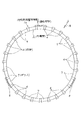
この様なころ軸受用の合成樹脂製保持器をアキシャルドロー型により造る場合、上述した成形加工上の制約により、上記第一の円環部の内径を上記第二の円環部の外径以上にする必要がある。これに対して、上記合成樹脂製保持器をラジアルドロー型により造る場合には、第一、第二の円環部の双方を、同じ寸法及び形状にできる。この様に第一、第二の円環部の寸法及び形状を同じにし、合成樹脂製保持器の形状を軸方向中央部に対して対称にすれば、ころ軸受を高速で運転し、合成樹脂製保持器を高速回転させた場合に、この合成樹脂製保持器の動的バランスを保つ点からは有利であり、耐久性を確保できると考えられていた。この為従来は、工作機械の主軸等、大きな荷重を受ける回転体を回転自在に支持する為のころ軸受に組み込む保持器として、ラジアルドロー型により造った、図31に示す様な、軸方向中央部に関して対称な形状を有する合成樹脂製保持器1を使用していた。   When such a synthetic resin cage for roller bearings is manufactured by an axial draw type, the inner diameter of the first annular portion is larger than the outer diameter of the second annular portion due to the above-described restrictions on the molding process. It is necessary to. On the other hand, in the case where the synthetic resin cage is made by a radial draw type, both the first and second annular portions can be the same size and shape. In this way, if the size and shape of the first and second annular parts are made the same and the shape of the synthetic resin cage is made symmetrical with respect to the central part in the axial direction, the roller bearing can be operated at high speed, and the synthetic resin It was considered that when the cage made of rotation was rotated at high speed, it was advantageous from the viewpoint of maintaining the dynamic balance of the cage made of synthetic resin, and durability could be secured. For this reason, conventionally, as a cage incorporated in a roller bearing for rotatably supporting a rotating body that receives a large load, such as a main shaft of a machine tool, a radial center type as shown in FIG. The synthetic resin cage 1 having a symmetrical shape with respect to the part was used.

上述の様な、軸方向中央部に関して対称な形状を有する合成樹脂製保持器1を円筒ころ軸受に組み込み、この円筒ころ軸受により工作機械の主軸等、大きな荷重を受ける回転体の回転支持部を構成した場合に、必ずしも合成樹脂製保持器1の信頼性及び耐久性を十分に確保できない事が、本発明者の研究により分った。この理由は、次の通りである。   As described above, the synthetic resin cage 1 having a symmetrical shape with respect to the central portion in the axial direction is incorporated in a cylindrical roller bearing, and a rotating support portion of a rotating body that receives a large load, such as a main shaft of a machine tool, is provided by the cylindrical roller bearing. The inventors have found that the reliability and durability of the synthetic resin cage 1 cannot always be sufficiently secured when configured. The reason for this is as follows.

即ち、上記合成樹脂製保持器1を備えたころ軸受を上記回転支持部に対し、正しく組み付ければ良いが、必ずしも正しく組み付けられるとは限らない。例えば、ハウジングと外輪との締め代、或は主軸と内輪との締め代が過大である等、組み込み隙間の調整が不正確な場合には、ころ軸受の内部隙間が負側に大きくずれる可能性がある。又、組立直後に内部隙間が適切であった場合でも、組立後の試運転時にころ軸受が、潤滑用のグリースの撹拌抵抗等で著しく発熱すると、運転時に於けるころ軸受の内部隙間が、負側に大きくずれる可能性がある。   That is, the roller bearing provided with the synthetic resin cage 1 may be correctly assembled to the rotation support portion, but is not necessarily correctly assembled. For example, if the adjustment of the mounting clearance is inaccurate, such as the tightening allowance between the housing and the outer ring, or the tightening allowance between the main shaft and the inner ring, the internal clearance of the roller bearing may be greatly shifted to the negative side. There is. Even if the internal clearance is appropriate immediately after assembly, if the roller bearing generates significant heat due to the agitation resistance of the lubricating grease during the trial operation after assembly, the internal clearance of the roller bearing during operation will be negative. There is a possibility that it will shift greatly.

この様にころ軸受の内部隙間が負側に大きくずれた状態で、例えば組み付け誤差、或は主軸やハウジングの加工精度が悪い事に基づき、内輪の中心軸と外輪の中心軸とが傾斜していた場合には、上記合成樹脂製保持器1が損傷する可能性がある。即ち、この様な場合には、ころ軸受を構成する複数のころの運動が不規則になり、1列中のころの公転速度に相互差が生じる。この結果、他のころとの間で公転速度に差が生じたころの転動面が、当該ころが対向する柱部4に押し付けられ、この柱部4に、円周方向に亙る異常な力が作用する。前述した様に、ラジアルドロー型により造り、軸方向中央部に関して対称形状を有する合成樹脂製保持器1の場合には、上記柱部4の両端が第一、第二の円環部2、3にしっかり結合支持されている。しかも、前述した様に、合成樹脂製保持器1の肉厚は或る程度大きく、弾性変形量が少ない為、上記柱部4に加えられた力を十分に逃がす事ができない。この為、この柱部4の端部と第一、第二の円環部2、3との連結部等、上記合成樹脂製保持器1の内部に発生する応力が過大になり、遂にはこの合成樹脂製保持器1が損傷する可能性がある。   In this way, with the internal clearance of the roller bearing greatly shifted to the negative side, the center axis of the inner ring and the center axis of the outer ring are inclined due to, for example, assembly errors or poor machining accuracy of the main shaft or housing. In such a case, the synthetic resin cage 1 may be damaged. That is, in such a case, the motion of the plurality of rollers constituting the roller bearing becomes irregular, and a difference occurs in the revolution speed of the rollers in one row. As a result, the rolling surface of the roller having a difference in revolution speed with respect to the other rollers is pressed against the column portion 4 facing the roller, and an abnormal force is applied to the column portion 4 in the circumferential direction. Act. As described above, in the case of the synthetic resin cage 1 which is made of a radial draw type and has a symmetrical shape with respect to the central portion in the axial direction, both ends of the column portion 4 are the first and second annular portions 2, 3. It is firmly supported by the unit. In addition, as described above, the thickness of the synthetic resin cage 1 is somewhat large and the amount of elastic deformation is small, so that the force applied to the column portion 4 cannot be sufficiently released. For this reason, the stress generated inside the synthetic resin retainer 1 such as the connecting portion between the end portion of the column portion 4 and the first and second annular portions 2 and 3 becomes excessive. The synthetic resin cage 1 may be damaged.

本発明は上述の様な事情に鑑みて、工作機械の主軸等、大きな荷重を受け、しかも精度良く支持する必要がある回転体を支持する為に使用する円筒ころ軸受に組み込む、合成樹脂製保持器の信頼性及び耐久性を向上させるべく発明したものである。   In view of the circumstances as described above, the present invention is a synthetic resin holding incorporated in a cylindrical roller bearing used to support a rotating body that receives a large load and needs to be supported with high accuracy, such as a spindle of a machine tool. It was invented to improve the reliability and durability of the vessel.

本発明のころ軸受用合成樹脂製保持器のうち、請求項1に記載したころ軸受用合成樹脂製保持器は、軸方向一端部に配置された円環部と、円周方向に亙って互いに等間隔に配置され、一端部を上記円環部の内側面に連続させた複数本の柱部と、これら各柱部の円周方向両側面と上記円環部の内側面とにより三方を囲まれた部分に設けられ、それぞれの内側にころを転動自在に保持する複数のポケットとを備える。そして、上記複数本の柱部のうち、少なくとも一部の柱部の他端部に、当該柱部により区画されたポケット内に存在するころが当該ポケットから軸方向に抜け出るのを防止する為の抜け止め片を設けている。   Among the synthetic resin cages for roller bearings according to the present invention, the synthetic resin cage for roller bearings according to claim 1 includes an annular portion disposed at one end in the axial direction and a circumferential direction. A plurality of pillars arranged at equal intervals and having one end continuous with the inner side surface of the annular part, both sides in the circumferential direction of each pillar part and the inner side face of the annular part A plurality of pockets are provided in the enclosed portions and hold the rollers in a freely rollable manner inside each. And at the other end of at least some of the plurality of pillars, the rollers existing in the pockets defined by the pillars are prevented from coming out of the pockets in the axial direction. A retaining piece is provided.

又、請求項2に記載したころ軸受用合成樹脂製保持器は、軸方向一端部に配置された円環部と、円周方向に亙って互いに等間隔に配置され、一端部を上記円環部の内側面に連続させた複数本の柱部と、これら各柱部の円周方向両側面と上記円環部の内側面とにより三方を囲まれた部分に設けられ、それぞれの内側にころを転動自在に保持する複数のポケットとを備える。特に、請求項2に記載したころ軸受用合成樹脂製保持器では、上記複数本の柱部のうち、少なくとも一部の柱部の周面部に、ころ軸受を構成する軌道輪の一部と係合して上記ころ軸受用合成樹脂製保持器が当該軌道輪に対して少なくとも一端側に変位する事を防止する係止部を設けている。   Further, the synthetic resin cage for roller bearings according to claim 2 is arranged at equal intervals between the annular portion arranged at one end in the axial direction and the circumferential direction. Provided in a portion surrounded by three sides by a plurality of pillars continuous to the inner surface of the ring part, both sides in the circumferential direction of each pillar part and the inner surface of the ring part, And a plurality of pockets for holding the rollers in a rollable manner. In particular, in the synthetic resin cage for roller bearings according to claim 2, at least a part of the plurality of pillar portions is engaged with a part of the raceway ring constituting the roller bearing on the peripheral surface portion of the pillar portion. In addition, there is provided a locking portion for preventing the roller bearing synthetic resin cage from being displaced at least to one end side with respect to the raceway.

上述の様に構成する本発明の何れの合成樹脂製保持器を組み込んだころ軸受の場合も、これらころ軸受の運転時に、ころが柱部を強く押圧しても、この柱部と円環部との連結部等、合成樹脂製保持器の内部に発生する応力が過大になる事はない。即ち、何れかのころから当該ころが対向する柱部に、円周方向に亙る大きな力が作用しても、円環部により支持されていない各柱部の他端部が、当該柱部の一端部が連続した円環部を弾性変形させつつ円周方向に弾性変形する事により、この力を吸収する。この為、合成樹脂製保持器の内部で応力が増大する事を抑制し、この応力が合成樹脂製保持器を損傷する程大きくなる事を防止できる。特に、各柱部の一端部を連続させた円環部も含めて、比較的大きな弾性変形が可能である為、上記各柱部の長さが短い場合でも、各柱部に円周方向に亙り加えられる応力の吸収を円滑に行なえる。この結果、ころ軸受の使用条件がばらつき、組み付け状態が多少不正規であった場合でも、当該ころ軸受を組み込んだ回転支持部を有する機械装置の高速運転を、長時間に亙り安定して行なえる。合成樹脂製保持器全体としての強度は、円環部により確保できる。従って、上記柱部を円周方向に変位し易くする事に伴い、合成樹脂製保持器全体としての強度が不足する事はない。
この様に、ころ軸受の組み付け状態等の使用条件にばらつきがあっても、保持器の内部に異常な応力が発生する事を抑制できる。そして、保持器を損傷する事なく、合成樹脂製保持器を組み込んだころ軸受により構成する回転支持部を有する機械装置の高速運転を、長時間に亙り安定して行なう事が可能になる。
In the case of a roller bearing incorporating any of the synthetic resin cages of the present invention configured as described above, even if the roller strongly presses the column portion during operation of the roller bearing, the column portion and the annular portion The stress generated inside the synthetic resin cage, such as the connecting portion, is not excessive. In other words, even if a large force acting in the circumferential direction acts on the column portion that the roller faces from any roller, the other end portion of each column portion that is not supported by the annular portion is This force is absorbed by elastically deforming the annular portion having one end portion in the circumferential direction while elastically deforming the annular portion. For this reason, it is possible to suppress an increase in stress inside the synthetic resin cage, and to prevent the stress from becoming so large as to damage the synthetic resin cage. In particular, since a relatively large elastic deformation is possible including an annular part in which one end part of each pillar part is continuous, even if the length of each pillar part is short, each pillar part has a circumferential direction. It can smoothly absorb the added stress. As a result, even when the usage conditions of the roller bearings vary and the assembled state is somewhat irregular, the high-speed operation of the mechanical device having the rotation support portion incorporating the roller bearing can be stably performed over a long period of time. . The strength of the entire synthetic resin cage can be secured by the annular portion. Therefore, the strength of the entire synthetic resin cage does not become insufficient as the column portion is easily displaced in the circumferential direction.
In this way, even if the usage conditions such as the assembled state of the roller bearings vary, it is possible to suppress the occurrence of abnormal stress inside the cage. And it becomes possible to perform the high-speed driving | operation of the mechanical apparatus which has a rotation support part comprised with the roller bearing incorporating the synthetic resin cage | basket | carrier for a long time stably, without damaging a cage | basket.

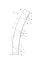
図1〜2は、請求項1に対応する、本発明の実施例1を示している。本発明の合成樹脂製保持器1aは、ポリアミド66、ポリアミド46、ポリフェニレンサルファイド、ポリアセタール等の熱可塑性合成樹脂を母材とし、強度向上の為にガラス繊維を10〜30重量%程度添加したものを、射出成形する事により造る。但し、用途により、合成樹脂製保持器1aに特に十分な弾性を要求する場合には、ガラス繊維等の添加材を添加しない場合も考えられる。又、上記母材となる熱可塑性合成樹脂としては、一般的な工作機械用の主軸を支持する為の円筒ころ軸受用の合成樹脂製保持器の場合には、価格面、或は強度、化学的安定性等の機能面から考えて、ポリアミド66が好適である。これに対して、通常運転時や慣らし運転時の温度条件が著しく厳しく(高温に)なる場合や、より優れた疲労強度、剛性が必要な場合にはポリアミド46が、高温、耐薬品、湿度(吸湿)に対する寸法安定性を特に要求する場合にはポリフェニレンサルファイドが、耐摩耗性を特に要求する場合にはポリアセタールが、それぞれ好適である。   1 and 2 show a first embodiment of the present invention corresponding to claim 1. The synthetic resin cage 1a of the present invention is made of a thermoplastic synthetic resin such as polyamide 66, polyamide 46, polyphenylene sulfide, polyacetal or the like as a base material, and about 10 to 30% by weight of glass fiber added for strength improvement. It is made by injection molding. However, depending on the use, when particularly sufficient elasticity is required for the synthetic resin cage 1a, it may be considered that an additive such as glass fiber is not added. The thermoplastic synthetic resin used as the base material is, in the case of a synthetic resin cage for a cylindrical roller bearing for supporting a main spindle for a general machine tool, in terms of cost, strength, chemical From the viewpoint of functional aspects such as mechanical stability, polyamide 66 is preferred. On the other hand, when the temperature conditions during normal operation or running-in operation become extremely severe (high temperature), or when better fatigue strength and rigidity are required, polyamide 46 has a high temperature, chemical resistance, humidity ( Polyphenylene sulfide is preferable when dimensional stability against moisture absorption is particularly required, and polyacetal is particularly preferable when abrasion resistance is particularly required.

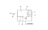
本実施例の合成樹脂製保持器1aの場合には、円周方向等間隔に配置した27本の柱部4、4を、軸方向一端部(図2の左端部)に配置した1個の円環部5に、片持ち式に支持している。そして、これら各柱部4、4の円周方向両側面と上記円環部5の内側面とにより三方を囲まれた部分を、それぞれの内側にころ6、6を転動自在に保持する為の複数のポケット7、7としている。そして、円周方向等間隔位置に存在する3組6本の柱部4、4の他端部(図2の右端部)同士を、抜け止め片に相当する連結枠部8により連結している。この連結枠部8は、上記円環部5に比べ断面積を小さくすると共に円周方向に亙る形状を屈曲させて、円周方向に亙る剛性を低くしている。又、図示の例では、上記連結枠部8の内周縁を上記円環部5の外周縁よりも直径方向外方に位置させて、上記合成樹脂製保持器1aをアキシャルドロー型により造れる様にしている。尚、上記連結枠部8の円周方向に亙る剛性を低くする事は、上記円周方向に亙る形状を屈曲させるのに代えて、或はこの形状を屈曲させると共に、上記合成樹脂製保持器1aを構成するポリアミド樹脂等の合成樹脂中に含有させる、ガラス繊維等の補強材の含有率を、上記連結枠部8部分で少なくする事でも対応できる。   In the case of the synthetic resin cage 1a of the present embodiment, 27 column parts 4, 4 arranged at equal intervals in the circumferential direction are provided as one piece arranged at one end part in the axial direction (left end part in FIG. 2). The annular portion 5 is supported in a cantilever manner. And in order to hold | maintain the roller 6 and 6 so that rolling is possible inside each part enclosed by three sides by the circumferential direction both sides | surfaces of each pillar part 4 and 4 and the inner surface of the said annular part 5 A plurality of pockets 7 and 7. And the other end parts (right end part of FIG. 2) of 3 sets 6 column parts 4 and 4 which exist in the circumferential direction equal intervals position are connected by the connection frame part 8 equivalent to a retaining piece. . The connecting frame portion 8 has a smaller cross-sectional area than the annular portion 5 and a bent shape in the circumferential direction to reduce rigidity in the circumferential direction. Further, in the illustrated example, the inner peripheral edge of the connecting frame portion 8 is positioned diametrically outward from the outer peripheral edge of the annular portion 5 so that the synthetic resin cage 1a can be made by an axial draw type. ing. Note that reducing the rigidity of the connecting frame portion 8 in the circumferential direction can be achieved by bending the shape instead of bending the shape extending in the circumferential direction or by bending the shape. It can also be dealt with by reducing the content of the reinforcing material such as glass fiber contained in the synthetic resin such as polyamide resin constituting 1a in the connecting frame portion 8 portion.

上述の様に構成する本実施例のころ軸受用合成樹脂製保持器1aは、例えば図3〜5に示す様な単列円筒ころ軸受9、9a、9b又は図6に示す様な複列円筒ころ軸受10に組み込む。本実施例の合成樹脂製保持器1aを組み込んだ上記単列円筒ころ軸受9、9a、9b又は複列円筒ころ軸受10を装着した工作機械等を運転する事に伴い、ころ6、6が柱部4、4を強く押圧しても、上記各柱部4、4と円環部5との連結部等、合成樹脂製保持器1aの内部に発生する応力が過大になる事はない。   The synthetic resin cage 1a for roller bearings of the present embodiment configured as described above is, for example, a single row cylindrical roller bearing 9, 9a, 9b as shown in FIGS. 3 to 5 or a double row cylinder as shown in FIG. It is incorporated in the roller bearing 10. As the machine tool or the like equipped with the single-row cylindrical roller bearing 9, 9a, 9b or the double-row cylindrical roller bearing 10 incorporating the synthetic resin cage 1a of this embodiment is operated, the rollers 6, 6 become columns. Even if the portions 4 and 4 are strongly pressed, the stress generated in the synthetic resin cage 1a such as the connecting portion between the column portions 4 and 4 and the annular portion 5 does not become excessive.

即ち、前述の様な原因で、複数のころ6、6のうちの何れかのころ6の公転速度が他のころ6、6の公転速度と異なる結果、この何れかのころ6から当該ころ6が対向する柱部4に、円周方向に亙る大きな力が作用しても、上記円環部5にそれぞれの一端部を片持ち式に支持された柱部4が円周方向に変位する。この変位に基づき、合成樹脂製保持器1aの内部で応力が増大する事を抑制し、この応力が上記合成樹脂製保持器1aを損傷する程大きくなる事を防止できる。この結果、単列円筒ころ軸受9、9a、9b、或は複列円筒ころ軸受10の使用条件がばらつき、組み付け状態が多少不正規であった場合でも、当該単列円筒ころ軸受9、9a、9b或は複列円筒ころ軸受10を組み込んだ、工作機械の主軸等の回転支持部を有する機械装置の高速運転を、長時間に亙り安定して行なえる。又、前記連結枠部8により隣り合う柱部4に対して他端を連結された柱部4に、上記円周方向に亙る大きな力が作用しても、上記連結枠部8が円周方向に伸縮する状態で弾性変形する事により、上記力を吸収して、上記応力が大きくなる事を防止する。   That is, as a result of the reason described above, the revolution speed of any one of the plurality of rollers 6 and 6 is different from the revolution speed of the other rollers 6 and 6. Even when a large force acting in the circumferential direction acts on the column 4 facing each other, the column 4 with one end supported in a cantilever manner on the annular portion 5 is displaced in the circumferential direction. Based on this displacement, it is possible to suppress an increase in stress inside the synthetic resin cage 1a, and to prevent the stress from becoming so large as to damage the synthetic resin cage 1a. As a result, even when the use conditions of the single row cylindrical roller bearings 9, 9a, 9b or the double row cylindrical roller bearing 10 vary and the assembled state is somewhat irregular, the single row cylindrical roller bearings 9, 9a, High-speed operation of a mechanical device having a rotation support portion such as a spindle of a machine tool incorporating the 9b or double row cylindrical roller bearing 10 can be stably performed for a long time. Further, even if a large force acting in the circumferential direction acts on the column part 4 whose other end is connected to the column part 4 adjacent by the connection frame part 8, the connection frame part 8 remains in the circumferential direction. By elastically deforming in a state of expanding and contracting, the force is absorbed and the stress is prevented from increasing.

又、円周方向3個所位置に設けた連結枠部8は、ころ6の端面との係合に基づき、上記合成樹脂製保持器1aがころ6に対して軸方向に変位する事を防止する。従って、本実施例の合成樹脂製保持器1aを図5に示す様な、この合成樹脂製保持器1aの円環部5に対して軸方向に対向する部材を持たない単列円筒ころ軸受9bに組み込んだ場合でも、この合成樹脂製保持器1aが内輪11aの外周面と外輪12の内周面との間から軸方向に抜け落ちる事を防止できる。尚、本実施例の合成樹脂製保持器1aを、図3〜4に示す様な、この合成樹脂製保持器1aの円環部5に対して軸方向に対向する鍔部13或は間座14を有する単列円筒ころ軸受9、9aに組み込む場合には、各部の寸法を次の様に規制する。   Further, the connecting frame portions 8 provided at three positions in the circumferential direction prevent the synthetic resin cage 1a from being displaced in the axial direction with respect to the roller 6 based on the engagement with the end face of the roller 6. . Accordingly, as shown in FIG. 5, the synthetic resin cage 1a of the present embodiment has a single-row cylindrical roller bearing 9b that does not have a member that faces the annular portion 5 of the synthetic resin cage 1a in the axial direction. Even when incorporated into the inner ring 11, the synthetic resin cage 1 a can be prevented from coming off in the axial direction from between the outer peripheral surface of the inner ring 11 a and the inner peripheral surface of the outer ring 12. Incidentally, the synthetic resin cage 1a of the present embodiment is shown in FIGS. 3 to 4 with a flange 13 or a spacer facing the annular portion 5 of the synthetic resin cage 1a in the axial direction. In the case of incorporation in the single-row cylindrical roller bearings 9 and 9 having 14, the dimensions of each part are regulated as follows.

即ち、ころ6の一端面(図3〜4の左端面)と円環部5の片側面(図3〜4の右側面)とを当接させた状態で、上記連結枠部8と上記ころ6の他端面との間に存在する隙間の幅△1 (円環部5と連結枠部8の突部との間隔である、ポケット7の長さをL7 とし、ころ6の長さをL6 とした場合に、△1 =L7 −L6 )を、上記円環部5の他側面(図3〜4の左側面)と上記鍔部13(図3の場合)又は間座14(図4の場合)との間の隙間の幅△2 よりも大きく(△1 >△2 )する。これら各隙間の幅△1 、△2 をこの様に規制する事により、強度の低い上記連結枠部8ところ6の他端面とが擦れ合う事を防止して、この連結枠部8の耐久性確保を図る。 That is, in a state where one end surface of the roller 6 (left end surface in FIGS. 3 to 4) and one side surface of the annular portion 5 (right side surface in FIGS. The width of the gap Δ 1 between the other end face of 6 (the interval between the annular portion 5 and the projection of the connecting frame portion 8 is L 7, and the length of the roller 6 is L 7. In the case of L 6 , Δ 1 = L 7 −L 6 ) is changed to the other side surface (the left side surface in FIGS. 3 to 4) of the annular portion 5 and the flange portion 13 (in the case of FIG. 3) or the spacer 14. greater than the gap width △ 2 between the (case of FIG. 4) (△ 1> △ 2 ) to. By regulating the widths Δ 1 and Δ 2 of these gaps in this way, the low-strength connecting frame portion 8 and the other end surface of the connecting portion 6 are prevented from rubbing, and the durability of the connecting frame portion 8 is ensured. Plan.

尚、合成樹脂製保持器1a全体としての強度は、円環部5により確保できる。従って、上記柱部4を円周方向に弾性変形し易くする事に伴い、合成樹脂製保持器1a全体としての強度が不足する事はない。これに対して、例えば、上記円周方向に亙る力を吸収する事だけを考えれば、円周方向に間隔をあけて配置した複数本の柱部4、4の一端部と他端部とを、円周方向に亙って交互に連続させても、上記円周方向に亙る力を吸収できる。但し、この様な構造を採用した場合には、上記合成樹脂製保持器1aの直径方向に関する上記各柱部4、4の支持剛性が低くなって、上記合成樹脂製保持器1aが高速回転した場合に、上記各柱部4、4が上記合成樹脂製保持器1aの直径方向外方に向け比較的容易に変位し、上記単列円筒ころ軸受9、9a、9b或は複列円筒ころ軸受10を装着した回転機械の運転状態が不安定になる。本実施例の構造の場合は、上記各柱部4、4の一端部を、円周方向に連続した上記円環部5に連続させているので、この様な不都合を生じる事はない。   The strength of the entire synthetic resin cage 1a can be secured by the annular portion 5. Therefore, the strength of the synthetic resin cage 1a as a whole does not become insufficient as the column portion 4 is easily elastically deformed in the circumferential direction. On the other hand, for example, considering only the absorption of the force in the circumferential direction, one end portion and the other end portion of the plurality of column portions 4, 4 arranged at intervals in the circumferential direction. Even when alternately arranged in the circumferential direction, the force in the circumferential direction can be absorbed. However, when such a structure is adopted, the support rigidity of the pillars 4 and 4 in the diameter direction of the synthetic resin cage 1a is reduced, and the synthetic resin cage 1a rotates at high speed. In this case, each of the column parts 4 and 4 is relatively easily displaced outward in the diameter direction of the synthetic resin cage 1a, and the single-row cylindrical roller bearing 9, 9a, 9b or the double-row cylindrical roller bearing. The operating state of the rotating machine equipped with 10 becomes unstable. In the case of the structure of the present embodiment, since one end of each of the pillars 4 and 4 is connected to the annular part 5 that is continuous in the circumferential direction, such a problem does not occur.

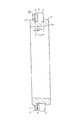
次に、図7は、やはり請求項1に対応する、本発明の実施例2を示している。本実施例の合成樹脂製保持器1bの場合には、円周方向等間隔に配置した28本の柱部4、4を、軸方向一端部(図7の奥側端部)に配置した1個の円環部5に、片持ち式に支持している。そして、円周方向等間隔位置に存在する4組8本の柱部4、4の他端部(図7の手前側端部)同士を、抜け止め片に相当する連結枠部8、8により連結している。柱部の数が4の倍数である28本になった事に伴い、上記連結枠部8、8を円周方向4個所位置に設けた点以外は、上述した実施例1の場合と同様である。尚、上記連結枠部8、8は、合成樹脂製保持器の回転バランスを確保する面から、円周方向に関して等間隔に配置する事が好ましい。但し、使用時の回転速度が遅くてそれ程高度の回転バランスを確保する必要がない場合、或は、各連結枠部8、8の重量を微妙に異ならせて回転バランスを確保できる場合には、必ずしも上記各連結枠部8、8を円周方向に関して等間隔に配置する必要はない。   Next, FIG. 7 shows Embodiment 2 of the present invention, which also corresponds to claim 1. In the case of the synthetic resin cage 1b of the present embodiment, 28 column parts 4 and 4 arranged at equal intervals in the circumferential direction are arranged at one end part in the axial direction (the back end part in FIG. 7). The individual annular portions 5 are supported in a cantilever manner. And the other end portions (front side end portions in FIG. 7) of the four sets of eight column portions 4 and 4 existing at equal circumferential positions are connected to each other by connecting frame portions 8 and 8 corresponding to retaining pieces. It is connected. With the fact that the number of column parts is 28 which is a multiple of 4, the connection frame parts 8 and 8 are the same as in the case of Example 1 described above except that they are provided at four positions in the circumferential direction. is there. In addition, it is preferable to arrange | position the said connection frame parts 8 and 8 at equal intervals regarding the circumferential direction from the surface which ensures the rotational balance of a synthetic resin holder. However, when the rotational speed at the time of use is slow and it is not necessary to secure a high degree of rotational balance, or when the rotational balance can be ensured by slightly varying the weights of the connecting frame portions 8 and 8, It is not always necessary to arrange the connecting frame portions 8 and 8 at equal intervals in the circumferential direction.

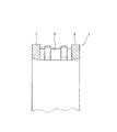
次に、図8は、やはり請求項1に対応する、本発明の実施例3を示している。本実施例の合成樹脂製保持器1cの場合には、円環部5の軸方向片面にそれぞれの一端部を連続させて、この円環部5に片持ち式に支持した複数の柱部4のうち、少なくとも一部の柱部4の他端面に、抜け止め片である突片15を形成している。この突片15は、ポケット7内に保持されたころの端面と係合して上記合成樹脂製保持器1cがころに対して軸方向に変位する事を防止する。そして、本実施例の合成樹脂製保持器1cを図5に示す様な単列円筒ころ軸受9bに組み込んだ場合でも、この合成樹脂製保持器1cが内輪11aの外周面と外輪12の内周面との間から軸方向に抜け落ちる事を防止する。その他の構成及び作用は、前述した実施例1の場合と同様である。   Next, FIG. 8 shows Embodiment 3 of the present invention, which also corresponds to claim 1. In the case of the synthetic resin cage 1c according to the present embodiment, a plurality of column portions 4 supported in a cantilever manner on the annular portion 5 with one end portion being continuous with one axial surface of the annular portion 5. Among them, a protruding piece 15 as a retaining piece is formed on the other end face of at least a part of the column part 4. The protruding piece 15 engages with the end face of the roller held in the pocket 7 to prevent the synthetic resin cage 1c from being displaced in the axial direction with respect to the roller. Even when the synthetic resin cage 1c of the present embodiment is incorporated in a single row cylindrical roller bearing 9b as shown in FIG. 5, the synthetic resin cage 1c is provided with the outer circumferential surface of the inner ring 11a and the inner circumference of the outer ring 12. Prevents falling off from the surface in the axial direction. Other configurations and operations are the same as those of the first embodiment.

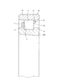
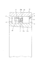
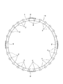
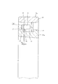
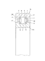
次に、図9〜10は、請求項2に対応する、本発明の実施例4を示している。本実施例の合成樹脂製保持器1dも、軸方向一端部に配置された円環部5の片側面に、円周方向に亙って互いに等間隔に配置された複数本の柱部4、4の一端部を連続させて、これら複数本の柱部4、4を上記円環部5に、片持ち式に支持している。そして、これら各柱部4、4の円周方向両側面と上記円環部5の片側面とにより三方を囲まれた部分を、それぞれの内側にころ6(図11)を転動自在に保持する複数のポケット7、7としている。   Next, FIGS. 9 to 10 show a fourth embodiment of the present invention corresponding to claim 2. The synthetic resin cage 1d of the present embodiment also has a plurality of column portions 4 arranged at equal intervals along the circumferential direction on one side surface of the annular portion 5 arranged at one end portion in the axial direction. The plurality of column portions 4 and 4 are supported by the annular portion 5 in a cantilever manner with one end portion of the four being continuous. And the roller 6 (FIG. 11) is hold | maintained so that the part enclosed by three sides by the circumferential direction both sides | surfaces of each pillar part 4 and 4 and the one side surface of the said ring part 5 can be rolled inside each. A plurality of pockets 7 and 7 are provided.

特に、本実施例のころ軸受用合成樹脂製保持器1dの場合には、上記複数本の柱部4、4のうち、少なくとも一部の柱部4、4の内周面部に、三角形状の係合突起16、16を突設している。これら各係合突起16、16は、上記合成樹脂製保持器1dを、図11に示す様な単列円筒ころ軸受9b、或は図12に示す様な複列円筒ころ軸受10に組み込んだ場合に、内輪11a、11bの外周面に形成した鍔部17、17aの内側面と係合して、上記合成樹脂製保持器1dが、内輪11a、11bの外周面と外輪12、12aの内周面との間から軸方向に抜け落ちる事を防止する。この為に、上記合成樹脂製保持器1dの自由状態での、上記複数の係合突起16、16の内接円の直径は、上記鍔部17、17aの外径よりも少しだけ小さくしている。   In particular, in the case of the synthetic resin cage 1d for roller bearings of the present embodiment, a triangular shape is formed on the inner peripheral surface portion of at least some of the column portions 4, 4 among the plurality of column portions 4, 4. Engaging protrusions 16 and 16 are provided. These engaging protrusions 16 and 16 are formed when the above-mentioned synthetic resin cage 1d is incorporated in a single row cylindrical roller bearing 9b as shown in FIG. 11 or a double row cylindrical roller bearing 10 as shown in FIG. The synthetic resin retainer 1d is engaged with the inner surface of the flanges 17 and 17a formed on the outer peripheral surface of the inner rings 11a and 11b, and the outer peripheral surface of the inner rings 11a and 11b and the inner periphery of the outer rings 12 and 12a. Prevents falling off from the surface in the axial direction. Therefore, the diameter of the inscribed circle of the plurality of engaging protrusions 16 and 16 in the free state of the synthetic resin cage 1d is slightly smaller than the outer diameter of the flange portions 17 and 17a. Yes.

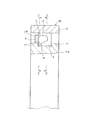
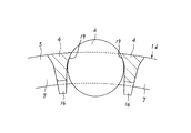
尚、本実施例を実施する場合に、上記各係合突起16、16のうち、内輪11a、11bの外周面に形成した鍔部17、17aと対向する面は、これら各鍔部17、17aの側面に付着しているグリースを過度に掻き取らない様な形状にする事が好ましい。図13〜18に、この様なグリースの過度の掻き取りを防止する為の形状の3例を示している。先ず、図13〜14に示した第1例は、上記係合突起16の一部で上記各鍔部17、17aに対向する面の円周方向両端部に面取り18、18を形成したもの、図15〜16に示した第2例は、上記係合突起16の一部で上記各鍔部17、17aに対向する面全体を部分円筒面状の凸面としたもの、図17〜18に示した第3例は、上記係合突起16の一部で上記各鍔部17、17aに対向する面全体を、中央部が尖った山形の凸面としたものである。   When the present embodiment is carried out, the surface of the engagement protrusions 16 and 16 that faces the flanges 17 and 17a formed on the outer peripheral surfaces of the inner rings 11a and 11b is the flanges 17 and 17a. It is preferable to make the shape so as not to scrape off excessively the grease adhering to the side surface. FIGS. 13 to 18 show three examples of shapes for preventing excessive scraping of such grease. First, in the first example shown in FIGS. 13 to 14, chamfers 18 and 18 are formed at both ends in the circumferential direction of the surface of the engagement protrusion 16 that faces the flanges 17 and 17 a. The second example shown in FIGS. 15 to 16 shows a part of the engaging projection 16 that has a part of the entire surface facing the flanges 17 and 17a as a partially cylindrical convex surface, as shown in FIGS. In the third example, the entire surface of the engaging protrusion 16 that faces the flanges 17 and 17a is an angled convex surface with a sharp central portion.

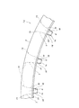
尚、図9〜10に示した、本発明の実施例4の場合には、前記各柱部4、4の円周方向両側面を、上記合成樹脂製保持器1dの直径方向外側部分の曲面部19と直径方向内側の平坦部20とを滑らかに連続させた形状としている。このうちの曲面部19の曲率半径は、ポケット7内に保持すべくころ6の転動面の曲率半径よりも僅かに(0.5〜10%程度)大きくしている。又、同一のポケット7の円周方向両内側面の直径方向中間部から内径側部分を構成する1対の平坦部20、20同士は互いに平行にしている。又、上記同一のポケット7の円周方向両内側面の外径側部分を構成する1対の曲面部19、19同士の間隔は、上記ポケット7の外径側開口に向かう程狭くなる様にしている。   In addition, in the case of Example 4 of the present invention shown in FIGS. 9 to 10, both the circumferential side surfaces of the pillars 4 and 4 are curved surfaces of the outer portions in the diameter direction of the synthetic resin cage 1d. The portion 19 and the flat portion 20 on the inner side in the diameter direction are smoothly continuous. Of these, the radius of curvature of the curved surface portion 19 is slightly larger (about 0.5 to 10%) than the radius of curvature of the rolling surface of the roller 6 to be held in the pocket 7. Further, a pair of flat portions 20, 20 constituting the inner diameter side portion from the diametrically intermediate portion of both inner circumferential surfaces of the same pocket 7 are parallel to each other. Further, the distance between the pair of curved surface portions 19, 19 constituting the outer diameter side portions of both inner surfaces in the circumferential direction of the same pocket 7 is made narrower toward the outer diameter side opening of the pocket 7. ing.

上記各柱部4、4の円周方向両側面の形状を上述の様にする事により、それぞれが前記円環部5の片側面に片持ち支持された上記各柱部4、4が、運転時に作用する遠心力に基づいて、上記合成樹脂製保持器1dの直径方向外方に変位した場合でも、上記各柱部4、4の円周方向両側面と上記ころ6の転動面とが強く摩擦し合う事がない。即ち、上記各柱部4、4の円周方向両内側面の内径側部分を構成する上記1対の平坦部20、20同士の間隔は、上記各柱部4、4が直径方向外方に変位しても狭まる事はなく、上記各柱部4、4の円周方向両側面と上記ころ6の転動面とが強く摩擦し合わない。これに対して、上記各柱部4、4の円周方向両側面を内径側まで湾曲した円筒面とし、円周方向に亙るポケットの幅寸法が、直径方向中間部よりも内径側開口で狭くなる様にすると、運転時に作用する遠心力に基づいて上記各柱部4、4が、上記合成樹脂製保持器1dの直径方向外方に変位した場合に、上記各柱部4、4の円周方向両側面と上記ころ6の転動面とが強く摩擦し合う可能性がある為、好ましくない。   By making the shape of both side surfaces in the circumferential direction of the pillars 4 and 4 as described above, the pillars 4 and 4 that are cantilevered on one side of the annular part 5 are operated. Even if the synthetic resin cage 1d is displaced outward in the diameter direction based on the centrifugal force acting at times, the circumferential side surfaces of the pillars 4 and 4 and the rolling surfaces of the rollers 6 are not affected. There is no strong friction. That is, the interval between the pair of flat portions 20 and 20 constituting the inner diameter side portions of both inner circumferential surfaces of the column portions 4 and 4 is such that the column portions 4 and 4 are diametrically outward. Even if it displaces, it does not narrow, and both side surfaces in the circumferential direction of the pillars 4 and 4 and the rolling surfaces of the rollers 6 do not rub strongly. On the other hand, both the circumferential side surfaces of the pillars 4 and 4 are cylindrical surfaces curved to the inner diameter side, and the width dimension of the pocket extending in the circumferential direction is narrower at the inner diameter side opening than the diametrically intermediate portion. Then, when each said pillar part 4 and 4 is displaced to the diameter direction outer side of the said synthetic resin holder 1d based on the centrifugal force which acts at the time of a driving | operation, the circle | round | yen of each said pillar part 4 and 4 is carried out. Since both sides of the circumferential direction and the rolling surface of the roller 6 may rub against each other, it is not preferable.

又、上記各ポケット7の外径側口部の円周方向に亙る幅W7 は、このポケット7に保持するころ6の直径D6 (図11)の0.7〜0.9倍{W7 =(0.7〜0.9)D6 }の範囲に規制する事が好ましい。上記幅W7 がこれよりも広い(W7 >0.9D6 )と、遠心力に基づいて隣り合う柱部4、4同士の間隔が開いた場合に、上記ころ6が上記ポケット7の外径側開口部に噛み込まれ、ころ6の転動が阻害される可能性がある。反対に、上記幅W7 をこれよりも狭くする(W7 <0.7D6 )為には、上記合成樹脂製保持器1dの直径方向に亙る上記各柱部4、4の厚さT4 を大きくする必要が生じる。この結果、ころ軸受を構成する外輪12、12aの内周面と上記合成樹脂製保持器1dとが干渉し易くなったり、或は上記外輪12、12aの内周面に存在するグリースを上記各柱部4、4の外周縁が掻き取り、外輪軌道ところ6の転動面との間の潤滑不良を生じ易くなる等の問題を生じる。 Further, the circumferential width W 7 of the outer diameter side opening of each pocket 7 is 0.7 to 0.9 times the diameter D 6 (FIG. 11) of the roller 6 held in this pocket 7 {W It is preferable to regulate in the range of 7 = (0.7 to 0.9) D 6 }. When the width W 7 is wider than this (W 7 > 0.9D 6 ), the rollers 6 are located outside the pocket 7 when the interval between the adjacent column parts 4 and 4 is opened based on centrifugal force. There is a possibility that rolling of the roller 6 is inhibited by being caught in the opening on the radial side. Conversely, the width W 7 narrower than this (W 7 <0.7D 6) The order, the thickness T 4 of the synthetic resin cage 1d of over the diametrical direction the column sections 4, 4 Need to be increased. As a result, the inner peripheral surface of the outer ring 12, 12a constituting the roller bearing and the synthetic resin cage 1d are likely to interfere with each other, or the grease existing on the inner peripheral surface of the outer ring 12, 12a The outer peripheral edges of the column portions 4 and 4 are scraped off, causing problems such as poor lubrication between the outer ring raceway 6 and the rolling surface.

更に、上記各ポケット7の外径側開口部には、図19に示す様な面取り21、21を施す事により、この外径側開口部で上記ころ6の転動面に付着したグリースを過度に掻き取らない様にする事が好ましい。この目的を達成する為に、合成樹脂製保持器1dの直径方向に対する上記各面取り21、21の面取り角度αは、0度よりも大きく、上記外径側開口部の開口角度βよりも小さくする。更に好ましくは、上記面取り角度αを、上記開口角度βよりも10度以上小さくする(α≦β−10度)。尚、この開口角度βとは、曲面部19、19を曲率半径を変えずにそのまま延長したと仮定した場合に、上記各ポケット7の外径側開口部に於けるこれら各曲面部19、19に対する接線とこれら各ポケット7の中心と上記合成樹脂製保持器1dの中心とを通過する直線との交差角度を言う。又、上述の様な各条件を満たす合成樹脂製保持器1dを、前記図11に示す様な単列円筒ころ軸受9b、或は図12に示す様な複列円筒ころ軸受10に組み込んだ場合、前記各係合突起16と鍔部17、17aとの間には、適度な隙間△3 (図11参照。例えば△3 ≒0.1〜2mm)を持たせる。この様な適度な隙間△3 を持たせる事により、運転時に円筒ころ軸受が振動を受けたり、或は上記合成樹脂製保持器1dが振動した場合でも、円滑な運転状態を維持できる。 Furthermore, the chamfers 21 and 21 as shown in FIG. 19 are applied to the outer diameter side openings of the pockets 7 so that the grease adhering to the rolling surfaces of the rollers 6 at the outer diameter side openings is excessive. It is preferable not to scrape off. In order to achieve this object, the chamfering angle α of each of the chamfers 21 and 21 with respect to the diameter direction of the synthetic resin cage 1d is larger than 0 degree and smaller than the opening angle β of the outer diameter side opening. . More preferably, the chamfer angle α is set to be smaller than the opening angle β by 10 degrees or more (α ≦ β−10 degrees). Note that the opening angle β means that the curved surface portions 19 and 19 at the outer diameter side opening portions of the pockets 7 are assumed when the curved surface portions 19 and 19 are extended without changing the radius of curvature. And the angle of intersection between the center of each pocket 7 and the straight line passing through the center of the synthetic resin cage 1d. When the synthetic resin cage 1d satisfying the above conditions is incorporated in the single row cylindrical roller bearing 9b as shown in FIG. 11 or the double row cylindrical roller bearing 10 as shown in FIG. An appropriate gap Δ 3 (see FIG. 11, for example, Δ 3 ≈0.1 to 2 mm) is provided between each engaging protrusion 16 and the flange portions 17 and 17a. By giving such a modest gap △ 3, cylindrical roller bearing or subjected to vibration during operation, or even when the synthetic resin cage 1d is vibrated, can be maintained smooth operating condition.

次に、本発明を実施する場合に好ましい形状、寸法等に就いて説明する。先ず、柱部4の長さに就いて説明する。
弾性変形し易い合成樹脂製保持器1dに片持ち式に設ける柱部4の長さに就いて、本発明者が実験・解析を行なったところ、この長さに関する最適な範囲がある事が分った。
先ず、図20は、上記柱部4の長さが短い場合を示している。又、この図20は、前述の図11に示した単列円筒ころ軸受9b、或は図12に示した複列円筒ころ軸受10の様な、外輪12、12aに鍔部を持たず、内輪11a、11bの外周面にのみ鍔部17、17aを持った構造を組み立てる途中の段階を示している。この段階で複数のころ6、6は、内輪11aの外周面上に合成樹脂製保持器1dを構成する柱部4、4の先端部に、引っ掛る様に保持されている。この為、これら各柱部4、4の長さが短いと、円周方向に隣り合う柱部4、4同士の間に存在するポケット7、7内からころ6、6が脱落し易い。
Next, preferred shapes, dimensions, etc. when implementing the present invention will be described. First, the length of the column part 4 will be described.
As a result of experiments and analysis by the present inventor on the length of the column 4 provided in a cantilever manner on the synthetic resin cage 1d that is easily elastically deformed, it is found that there is an optimum range regarding this length. It was.
First, FIG. 20 shows a case where the length of the column part 4 is short. Further, FIG. 20 shows that the outer ring 12 and 12a, such as the single-row cylindrical roller bearing 9b shown in FIG. 11 or the double-row cylindrical roller bearing 10 shown in FIG. The stage in the middle of assembling the structure which has the flange parts 17 and 17a only on the outer peripheral surface of 11a and 11b is shown. At this stage, the plurality of rollers 6 and 6 are held on the outer peripheral surface of the inner ring 11a so as to be caught by the tip portions of the column parts 4 and 4 constituting the synthetic resin cage 1d. For this reason, when the length of each of the column portions 4 and 4 is short, the rollers 6 and 6 are easily dropped from the pockets 7 and 7 existing between the column portions 4 and 4 adjacent to each other in the circumferential direction.

特に、上記合成樹脂製保持器1dは、銅合金等により造られる金属製の保持器に比べて剛性が低い、この為、図20〜21に示す様に、この合成樹脂製保持器1dの中心軸を水平方向に配置した横軸状態では、上記各柱部4、4が、上記各ポケット7、7内に保持されたころ6、6の重量により撓み易く、撓んだ場合には更にこれら各ポケット7、7からころ6、6が外れ易くなる。本発明者が行なった実験・解析によれば、上記合成樹脂製保持器1dを、工作機械の主軸の回転支持部に組み込む程度の大きさを有する円筒ころ軸受用として実施する場合には、上記各柱部4、4の長さL4 が上記各ころ6、6の軸方向長さL6 の50%以下の場合(L4 ≦0.5L6 )に、円筒ころ軸受の組み付け途中でころ6、6が上記合成樹脂製保持器1dから外れ易くなる事が分った。 In particular, the synthetic resin cage 1d is less rigid than a metal cage made of a copper alloy or the like. Therefore, as shown in FIGS. In the horizontal axis state in which the shafts are arranged in the horizontal direction, the column parts 4, 4 are easily bent due to the weight of the rollers 6, 6 held in the pockets 7, 7. The rollers 6 and 6 are easily detached from the pockets 7 and 7. According to the experiments and analysis conducted by the present inventors, when the synthetic resin cage 1d is used for a cylindrical roller bearing having a size of being incorporated into the rotation support portion of the spindle of the machine tool, When the length L 4 of each column part 4, 4 is 50% or less of the axial length L 6 of each roller 6, 6 (L 4 ≦ 0.5 L 6 ), the roller is in the middle of assembling the cylindrical roller bearing. 6 and 6 were found to be easily detached from the synthetic resin cage 1d.

一方、上記各柱部4、4の長さL4 の上限値は、上述の様なころ6、6の外れ防止の面からではなく、円筒ころ軸受の安定した運転の確保の面から規制する必要がある。図22に、上記各柱部4、4の長さL4 が長い場合を示している。この図22に示した様に柱部4が長くなると、柱部4自体の重量が増えるだけでなく、この柱部4の重心が、この柱部4の支持部である円環部5から離れる。この為、合成樹脂製保持器1dの公転運動に伴って各柱部4に加わる遠心力が大きくなり、高速運転時の遠心力に基づく上記柱部4の変形量が、上記長さL4 の増大に伴って2次曲線的に大きくなる。この結果、この柱部4の長さL4 が大きく、合成樹脂製保持器1dを組み込んだ円筒ころ軸受が高速運転された場合には、上記柱部4がこの合成樹脂製保持器1dの直径方向外方に変位し、この柱部4の先端部外周縁が外輪12の内周面と干渉してしまう。この様な干渉が発生すると、円筒ころ軸受の回転抵抗が大きくしかも不安定になるだけでなく、運転時に於ける発熱量が多くなる為、好ましくない。従って、上記各柱部4、4の長さL4 は、円筒ころ軸受の安定した運転の確保の面からは、できるだけ短い方が有利である。 On the other hand, the upper limit of the length L 4 of the column sections 4, 4, rather than in terms of preventing the edge of such rollers 6,6 described above and restriction in terms of ensuring the stable operation of the cylindrical roller bearing There is a need. FIG. 22 shows a case where the length L 4 of each of the pillars 4 and 4 is long. As shown in FIG. 22, when the column portion 4 becomes long, not only does the weight of the column portion 4 itself increase, but the center of gravity of the column portion 4 moves away from the annular portion 5 that is the support portion of the column portion 4. . For this reason, the centrifugal force applied to each column part 4 increases with the revolution movement of the synthetic resin cage 1d, and the deformation amount of the column part 4 based on the centrifugal force during high-speed operation is the length L 4 . As it increases, it becomes larger in a quadratic curve. As a result, when the length L 4 of the column 4 is large and the cylindrical roller bearing incorporating the synthetic resin cage 1d is operated at high speed, the column 4 has a diameter of the synthetic resin cage 1d. The outer peripheral edge of the columnar portion 4 interferes with the inner peripheral surface of the outer ring 12. Such interference is not preferable because not only the rotational resistance of the cylindrical roller bearing becomes large and unstable, but also the amount of heat generated during operation increases. Accordingly, it is advantageous that the length L 4 of each of the column parts 4 and 4 is as short as possible from the viewpoint of ensuring stable operation of the cylindrical roller bearing.

以上の事を考慮すると、ころ6、6の脱落防止を図ると共に、高速運転時に柱部4、4の先端部外周縁と外輪12の内周面との干渉防止を図る為には、これら各柱部4、4の長さL4 を、ころ6、6の軸方向長さL6 の50%を超え100%以下(0.5L6 <L4 ≦L6 )、更に最適には、図23に示す様に、この軸方向長さL6 の60〜80%{L4 =(0.6〜0.8)L6 )程度とする事が望ましい。 In consideration of the above, in order to prevent the rollers 6 and 6 from falling off, and to prevent interference between the outer peripheral edge of the pillars 4 and 4 and the inner peripheral surface of the outer ring 12 during high speed operation, the length L 4 of the pillar portions 4, 100% or less than 50% of the axial length L 6 of the rollers 6,6 (0.5L 6 <L 4 ≦ L 6), and more optimally, Fig. 23, it is desirable that the axial length L 6 is about 60 to 80% (L 4 = (0.6 to 0.8) L 6 ).

尚、図24に示す様に、ころ6の1列毎に合成樹脂製保持器1d、1dを2個を使用し、これら各合成樹脂製保持器1d、1dの柱部4、4の長さを、これら各合成樹脂製保持器1d、1dの軸方向動き量を考慮した上で、これら各合成樹脂製保持器1d、1dからころ6、6が外れない範囲でできるだけ短くする構造も考えられる。この様な構造を採用する場合に、上記各合成樹脂製保持器1d、1dを構成する柱部4、4の長さは、上記各ころ6、6の軸方向長さの50%未満、更に好ましくは30%以下とする。この様に、合成樹脂製保持器1d、1dを2個使用する事により、これら各合成樹脂製保持器1d、1dからのころ6、6の脱落防止を図りつつ、柱部4、4が直径方向外方に変形する事を僅少に抑えて、より高速での使用を可能にできる。   24, two synthetic resin cages 1d and 1d are used for each row of rollers 6, and the lengths of the column portions 4 and 4 of these synthetic resin cages 1d and 1d are used. Considering the amount of axial movement of each of these synthetic resin cages 1d and 1d, it is possible to consider a structure in which the rollers 6 and 6 are not removed from these synthetic resin cages 1d and 1d as much as possible. . When such a structure is adopted, the lengths of the column parts 4 and 4 constituting the synthetic resin cages 1d and 1d are less than 50% of the axial length of the rollers 6 and 6, respectively. Preferably it is 30% or less. Thus, by using two synthetic resin cages 1d and 1d, the columns 4 and 4 have a diameter while preventing the rollers 6 and 6 from falling off from the respective synthetic resin cages 1d and 1d. It can be used at higher speeds with minimal deformation to the outside of the direction.

又、本発明のころ軸受用合成樹脂製保持器は、各柱部4、4の基端部を円環部5に対して結合すると共に、これら各柱部4、4の先端部同士は離隔させているので、潤滑条件が改善される。そこで、本発明の合成樹脂製保持器1dを組み込んだ円筒ころ軸受と、前述の図31に示した様な従来の合成樹脂製保持器1を組み込んだ円筒ころ軸受とを実際に運転して潤滑性を比較する実験を行なった。この実験の結果、本発明の合成樹脂製保持器1dを組み込んだ円筒ころ軸受は、従来の合成樹脂製保持器1を組み込んだ円筒ころ軸受に比較して、特に微量潤滑で著しい高速化を達成できる事が分った。   In the synthetic resin cage for roller bearings of the present invention, the base end portions of the column portions 4 and 4 are coupled to the annular portion 5, and the tip portions of the column portions 4 and 4 are separated from each other. Therefore, the lubrication conditions are improved. Therefore, the cylindrical roller bearing incorporating the synthetic resin cage 1d of the present invention and the cylindrical roller bearing incorporating the conventional synthetic resin cage 1 as shown in FIG. 31 are actually operated and lubricated. Experiments were conducted to compare sex. As a result of this experiment, the cylindrical roller bearing incorporating the synthetic resin cage 1d of the present invention achieves a significant increase in speed especially with a minute amount of lubrication, compared to the conventional cylindrical roller bearing incorporating the synthetic resin cage 1. I knew what I could do.

実験は以下の条件で行ない、内輪を外嵌固定した回転軸の回転速度を、各回転数で温度的に平衡状態になる事を確認しつつ、段階的に増速した。そして、温度が安定しなくなる回転数を、最高許容回転数とした。
実験条件
使用した円筒ころ軸受 : N1014(内径70mm・1/12テーパ孔、外径110mm、幅20mm、ころサイズ:径9mm×長さ9mm)
保持器寸法 : 外径97mm、内径87mm、円環部の軸方向厚さ2.3mm、柱部の長さ6.3mm(ころの軸方向長さの70%)
保持器の材質 : ガラス繊維を30重量%含有したポリアミド46
The experiment was conducted under the following conditions, and the rotational speed of the rotating shaft with the inner ring fitted and fixed was increased stepwise while confirming that the rotational speed reached an equilibrium state at each rotational speed. The rotation speed at which the temperature becomes unstable is set as the maximum allowable rotation speed.
Experimental conditions Cylindrical roller bearing used: N1014 (inner diameter 70 mm, 1/12 tapered hole, outer diameter 110 mm, width 20 mm, roller size: diameter 9 mm x length 9 mm)
Cage dimensions: 97 mm outer diameter, 87 mm inner diameter, 2.3 mm axial thickness of the annular part, 6.3 mm column length (70% of the axial length of the roller)
Cage Material: Polyamide 46 containing 30% glass fiber

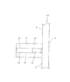
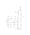
実験に使用した試験装置の構造を図25に示す。ハウジング22内に回転軸23を支持する為の複数個の転がり軸受のうち、最上段の転がり軸受を、試験片である単列円筒ころ軸受9とし、この単列円筒ころ軸受9に微量の潤滑油を供給した。潤滑条件は、ノズル24からオイルエアを噴出するオイルエア潤滑とし、このノズル24から上記単列円筒ころ軸受9に向けて、VG32タービン油を含むオイルエアを、16分毎に、タービン油の容量にして0.01ccずつ供給した。この様な実験を、図23に示した様な本発明の合成樹脂製保持器1dを組み込んだ円筒ころ軸受と、前述の図31に示した様な従来の合成樹脂製保持器1を組み込んだ円筒ころ軸受とに就いて行なった。その結果を図26に示す。この図26中、実線αは本発明の合成樹脂製保持器1dを組み込んだ円筒ころ軸受に就いての実験結果を、破線βは従来の合成樹脂製保持器1を組み込んだ円筒ころ軸受に就いての実験結果を、それぞれ表している。   The structure of the test apparatus used for the experiment is shown in FIG. Of the plurality of rolling bearings for supporting the rotating shaft 23 in the housing 22, the uppermost rolling bearing is a single-row cylindrical roller bearing 9 as a test piece, and a small amount of lubrication is added to the single-row cylindrical roller bearing 9. Oil was supplied. The lubrication condition is oil-air lubrication in which oil air is ejected from the nozzle 24, and oil air containing VG32 turbine oil from the nozzle 24 toward the single-row cylindrical roller bearing 9 is set to a turbine oil capacity of 16 every 16 minutes. .01 cc was supplied. Such an experiment was performed by incorporating the cylindrical roller bearing incorporating the synthetic resin cage 1d of the present invention as shown in FIG. 23 and the conventional synthetic resin cage 1 as shown in FIG. This was done with a cylindrical roller bearing. The result is shown in FIG. In FIG. 26, the solid line α represents the experimental result of the cylindrical roller bearing incorporating the synthetic resin cage 1d of the present invention, and the broken line β represents the cylindrical roller bearing incorporating the conventional synthetic resin cage 1. The experimental results are shown respectively.

図26に示した実験結果から明らかな通り、本発明の合成樹脂製保持器1dを組み込んだ円筒ころ軸受は、従来の合成樹脂製保持器1を組み込んだ円筒ころ軸受に比べて、格段の高速化を達成できる。この点に就いて、以下に考察する。
オイルエア潤滑、オイルミスト潤滑に代表される微量潤滑は、多量の圧縮空気に微量の油を混合した状態で転がり軸受に吹付ける。この為、微量の潤滑油が確実に転がり軸受内部にまで到達し、しかも到達した潤滑油がこの転がり軸受の撹拌抵抗にならない様に、速やかに排出される必要がある。本発明の対象となる合成樹脂製保持器を組み込む円筒ころ軸受は、玉軸受に比べて潤滑油の入排出性に劣るが、本発明の合成樹脂製保持器1dは、各柱部4、4の基端部のみを円環部5に対して、片持ち式に支持している為、ころ6、6を覆う部分が、従来の合成樹脂製保持器1の様に、各柱部4、4の両端部が両持ち式に支持されているものに比べて少なく、油の入排出性が増す。この為、特に微量潤滑での高速運転で優れた温度安定性を示すものと考えられる。
As is apparent from the experimental results shown in FIG. 26, the cylindrical roller bearing incorporating the synthetic resin cage 1d of the present invention is much faster than the conventional cylindrical roller bearing incorporating the synthetic resin cage 1. Can be achieved. This point will be discussed below.
Micro lubrication represented by oil-air lubrication and oil mist lubrication sprays rolling bearings in a state where a small amount of oil is mixed in a large amount of compressed air. For this reason, a small amount of lubricating oil must surely reach the inside of the rolling bearing, and the reached lubricating oil needs to be quickly discharged so as not to become the stirring resistance of the rolling bearing. The cylindrical roller bearing incorporating the synthetic resin cage, which is the subject of the present invention, is inferior in lubricating oil in and out compared to ball bearings. However, the synthetic resin cage 1d of the present invention has the pillars 4, 4. Are supported in a cantilevered manner with respect to the annular portion 5, so that the portions covering the rollers 6, 6 are each pillar portion 4, like the conventional synthetic resin cage 1. The both ends of 4 are less than those supported in a double-supported manner, and the oil entry / exit is increased. For this reason, it is considered that excellent temperature stability is exhibited particularly at high speed operation with a minute amount of lubrication.

尚、上記した実験を通じて、ころ6、6により案内される合成樹脂製保持器(ころ6、6にのみ接触しながら運転される様に、合成樹脂製保持器の内外両周面と内輪外周面及び外輪内周面との間の隙間寸法を十分に設定したもの)であっても、運転中に円環部5が楕円状等に変形し、この円環部5の内外両周面が、内輪外周面や外輪内周面と接触する場合がある事が分った。ころ6、6により案内される合成樹脂製保持器を使用する円筒ころ軸受の場合には、内輪の外周面で内輪軌道から外れた鍔部17、17の外周面部分は、本来ならば他の部品と干渉しないので、通常は仕上状態に特別な配慮をせず、面粗度の大きな旋削面、熱処理面のままとする事がある。但し、今回の実験により、各柱部4、4の基端部のみを円環部5に対して片持ち式に支持する、本発明の合成樹脂製保持器1dの場合は、ころ6、6により案内される合成樹脂製保持器であっても、上記各鍔部17、17のうち、少なくとも上記円環部5の内周面と対向する鍔部17の外周面を例えば研削仕上げとし、面粗度を向上させる事が好ましい。即ち、この部分の面粗度を向上させる事により、上記合成樹脂製保持器1dの円環部5の内周面と鍔部17の外周面とが干渉しても、これら両周面同士の当接部の摩擦抵抗が少なく、摩耗・発熱と言った問題の発生を防止できる。尚、この場合に、上記鍔部17の外周面の面粗度は、1S〜3S程度にすれば、摩耗防止効果とコスト上昇の抑制とを両立させる面からは好ましい。   Through the experiments described above, the synthetic resin cage guided by the rollers 6 and 6 (both the inner and outer peripheral surfaces of the synthetic resin cage and the outer peripheral surface of the inner ring so as to be operated only in contact with the rollers 6 and 6). Even when the gap between the inner ring and the outer ring is sufficiently set), the annular part 5 is deformed into an elliptical shape during operation, and both the inner and outer peripheral surfaces of the annular part 5 are It has been found that there is a case where the inner ring outer peripheral surface or the outer ring inner peripheral surface may come into contact. In the case of a cylindrical roller bearing using a synthetic resin cage guided by the rollers 6 and 6, the outer peripheral surface portions of the flange portions 17 and 17 that are off the inner ring raceway on the outer peripheral surface of the inner ring are originally other Since it does not interfere with the parts, it usually does not give special considerations to the finished state, and may remain a turning surface or heat-treated surface with a large surface roughness. However, in this experiment, in the case of the synthetic resin cage 1d of the present invention in which only the base end portions of the pillar portions 4 and 4 are supported in a cantilever manner with respect to the annular portion 5, the rollers 6 and 6 Even in the case of the synthetic resin cage guided by the above, the outer peripheral surface of at least the flange portion 17 facing the inner peripheral surface of the annular portion 5 is ground, for example, of the flange portions 17, 17. It is preferable to improve the roughness. That is, by improving the surface roughness of this portion, even if the inner peripheral surface of the annular portion 5 and the outer peripheral surface of the flange portion 17 of the synthetic resin cage 1d interfere with each other, The frictional resistance of the abutting portion is small, and problems such as wear and heat generation can be prevented. In this case, if the surface roughness of the outer peripheral surface of the flange portion 17 is about 1S to 3S, it is preferable from the viewpoint of achieving both the wear prevention effect and the suppression of the cost increase.

次に、各柱部4の方向性に就いて、図27〜29を参照しつつ述べる。これら各柱部4を互いに平行にし、円環部5に対して垂直になる様に造ると、前述の図21で述べた様に、円筒ころ軸受の組立途中で上記各柱部4が、ころ6の重量により弾性変形した場合に、これら各ころ6がポケット7から脱落し易くなる。そこで、図27に示す様に、上記各柱部4を、先端部程合成樹脂製保持器1dの直径方向内方に向かう方向に傾斜する様に造っておけば、円筒ころ軸受の組立途中で上記各柱部4が、ころ6の重量により弾性変形しても、これら各ころ6がポケット7から脱落しにくくなる。又、高速回転時に上記各柱部4が、合成樹脂製保持器1dの直径方向外方に弾性変形しても、これら各柱部4の先端部外周縁と外輪12の内周面とが干渉しにくくなる。   Next, the directionality of each column part 4 will be described with reference to FIGS. When these column portions 4 are made parallel to each other and perpendicular to the annular portion 5, as described with reference to FIG. 21, the column portions 4 are in contact with the roller during the assembly of the cylindrical roller bearing. When the roller 6 is elastically deformed by the weight of the roller 6, the rollers 6 are easily dropped from the pocket 7. Therefore, as shown in FIG. 27, if each of the column parts 4 is formed so as to incline in the direction toward the diametrically inward direction of the synthetic resin retainer 1d, the cylindrical roller bearing is being assembled. Even if each of the column portions 4 is elastically deformed due to the weight of the rollers 6, the rollers 6 are less likely to fall out of the pockets 7. Further, even when each of the column parts 4 is elastically deformed outward in the diameter direction of the synthetic resin cage 1d during high-speed rotation, the outer peripheral edge of each of the column parts 4 interferes with the inner peripheral surface of the outer ring 12. It becomes difficult to do.

外力が作用しない状態での、上記各柱部4が合成樹脂製保持器1dの中心軸に対する傾斜角度(柱部4の倒れ量)は、各ポケット部7の曲面部19と各ころ6の転動面との間に隙間が存在する事による、円筒ころ軸受を組み立てた状態でのこれら各ころ6に対する合成樹脂製保持器1dの半径方向動き量である、保持器動き量と同等か、この保持器動き量よりも少し大きい程度とする事が好ましい。各柱部4の倒れ量が少ないと、上記各柱部4がころ6の重量により弾性変形した場合に於ける、ころ6の脱落防止効果を十分に得られない。反対に、上記倒れ量が大き過ぎると、上記各柱部4に作用する遠心力が限られている場合に、これら各柱部4の先端が上記各ころ6を拘束し、円筒ころ軸受の内部での発熱が増大する。   The inclination angle of each column portion 4 with respect to the central axis of the synthetic resin cage 1d (the amount of collapse of the column portion 4) in a state where no external force is applied is determined by the rotation of the curved surface portion 19 of each pocket portion 7 and each roller 6. This is equivalent to the amount of movement of the cage, which is the amount of movement of the synthetic resin cage 1d in the radial direction with respect to each of the rollers 6 in the assembled state of the cylindrical roller bearing due to the presence of a gap with the moving surface. It is preferable to make it a little larger than the amount of movement of the cage. If the amount of collapse of each column portion 4 is small, the effect of preventing the rollers 6 from falling off when the respective column portions 4 are elastically deformed by the weight of the rollers 6 cannot be obtained sufficiently. On the other hand, if the amount of tilting is too large, when the centrifugal force acting on each column portion 4 is limited, the tip of each column portion 4 restrains each roller 6 and the inside of the cylindrical roller bearing. Increases heat generation at

上記各柱部4の倒れ量を、上述した適正値とすれば、これら各柱部4の先端部が上記各ころ6を拘束すると言った問題は生じにくくなる。尚、円筒ころ軸受の停止状態では、上記各柱部4の基端寄り部分の側面と上記各ころ6の転動面との間には、図28に示す様に
隙間が存在するが、先端寄り部分の側面と上記各ころ6の転動面とは、図29に示す様に、近接若しくは当接する。この様に、上記各柱部4、4の先端部側面と上記各ころ6の転動面とが当接する結果、これら各柱部4、4の先端部が上記各ころ6を僅かに拘束しても、円筒ころ軸受の回転に伴って発生する遠心力により上記各柱部4、4が弾性変形する事により、上記各柱部4、4の先端部が上記各ころ6から離れる。従って、最高回転数が決まっている場合は、最高速時の遠心力による柱変形量を考慮して、上記各柱部4、4の倒れ量を、上記保持器動き量とこの変形量とを足したものと同程度に設定する事が可能である。尚、この様に上記各柱部4、4の倒れ量を設定した場合には、低速時には柱部4、4が遠心力に基づいて弾性変形する量が小さい為、これら各柱部4、4の先端部が上記各ころ6を拘束する事が考えられるが、低速時にはこれら各柱部4、4の先端部と上記各ころ6との摩擦速度が小さく、又、これら各ころ6と軌道面との当接部での発熱が小さい為、円筒ころ軸受全体としての発熱量は、最高速での運転時に比べて小さく、特に問題とはならない。
If the falling amount of each column part 4 is set to the above-described appropriate value, the problem that the tip part of each column part 4 restrains each roller 6 is less likely to occur. When the cylindrical roller bearing is in a stopped state, a gap exists between the side surface near the base end of each column 4 and the rolling surface of each roller 6 as shown in FIG. As shown in FIG. 29, the side surface of the shift portion and the rolling surface of each roller 6 are close to or in contact with each other. In this way, as a result of the abutment side surfaces of the column portions 4 and 4 and the rolling surfaces of the rollers 6 abutting, the end portions of the column portions 4 and 4 slightly restrain the rollers 6. Even so, the end portions of the column portions 4 and 4 are separated from the rollers 6 by the elastic deformation of the column portions 4 and 4 due to the centrifugal force generated with the rotation of the cylindrical roller bearing. Therefore, when the maximum number of rotations is determined, the amount of tilting of each of the column parts 4 and 4 is calculated by taking the amount of movement of the cage and the amount of deformation into consideration, considering the amount of column deformation due to centrifugal force at the maximum speed. It can be set to the same level as the added one. When the amount of collapse of each of the column parts 4 and 4 is set in this way, the amount of elastic deformation of the column parts 4 and 4 based on the centrifugal force is small at a low speed. However, at the time of low speed, the friction speed between the tip portions of the column portions 4 and 4 and the rollers 6 is small, and the rollers 6 and the raceway surface are constrained. The amount of heat generated by the cylindrical roller bearing as a whole is smaller than that at the time of operation at the highest speed, and this is not a problem.

次に、柱部4及び円環部5の内外両周面の好ましい形状に就いて述べる。本発明の様に、各柱部4の基端部のみを円環部5により片持ち式に支持する合成樹脂製保持器1dの場合、この円環部5は、断面積を極力大きくして、剛性及び強度を向上させる事が好ましい。これに対して上記各柱部4は、上記円環部5との結合部を支点とする遠心力に基づく弾性変形を抑制し、より高速での運転を可能とすべく、先端部の断面積を極力小さくする事が好ましい。この様な事を考慮して、本発明の合成樹脂製保持器1dを実施する場合に、図30に示す様な形状を採用する事が好ましい。即ち、外径寸法に就いては、上記円環部5の外径をD5 とし、上記各柱部4の先端部の外径をD4 とした場合に、D5 >D4 とする。一方、内径寸法に就いては、上記円環部5の内径をR5 とし、上記各柱部4の先端部の内径をR4 とした場合に、R5 <R4 とする。各部の寸法関係をこの様に規制する事により、上記円環部5の剛性及び強度を確保すると共に、上記各柱部4の先端部外周縁が、高速運転時の遠心力による変形に拘らず、外輪12の内周面と干渉しにくくできる。尚、上記D5 >D4 なる関係を満たす為、上記各柱部4の外周面を、合成樹脂製保持器1dの中心軸に対して傾斜させるが、この傾斜角度は2〜4度程度が適当である。前述の図27で説明した、各柱部4の倒れ量を設定する場合には、これら各柱部4の外周面の傾斜角度は、この倒れ量と上記2〜4度とを合計した角度とする。 Next, preferred shapes of both the inner and outer peripheral surfaces of the column part 4 and the annular part 5 will be described. As in the present invention, in the case of the synthetic resin cage 1d in which only the base end portion of each pillar portion 4 is supported in a cantilever manner by the annular portion 5, the annular portion 5 has a cross-sectional area as large as possible. It is preferable to improve rigidity and strength. On the other hand, each of the column parts 4 has a cross-sectional area at the tip part so as to suppress elastic deformation based on centrifugal force with the joint part with the annular part 5 as a fulcrum and to enable higher speed operation. Is preferably as small as possible. In consideration of the above, it is preferable to adopt a shape as shown in FIG. 30 when implementing the synthetic resin cage 1d of the present invention. That is, concerning the outer diameter, the outer diameter of the annular portion 5 and D 5, the outer diameter of the distal end portion of the column sections 4 in case of the D 4, and D 5> D 4. On the other hand, regarding the inner diameter dimension, R 5 <R 4 where R 5 is the inner diameter of the annular portion 5 and R 4 is the inner diameter of the tip portion of each column portion 4. By restricting the dimensional relation of each part in this way, the rigidity and strength of the annular part 5 are ensured, and the outer peripheral edge of each column part 4 is not deformed due to centrifugal force during high speed operation. It is possible to make it difficult to interfere with the inner peripheral surface of the outer ring 12. In order to satisfy the relationship of D 5 > D 4 , the outer peripheral surface of each column portion 4 is inclined with respect to the central axis of the synthetic resin cage 1d. The inclination angle is about 2 to 4 degrees. Is appropriate. When setting the amount of collapse of each column part 4 described in FIG. 27 described above, the inclination angle of the outer peripheral surface of each column part 4 is the sum of the amount of collapse and the above 2-4 degrees. To do.

本発明の実施例1の合成樹脂製保持器を円環部と反対側から見た側面図。The side view which looked at the synthetic resin cage of Example 1 of this invention from the opposite side to the annular part. 図1の拡大A矢視図。FIG. 本発明の実施例1の合成樹脂製保持器を単列円筒ころ軸受に組み込んだ状態の第1例を示す、半部断面図。FIG. 2 is a half sectional view showing a first example in which the synthetic resin cage of Example 1 of the present invention is incorporated in a single row cylindrical roller bearing. 同第2例を示す、半部断面図。Sectional sectional drawing which shows the 2nd example. 同第3例を示す、半部断面図Half sectional view showing the third example 本発明の実施例1の合成樹脂製保持器を複列円筒ころ軸受に組み込んだ状態の1例を示す、半部断面図。FIG. 2 is a half sectional view showing an example of a state in which the synthetic resin cage of Example 1 of the present invention is incorporated in a double row cylindrical roller bearing. 本発明の実施例2の合成樹脂製保持器を円環部と反対側から見た側面図。The side view which looked at the synthetic resin cage of Example 2 of the present invention from the side opposite to the annular part. 本発明の実施例3の合成樹脂製保持器を示す部分拡大斜視図。The partial expansion perspective view which shows the synthetic resin holder | retainer of Example 3 of this invention. 本発明の実施例4の合成樹脂製保持器を示す部分断面図。The fragmentary sectional view which shows the synthetic resin holder | retainer of Example 4 of this invention. 図9のB矢視図。B arrow view of FIG. 本発明の実施例4の合成樹脂製保持器を単列円筒ころ軸受に組み込んだ状態の1例を示す、半部断面図。Half sectional drawing which shows one example of the state which incorporated the synthetic resin cage of Example 4 of this invention in the single row cylindrical roller bearing. 本発明の実施例4の合成樹脂製保持器を複列円筒ころ軸受に組み込んだ状態の1例を示す、半部断面図。Half sectional drawing which shows one example of the state which incorporated the synthetic resin cage of Example 4 of this invention in the double row cylindrical roller bearing. 係合突起の好ましい形状の第1例を示す、図12の左側の合成樹脂製保持器を同図の下側から見た図。The figure which looked at the synthetic resin retainer of the left side of FIG. 12 which showed the 1st example of the preferable shape of an engagement protrusion from the lower side of the same figure. 同じく右側から見た図。The same figure seen from the right side. 係合突起の好ましい形状の第2例を示す、図12の左側の合成樹脂製保持器を同図の下側から見た図。The figure which looked at the synthetic resin retainer of the left side of FIG. 12 which showed the 2nd example of the preferable shape of an engagement protrusion from the lower side of the same figure. 同じく右側から見た図。The same figure seen from the right side. 係合突起の好ましい形状の第3例を示す、図12の左側の合成樹脂製保持器を同図の下側から見た図。The figure which looked at the synthetic resin retainer of the left side of FIG. 12 which showed the 3rd example of the preferable shape of an engagement protrusion from the lower side of the same figure. 同じく右側から見た図。The same figure seen from the right side. ポケットの外径側開口部の好ましい形状を示す、図10と同様の図。The figure similar to FIG. 10 which shows the preferable shape of the outer diameter side opening part of a pocket. 短い柱部を設けた合成樹脂製保持器を使用して円筒ころ軸受を組み立てる途中の状態を示す断面図。Sectional drawing which shows the state in the middle of assembling a cylindrical roller bearing using the synthetic resin retainer which provided the short pillar part. 図20の右方から見た図。The figure seen from the right side of FIG. 長い柱部を有する合成樹脂製保持器を使用した円筒ころ軸受の高速運転時に、この柱部が弾性変形した状態を示す半部断面図。The half part sectional view showing the state where this pillar part elastically deformed at the time of high-speed operation of the cylindrical roller bearing using the synthetic resin cage which has a long pillar part. 好ましい長さを有する柱部を設けた合成樹脂製保持器を使用した円筒ころ軸受の半部断面図。The half part sectional view of the cylindrical roller bearing which uses the synthetic resin cage which provided the pillar part which has preferable length. 短い柱部を設けた合成樹脂製保持器を2個使用した円筒ころ軸受の半部断面図。Sectional drawing of the half part of the cylindrical roller bearing which uses two synthetic resin cages which provided the short pillar part. 潤滑状態の良否を判定する為に使用した実験装置の断面図。Sectional drawing of the experimental apparatus used in order to determine the quality of a lubrication state. 潤滑状態の良否を判定する為に行なった実験の結果を示す線図。The diagram which shows the result of the experiment conducted in order to determine the quality of a lubrication state. 弾性変形を考慮して傾斜させた柱部を有する合成樹脂製保持器を使用した円筒ころ軸受の半部断面図。The half part sectional view of the cylindrical roller bearing which uses the synthetic resin cage which has the pillar part inclined in consideration of elastic deformation. 柱部の側面ところの転動面との関係を示す為の、図27のC−C断面図。CC sectional drawing of FIG. 27 for showing the relationship with the rolling surface of the side part of a pillar part. 同D−D断面図。DD sectional drawing. 合成樹脂製保持器の柱部の内外両周面の好ましい形状を示す為の、円筒ころ軸受の半部断面図。Sectional drawing of the half part of a cylindrical roller bearing for showing the preferable shape of the inner and outer peripheral surfaces of the pillar part of a synthetic resin cage. 従来の円筒ころ軸受用合成樹脂製保持器の1例を示す半部断面図。The half part sectional view showing an example of the conventional synthetic resin cage for cylindrical roller bearings.

符号の説明Explanation of symbols

1、1a、1b、1c、1d 合成樹脂製保持器
2 第一の円環部
3 第二の円環部
4 柱部
5 円環部
6 ころ
7 ポケット
8 連結枠部
9、9a、9b 単列円筒ころ軸受
10 複列円筒ころ軸受
11、11a、11b 内輪
12、12a 外輪
13 鍔部
14 間座
15 突片
16 係合突起
17、17a 鍔部
18 面取り
19 曲面部
20 平坦部
21 面取り
22 ハウジング
23 回転軸
24 ノズル
DESCRIPTION OF SYMBOLS 1, 1a, 1b, 1c, 1d Synthetic resin cage 2 1st ring part 3 2nd ring part 4 Pillar part 5 Ring part 6 Roller 7 Pocket 8 Connecting frame part 9, 9a, 9b Single row Cylindrical roller bearing 10 Double-row cylindrical roller bearing 11, 11a, 11b Inner ring 12, 12a Outer ring 13 Gutter part 14 Spacer 15 Projection piece 16 Engagement protrusion 17, 17a Gutter part 18 Chamfer 19 Curved part 20 Flat part 21 Chamfer 22 Housing 23 Rotating shaft 24 nozzles

Claims (2)

軸方向一端部に配置された円環部と、円周方向に亙って互いに等間隔に配置され、一端部を上記円環部の内側面に連続させた複数本の柱部と、これら各柱部の円周方向両側面と上記円環部の内側面とにより三方を囲まれた部分に設けられ、それぞれの内側にころを転動自在に保持する複数のポケットとを備え、上記複数本の柱部のうち、少なくとも一部の柱部の他端部に、当該柱部により区画されたポケット内に存在するころが当該ポケットから軸方向に抜け出るのを防止する為の抜け止め片を設けて成るころ軸受用合成樹脂製保持器。   An annular portion disposed at one end in the axial direction, a plurality of pillar portions disposed at equal intervals in the circumferential direction, and having one end continuous with the inner surface of the annular portion, and each of these A plurality of pockets provided on portions surrounded by three sides by both sides in the circumferential direction of the column part and the inner side surface of the annular part, and having a plurality of pockets for rolling the rollers inside each; A retaining piece is provided at the other end of at least some of the pillars to prevent the rollers existing in the pockets defined by the pillars from slipping out of the pockets in the axial direction. Synthetic resin cage for roller bearings. 軸方向一端部に配置された円環部と、円周方向に亙って互いに等間隔に配置され、一端部を上記円環部の内側面に連続させた複数本の柱部と、これら各柱部の円周方向両側面と上記円環部の内側面とにより三方を囲まれた部分に設けられ、それぞれの内側にころを転動自在に保持する複数のポケットとを備えたころ軸受用合成樹脂製保持器であって、上記複数本の柱部のうち、少なくとも一部の柱部の周面部に、ころ軸受を構成する軌道輪の一部と係合して上記ころ軸受用合成樹脂製保持器が当該軌道輪に対して少なくとも一端側に変位する事を防止する係止部を設けて成るころ軸受用合成樹脂製保持器。   An annular portion disposed at one end in the axial direction, a plurality of pillar portions disposed at equal intervals in the circumferential direction, and having one end continuous with the inner surface of the annular portion, and each of these For roller bearings provided with a plurality of pockets that are provided on the inner sides of the column part and surrounded by three sides by the inner side surface of the annular part, and that hold the rollers in a freely rolling manner. A synthetic resin cage, wherein the synthetic resin for a roller bearing is engaged with a part of a raceway ring constituting a roller bearing on a peripheral surface portion of at least a part of the plurality of column portions. A synthetic resin cage for roller bearings provided with a locking portion that prevents the cage made from being displaced at least toward one end with respect to the raceway.
JP2005001080A 1997-10-01 2005-01-06 Synthetic resin-made retainer for roller bearing and roller bearing Pending JP2005098521A (en)

Priority Applications (1)

Application Number Priority Date Filing Date Title
JP2005001080A JP2005098521A (en) 1997-10-01 2005-01-06 Synthetic resin-made retainer for roller bearing and roller bearing

Applications Claiming Priority (2)

Application Number Priority Date Filing Date Title
JP09268424 1997-10-01
JP2005001080A JP2005098521A (en) 1997-10-01 2005-01-06 Synthetic resin-made retainer for roller bearing and roller bearing

Related Parent Applications (1)

Application Number Title Priority Date Filing Date
JP17463598A Division JP3733747B2 (en) 1997-10-01 1998-06-22 Synthetic resin cage and roller bearing for roller bearings

Publications (2)

Publication Number Publication Date
JP2005098521A true JP2005098521A (en) 2005-04-14
JP2005098521A5 JP2005098521A5 (en) 2006-09-21

Family

ID=34466517

Family Applications (1)

Application Number Title Priority Date Filing Date
JP2005001080A Pending JP2005098521A (en) 1997-10-01 2005-01-06 Synthetic resin-made retainer for roller bearing and roller bearing

Country Status (1)

Country Link
JP (1) JP2005098521A (en)

Cited By (3)

* Cited by examiner, † Cited by third party
Publication number Priority date Publication date Assignee Title
JP2011169366A (en) * 2010-02-17 2011-09-01 Jtekt Corp Roller assembly, roller bearing, and method for removing roller from roller bearing
JP2014231900A (en) * 2013-05-30 2014-12-11 日本精工株式会社 Roller bearing
KR101859599B1 (en) 2010-11-10 2018-05-18 엔티엔 가부시키가이샤 Comb-shaped resin retainer and roller bearing

Cited By (3)

* Cited by examiner, † Cited by third party
Publication number Priority date Publication date Assignee Title
JP2011169366A (en) * 2010-02-17 2011-09-01 Jtekt Corp Roller assembly, roller bearing, and method for removing roller from roller bearing
KR101859599B1 (en) 2010-11-10 2018-05-18 엔티엔 가부시키가이샤 Comb-shaped resin retainer and roller bearing
JP2014231900A (en) * 2013-05-30 2014-12-11 日本精工株式会社 Roller bearing

Similar Documents

Publication Publication Date Title
JP3733747B2 (en) Synthetic resin cage and roller bearing for roller bearings
JP5531966B2 (en) Ball bearing and hybrid vehicle transmission
US6203205B1 (en) Cylindrical roller bearing
JP3744663B2 (en) Radial ball bearing cage and radial ball bearing
JP6515026B2 (en) Ball bearing, motor and spindle device using it
JP7415456B2 (en) Rolling bearings and cages
JP2008240796A (en) Angular contact ball bearing with seal, and spindle device
JP3877004B2 (en) Double row cylindrical roller bearing
JP2005098521A (en) Synthetic resin-made retainer for roller bearing and roller bearing
JP2006071016A (en) Retainer for ball bearing
JPH1151061A (en) Synthetic resin retainer for roller bearing
JP3684642B2 (en) Roller bearing cage
JP2009275722A (en) Rolling bearing
JP2001116051A (en) Cage for ball bearing and ball bearing
JP2005069282A (en) Cylindrical roller bearing
JP2000320558A (en) Synthetic resin made retainer for roller bearing
JPH10318264A (en) Holder made of synthetic resin for rolling bearing
JP2009275799A (en) Deep groove ball bearing
WO2006109353A1 (en) Thrust roller bearing
JP2008175239A (en) Ball bearing crown cage and ball bearing
JP4387162B2 (en) Cylindrical roller bearing
CN112997018B (en) Cylindrical roller bearing
JPH1082424A (en) Holder for rolling bearing
WO2019151456A1 (en) Ball bearing and bearing unit
JP2009257593A (en) Cylindrical roller bearing

Legal Events

Date Code Title Description
A521 Written amendment

Free format text: JAPANESE INTERMEDIATE CODE: A523

Effective date: 20050204

A621 Written request for application examination

Free format text: JAPANESE INTERMEDIATE CODE: A621

Effective date: 20050204

A521 Written amendment

Free format text: JAPANESE INTERMEDIATE CODE: A523

Effective date: 20060808

A871 Explanation of circumstances concerning accelerated examination

Free format text: JAPANESE INTERMEDIATE CODE: A871

Effective date: 20060808

RD04 Notification of resignation of power of attorney

Free format text: JAPANESE INTERMEDIATE CODE: A7424

Effective date: 20060808

A975 Report on accelerated examination

Free format text: JAPANESE INTERMEDIATE CODE: A971005

Effective date: 20060814

A131 Notification of reasons for refusal

Free format text: JAPANESE INTERMEDIATE CODE: A131

Effective date: 20060912

A02 Decision of refusal

Free format text: JAPANESE INTERMEDIATE CODE: A02

Effective date: 20070123