EP2639451B1 - An off-shore wind turbine with a thermal conditioning system - Google Patents
An off-shore wind turbine with a thermal conditioning system Download PDFInfo
- Publication number
- EP2639451B1 EP2639451B1 EP13001169.5A EP13001169A EP2639451B1 EP 2639451 B1 EP2639451 B1 EP 2639451B1 EP 13001169 A EP13001169 A EP 13001169A EP 2639451 B1 EP2639451 B1 EP 2639451B1
- Authority
- EP
- European Patent Office
- Prior art keywords
- wind turbine
- wall
- insulating
- shore wind
- air
- Prior art date
- Legal status (The legal status is an assumption and is not a legal conclusion. Google has not performed a legal analysis and makes no representation as to the accuracy of the status listed.)
- Active
Links
Images


Classifications
-
- F—MECHANICAL ENGINEERING; LIGHTING; HEATING; WEAPONS; BLASTING
- F04—POSITIVE - DISPLACEMENT MACHINES FOR LIQUIDS; PUMPS FOR LIQUIDS OR ELASTIC FLUIDS
- F04D—NON-POSITIVE-DISPLACEMENT PUMPS
- F04D29/00—Details, component parts, or accessories
- F04D29/58—Cooling; Heating; Diminishing heat transfer
- F04D29/582—Cooling; Heating; Diminishing heat transfer specially adapted for elastic fluid pumps
- F04D29/5826—Cooling at least part of the working fluid in a heat exchanger
- F04D29/5833—Cooling at least part of the working fluid in a heat exchanger flow schemes and regulation thereto
-
- F—MECHANICAL ENGINEERING; LIGHTING; HEATING; WEAPONS; BLASTING
- F03—MACHINES OR ENGINES FOR LIQUIDS; WIND, SPRING, OR WEIGHT MOTORS; PRODUCING MECHANICAL POWER OR A REACTIVE PROPULSIVE THRUST, NOT OTHERWISE PROVIDED FOR
- F03D—WIND MOTORS
- F03D80/00—Details, components or accessories not provided for in groups F03D1/00 - F03D17/00
- F03D80/80—Arrangement of components within nacelles or towers
-
- F—MECHANICAL ENGINEERING; LIGHTING; HEATING; WEAPONS; BLASTING
- F03—MACHINES OR ENGINES FOR LIQUIDS; WIND, SPRING, OR WEIGHT MOTORS; PRODUCING MECHANICAL POWER OR A REACTIVE PROPULSIVE THRUST, NOT OTHERWISE PROVIDED FOR
- F03D—WIND MOTORS
- F03D13/00—Assembly, mounting or commissioning of wind motors; Arrangements specially adapted for transporting wind motor components
- F03D13/20—Arrangements for mounting or supporting wind motors; Masts or towers for wind motors
- F03D13/25—Arrangements for mounting or supporting wind motors; Masts or towers for wind motors specially adapted for offshore installation
-
- F—MECHANICAL ENGINEERING; LIGHTING; HEATING; WEAPONS; BLASTING
- F03—MACHINES OR ENGINES FOR LIQUIDS; WIND, SPRING, OR WEIGHT MOTORS; PRODUCING MECHANICAL POWER OR A REACTIVE PROPULSIVE THRUST, NOT OTHERWISE PROVIDED FOR
- F03D—WIND MOTORS
- F03D9/00—Adaptations of wind motors for special use; Combinations of wind motors with apparatus driven thereby; Wind motors specially adapted for installation in particular locations
- F03D9/30—Wind motors specially adapted for installation in particular locations
- F03D9/34—Wind motors specially adapted for installation in particular locations on stationary objects or on stationary man-made structures
- F03D9/35—Wind motors specially adapted for installation in particular locations on stationary objects or on stationary man-made structures within towers, e.g. using chimney effects
- F03D9/37—Wind motors specially adapted for installation in particular locations on stationary objects or on stationary man-made structures within towers, e.g. using chimney effects with means for enhancing the air flow within the tower, e.g. by heating
- F03D9/41—Wind motors specially adapted for installation in particular locations on stationary objects or on stationary man-made structures within towers, e.g. using chimney effects with means for enhancing the air flow within the tower, e.g. by heating by using the wind outside the tower, e.g. using ejectors
-
- F—MECHANICAL ENGINEERING; LIGHTING; HEATING; WEAPONS; BLASTING
- F04—POSITIVE - DISPLACEMENT MACHINES FOR LIQUIDS; PUMPS FOR LIQUIDS OR ELASTIC FLUIDS
- F04D—NON-POSITIVE-DISPLACEMENT PUMPS
- F04D29/00—Details, component parts, or accessories
- F04D29/58—Cooling; Heating; Diminishing heat transfer
- F04D29/5806—Cooling the drive system
-
- F—MECHANICAL ENGINEERING; LIGHTING; HEATING; WEAPONS; BLASTING
- F03—MACHINES OR ENGINES FOR LIQUIDS; WIND, SPRING, OR WEIGHT MOTORS; PRODUCING MECHANICAL POWER OR A REACTIVE PROPULSIVE THRUST, NOT OTHERWISE PROVIDED FOR
- F03D—WIND MOTORS
- F03D80/00—Details, components or accessories not provided for in groups F03D1/00 - F03D17/00
- F03D80/60—Cooling or heating of wind motors
-
- F—MECHANICAL ENGINEERING; LIGHTING; HEATING; WEAPONS; BLASTING
- F05—INDEXING SCHEMES RELATING TO ENGINES OR PUMPS IN VARIOUS SUBCLASSES OF CLASSES F01-F04
- F05B—INDEXING SCHEME RELATING TO WIND, SPRING, WEIGHT, INERTIA OR LIKE MOTORS, TO MACHINES OR ENGINES FOR LIQUIDS COVERED BY SUBCLASSES F03B, F03D AND F03G
- F05B2240/00—Components
- F05B2240/90—Mounting on supporting structures or systems
- F05B2240/95—Mounting on supporting structures or systems offshore
-
- F—MECHANICAL ENGINEERING; LIGHTING; HEATING; WEAPONS; BLASTING
- F05—INDEXING SCHEMES RELATING TO ENGINES OR PUMPS IN VARIOUS SUBCLASSES OF CLASSES F01-F04
- F05B—INDEXING SCHEME RELATING TO WIND, SPRING, WEIGHT, INERTIA OR LIKE MOTORS, TO MACHINES OR ENGINES FOR LIQUIDS COVERED BY SUBCLASSES F03B, F03D AND F03G
- F05B2260/00—Function
- F05B2260/20—Heat transfer, e.g. cooling
-
- F—MECHANICAL ENGINEERING; LIGHTING; HEATING; WEAPONS; BLASTING
- F05—INDEXING SCHEMES RELATING TO ENGINES OR PUMPS IN VARIOUS SUBCLASSES OF CLASSES F01-F04
- F05B—INDEXING SCHEME RELATING TO WIND, SPRING, WEIGHT, INERTIA OR LIKE MOTORS, TO MACHINES OR ENGINES FOR LIQUIDS COVERED BY SUBCLASSES F03B, F03D AND F03G
- F05B2260/00—Function
- F05B2260/60—Fluid transfer
- F05B2260/64—Aeration, ventilation, dehumidification or moisture removal of closed spaces
-
- Y—GENERAL TAGGING OF NEW TECHNOLOGICAL DEVELOPMENTS; GENERAL TAGGING OF CROSS-SECTIONAL TECHNOLOGIES SPANNING OVER SEVERAL SECTIONS OF THE IPC; TECHNICAL SUBJECTS COVERED BY FORMER USPC CROSS-REFERENCE ART COLLECTIONS [XRACs] AND DIGESTS
- Y02—TECHNOLOGIES OR APPLICATIONS FOR MITIGATION OR ADAPTATION AGAINST CLIMATE CHANGE
- Y02E—REDUCTION OF GREENHOUSE GAS [GHG] EMISSIONS, RELATED TO ENERGY GENERATION, TRANSMISSION OR DISTRIBUTION
- Y02E10/00—Energy generation through renewable energy sources
- Y02E10/70—Wind energy
- Y02E10/72—Wind turbines with rotation axis in wind direction
-
- Y—GENERAL TAGGING OF NEW TECHNOLOGICAL DEVELOPMENTS; GENERAL TAGGING OF CROSS-SECTIONAL TECHNOLOGIES SPANNING OVER SEVERAL SECTIONS OF THE IPC; TECHNICAL SUBJECTS COVERED BY FORMER USPC CROSS-REFERENCE ART COLLECTIONS [XRACs] AND DIGESTS
- Y02—TECHNOLOGIES OR APPLICATIONS FOR MITIGATION OR ADAPTATION AGAINST CLIMATE CHANGE
- Y02E—REDUCTION OF GREENHOUSE GAS [GHG] EMISSIONS, RELATED TO ENERGY GENERATION, TRANSMISSION OR DISTRIBUTION
- Y02E10/00—Energy generation through renewable energy sources
- Y02E10/70—Wind energy
- Y02E10/727—Offshore wind turbines
Definitions
- This invention generally relates to a thermal conditioning system for wind turbines and, more particularly, to a thermal conditioning system for off-shore wind turbines, see e.g. US 2011/0133 483 .
- Wind turbines are devices that convert mechanical energy to electrical energy.
- a typical wind turbine includes a nacelle mounted on a tower housing a drive train for transmitting the rotation of a wind rotor to an electric generator through, usually, a gearbox, and other components such as a yaw drive which rotates the wind turbine, several controllers and a brake.
- the wind rotor comprises a rotor hub supporting a number of blades extending radially therefrom for capturing the kinetic energy of the wind and causing the driving train rotational motion.
- Some components of the wind turbine, particularly the gearbox and the generator are coupled to heat exchangers.
- thermal conditioning systems of on-shore wind turbines combine the use of ambient air to cool the nacelle with the installation of heat exchangers associated to particular wind turbine components.
- a conventional insulation of the duct would indeed reduce the thermal losses along the duct but the insulation costs may not compensate the energy savings.
- an insulating structure that reduces the thermal losses by convection of a treated air circulating through a duct inside the tower of an off-shore wind turbine, from the base-level to the nacelle structure for thermal conditioning purposes.
- the treated air is supplied by an air-treatment system located at the base level of the off-shore wind turbine.
- the insulating structure comprises insulating material of a greater thermal conductivity than the air and a plurality of voids arranged between insulating material so that air flow between said voids is prevented.
- the input to said air-treatment system is ambient air and the output of said air-treatment system is treated air having a reduced level of moisture and salinity and a temperature set as a function of the temperature of the air inside the tower, according to the thermal conditioning needs of the nacelle structure.
- the nacelle structure may comprise a nacelle lower structure arranged inside a top segment of the tower and a nacelle housing with the rotor, drive-train, generator mounted on top of the tower in communication with the nacelle lower structure.
- the treated air is provided to the nacelle lower structure.
- the insulating material is glass wool.
- suitable insulating materials are cotton wool, mineral wool, rock wool, perlite, fibreglass, calcium silicate, cellular glass, polyurethane foam, elastomeric foam, phenolic foam, polystyrene, polyisocyanurate or polyiso, polyurethane or cork
- said duct comprises an inner wall and an outer wall (preferably metal sheets) and the insulating structure comprises insulating panels distributed along the duct, occupying all the space between the inner wall and the outer wall, and voids between said insulating panels.
- the ratio between the total volume of the panels and the total volume of the insulating structure is comprised between 0,05-0,15.
- said duct comprises an inner wall and an outer wall (preferably metal sheets) and the insulating structure comprises insulating panels distributed along the duct being alternatively in contact with the inner wall and with the outer wall, occupying at least half the space between the inner wall and the outer wall, and voids between said insulating panels.
- the ratio between the total volume of the panels and the total volume of the insulating structure is comprised between 0,60-0,50.
- said duct comprises an inner wall and an outer wall (preferably metal sheets) and the insulating structure comprises contiguous insulating blocks along the duct with at least an internal void, occupying the whole space between the inner wall and the outer wall.
- the ratio between the total volume of the internal voids of said blocks and the total volume of the insulating structure is comprised between 0,25-0,40.
- Figure 1 shows an off-shore wind turbine 11 comprising a foundation 12 and a tower 13 supporting a nacelle structure 21 housing a generator 19 for converting the rotational energy of the wind turbine rotor into electrical energy.
- the wind turbine rotor comprises a rotor hub 15 and, typically, three blades 17.
- the rotor hub 15 is connected either directly or through a gearbox to the generator 19 of the wind turbine for transferring the torque generated by the wind turbine rotor to the generator 19 and to increase the shaft speed in order to achieve a suitable rotational speed of the generator rotor.
- the nacelle structure 21 comprises a nacelle housing 23 where the main components of the wind turbine are located and a nacelle lower structure 25 where additional components are located.
- the wind turbine also comprises an air-treatment plant 27 placed at the base-level for supplying treated air to the nacelle structure 21 through a duct 29.
- the input to the air-treatment plant 27 is ambient air.
- the output is treated air (with the required levels of moisture and salinity) at the desired temperature for the thermal conditioning needs of the nacelle structure 21.
- the buoyant air inside the tower absorbs heat from the treated air that is passed from the air-treatment plant 27 to the nacelle structure 21 through the duct 29.
- the decrease of the temperature of the treated air in the nacelle structure 21 with respect to the temperature at the exit of the air-treatment plant 27 in a non-insulated duct 29 due to said thermal losses may be of 4-5°C.
- the basic idea of the present invention is providing an insulating duct which reduces the thermal losses more efficiently than a conventional insulated duct by means of an insulating structure combining an insulating material such as glass wool and voids in a manner that the air trapped in said void spaces cannot flow from one void to another.
- the combination of air (having a thermal conductivity of 0.024 W/mK) with glass wool (having a thermal conductivity of 0.04 W/mK) provides a better global thermal conductivity than an insulation with only glass wool.
- the separation of the voids prevents thermal losses due to convection to the top of the tower. Otherwise, the height of the tower and the duct would induce those buoyant flows that are present when hot air is enclosed in a confined space because hotter air becomes lighter and moves upwards.
- Suitable insulating materials are cotton wool, mineral wool, rock wool, perlite, fibreglass, calcium silicate, cellular glass, polyurethane foam, elastomeric foam, phenolic foam, polystyrene, polyisocyanurate or polyiso, polyurethane or cork
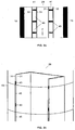
- Figures 2a and 2b show a first embodiment of the invention where the duct 29 inside the tower 13, having a rectangular cross-section, comprises an inner wall 31, an outer wall 33 made of a metal sheet, preferably stainless steel, and an insulating structure 41 arranged between the inner wall 31 and the outer wall 33.
- the treated air flows in the direction indicated by arrow F.
- the insulating structure 41 is formed by a plurality of panels 43 of an insulating material such as glass wool, preferably equally spaced along the duct 29, leaving voids 45 between them.
- the insulating structure 41 shown in Figures 2a and 2b may achieve a reduction of between 40% and 55% of the thermal losses and a reduction of between 85% and 95% of the volume of the insulating material.
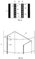
- Figures 3a and 3b show a second embodiment of the invention where the duct 29 inside the tower 13, having a rectangular cross-section, comprises an inner wall 31, an outer wall 33 made of a metal sheet, preferably stainless steel, and an insulating structure 51 arranged between the inner wall 31 and the outer wall 33.
- the treated air flows in the direction indicated by arrow F.
- the insulating structure 51 is formed by a plurality of panels 53 of an insulating material such as glass wool, being alternatively in contact with the inner wall 31 and with the outer wall 33 occupying half the space between the inner wall 31 and the outer wall 31 leaving voids 55 between them.
- the insulating structure 51 shown in Figures 3a and 3b may achieve a reduction of approximately 30% of the thermal losses and a reduction of approximately 50% of the volume of insulating material.
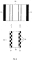
- Figures 4a and 4b show a third embodiment of the invention where the duct 29 inside the tower 13, having a rectangular cross-section, comprises an inner wall 31, an outer wall 33 made of a metal sheet, preferably stainless steel, and an insulating structure 61 arranged between the inner wall 31 and the outer wall 33.
- the insulating structure 61 is formed by a plurality of contiguous insulating blocks 63 occupying the whole space between the inner wall 31 and the outer wall 33.
- Each insulating block has one or more internal voids 65.
- the insulating structure 61 shown in Figures 4a and 4b may achieve a reduction of approximately 25% of the thermal losses and a reduction of approximately 33% of the volume of insulating material.
- Figure 5 illustrates a method for installing the insulating structure 51 in a duct 29 built in vertical sections.
- Single units 50 of the insulating structure 51 for each section of the duct 29 are manufactured arranging the panels 43 inside a thin stiff wrapping 59 according to the above mentioned pattern.
- the single units 50 are inserted between the inner wall 31 and the outer wall of the duct 20.
- the present invention therefore provides an insulating structure for a duct placed inside the tower for supplying treated air to the nacelle structure of an off-shore wind turbine which:
Landscapes
- Engineering & Computer Science (AREA)
- Mechanical Engineering (AREA)
- General Engineering & Computer Science (AREA)
- Life Sciences & Earth Sciences (AREA)
- Sustainable Development (AREA)
- Sustainable Energy (AREA)
- Chemical & Material Sciences (AREA)
- Combustion & Propulsion (AREA)
- Power Engineering (AREA)
- Physics & Mathematics (AREA)
- Thermal Sciences (AREA)
- Wind Motors (AREA)
Applications Claiming Priority (1)
| Application Number | Priority Date | Filing Date | Title |
|---|---|---|---|
| IN735DE2012 IN2012DE00735A (enExample) | 2012-03-14 | 2012-03-14 |
Publications (3)
| Publication Number | Publication Date |
|---|---|
| EP2639451A2 EP2639451A2 (en) | 2013-09-18 |
| EP2639451A3 EP2639451A3 (en) | 2014-12-31 |
| EP2639451B1 true EP2639451B1 (en) | 2016-03-02 |
Family
ID=47844045
Family Applications (1)
| Application Number | Title | Priority Date | Filing Date |
|---|---|---|---|
| EP13001169.5A Active EP2639451B1 (en) | 2012-03-14 | 2013-03-08 | An off-shore wind turbine with a thermal conditioning system |
Country Status (6)
| Country | Link |
|---|---|
| US (1) | US10294964B2 (enExample) |
| EP (1) | EP2639451B1 (enExample) |
| CN (1) | CN103306891B (enExample) |
| BR (1) | BR102013006094A8 (enExample) |
| DK (1) | DK2639451T3 (enExample) |
| IN (1) | IN2012DE00735A (enExample) |
Families Citing this family (1)
| Publication number | Priority date | Publication date | Assignee | Title |
|---|---|---|---|---|
| FR3054522B1 (fr) * | 2016-07-26 | 2019-04-05 | IFP Energies Nouvelles | Support flottant comportant un flotteur et une plaque d'amortissement avec section variable avec la profondeur |
Family Cites Families (12)
| Publication number | Priority date | Publication date | Assignee | Title |
|---|---|---|---|---|
| DE1525658C3 (de) * | 1966-06-01 | 1981-10-15 | Goepfert, Lotte, 2000 Hamburg | Wärmeisoliertes Leitungsrohr |
| GB2021230B (en) * | 1978-04-28 | 1982-05-19 | Nippon Asbestos Co Ltd | Heat insulation systems |
| FR2785967B1 (fr) * | 1998-11-16 | 2000-12-08 | Inst Francais Du Petrole | Conduite isolee thermiquement et methode de farication |
| DE19859628C1 (de) * | 1998-12-23 | 2000-03-23 | Aerodyn Eng Gmbh | Vorrichtung zur Vermeidung des Eindringens von korrosiv wirkenden Salzpartikeln |
| DK1200733T4 (da) * | 1999-07-14 | 2012-04-10 | Aloys Wobben | Vindenergifacilitet med et lukket kølekredsløb |
| DE19947915A1 (de) * | 1999-10-06 | 2001-04-12 | Abb Research Ltd | Kühlsystem für Baugruppen in einer Windkraftanlage |
| ITMI20011458A1 (it) * | 2001-07-09 | 2003-01-09 | Getters Spa | Sistema per l'isolamento termico di corpi tubolari |
| DE102008053814A1 (de) * | 2008-08-06 | 2010-02-11 | Frank Buss | Verfahren und Vorrichtung zur Luftbehandlung in Wind-Energieanlagen |
| JP2011117381A (ja) * | 2009-12-04 | 2011-06-16 | Mitsubishi Heavy Ind Ltd | 風力発電装置 |
| EP2466128B2 (en) * | 2010-12-20 | 2017-06-28 | Siemens Aktiengesellschaft | Wind turbine and method of control of a wind turbine |
| CN202001217U (zh) * | 2011-03-23 | 2011-10-05 | 沈阳中科天道新能源装备股份有限公司 | 一种低温型风力发电机组的空调系统 |
| US8961130B2 (en) * | 2011-06-03 | 2015-02-24 | Gamesa Innovation & Technology, S.L. | Cooling and climate control system and method for an offshore wind turbine |
-
2012
- 2012-03-14 IN IN735DE2012 patent/IN2012DE00735A/en unknown
-
2013
- 2013-03-08 EP EP13001169.5A patent/EP2639451B1/en active Active
- 2013-03-08 DK DK13001169.5T patent/DK2639451T3/en active
- 2013-03-14 BR BR102013006094A patent/BR102013006094A8/pt not_active Application Discontinuation
- 2013-03-14 US US13/826,389 patent/US10294964B2/en active Active
- 2013-03-14 CN CN201310081773.2A patent/CN103306891B/zh active Active
Also Published As
| Publication number | Publication date |
|---|---|
| EP2639451A2 (en) | 2013-09-18 |
| DK2639451T3 (en) | 2016-06-13 |
| BR102013006094A2 (pt) | 2015-06-02 |
| IN2012DE00735A (enExample) | 2015-08-21 |
| BR102013006094A8 (pt) | 2017-10-03 |
| US10294964B2 (en) | 2019-05-21 |
| EP2639451A3 (en) | 2014-12-31 |
| US20130302150A1 (en) | 2013-11-14 |
| CN103306891B (zh) | 2017-11-14 |
| CN103306891A (zh) | 2013-09-18 |
Similar Documents
| Publication | Publication Date | Title |
|---|---|---|
| EP2302214B1 (en) | Method and system for cooling a wind turbine structure | |
| EP2320081B1 (en) | Nacelle cooling system for wind turbine | |
| KR102199299B1 (ko) | 선박 기술을 이용한 전력 발생을 위한 풍력 터빈 | |
| ES2432079T3 (es) | Sistema de generación de potencia que incluye múltiples motores/generadores | |
| JP3715238B2 (ja) | 閉冷却回路を有する風力利用設備 | |
| US20100270804A1 (en) | Air flow turbine | |
| EP2784306B1 (en) | Cooling device for a wind turbine generator | |
| EP2177751A2 (en) | Wind turbine tower foundation containing power and control equipment | |
| CN114667391B (zh) | 风轮机和基于该风轮机的风力发电站 | |
| JP2011117381A (ja) | 風力発電装置 | |
| KR20120065515A (ko) | 풍력과 태양열을 병용한 온수난방장치 | |
| EP2639451B1 (en) | An off-shore wind turbine with a thermal conditioning system | |
| EP2409389B1 (en) | A wind turbine and a direct-drive generator | |
| EP2450570A1 (en) | Cooling arrangement for a wind turbine | |
| WO2013037348A3 (de) | Verfahren zum kontinuierlichen gewinnen von strom, gebäude mit exergie, verfahren zum reduzieren einer stoffbelastung, verfahren zum führen von luft in einem wohngebäude, verfahren zum betreiben einer wärmepumpenanordnung, wärmetauscher und verfahren zum kühlen eines gebäudes, verfahren zum erwärmen von brauchwasser | |
| US20170074248A1 (en) | Wind turbine station and tower with vertical storage tanks | |
| US20090315333A1 (en) | Production of electricity from low-temperature energy sources | |
| KR20150130702A (ko) | 풍량 조절 기능을 겸비한 적층 연동형 풍력발전 시스템 | |
| Wajda et al. | Permanent Magnet Technology within Direct Drive Cooling Tower Motors Creates System Energy Savings | |
| WO2013005090A3 (de) | Windkraftanlage mit vertikaler auftriebskörper - rotationsachse und mit oberflächenveränderlicher luftschraube |
Legal Events
| Date | Code | Title | Description |
|---|---|---|---|
| PUAI | Public reference made under article 153(3) epc to a published international application that has entered the european phase |
Free format text: ORIGINAL CODE: 0009012 |
|
| AK | Designated contracting states |
Kind code of ref document: A2 Designated state(s): AL AT BE BG CH CY CZ DE DK EE ES FI FR GB GR HR HU IE IS IT LI LT LU LV MC MK MT NL NO PL PT RO RS SE SI SK SM TR |
|
| AX | Request for extension of the european patent |
Extension state: BA ME |
|
| PUAL | Search report despatched |
Free format text: ORIGINAL CODE: 0009013 |
|
| AK | Designated contracting states |
Kind code of ref document: A3 Designated state(s): AL AT BE BG CH CY CZ DE DK EE ES FI FR GB GR HR HU IE IS IT LI LT LU LV MC MK MT NL NO PL PT RO RS SE SI SK SM TR |
|
| AX | Request for extension of the european patent |
Extension state: BA ME |
|
| RIC1 | Information provided on ipc code assigned before grant |
Ipc: F03D 11/00 20060101AFI20141127BHEP |
|
| 17P | Request for examination filed |
Effective date: 20150528 |
|
| RBV | Designated contracting states (corrected) |
Designated state(s): AL AT BE BG CH CY CZ DE DK EE ES FI FR GB GR HR HU IE IS IT LI LT LU LV MC MK MT NL NO PL PT RO RS SE SI SK SM TR |
|
| GRAP | Despatch of communication of intention to grant a patent |
Free format text: ORIGINAL CODE: EPIDOSNIGR1 |
|
| INTG | Intention to grant announced |
Effective date: 20150828 |
|
| GRAS | Grant fee paid |
Free format text: ORIGINAL CODE: EPIDOSNIGR3 |
|
| REG | Reference to a national code |
Ref country code: DE Ref legal event code: R079 Ref document number: 602013005197 Country of ref document: DE Free format text: PREVIOUS MAIN CLASS: F03D0011000000 Ipc: F03D0080000000 |
|
| GRAA | (expected) grant |
Free format text: ORIGINAL CODE: 0009210 |
|
| RIC1 | Information provided on ipc code assigned before grant |
Ipc: F03D 80/00 20160101AFI20160107BHEP |
|
| AK | Designated contracting states |
Kind code of ref document: B1 Designated state(s): AL AT BE BG CH CY CZ DE DK EE ES FI FR GB GR HR HU IE IS IT LI LT LU LV MC MK MT NL NO PL PT RO RS SE SI SK SM TR |
|
| REG | Reference to a national code |
Ref country code: GB Ref legal event code: FG4D |
|
| REG | Reference to a national code |
Ref country code: AT Ref legal event code: REF Ref document number: 778244 Country of ref document: AT Kind code of ref document: T Effective date: 20160315 Ref country code: CH Ref legal event code: EP |
|
| REG | Reference to a national code |
Ref country code: IE Ref legal event code: FG4D |
|
| REG | Reference to a national code |
Ref country code: DE Ref legal event code: R096 Ref document number: 602013005197 Country of ref document: DE |
|
| REG | Reference to a national code |
Ref country code: DK Ref legal event code: T3 Effective date: 20160606 |
|
| REG | Reference to a national code |
Ref country code: NL Ref legal event code: FP |
|
| REG | Reference to a national code |
Ref country code: FR Ref legal event code: PLFP Year of fee payment: 4 |
|
| REG | Reference to a national code |
Ref country code: LT Ref legal event code: MG4D |
|
| RAP2 | Party data changed (patent owner data changed or rights of a patent transferred) |
Owner name: ADWEN OFFSHORE, S.L. |
|
| REG | Reference to a national code |
Ref country code: AT Ref legal event code: MK05 Ref document number: 778244 Country of ref document: AT Kind code of ref document: T Effective date: 20160302 |
|
| REG | Reference to a national code |
Ref country code: NO Ref legal event code: T2 Effective date: 20160302 Ref country code: ES Ref legal event code: FG2A Ref document number: 2577702 Country of ref document: ES Kind code of ref document: T3 Effective date: 20160718 |
|
| PG25 | Lapsed in a contracting state [announced via postgrant information from national office to epo] |
Ref country code: FI Free format text: LAPSE BECAUSE OF FAILURE TO SUBMIT A TRANSLATION OF THE DESCRIPTION OR TO PAY THE FEE WITHIN THE PRESCRIBED TIME-LIMIT Effective date: 20160302 Ref country code: GR Free format text: LAPSE BECAUSE OF FAILURE TO SUBMIT A TRANSLATION OF THE DESCRIPTION OR TO PAY THE FEE WITHIN THE PRESCRIBED TIME-LIMIT Effective date: 20160603 Ref country code: HR Free format text: LAPSE BECAUSE OF FAILURE TO SUBMIT A TRANSLATION OF THE DESCRIPTION OR TO PAY THE FEE WITHIN THE PRESCRIBED TIME-LIMIT Effective date: 20160302 |
|
| PG25 | Lapsed in a contracting state [announced via postgrant information from national office to epo] |
Ref country code: LV Free format text: LAPSE BECAUSE OF FAILURE TO SUBMIT A TRANSLATION OF THE DESCRIPTION OR TO PAY THE FEE WITHIN THE PRESCRIBED TIME-LIMIT Effective date: 20160302 Ref country code: SE Free format text: LAPSE BECAUSE OF FAILURE TO SUBMIT A TRANSLATION OF THE DESCRIPTION OR TO PAY THE FEE WITHIN THE PRESCRIBED TIME-LIMIT Effective date: 20160302 Ref country code: PL Free format text: LAPSE BECAUSE OF FAILURE TO SUBMIT A TRANSLATION OF THE DESCRIPTION OR TO PAY THE FEE WITHIN THE PRESCRIBED TIME-LIMIT Effective date: 20160302 Ref country code: LT Free format text: LAPSE BECAUSE OF FAILURE TO SUBMIT A TRANSLATION OF THE DESCRIPTION OR TO PAY THE FEE WITHIN THE PRESCRIBED TIME-LIMIT Effective date: 20160302 Ref country code: RS Free format text: LAPSE BECAUSE OF FAILURE TO SUBMIT A TRANSLATION OF THE DESCRIPTION OR TO PAY THE FEE WITHIN THE PRESCRIBED TIME-LIMIT Effective date: 20160302 Ref country code: AT Free format text: LAPSE BECAUSE OF FAILURE TO SUBMIT A TRANSLATION OF THE DESCRIPTION OR TO PAY THE FEE WITHIN THE PRESCRIBED TIME-LIMIT Effective date: 20160302 |
|
| PG25 | Lapsed in a contracting state [announced via postgrant information from national office to epo] |
Ref country code: IS Free format text: LAPSE BECAUSE OF FAILURE TO SUBMIT A TRANSLATION OF THE DESCRIPTION OR TO PAY THE FEE WITHIN THE PRESCRIBED TIME-LIMIT Effective date: 20160702 Ref country code: EE Free format text: LAPSE BECAUSE OF FAILURE TO SUBMIT A TRANSLATION OF THE DESCRIPTION OR TO PAY THE FEE WITHIN THE PRESCRIBED TIME-LIMIT Effective date: 20160302 |
|
| REG | Reference to a national code |
Ref country code: CH Ref legal event code: PL |
|
| PG25 | Lapsed in a contracting state [announced via postgrant information from national office to epo] |
Ref country code: SK Free format text: LAPSE BECAUSE OF FAILURE TO SUBMIT A TRANSLATION OF THE DESCRIPTION OR TO PAY THE FEE WITHIN THE PRESCRIBED TIME-LIMIT Effective date: 20160302 Ref country code: CZ Free format text: LAPSE BECAUSE OF FAILURE TO SUBMIT A TRANSLATION OF THE DESCRIPTION OR TO PAY THE FEE WITHIN THE PRESCRIBED TIME-LIMIT Effective date: 20160302 Ref country code: RO Free format text: LAPSE BECAUSE OF FAILURE TO SUBMIT A TRANSLATION OF THE DESCRIPTION OR TO PAY THE FEE WITHIN THE PRESCRIBED TIME-LIMIT Effective date: 20160302 Ref country code: PT Free format text: LAPSE BECAUSE OF FAILURE TO SUBMIT A TRANSLATION OF THE DESCRIPTION OR TO PAY THE FEE WITHIN THE PRESCRIBED TIME-LIMIT Effective date: 20160704 Ref country code: SM Free format text: LAPSE BECAUSE OF FAILURE TO SUBMIT A TRANSLATION OF THE DESCRIPTION OR TO PAY THE FEE WITHIN THE PRESCRIBED TIME-LIMIT Effective date: 20160302 |
|
| REG | Reference to a national code |
Ref country code: DE Ref legal event code: R097 Ref document number: 602013005197 Country of ref document: DE |
|
| PG25 | Lapsed in a contracting state [announced via postgrant information from national office to epo] |
Ref country code: IT Free format text: LAPSE BECAUSE OF FAILURE TO SUBMIT A TRANSLATION OF THE DESCRIPTION OR TO PAY THE FEE WITHIN THE PRESCRIBED TIME-LIMIT Effective date: 20160302 |
|
| PLBE | No opposition filed within time limit |
Free format text: ORIGINAL CODE: 0009261 |
|
| STAA | Information on the status of an ep patent application or granted ep patent |
Free format text: STATUS: NO OPPOSITION FILED WITHIN TIME LIMIT |
|
| PG25 | Lapsed in a contracting state [announced via postgrant information from national office to epo] |
Ref country code: CH Free format text: LAPSE BECAUSE OF NON-PAYMENT OF DUE FEES Effective date: 20160331 Ref country code: LI Free format text: LAPSE BECAUSE OF NON-PAYMENT OF DUE FEES Effective date: 20160331 |
|
| 26N | No opposition filed |
Effective date: 20161205 |
|
| REG | Reference to a national code |
Ref country code: FR Ref legal event code: PLFP Year of fee payment: 5 |
|
| PG25 | Lapsed in a contracting state [announced via postgrant information from national office to epo] |
Ref country code: SI Free format text: LAPSE BECAUSE OF FAILURE TO SUBMIT A TRANSLATION OF THE DESCRIPTION OR TO PAY THE FEE WITHIN THE PRESCRIBED TIME-LIMIT Effective date: 20160302 Ref country code: BG Free format text: LAPSE BECAUSE OF FAILURE TO SUBMIT A TRANSLATION OF THE DESCRIPTION OR TO PAY THE FEE WITHIN THE PRESCRIBED TIME-LIMIT Effective date: 20160602 |
|
| PG25 | Lapsed in a contracting state [announced via postgrant information from national office to epo] |
Ref country code: MT Free format text: LAPSE BECAUSE OF FAILURE TO SUBMIT A TRANSLATION OF THE DESCRIPTION OR TO PAY THE FEE WITHIN THE PRESCRIBED TIME-LIMIT Effective date: 20160302 |
|
| REG | Reference to a national code |
Ref country code: FR Ref legal event code: PLFP Year of fee payment: 6 |
|
| PG25 | Lapsed in a contracting state [announced via postgrant information from national office to epo] |
Ref country code: HU Free format text: LAPSE BECAUSE OF FAILURE TO SUBMIT A TRANSLATION OF THE DESCRIPTION OR TO PAY THE FEE WITHIN THE PRESCRIBED TIME-LIMIT; INVALID AB INITIO Effective date: 20130308 Ref country code: CY Free format text: LAPSE BECAUSE OF FAILURE TO SUBMIT A TRANSLATION OF THE DESCRIPTION OR TO PAY THE FEE WITHIN THE PRESCRIBED TIME-LIMIT Effective date: 20160302 |
|
| PG25 | Lapsed in a contracting state [announced via postgrant information from national office to epo] |
Ref country code: LU Free format text: LAPSE BECAUSE OF NON-PAYMENT OF DUE FEES Effective date: 20160308 Ref country code: MT Free format text: LAPSE BECAUSE OF FAILURE TO SUBMIT A TRANSLATION OF THE DESCRIPTION OR TO PAY THE FEE WITHIN THE PRESCRIBED TIME-LIMIT Effective date: 20160331 Ref country code: MC Free format text: LAPSE BECAUSE OF FAILURE TO SUBMIT A TRANSLATION OF THE DESCRIPTION OR TO PAY THE FEE WITHIN THE PRESCRIBED TIME-LIMIT Effective date: 20160302 Ref country code: TR Free format text: LAPSE BECAUSE OF FAILURE TO SUBMIT A TRANSLATION OF THE DESCRIPTION OR TO PAY THE FEE WITHIN THE PRESCRIBED TIME-LIMIT Effective date: 20160302 Ref country code: MK Free format text: LAPSE BECAUSE OF FAILURE TO SUBMIT A TRANSLATION OF THE DESCRIPTION OR TO PAY THE FEE WITHIN THE PRESCRIBED TIME-LIMIT Effective date: 20160302 |
|
| PG25 | Lapsed in a contracting state [announced via postgrant information from national office to epo] |
Ref country code: AL Free format text: LAPSE BECAUSE OF FAILURE TO SUBMIT A TRANSLATION OF THE DESCRIPTION OR TO PAY THE FEE WITHIN THE PRESCRIBED TIME-LIMIT Effective date: 20160302 |
|
| REG | Reference to a national code |
Ref country code: DE Ref legal event code: R082 Ref document number: 602013005197 Country of ref document: DE Ref country code: DE Ref legal event code: R081 Ref document number: 602013005197 Country of ref document: DE Owner name: SIEMENS GAMESA RENEWABLE ENERGY INNOVATION & T, ES Free format text: FORMER OWNER: GAMESA INNOVATION & TECHNOLOGY, S.L., SARRIGUREN, ES |
|
| PGFP | Annual fee paid to national office [announced via postgrant information from national office to epo] |
Ref country code: DE Payment date: 20250327 Year of fee payment: 13 |
|
| PGFP | Annual fee paid to national office [announced via postgrant information from national office to epo] |
Ref country code: DK Payment date: 20250325 Year of fee payment: 13 Ref country code: NL Payment date: 20250325 Year of fee payment: 13 |
|
| PGFP | Annual fee paid to national office [announced via postgrant information from national office to epo] |
Ref country code: IE Payment date: 20250318 Year of fee payment: 13 |
|
| PGFP | Annual fee paid to national office [announced via postgrant information from national office to epo] |
Ref country code: NO Payment date: 20250319 Year of fee payment: 13 |
|
| PGFP | Annual fee paid to national office [announced via postgrant information from national office to epo] |
Ref country code: BE Payment date: 20250325 Year of fee payment: 13 |
|
| PGFP | Annual fee paid to national office [announced via postgrant information from national office to epo] |
Ref country code: FR Payment date: 20250324 Year of fee payment: 13 |
|
| PGFP | Annual fee paid to national office [announced via postgrant information from national office to epo] |
Ref country code: GB Payment date: 20250325 Year of fee payment: 13 |
|
| PGFP | Annual fee paid to national office [announced via postgrant information from national office to epo] |
Ref country code: ES Payment date: 20250417 Year of fee payment: 13 |