EP2638353B1 - Vorrichtung und verfahren zum definierten beschleunigen eines projektils - Google Patents
Vorrichtung und verfahren zum definierten beschleunigen eines projektils Download PDFInfo
- Publication number
- EP2638353B1 EP2638353B1 EP11778840.6A EP11778840A EP2638353B1 EP 2638353 B1 EP2638353 B1 EP 2638353B1 EP 11778840 A EP11778840 A EP 11778840A EP 2638353 B1 EP2638353 B1 EP 2638353B1
- Authority
- EP
- European Patent Office
- Prior art keywords
- projectile
- adjusting
- chamber
- spring
- cylinder
- Prior art date
- Legal status (The legal status is an assumption and is not a legal conclusion. Google has not performed a legal analysis and makes no representation as to the accuracy of the status listed.)
- Not-in-force
Links
- 230000001133 acceleration Effects 0.000 title claims description 10
- 238000000034 method Methods 0.000 title claims description 6
- 239000011521 glass Substances 0.000 claims description 25
- 238000012360 testing method Methods 0.000 claims description 18
- 229920000515 polycarbonate Polymers 0.000 claims description 16
- 239000004417 polycarbonate Substances 0.000 claims description 16
- -1 polyethylene Polymers 0.000 claims description 16
- XEEYBQQBJWHFJM-UHFFFAOYSA-N Iron Chemical compound [Fe] XEEYBQQBJWHFJM-UHFFFAOYSA-N 0.000 claims description 8
- PXHVJJICTQNCMI-UHFFFAOYSA-N Nickel Chemical compound [Ni] PXHVJJICTQNCMI-UHFFFAOYSA-N 0.000 claims description 8
- 239000000203 mixture Substances 0.000 claims description 8
- 229920000139 polyethylene terephthalate Polymers 0.000 claims description 8
- 239000005020 polyethylene terephthalate Substances 0.000 claims description 8
- VYZAMTAEIAYCRO-UHFFFAOYSA-N Chromium Chemical compound [Cr] VYZAMTAEIAYCRO-UHFFFAOYSA-N 0.000 claims description 4
- 239000004952 Polyamide Substances 0.000 claims description 4
- 239000004698 Polyethylene Substances 0.000 claims description 4
- 239000004743 Polypropylene Substances 0.000 claims description 4
- 239000004793 Polystyrene Substances 0.000 claims description 4
- RTAQQCXQSZGOHL-UHFFFAOYSA-N Titanium Chemical compound [Ti] RTAQQCXQSZGOHL-UHFFFAOYSA-N 0.000 claims description 4
- XECAHXYUAAWDEL-UHFFFAOYSA-N acrylonitrile butadiene styrene Chemical compound C=CC=C.C=CC#N.C=CC1=CC=CC=C1 XECAHXYUAAWDEL-UHFFFAOYSA-N 0.000 claims description 4
- 229920000122 acrylonitrile butadiene styrene Polymers 0.000 claims description 4
- 239000004676 acrylonitrile butadiene styrene Substances 0.000 claims description 4
- 239000000956 alloy Substances 0.000 claims description 4
- 229910045601 alloy Inorganic materials 0.000 claims description 4
- 229910052782 aluminium Inorganic materials 0.000 claims description 4
- XAGFODPZIPBFFR-UHFFFAOYSA-N aluminium Chemical compound [Al] XAGFODPZIPBFFR-UHFFFAOYSA-N 0.000 claims description 4
- 229910052804 chromium Inorganic materials 0.000 claims description 4
- 239000011651 chromium Substances 0.000 claims description 4
- 229910017052 cobalt Inorganic materials 0.000 claims description 4
- 239000010941 cobalt Substances 0.000 claims description 4
- GUTLYIVDDKVIGB-UHFFFAOYSA-N cobalt atom Chemical compound [Co] GUTLYIVDDKVIGB-UHFFFAOYSA-N 0.000 claims description 4
- 229920001577 copolymer Polymers 0.000 claims description 4
- 229910052742 iron Inorganic materials 0.000 claims description 4
- 229910052751 metal Inorganic materials 0.000 claims description 4
- 239000002184 metal Substances 0.000 claims description 4
- 229910052759 nickel Inorganic materials 0.000 claims description 4
- 229920000058 polyacrylate Polymers 0.000 claims description 4
- 229920002647 polyamide Polymers 0.000 claims description 4
- 229920001707 polybutylene terephthalate Polymers 0.000 claims description 4
- 229920000728 polyester Polymers 0.000 claims description 4
- 229920000573 polyethylene Polymers 0.000 claims description 4
- 229920000642 polymer Polymers 0.000 claims description 4
- 229920001155 polypropylene Polymers 0.000 claims description 4
- 229920002223 polystyrene Polymers 0.000 claims description 4
- 229920002635 polyurethane Polymers 0.000 claims description 4
- 239000004814 polyurethane Substances 0.000 claims description 4
- 239000010936 titanium Substances 0.000 claims description 4
- 229910052719 titanium Inorganic materials 0.000 claims description 4
- WFKWXMTUELFFGS-UHFFFAOYSA-N tungsten Chemical compound [W] WFKWXMTUELFFGS-UHFFFAOYSA-N 0.000 claims description 4
- 229910052721 tungsten Inorganic materials 0.000 claims description 4
- 239000010937 tungsten Substances 0.000 claims description 4
- 229910052720 vanadium Inorganic materials 0.000 claims description 4
- LEONUFNNVUYDNQ-UHFFFAOYSA-N vanadium atom Chemical compound [V] LEONUFNNVUYDNQ-UHFFFAOYSA-N 0.000 claims description 4
- 239000004411 aluminium Substances 0.000 claims 2
- 238000006073 displacement reaction Methods 0.000 description 3
- 239000004575 stone Substances 0.000 description 3
- LYCAIKOWRPUZTN-UHFFFAOYSA-N Ethylene glycol Chemical compound OCCO LYCAIKOWRPUZTN-UHFFFAOYSA-N 0.000 description 2
- 230000004888 barrier function Effects 0.000 description 2
- 239000000463 material Substances 0.000 description 2
- 229920003229 poly(methyl methacrylate) Polymers 0.000 description 2
- 230000005483 Hooke's law Effects 0.000 description 1
- 229910000831 Steel Inorganic materials 0.000 description 1
- 238000004364 calculation method Methods 0.000 description 1
- 239000011248 coating agent Substances 0.000 description 1
- 238000000576 coating method Methods 0.000 description 1
- 230000001419 dependent effect Effects 0.000 description 1
- 229920001971 elastomer Polymers 0.000 description 1
- 238000002474 experimental method Methods 0.000 description 1
- 210000003746 feather Anatomy 0.000 description 1
- WGCNASOHLSPBMP-UHFFFAOYSA-N hydroxyacetaldehyde Natural products OCC=O WGCNASOHLSPBMP-UHFFFAOYSA-N 0.000 description 1
- 238000007373 indentation Methods 0.000 description 1
- 238000005259 measurement Methods 0.000 description 1
- 239000012286 potassium permanganate Substances 0.000 description 1
- 238000005381 potential energy Methods 0.000 description 1
- 230000001681 protective effect Effects 0.000 description 1
- 230000003763 resistance to breakage Effects 0.000 description 1
- 230000000717 retained effect Effects 0.000 description 1
- 239000005060 rubber Substances 0.000 description 1
- 239000005336 safety glass Substances 0.000 description 1
- 239000010959 steel Substances 0.000 description 1
- 238000010998 test method Methods 0.000 description 1
Images


Classifications
-
- F—MECHANICAL ENGINEERING; LIGHTING; HEATING; WEAPONS; BLASTING
- F41—WEAPONS
- F41B—WEAPONS FOR PROJECTING MISSILES WITHOUT USE OF EXPLOSIVE OR COMBUSTIBLE PROPELLANT CHARGE; WEAPONS NOT OTHERWISE PROVIDED FOR
- F41B7/00—Spring guns
-
- G—PHYSICS
- G01—MEASURING; TESTING
- G01N—INVESTIGATING OR ANALYSING MATERIALS BY DETERMINING THEIR CHEMICAL OR PHYSICAL PROPERTIES
- G01N3/00—Investigating strength properties of solid materials by application of mechanical stress
- G01N3/30—Investigating strength properties of solid materials by application of mechanical stress by applying a single impulsive force, e.g. by falling weight
- G01N3/307—Investigating strength properties of solid materials by application of mechanical stress by applying a single impulsive force, e.g. by falling weight generated by a compressed or tensile-stressed spring; generated by pneumatic or hydraulic means
Definitions
- the invention relates to a device for the defined acceleration of a projectile and their use.
- glass is often a brittle and often fragile material. In many cases, glass is used in safety-related areas. To test the material properties, in particular the resistance of glass, a variety of test methods are used. An important criterion can be, for example, the stability of a glass pane against small objects that hit it. These can be small stones that hit the windscreen of a vehicle, airplane or train while driving. Depending on their weight and airspeed, this can result in greater damage or a broken disc.
- the stability of a disc is usually checked by means of ball drop tests. For this purpose, steel balls with known diameters and weights from a known height are dropped onto a disc. From the resulting fracture pattern or the absence of such, can draw conclusions about the stability of the disc. These simple ball drop tests, however, can not be transferred to all possible dangerous situations. In particular, in the mentioned rockfall stones often have a high speed and thus high kinetic energy. The energy released upon impact often causes serious damage to the disc.
- DE 36 07 738 C1 discloses a device for repairing windshields made of multilayer safety glass.
- US2002014778 A1 discloses a method for protecting windshields of a motor vehicle against stone chipping.
- the protective effect is generated by a resistant barrier in the edge region of the disc.
- GB552544 A discloses an apparatus for testing glass bottles.
- the device allows movement of the bottle in defined paths and the release of weights on the glass bottle to be tested.
- US2006 / 0169263 A1 discloses an apparatus for launching projectiles, in particular fire-generating projectiles of potassium permanganate and a glycol for controlling forest fires.
- the object of the invention is to provide a device and a method which enables a reproducible bombardment of a glass pane with a suitable test projectile.
- the device according to the invention for the defined acceleration of a projectile comprises at least one hollow body.
- the hollow body may be made of a workpiece or composed of several workpieces.
- the cavity located in the hollow body is formed by a continuously connected adjusting chamber and a projectile chamber.
- the adjustment chamber and the Projectile chamber are connected to each other throughout and each have preferably circular, diameter.
- the diameter of the projectile chamber is preferably at least 30% smaller than the diameter of the adjustment chamber.
- the adjustment chamber contains an adjustment cylinder with an end piece and an adjusting screw attached to the end piece with screw thread. With the aid of the adjusting screw, the position of the adjusting cylinder in the adjusting chamber can be varied along the imaginary central axis running within the cavity.
- the adjustment cylinder contains a movably arranged adjustment block.
- the projectile chamber connected to the adjustment chamber contains a projectile mount with projectile and a cavity stopper that is permeable only to the projectile but not to the projectile mount.
- the projectile holder and the adjustment block are connected by a mechanical spring tensioned.
- the spring moves from the cocked condition to the relaxed condition.
- the released potential energy causes an acceleration of the projectile mount and the projectile therein.
- the projectile can leave the projectile chamber and the hollow body opposite to the adjustment chamber, while the projectile holder is retained at the stopper.
- the stopper thus prevents complete relaxation of the spring or coil located between the projectile holder and the adjustment cylinder fixed by adjustment.
- the contact surfaces between the projectile holder and the inner wall of the projectile chamber preferably contain a coating of a low-viscosity oil, preferably less than 10 mPa * s.
- the adjustment chamber, the projectile chamber, adjustment cylinder and the adjustment block preferably have a circular cross-section in diameter. The device according to the invention allows a constant kinetic energy of the projectile in all test series.
- the adjustment block preferably comprises a handle attached to the adjustment block.
- the hollow body, the adjusting chamber and the adjusting cylinder preferably contain a slot-shaped opening, which allows a displacement of the adjustment block on the adjustment block attached to the handle from outside the hollow body.
- the adjustment cylinder preferably has a slot and notches connected to the slot.
- the indentations allow the fixing block to be fixed attached handle.
- the notches can be used to define the position of the adjustment block within the adjustment cylinder.
- the hollow body, adjusting cylinder and / or adjusting block preferably contain a metal, preferably aluminum, titanium, iron, chromium, vanadium, cobalt, nickel, tungsten and / or alloys thereof.
- the hollow body is composed of two half-opened bodies.
- the hollow body or alignment block preferably contains a polymer, preferably polyethylene, polypropylene, polystyrene, polyurethanes, polymethyl methacrylates, polyacrylates, polyesters, polyamides, polyethylene terephthalate and / or mixtures or copolymers thereof, more preferably polycarbonate blends such as polycarbonate / polyethylene terephthalate; Polycarbonate / acrylonitrile-butadiene-styrene; Polycarbonate / polybutylene terephthalate.
- a polymer preferably polyethylene, polypropylene, polystyrene, polyurethanes, polymethyl methacrylates, polyacrylates, polyesters, polyamides, polyethylene terephthalate and / or mixtures or copolymers thereof, more preferably polycarbonate blends such as polycarbonate / polyethylene terephthalate; Polycarbonate / acrylonitrile-butadiene-styrene; Polycarbonate / polybut
- the spring preferably contains a metal, particularly preferably aluminum, titanium, iron, chromium, vanadium, cobalt, nickel, tungsten and / or alloys thereof, and particularly preferably piano wire.
- the spring preferably has a spring constant of a value of 5 N / m to 100 N / m, preferably 10 N / m to 50 N / m.
- the projectile holder, the stopper and the relief pin preferably contain a polymer, particularly preferably polyethylene, polypropylene, polystyrene, polyurethanes, polymethylmethacrylates, polyacrylates, polyesters, polyamides, polyethylene terephthalate and / or mixtures or copolymers thereof, particularly preferably polycarbonate blends such as polycarbonate / polyethylene terephthalate; Polycarbonate / acrylonitrile-butadiene-styrene; Polycarbonate / polybutylene terephthalate.
- a polymer particularly preferably polyethylene, polypropylene, polystyrene, polyurethanes, polymethylmethacrylates, polyacrylates, polyesters, polyamides, polyethylene terephthalate and / or mixtures or copolymers thereof, particularly preferably polycarbonate blends such as polycarbonate / polyethylene terephthalate; Polycarbonate / acrylonitrile-butadiene-styren
- the adjustment chamber preferably has a diameter of 0.2 cm to 10 cm, more preferably from 0.5 cm to 5 cm.
- the projectile chamber preferably has a diameter of 0.1 cm to 3 cm, more preferably from 0.5 cm to 2 cm.
- the projectile preferably has a conical, cylindrical or spherical base body.
- the shape of the base body preferably corresponds to the shape of the interior of the projectile chamber.
- the projectile preferably has a weight of 1 g to 10 g, preferably 2 g to 5 g.
- the invention further includes a device for testing the resistance to breakage of glass.
- a device for testing the resistance to breakage of glass for this purpose, as described above, a device made of hollow body with a cavity in the cavity, continuously connected adjusting chamber and projectile chamber is clamped in a stand via a tripod attachment. Perpendicular to the device, the disc to be examined is placed. The disc is preferably fixed via disc holders. After loosening the locking pin the projectile flies with defined and reproducible kinetic energy on the disk to be tested.
- the device according to the invention is portable used for the defined bombardment of a disc.
- the device preferably includes a hand-grip handle.
- the invention further includes a method for glass breakage testing and bombardment of glass with projectiles of defined kinetic energy.
- the device according to the invention is aligned with a glass pane, preferably at a distance of 1 mm to 5 mm from the glass pane.
- the alignment is preferably done by hand.
- a voltage and thus energy in the spring are preset via the position of the adjustment cylinder and adjustment block.
- the set energy is transferred to the projectile and the projectile is transported onto the glass with defined energy.
- the invention further includes the use of the device for the defined bombardment of glass, preferably as a glass breakage test.
- the device for the defined bombardment of glass preferably as a glass breakage test.
- FIG. 1 shows a cross section of the device (I) according to the invention.
- the adjusting chamber (12) contains an adjusting cylinder (4) with an end piece (2) and an adjusting screw (1) with screw thread (11) attached to the end piece (2). With the aid of the adjusting screw (1), the position of the adjusting cylinder (4) in the adjusting chamber (12) along the inside of the cavity extending imaginary central axis vary.
- the adjustment cylinder (4) contains a movably arranged adjustment block (5).
- the adjustment block (5) comprises a on the adjustment block (5) attached, not shown, handle (5a).
- the projectile chamber (10) connected to the adjustment chamber (12) contains a projectile holder (7) with projectile (8) and a stopper (9) with a cavity which is permeable only to the projectile (8) but not to the projectile holder (7) ,
- the projectile holder (7) and the Justageblock (5) are connected by a spring (6) tensioned.
- Adjacent to the projectile holder (7) is a movable relief pin (13). If the relief pin (13) is removed, the relaxed Spring (6) and passes the energy released to the projectile holder (7) and the projectile (8) on.
- FIG. 2 shows a schematic representation of a preferred embodiment of the adjustment cylinder (4).
- the adjustment block (5) preferably has a cylindrical shape and preferably comprises a handle (5a) attached to the adjustment block (5).
- the adjustment cylinder (4) has a slot (4b), which from outside the adjustment cylinder (4) allows a displacement of the adjustment block (5) via the adjusting block (5) fixed handle (5a).
- the adjustment cylinder (4) has notches (4a) connected to the slot (4b). The notches (4a) allow a fixation of the adjustment block (5) attached to the handle (5a). About the notches (4a), the position of the Justageblocks (5) within the Justagezylinders (4) set. The position of the adjustment block (5) controls the expansion of the spring (6) and thus the force acting on the projectile holder (7).
- FIG. 3 shows a cross section of the device according to the invention with tensioned spring (I) in comparison with a cross section of the device according to the invention with a relaxed spring (II).
- the structure of the device (I, II) according to the invention corresponds to the in FIG. 1 described.
- the device (I) shows the tensioned spring (6) as length B
- the device (II) shows the relaxed spring (6) as length B '.
- the length B ' is greater than B in the tensioned spring device (I) (6).
- the lengths A and A ' shown indicate the displacement of the adjustment cylinder (4) within the adjustment chamber (12).
- the force transmitted to the spring (6) results from the position of the adjustment block (5) and thus the length B / B 'and the position of the adjustment cylinder (4) within the adjustment chamber (12) over the length A / A'.
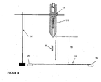
- FIG. 4 shows a schematic representation of the apparatus according to the invention for testing the fracture resistance of glass sheets.
- a device (I, II) according to the invention is clamped in a stand (16) via a stand attachment (17). Perpendicular to the device (I, II) is placed to be examined disc (14).
- the disc (14) is preferably fixed via disc holders (15). After releasing the unloading pin (13) not shown, the projectile (8) flies over a defined distance (18) with defined and reproducible kinetic energy to the disk (14) to be tested.
Landscapes
- Physics & Mathematics (AREA)
- Health & Medical Sciences (AREA)
- Life Sciences & Earth Sciences (AREA)
- Chemical & Material Sciences (AREA)
- Analytical Chemistry (AREA)
- Biochemistry (AREA)
- General Health & Medical Sciences (AREA)
- General Physics & Mathematics (AREA)
- Immunology (AREA)
- Pathology (AREA)
- Engineering & Computer Science (AREA)
- General Engineering & Computer Science (AREA)
- Investigating Strength Of Materials By Application Of Mechanical Stress (AREA)
Description
- Die Erfindung betrifft eine Vorrichtung zum definierten Beschleunigen eines Projektils und deren Verwendung.
- Trotz seiner hohen Oberflächenhärte ist Glas ein oft spröder und häufig leicht zerbrechlicher Werkstoff. In vielen Fällen wird Glas jedoch in sicherheitsrelevanten Bereichen eingesetzt. Zum Überprüfen der Materialeigenschaften, insbesondere der Beständigkeit von Glas kommen eine Vielzahl von Testverfahren zum Einsatz. Ein wichtiges Kriterium kann beispielsweise die Stabilität einer Glasscheibe gegenüber auftreffenden kleinen Gegenständen sein. Dies können kleine Steine sein, die während der Fahrt auf die Windschutzscheibe eines Fahrzeuges, Flugzeuges oder Eisenbahn treffen. In Abhängigkeit von ihrem Gewicht und der Eigengeschwindigkeit können daraus größere Schäden oder eine zerbrochene Scheibe resultieren. Die Stabilität einer Scheibe wird in der Regel mit Hilfe von Kugelfalltests überprüft. Hierzu werden Stahlkugeln mit bekannten Durchmessern und Gewichten aus einer bekannten Höhe auf eine Scheibe fallen gelassen. Aus dem entstehenden Bruchbild oder auch der Abwesenheit eines solchen, lassen sich Rückschlüsse auf die Stabilität der Scheibe ziehen. Diese einfachen Kugelfalltests lassen sich jedoch nicht auf alle möglichen Gefahrensituationen übertragen. Insbesondere bei dem genannten Steinschlag weisen die Steine häufig eine hohe Geschwindigkeit und damit hohe kinetische Energie auf. Die beim Aufprall freiwerdende Energie bewirkt häufig eine ernsthafte Beschädigung der Scheibe.
- Eine Abschätzung der Stabilität und Beständigkeit einer Scheibe lässt sich jedoch nur bei genau definierten Versuchsbedingungen vornehmen. Insbesondere die Abschätzung der Geschwindigkeit und Beschleunigung des Testprojektils ist in der Praxis häufig sehr schwierig. Aufgrund des niedrigen Eigengewichtes des Projektils reichen einfache Kugelfallexperimente nicht aus, um die erforderliche Geschwindigkeit und kinetische Energie beim Aufprall bereitzustellen. Das Projektil muss durch weitere mechanische Elemente wie Spiralen oder Gummis beschleunigt werden. Auch in diesen Fällen ist eine genaue und reproduzierbare Einstellung der kinetischen Energie des Projektils schwierig. Durch den Einsatz von Lichtschranken oder CCD-Kameras lässt sich zwar die Geschwindigkeit und damit die kinetische Energie eines Projektils recht genau bestimmen. In vielen Fällen weichen die Ergebnisse der kinetischen Energie jedoch zwischen den einzelnen Messungen stark voneinander ab.
-
DE 36 07 738 C1 offenbart eine Einrichtung zum Ausbessern von Windschutzscheiben aus mehrschichtigen Sicherheitsglas. -
US2002014778 A1 offenbart ein Verfahren zum Schutz von Windschutzscheiben eines Kraftfahrzeuges vor Steinschlag. Die Schutzwirkung wird durch eine resistente Barriere im Randbereich der Scheibe erzeugt. -
GB552544 A -
US2006/0169263 A1 offenbart eine Vorrichtung zum Abschuss von Projektilen, insbesondere branderzeugende Projektile aus Kaliumpermanganat und einem Glykol zur Bekämpfung von Waldbränden. - Die Aufgabe der Erfindung liegt darin, eine Vorrichtung und ein Verfahren bereitzustellen, welche einen reproduzierbaren Beschuss einer Glasscheibe mit einem geeigneten Testprojektil ermöglicht.
- Die Aufgabe der vorliegenden Erfindung wird erfindungsgemäß durch den unabhängigen Anspruch 1 gelöst. Bevorzugte Ausführungen gehen aus den Unteransprüchen hervor.
- Ein erfindungsgemäßes Verfahren zur Glasbruchprüfung und die erfindungsgemäße Verwendung der Vorrichtung gehen aus weiteren nebengeordneten Ansprüchen hervor.
- Die erfindungsgemäße Vorrichtung zum definierten Beschleunigen eines Projektils umfasst mindestens einen Hohlkörper. Der Hohlkörper kann aus einem Werkstück gefertigt sein oder aus mehren Werkstücken zusammengesetzt sein. Der im Hohlkörper befindliche Hohlraum wird von einer durchgehend verbundenen Justierkammer und einer Projektilkammer gebildet. Die Justierkammer und die Projektilkammer sind durchgehend miteinander verbunden und weisen jeweils bevorzugt kreisförmigen, Durchmesser auf. Der Durchmesser der Projektilkammer ist bevorzugt mindestens 30 % kleiner als der Durchmesser der Justierkammer. Die Justierkammer enthält einen Justagezylinder mit einem Endstück und einer am Endstück befestigten Justierschraube mit Schraubgewinde. Mit Hilfe der Justierschraube lässt sich die Position des Justagezylinders in der Justierkammer entlang der innerhalb des Hohlraums verlaufenden gedachten Mittelachse variieren. Der Justagezylinder enthält einen beweglich angeordneten Justageblock. Die mit der Justierkammer verbundene Projektilkammer enthält eine Projektilhalterung mit Projektil sowie einen Stopper mit Hohlraum der nur für das Projektil aber nicht für die Projektilhalterung durchlässig ist. Die Projektilhalterung und der Justageblock sind durch eine mechanische Feder gespannt verbunden. Sobald der an der Projektilhalterung befindliche, bewegliche Entlastungsstift entfernt ist, geht die Feder vom gespannten Zustand in den entspannten Zustand über. Die dabei freiwerdende potentielle Energie bewirkt eine Beschleunigung der Projektilhalterung und des darin befindlichen Projektils. Das Projektil kann die Projektilkammer und den Hohlkörper entgegengesetzt zur Justierkammer verlassen, während der Projektilhalter am Stopper zurückgehalten wird. Der Stopper verhindert somit eine vollständige Entspannung der zwischen der Projektilhalterung und der durch Einstellung fixierten Justagezylinders befindlichen Feder oder Spirale. Die Kontaktflächen zwischen der Projektilhalterung und der Innenwand der Projektilkammer enthalten bevorzugt eine Beschichtung eines niedrigviskosen Öls, bevorzugt kleiner als 10 mPa*s. Die Justierkammer, die Projektilkammer, Justagezylinder und der Justageblock weisen bevorzugt einen im Querschnitt kreisförmigen Durchmesser auf. Die erfindungsgemäße Vorrichtung ermöglicht eine konstante kinetische Energie des Projektils bei allen Untersuchungsreihen.
- Der Justageblock umfasst bevorzugt einen am Justageblock befestigten Griff. Der Hohlkörper, die Justierkammer und der Justagezylinder enthalten bevorzugt eine schlitzförmige Öffnung, welche von außerhalb des Hohlkörpers ein Verschieben des Justageblocks über den am Justageblock befestigten Griff ermöglicht.
- Der Justagezylinder weist bevorzugt einen Schlitz und mit dem Schlitz verbundene Einkerbungen auf. Die Einkerbungen ermöglichen ein fixieren des am Justageblocks befestigten Griffs. Über die Einkerbungen lässt sich die Position des Justageblocks innerhalb des Justagezylinders festlegen.
- Der Hohlkörper, Justagezylinder und/oder Justageblock enthalten bevorzugt ein Metall, bevorzugt Aluminium, Titan, Eisen, Chrom, Vanadium, Kobalt, Nickel, Wolfram und/oder Legierungen davon. In einer alternativen Ausgestaltung ist der Hohlkörper aus zwei halbgeöffneten Körpern zusammengesetzt.
- Der Hohlkörper oder Justageblock enthalten bevorzugt ein Polymer, bevorzugt Polyethylen, Polypropylen, Polystyrol, Polyurethane, Polymethylmetacrylate, Polyacrylate, Polyester, Polyamide, Polyethylenterephthalat und/oder Gemische oder Copolymere davon, besonders bevorzugt Polycarbonatblends wie Polycarbonat/Polyethylenterephthalat; Polycarbonat/Acrylnitril-Butadien-Styrol; Polycarbonat/Polybutylenterephthalat.
- Die Feder enthält bevorzugt ein Metall, besonders bevorzugt Aluminium, Titan, Eisen, Chrom, Vanadium, Kobalt, Nickel, Wolfram und/oder Legierungen davon, sowie insbesondere bevorzugt Klavierdraht.
- Die Feder weist bevorzugt eine Federkonstante einen Wert von 5 N/m bis 100 N/m, bevorzugt 10 N/m bis 50 N/m, auf. Über unterschiedliche Federn mit entsprechenden Federkonstanten lässt sich die auf das Projektil wirkende Kraft weiter einstellen. Die Feder überträgt gemäß dem Hook'schen Gesetz eine Kraft F = -kΔX, wobei k der Federkonstanten und ΔX der Auslenkung aus der Gleichgewichtslage entsprechen. Das Hook'sche Gesetz erlaubt insbesondere bei kleineren Auslenkungen der Feder eine recht präzise Berechnung der auf das Projektil wirkenden Kraft.
- Die Projektilhalterung, der Stopper und der Entlastungsstift enthalten bevorzugt ein Polymer, besonders bevorzugt Polyethylen, Polypropylen, Polystyrol, Polyurethane, Polymethylmetacrylate, Polyacrylate, Polyester, Polyamide, Polyethylenterephthalat und/oder Gemische oder Copolymere davon, insbesondere bevorzugt Polycarbonatblends wie Polycarbonat/Polyethylenterephthalat; Polycarbonat/Acrylnitril-Butadien-Styrol; Polycarbonat/Polybutylenterephthalat.
- Die Justierkammer weist bevorzugt einen Durchmesser von 0,2 cm bis 10 cm, besonders bevorzugt von 0,5 cm bis 5 cm auf.
- Die Projektilkammer weist bevorzugt einen Durchmesser von 0,1 cm bis 3 cm, besonders bevorzugt von 0,5 cm bis 2 cm auf.
- Das Projektil weist bevorzugt einen konischen, zylinderförmigen oder kugelförmigen Grundkörper auf. Die Form des Grundkörpers entspricht bevorzugt der Form des Innenraums der Projektilkammer.
- Das Projektil weist bevorzugt ein Gewicht von 1 g bis 10 g, bevorzugt 2 g bis 5 g auf.
- Die Erfindung umfasst des Weiteren eine Vorrichtung zum Testen der Bruchbeständigkeit von Glas. Dazu wird eine wie oben beschriebene Vorrichtung aus Hohlkörper mit im Hohlraum befindlichen, durchgehend verbundenen Justierkammer und Projektilkammer in ein Stativ über eine Stativbefestigung eingespannt. Senkrecht zur Vorrichtung wird die zu untersuchende Scheibe platziert. Die Scheibe wird bevorzugt über Scheibenhalterungen fixiert. Nach Lösen des Sicherungsstiftes fliegt das Projektil mit definierter und reproduzierbarer kinetischer Energie auf die zu testende Scheibe.
- In einer alternativen Ausführungsform wird die erfindungsgemäße Vorrichtung tragbar zum definierten Beschuss einer Scheibe verwendet. Die Vorrichtung enthält bevorzugt einen Handtragegriff.
- Die Erfindung umfasst des Weiteren ein Verfahren zur Glasbruchprüfung und zum Beschuss von Glas mit Projektilen definierter kinetischer Energie. Dazu wird die erfindungsgemäße Vorrichtung auf eine Glasscheibe ausgerichtet, bevorzugt in einem Abstand von 1 mm bis 5 mm zur Glasscheibe. Das Ausrichten erfolgt bevorzugt per Hand. Im folgenden Schritt werden über die Position des Justagezylinders und Justageblocks eine Spannung und damit Energie in der Feder voreingestellt. Im abschließenden Schritt wird durch das Entfernen des Entlastungsstiftes die eingestellte Energie auf das Projektil übertragen und das Projektil mit definierter Energie auf die Scheibe befördert.
- Die Erfindung umfasst des Weiteren die Verwendung der Vorrichtung zum definierten Beschuss von Glas, bevorzugt als Glasbruchprüfung.
Im Folgenden wird die Erfindung anhand von Zeichnungen näher erläutert. Die Zeichnungen sind rein schematische Darstellungen und nicht maßstabsgetreu. Sie schränken die Erfindung in keiner Weise ein. - Es zeigen:
-
Figur 1 einen Querschnitt der erfindungsgemäßen Vorrichtung, -
Figur 2 eine schematische Draufsicht einer bevorzugten Ausführungsform des Justagezylinders, -
Figur 3 einen Querschnitt der erfindungsgemäßen Vorrichtung mit gespannter Feder und einen Querschnitt der erfindungsgemäßen Vorrichtung mit entspannter Feder und -
Figur 4 eine schematische Darstellung der erfindungsgemäßen Vorrichtung zum Testen der Bruchbeständigkeit von Glasscheiben. -
Figur 1 zeigt einen Querschnitt der erfindungsgemäßen Vorrichtung (I). Innerhalb des Hohlkörpers (3) oder Hohlraums befinden sich miteinander verbunden die Projektilkammer (10) und Justierkammer (12). Die Justierkammer (12) enthält einen Justagezylinder (4) mit einem Endstück (2) und einer am Endstück (2) befestigten Justierschraube (1) mit Schraubgewinde (11). Mit Hilfe der Justierschraube (1) lässt sich die Position des Justagezylinders (4) in der Justierkammer (12) entlang der innerhalb des Hohlraums verlaufenden gedachten Mittelachse variieren. Der Justagezylinder (4) enthält einen beweglich angeordneten Justageblock (5). Der Justageblock (5) umfasst einen am Justageblock (5) befestigten, nicht gezeigten, Griff (5a). Die mit der Justierkammer (12) verbundene Projektilkammer (10) enthält eine Projektilhalterung (7) mit Projektil (8) sowie einen Stopper (9) mit Hohlraum, der nur für das Projektil (8) aber nicht für die Projektilhalterung (7) durchlässig ist. Die Projektilhalterung (7) und der Justageblock (5) sind durch eine Feder (6) gespannt verbunden. Benachbart zu der Projektilhalterung (7) befindet sich ein beweglicher Entlastungsstift (13). Wird der Entlastungsstift (13) entfernt, so entspannt sich die Feder (6) und gibt die freiwerdende Energie an die Projektilhalterung (7) und das Projektil (8) weiter. -
Figur 2 zeigt eine schematische Darstellung einer bevorzugten Ausführungsform des Justagezylinders (4). Innerhalb des Justagezylinders (4) ist ein Justageblock (5) beweglich gelagert. Der Justageblock (5) hat bevorzugt eine zylinderförmige Form und umfasst bevorzugt einen am Justageblock (5) befestigten Griff (5a). Der Justagezylinder (4) weist einen Schlitz (4b) auf, welcher von außerhalb des Justagezylinders (4) ein Verschieben des Justageblocks (5) über den am Justageblock (5) befestigten Griff (5a) ermöglicht. Der Justagezylinder (4) weist mit dem Schlitz (4b) verbundene Einkerbungen (4a) auf. Die Einkerbungen (4a) ermöglichen ein fixieren des am Justageblocks (5) befestigten Griffs (5a). Über die Einkerbungen (4a) lässt sich die Position des Justageblocks (5) innerhalb des Justagezylinders (4) festlegen. Über die Position des Justageblocks (5) wird die Dehnung der Feder (6) und damit die auf die Projektilhalterung (7) wirkende Kraft geregelt. -
Figur 3 zeigt einen Querschnitt der erfindungsgemäßen Vorrichtung mit gespannter Feder (I) im Vergleich mit einem Querschnitt der erfindungsgemäßen Vorrichtung mit entspannter Feder (II). Der Aufbau der erfindungsgemäßen Vorrichtung (I, II) entspricht dem inFigur 1 beschriebenen. Die Vorrichtung (I) zeigt die gespannte Feder (6) als Länge B, die Vorrichtung (II) zeigt die entspannte Feder (6) als Länge B'. Die Länge B' ist größer als B in der Vorrichtung (I) mit gespannter Feder (6). Die gezeigten Längen A und A' geben die Verschiebung des Justagezylinders (4) innerhalb der Justagekammer (12) an. Die auf die Feder (6) übertragene Kraft ergibt sich aus der Position des Justageblocks (5) und somit der Länge B/B' und der Position des Justagezylinders (4) innerhalb der Justierkammer (12) über die Länge A/A'. -
Figur 4 zeigt eine schematische Darstellung der erfindungsgemäßen Vorrichtung zum Testen der Bruchbeständigkeit von Glasscheiben. Wie oben beschrieben, wird eine erfindungsgemäße Vorrichtung (I, II) in ein Stativ (16) über eine Stativbefestigung (17) eingespannt. Senkrecht zur Vorrichtung (I, II) wird die zu untersuchende Scheibe (14) platziert. Die Scheibe (14) wird bevorzugt über Scheibenhalterungen (15) fixiert. Nach Lösen des nicht gezeigten Entlastungsstifts (13) fliegt das Projektil (8) über einen definierten Abstand (18) mit definierter und reproduzierbarer kinetischer Energie auf die zu testende Scheibe (14). -
- (1)
- Justierschraube
- (2)
- Endstück
- (3)
- Hohlkörper / Hohlraum
- (4)
- Justagezylinder
- (4a)
- Einkerbungen
- (4b)
- Schlitz
- (5)
- Justageblock
- (5a)
- Griff
- (6)
- Feder
- (7)
- Projektilhalter
- (8)
- Projektil
- (9)
- Stopper
- (10)
- Projektilkammer
- (11)
- Gewinde
- (12)
- Justierkammer
- (13)
- Entlastungsstift
- (14)
- Scheibe
- (15)
- Scheibenhalterung
- (16)
- Stativ
- (17)
- Stativbefestigung
- (18)
- Abstand zwischen der erfindungsgemäßen Vorrichtung (I, II) und der Scheibe
- (I)
- erfindungsgemäße Vorrichtung (I) mit gespannter Feder (6)
- (II)
- erfindungsgemäße Vorrichtung mit entspannter Feder (6)
- (A, A')
- Abstand des Endstückes (2) zum Justagezylinder (4)
- (B,B')
- Länge der Feder (6)
Claims (15)
- Vorrichtung zum definierten Beschleunigen eines Projektils, mit mindestens einem Hohlkörper (3) der in Beschleunigungsrichtung hintereinander eine Justierkammer (12) und eine Projektilkammer (10) aufweist unda. die Justierkammer (12) einen Justagezylinder (4) mit einem Endstück (2) und einer am Endstück (2) befestigten Justierschraube (1) mit Schraubgewinde (11) sowie einen im Justagezylinder (4) beweglich angeordneten Justageblock (5) zur Anspannung einer Feder (6) innerhalb des Justagezylinders (4) aufweist,b. die Projektilkammer (10), in Beschleunigungsrichtung vor der Justierkammer (12) angeordnet, zum Ausstoßen eines Projektils (8) eine Projektilhalterung (7) mit dem Projektil (8), einen Stopper (9) mit Hohlraum sowie einen beweglichen Entlastungsstift (13) aufweist, unddie Projektilhalterung (7) in der Projektil kammer (10) und der Justageblock (5) in der Justierkammer (12) durch die Feder (6) miteinander verbunden sind und wobei sich mit Hilfe der Justierschraube (1) die Position des Justagezylinders (4) in der Justierkammer (12) entlang der innerhalb der des Hohlraums verlaufenden gedachten Mittelachse variieren lässt.
- Vorrichtung nach Anspruch 1, wobei der Justageblock (5) einen am Justageblock befestigten Griff (5a) aufweist
- Vorrichtung nach Anspruch 1 oder 2, wobei der Justagezylinder (4) einen Schlitz (4b) und mit dem Schlitz (4b) verbundene Einkerbungen (4a) aufweist.
- Vorrichtung nach einem der Ansprüche 1 bis 3, wobei der Hohlkörper (3), Justagezylinder (4) und/oder Justageblock (5) ein Metall, bevorzugt Aluminium, Titan, Eisen, Chrom, Vanadium, Kobalt, Nickel, Wolfram und/oder Legierungen davon enthält.
- Vorrichtung nach einem der Ansprüche 1 bis 4, wobei der Hohlkörper (3), oder Justageblock (5) ein Polymer, bevorzugt Polyethylen, Polypropylen, Polystyrol, Polyurethane, Polymethylmetacrylate, Polyacrylate, Polyester, Polyamide, Polyethylenterephthalat und/oder Gemische oder Copolymere davon, besonders bevorzugt Polycarbonatblends wie Polycarbonat/Polyethylenterephthalat; Polycarbonat/Acrylnitril-Butadien-Styrol; Polycarbonat/Polybutylenterephthalat enthält.
- Vorrichtung nach einem der Ansprüche 1 bis 5, wobei die Feder (6) ein Metall, bevorzugt Aluminium, Titan, Eisen, Chrom, Vanadium, Kobalt, Nickel, Wolfram und/oder Legierungen davon, besonders bevorzugt Klavierdraht enthält.
- Vorrichtung nach einem der Ansprüche 1 bis 6, wobei die Feder (6) eine Federkonstante mit einem Wert von 5 N/m bis 100 N/m, bevorzugt 10 N/m bis 50 N/m aufweist.
- Vorrichtung nach einem der Ansprüche 1 bis 7, wobei die Projektilhalterung, (7) der Stopper (9) und der Entlastungsstift (13) ein Polymer, bevorzugt Polyethylen, Polypropylen, Polystyrol, Polyurethane, Polymethylmetacrylate, Polyacrylate, Polyester, Polyamide, Polyethylenterephthalat und/oder Gemische oder Copolymere davon, besonders bevorzugt Polycarbonatblends wie Polycarbonat/Polyethylenterephthalat; Polycarbonat/Acrylnitril-Butadien-Styrol; Polycarbonat/Polybutylenterephthalat enthält.
- Vorrichtung nach einem der Ansprüche 1 bis 8, wobei die Justierkammer (12) einen Durchmesser von 0,2 cm bis 10 cm, bevorzugt 0,5 cm bis 5 cm aufweist.
- Vorrichtung nach einem der Ansprüche 1 bis 9, wobei die Projektilkammer (10) einen Durchmesser von 0,1 cm bis 3 cm aufweist.
- Vorrichtung nach einem der Ansprüche 1 bis 10, wobei das Projektil (8) ein Gewicht von 1 g bis 10 g, bevorzugt 2 g bis 5 g aufweist.
- Vorrichtung nach einem der Ansprüche 1 bis 11, wobei das Projektil (8) einen konischen, zylinderförmigen oder kugelförmigen Grundkörper aufweist.
- Vorrichtung zum Testen der Bruchbeständigkeit von Glas, umfassend eine Vorrichtung (I) nach den Ansprüchen 1 bis 12, ein Stativ (16), eine Stativbefestigung (17) und eine Scheibe (14), wobei die Vorrichtung (I) senkrecht über der Scheibe (14) mit der Befestigung (17) im Stativ (16) eingespannt ist.
- Verfahren zur Glasbruchprüfung und zum definierten Beschuss von Glas, umfassend eine Vorrichtung (I, II) mit mindestens einem Hohlkörper (3) der in Beschleunigungsrichtung hintereinander eine Justierkammer (12) und eine Projektilkammer (10) aufweist und die Justierkammer (12) einen Justagezylinder (4) mit einem Endstück (2) und einer am Endstück (2) befestigten Justierschraube (1) mit Schraubgewinde (11) wobei sich mit Hilfe der Justierschraube (1) die Position des Justagezylinders (4) in der Justierkammer (12) entlang der innerhalb des Hohlraums verlaufenden gedachten Mittelachse variieren lässt sowie einen im Justagezylinder (4) beweglich angeordneten Justageblock (5) zur Anspannung einer Feder (6) innerhalb des Justagezylinders (4) aufweist und die Projektilkammer (10), in Beschleunigungsrichtung vor der Justierkammer (12) angeordnet, zum Ausstoßen eines Projektils (8) eine Projektilhalterung (7) mit dem Projektil (8), einen Stopper (9) mit Hohlraum sowie einen beweglichen Entlastungsstift (13) aufweist und die Projektilhalterung (7) in der Projektilkammer (10) und der Justageblock (5) in der Justierkammer (12) durch die Feder (6) miteinander verbunden sind, wobeia. die Vorrichtung (I, II) auf eine Glasscheibe (14) gerichtet wird,b. eine Energie der Feder über die Position des Justagezylinders (4) sowie des Justageblocks (5) eingestellt wird undc. das Projektil (8) durch Entfernen des Entlastungsstiftes (13) auf eine Scheibe (14) befördert wird.
- Verwendung der Vorrichtung nach einem der Ansprüche 1 bis 13 zum definierten Beschuss von Glas, bevorzugt als Glasbruchprüfung, besonders bevorzugt als tragbare Vorrichtung zur Glasbruchprüfung.
Priority Applications (1)
| Application Number | Priority Date | Filing Date | Title |
|---|---|---|---|
| EP11778840.6A EP2638353B1 (de) | 2010-11-12 | 2011-10-26 | Vorrichtung und verfahren zum definierten beschleunigen eines projektils |
Applications Claiming Priority (3)
| Application Number | Priority Date | Filing Date | Title |
|---|---|---|---|
| EP10190937A EP2453197A1 (de) | 2010-11-12 | 2010-11-12 | Vorrichtung zum definierten Beschleunigen eines Projektils |
| PCT/EP2011/068773 WO2012062578A1 (de) | 2010-11-12 | 2011-10-26 | Vorrichtung und verfahren zum definierten beschleunigen eines projektils |
| EP11778840.6A EP2638353B1 (de) | 2010-11-12 | 2011-10-26 | Vorrichtung und verfahren zum definierten beschleunigen eines projektils |
Publications (2)
| Publication Number | Publication Date |
|---|---|
| EP2638353A1 EP2638353A1 (de) | 2013-09-18 |
| EP2638353B1 true EP2638353B1 (de) | 2015-03-11 |
Family
ID=43711638
Family Applications (2)
| Application Number | Title | Priority Date | Filing Date |
|---|---|---|---|
| EP10190937A Withdrawn EP2453197A1 (de) | 2010-11-12 | 2010-11-12 | Vorrichtung zum definierten Beschleunigen eines Projektils |
| EP11778840.6A Not-in-force EP2638353B1 (de) | 2010-11-12 | 2011-10-26 | Vorrichtung und verfahren zum definierten beschleunigen eines projektils |
Family Applications Before (1)
| Application Number | Title | Priority Date | Filing Date |
|---|---|---|---|
| EP10190937A Withdrawn EP2453197A1 (de) | 2010-11-12 | 2010-11-12 | Vorrichtung zum definierten Beschleunigen eines Projektils |
Country Status (2)
| Country | Link |
|---|---|
| EP (2) | EP2453197A1 (de) |
| WO (1) | WO2012062578A1 (de) |
Families Citing this family (3)
| Publication number | Priority date | Publication date | Assignee | Title |
|---|---|---|---|---|
| RU2618267C1 (ru) * | 2016-02-17 | 2017-05-03 | ФЕДЕРАЛЬНОЕ ГОСУДАРСТВЕННОЕ КАЗЕННОЕ ВОЕННОЕ ОБРАЗОВАТЕЛЬНОЕ УЧРЕЖДЕНИЕ ВЫСШЕГО ОБРАЗОВАНИЯ "Военная академия Ракетных войск стратегического назначения имени Петра Великого" МИНИСТЕРСТВА ОБОРОНЫ РОССИЙСКОЙ ФЕДЕРАЦИИ | Генератор нагретых импульсных гранулярных струй |
| CN106442114B (zh) * | 2016-12-06 | 2024-05-17 | 清华大学苏州汽车研究院(相城) | 一种用于动态压缩试验的卸载保护装置 |
| CN106840571A (zh) * | 2017-04-05 | 2017-06-13 | 吕心怡 | 一种自动落球实验装置 |
Family Cites Families (6)
| Publication number | Priority date | Publication date | Assignee | Title |
|---|---|---|---|---|
| GB552544A (en) | 1942-02-13 | 1943-04-13 | Francis William Preston | Improvements in or relating to means for testing articles such as glass bottles by impact |
| DE3607738C1 (de) | 1986-03-08 | 1987-07-23 | Daimler Benz Ag | Einrichtung zum Ausbessern von Steinschlagschaeden an Windschutzscheiben aus Mehrschichten-Sicherheitsglas |
| US5696312A (en) * | 1995-11-13 | 1997-12-09 | Brigham Young University | Accelerated impact testing apparatus |
| US6276741B1 (en) | 1996-05-07 | 2001-08-21 | Edgeguard, Inc. | Method and means for protecting a windshield from cracks |
| DE10163656A1 (de) * | 2001-12-21 | 2003-07-03 | Agfa Ndt Gmbh | Härtemessgerät mit einem Gehäuse und einem Eindringkörper, insbesondere Handgerät |
| US7275529B2 (en) * | 2005-02-02 | 2007-10-02 | Cyril T. Boys | Incendiary projectile launcher |
-
2010
- 2010-11-12 EP EP10190937A patent/EP2453197A1/de not_active Withdrawn
-
2011
- 2011-10-26 EP EP11778840.6A patent/EP2638353B1/de not_active Not-in-force
- 2011-10-26 WO PCT/EP2011/068773 patent/WO2012062578A1/de not_active Ceased
Also Published As
| Publication number | Publication date |
|---|---|
| EP2453197A1 (de) | 2012-05-16 |
| WO2012062578A1 (de) | 2012-05-18 |
| EP2638353A1 (de) | 2013-09-18 |
Similar Documents
| Publication | Publication Date | Title |
|---|---|---|
| DE69927635T2 (de) | Verfahren zur Oberflächenbehandlung eines Metallprodukts | |
| Rakvåg et al. | An experimental study on the deformation and fracture modes of steel projectiles during impact | |
| DE102011011018B3 (de) | Pendelfallanlage | |
| DE112016001022B4 (de) | Vorrichtung zur Prüfung der Schlagzähigkeit | |
| DE3802500C1 (de) | ||
| DE102015013401B3 (de) | Vorrichtung und Verfahren zur Kalibrierung und/oder Justage von Messeinrichtungen für dynamische Kräfte | |
| EP2638353A1 (de) | Vorrichtung und verfahren zum definierten beschleunigen eines projektils | |
| DE102007005671B4 (de) | Verfahren zur Materialprüfung | |
| DE102007057929A1 (de) | Kugelstrahlvorrichtung | |
| EP1007939B1 (de) | Messverfahren zur ermittlung des zweiachsigen umformverhaltens metallischer werkstoffe, insbesondere blech | |
| EP2728345B1 (de) | Verfahren zum Ermitteln einer Randschichtcharakteristik eines Bauteils | |
| EP2679979B1 (de) | Kratztester für Glasscheiben | |
| DE3416973C2 (de) | ||
| DE102008048618B3 (de) | Verfahren zum laser-induzierten Transport von Materialien von einem transparenten Trägersubstrat | |
| WO2001092815A1 (de) | Prüfvorrichtung für dünne bohrungen in kleinen werkstücken | |
| EP1923688A1 (de) | Vorrichtung zum Prüfen des Verhaltens von Gegenständen bei Beschleunigungsvorgängen | |
| DE102021000357A1 (de) | Vorrichtung und Verfahren zur Durchführung einer experimentellen Modalanalyse | |
| DE10332713B3 (de) | Strahlintensitätsmessvorrichtung für Oberflächenbehandlungseinrichtungen | |
| EP1418610A1 (de) | Mikrofocus-Röntgenröhre | |
| DE102010048777A1 (de) | Verfahren und Vorrichtung zur Oberflächenbehandlung eines Objektes | |
| DE20012911U1 (de) | Vorrichtung zur Bestimmung der Kontaktfestigkeit unter Rollenbelastung | |
| DE3431390C2 (de) | Verfahren und Vorrichtung zum Bestimmen der Trennebenen von Mehrschichtanstrichen | |
| Ekström | Experimental investigation of the strain rate dependence of SS2506 gear steel | |
| DE748498C (de) | Vorrichtung zum Ermitteln des Widerstandes einer Panzerplatte o. dgl. gegen Beschussoder Sprengung | |
| DE102023211795A1 (de) | Vorrichtung und Verfahren zum Testen der Schockfestigkeit eines Prüfobjekts in einer Flüssigkeit in Abwesenheit von Sprengstoff |
Legal Events
| Date | Code | Title | Description |
|---|---|---|---|
| PUAI | Public reference made under article 153(3) epc to a published international application that has entered the european phase |
Free format text: ORIGINAL CODE: 0009012 |
|
| 17P | Request for examination filed |
Effective date: 20130611 |
|
| AK | Designated contracting states |
Kind code of ref document: A1 Designated state(s): AL AT BE BG CH CY CZ DE DK EE ES FI FR GB GR HR HU IE IS IT LI LT LU LV MC MK MT NL NO PL PT RO RS SE SI SK SM TR |
|
| DAX | Request for extension of the european patent (deleted) | ||
| GRAP | Despatch of communication of intention to grant a patent |
Free format text: ORIGINAL CODE: EPIDOSNIGR1 |
|
| INTG | Intention to grant announced |
Effective date: 20140423 |
|
| GRAP | Despatch of communication of intention to grant a patent |
Free format text: ORIGINAL CODE: EPIDOSNIGR1 |
|
| INTG | Intention to grant announced |
Effective date: 20140925 |
|
| GRAS | Grant fee paid |
Free format text: ORIGINAL CODE: EPIDOSNIGR3 |
|
| GRAA | (expected) grant |
Free format text: ORIGINAL CODE: 0009210 |
|
| AK | Designated contracting states |
Kind code of ref document: B1 Designated state(s): AL AT BE BG CH CY CZ DE DK EE ES FI FR GB GR HR HU IE IS IT LI LT LU LV MC MK MT NL NO PL PT RO RS SE SI SK SM TR |
|
| REG | Reference to a national code |
Ref country code: GB Ref legal event code: FG4D Free format text: NOT ENGLISH |
|
| REG | Reference to a national code |
Ref country code: CH Ref legal event code: EP |
|
| REG | Reference to a national code |
Ref country code: IE Ref legal event code: FG4D Free format text: LANGUAGE OF EP DOCUMENT: GERMAN |
|
| REG | Reference to a national code |
Ref country code: AT Ref legal event code: REF Ref document number: 715576 Country of ref document: AT Kind code of ref document: T Effective date: 20150415 |
|
| REG | Reference to a national code |
Ref country code: DE Ref legal event code: R096 Ref document number: 502011006223 Country of ref document: DE Effective date: 20150423 |
|
| REG | Reference to a national code |
Ref country code: NL Ref legal event code: VDEP Effective date: 20150311 |
|
| REG | Reference to a national code |
Ref country code: NL Ref legal event code: VDEP Effective date: 20150311 |
|
| PG25 | Lapsed in a contracting state [announced via postgrant information from national office to epo] |
Ref country code: LT Free format text: LAPSE BECAUSE OF FAILURE TO SUBMIT A TRANSLATION OF THE DESCRIPTION OR TO PAY THE FEE WITHIN THE PRESCRIBED TIME-LIMIT Effective date: 20150311 Ref country code: HR Free format text: LAPSE BECAUSE OF FAILURE TO SUBMIT A TRANSLATION OF THE DESCRIPTION OR TO PAY THE FEE WITHIN THE PRESCRIBED TIME-LIMIT Effective date: 20150311 Ref country code: NO Free format text: LAPSE BECAUSE OF FAILURE TO SUBMIT A TRANSLATION OF THE DESCRIPTION OR TO PAY THE FEE WITHIN THE PRESCRIBED TIME-LIMIT Effective date: 20150611 Ref country code: ES Free format text: LAPSE BECAUSE OF FAILURE TO SUBMIT A TRANSLATION OF THE DESCRIPTION OR TO PAY THE FEE WITHIN THE PRESCRIBED TIME-LIMIT Effective date: 20150311 Ref country code: FI Free format text: LAPSE BECAUSE OF FAILURE TO SUBMIT A TRANSLATION OF THE DESCRIPTION OR TO PAY THE FEE WITHIN THE PRESCRIBED TIME-LIMIT Effective date: 20150311 Ref country code: SE Free format text: LAPSE BECAUSE OF FAILURE TO SUBMIT A TRANSLATION OF THE DESCRIPTION OR TO PAY THE FEE WITHIN THE PRESCRIBED TIME-LIMIT Effective date: 20150311 |
|
| REG | Reference to a national code |
Ref country code: LT Ref legal event code: MG4D |
|
| PG25 | Lapsed in a contracting state [announced via postgrant information from national office to epo] |
Ref country code: LV Free format text: LAPSE BECAUSE OF FAILURE TO SUBMIT A TRANSLATION OF THE DESCRIPTION OR TO PAY THE FEE WITHIN THE PRESCRIBED TIME-LIMIT Effective date: 20150311 Ref country code: GR Free format text: LAPSE BECAUSE OF FAILURE TO SUBMIT A TRANSLATION OF THE DESCRIPTION OR TO PAY THE FEE WITHIN THE PRESCRIBED TIME-LIMIT Effective date: 20150612 Ref country code: RS Free format text: LAPSE BECAUSE OF FAILURE TO SUBMIT A TRANSLATION OF THE DESCRIPTION OR TO PAY THE FEE WITHIN THE PRESCRIBED TIME-LIMIT Effective date: 20150311 |
|
| PG25 | Lapsed in a contracting state [announced via postgrant information from national office to epo] |
Ref country code: NL Free format text: LAPSE BECAUSE OF FAILURE TO SUBMIT A TRANSLATION OF THE DESCRIPTION OR TO PAY THE FEE WITHIN THE PRESCRIBED TIME-LIMIT Effective date: 20150311 |
|
| PG25 | Lapsed in a contracting state [announced via postgrant information from national office to epo] |
Ref country code: CZ Free format text: LAPSE BECAUSE OF FAILURE TO SUBMIT A TRANSLATION OF THE DESCRIPTION OR TO PAY THE FEE WITHIN THE PRESCRIBED TIME-LIMIT Effective date: 20150311 Ref country code: EE Free format text: LAPSE BECAUSE OF FAILURE TO SUBMIT A TRANSLATION OF THE DESCRIPTION OR TO PAY THE FEE WITHIN THE PRESCRIBED TIME-LIMIT Effective date: 20150311 Ref country code: SK Free format text: LAPSE BECAUSE OF FAILURE TO SUBMIT A TRANSLATION OF THE DESCRIPTION OR TO PAY THE FEE WITHIN THE PRESCRIBED TIME-LIMIT Effective date: 20150311 Ref country code: RO Free format text: LAPSE BECAUSE OF FAILURE TO SUBMIT A TRANSLATION OF THE DESCRIPTION OR TO PAY THE FEE WITHIN THE PRESCRIBED TIME-LIMIT Effective date: 20150311 Ref country code: PT Free format text: LAPSE BECAUSE OF FAILURE TO SUBMIT A TRANSLATION OF THE DESCRIPTION OR TO PAY THE FEE WITHIN THE PRESCRIBED TIME-LIMIT Effective date: 20150713 |
|
| PG25 | Lapsed in a contracting state [announced via postgrant information from national office to epo] |
Ref country code: PL Free format text: LAPSE BECAUSE OF FAILURE TO SUBMIT A TRANSLATION OF THE DESCRIPTION OR TO PAY THE FEE WITHIN THE PRESCRIBED TIME-LIMIT Effective date: 20150311 Ref country code: IS Free format text: LAPSE BECAUSE OF FAILURE TO SUBMIT A TRANSLATION OF THE DESCRIPTION OR TO PAY THE FEE WITHIN THE PRESCRIBED TIME-LIMIT Effective date: 20150711 |
|
| REG | Reference to a national code |
Ref country code: DE Ref legal event code: R097 Ref document number: 502011006223 Country of ref document: DE |
|
| PG25 | Lapsed in a contracting state [announced via postgrant information from national office to epo] |
Ref country code: IT Free format text: LAPSE BECAUSE OF FAILURE TO SUBMIT A TRANSLATION OF THE DESCRIPTION OR TO PAY THE FEE WITHIN THE PRESCRIBED TIME-LIMIT Effective date: 20150311 |
|
| PLBE | No opposition filed within time limit |
Free format text: ORIGINAL CODE: 0009261 |
|
| STAA | Information on the status of an ep patent application or granted ep patent |
Free format text: STATUS: NO OPPOSITION FILED WITHIN TIME LIMIT |
|
| PG25 | Lapsed in a contracting state [announced via postgrant information from national office to epo] |
Ref country code: DK Free format text: LAPSE BECAUSE OF FAILURE TO SUBMIT A TRANSLATION OF THE DESCRIPTION OR TO PAY THE FEE WITHIN THE PRESCRIBED TIME-LIMIT Effective date: 20150311 |
|
| 26N | No opposition filed |
Effective date: 20151214 |
|
| PG25 | Lapsed in a contracting state [announced via postgrant information from national office to epo] |
Ref country code: SI Free format text: LAPSE BECAUSE OF FAILURE TO SUBMIT A TRANSLATION OF THE DESCRIPTION OR TO PAY THE FEE WITHIN THE PRESCRIBED TIME-LIMIT Effective date: 20150311 |
|
| PG25 | Lapsed in a contracting state [announced via postgrant information from national office to epo] |
Ref country code: LU Free format text: LAPSE BECAUSE OF FAILURE TO SUBMIT A TRANSLATION OF THE DESCRIPTION OR TO PAY THE FEE WITHIN THE PRESCRIBED TIME-LIMIT Effective date: 20151026 |
|
| REG | Reference to a national code |
Ref country code: CH Ref legal event code: PL |
|
| PG25 | Lapsed in a contracting state [announced via postgrant information from national office to epo] |
Ref country code: MC Free format text: LAPSE BECAUSE OF FAILURE TO SUBMIT A TRANSLATION OF THE DESCRIPTION OR TO PAY THE FEE WITHIN THE PRESCRIBED TIME-LIMIT Effective date: 20150311 |
|
| REG | Reference to a national code |
Ref country code: IE Ref legal event code: MM4A |
|
| PG25 | Lapsed in a contracting state [announced via postgrant information from national office to epo] |
Ref country code: CH Free format text: LAPSE BECAUSE OF NON-PAYMENT OF DUE FEES Effective date: 20151031 Ref country code: LI Free format text: LAPSE BECAUSE OF NON-PAYMENT OF DUE FEES Effective date: 20151031 |
|
| REG | Reference to a national code |
Ref country code: FR Ref legal event code: PLFP Year of fee payment: 6 |
|
| PG25 | Lapsed in a contracting state [announced via postgrant information from national office to epo] |
Ref country code: IE Free format text: LAPSE BECAUSE OF NON-PAYMENT OF DUE FEES Effective date: 20151026 |
|
| PG25 | Lapsed in a contracting state [announced via postgrant information from national office to epo] |
Ref country code: HU Free format text: LAPSE BECAUSE OF FAILURE TO SUBMIT A TRANSLATION OF THE DESCRIPTION OR TO PAY THE FEE WITHIN THE PRESCRIBED TIME-LIMIT; INVALID AB INITIO Effective date: 20111026 Ref country code: BG Free format text: LAPSE BECAUSE OF FAILURE TO SUBMIT A TRANSLATION OF THE DESCRIPTION OR TO PAY THE FEE WITHIN THE PRESCRIBED TIME-LIMIT Effective date: 20150311 Ref country code: SM Free format text: LAPSE BECAUSE OF FAILURE TO SUBMIT A TRANSLATION OF THE DESCRIPTION OR TO PAY THE FEE WITHIN THE PRESCRIBED TIME-LIMIT Effective date: 20150311 |
|
| PG25 | Lapsed in a contracting state [announced via postgrant information from national office to epo] |
Ref country code: CY Free format text: LAPSE BECAUSE OF FAILURE TO SUBMIT A TRANSLATION OF THE DESCRIPTION OR TO PAY THE FEE WITHIN THE PRESCRIBED TIME-LIMIT Effective date: 20150311 |
|
| PG25 | Lapsed in a contracting state [announced via postgrant information from national office to epo] |
Ref country code: BE Free format text: LAPSE BECAUSE OF NON-PAYMENT OF DUE FEES Effective date: 20151031 |
|
| PG25 | Lapsed in a contracting state [announced via postgrant information from national office to epo] |
Ref country code: MT Free format text: LAPSE BECAUSE OF FAILURE TO SUBMIT A TRANSLATION OF THE DESCRIPTION OR TO PAY THE FEE WITHIN THE PRESCRIBED TIME-LIMIT Effective date: 20150311 |
|
| REG | Reference to a national code |
Ref country code: FR Ref legal event code: PLFP Year of fee payment: 7 |
|
| REG | Reference to a national code |
Ref country code: AT Ref legal event code: MM01 Ref document number: 715576 Country of ref document: AT Kind code of ref document: T Effective date: 20161026 |
|
| PG25 | Lapsed in a contracting state [announced via postgrant information from national office to epo] |
Ref country code: AT Free format text: LAPSE BECAUSE OF NON-PAYMENT OF DUE FEES Effective date: 20161026 |
|
| PG25 | Lapsed in a contracting state [announced via postgrant information from national office to epo] |
Ref country code: TR Free format text: LAPSE BECAUSE OF FAILURE TO SUBMIT A TRANSLATION OF THE DESCRIPTION OR TO PAY THE FEE WITHIN THE PRESCRIBED TIME-LIMIT Effective date: 20150311 Ref country code: MK Free format text: LAPSE BECAUSE OF FAILURE TO SUBMIT A TRANSLATION OF THE DESCRIPTION OR TO PAY THE FEE WITHIN THE PRESCRIBED TIME-LIMIT Effective date: 20150311 |
|
| REG | Reference to a national code |
Ref country code: FR Ref legal event code: PLFP Year of fee payment: 8 |
|
| PG25 | Lapsed in a contracting state [announced via postgrant information from national office to epo] |
Ref country code: AL Free format text: LAPSE BECAUSE OF FAILURE TO SUBMIT A TRANSLATION OF THE DESCRIPTION OR TO PAY THE FEE WITHIN THE PRESCRIBED TIME-LIMIT Effective date: 20150311 |
|
| PGFP | Annual fee paid to national office [announced via postgrant information from national office to epo] |
Ref country code: GB Payment date: 20220901 Year of fee payment: 12 |
|
| PGFP | Annual fee paid to national office [announced via postgrant information from national office to epo] |
Ref country code: FR Payment date: 20220908 Year of fee payment: 12 |
|
| PGFP | Annual fee paid to national office [announced via postgrant information from national office to epo] |
Ref country code: DE Payment date: 20220621 Year of fee payment: 12 |
|
| REG | Reference to a national code |
Ref country code: DE Ref legal event code: R119 Ref document number: 502011006223 Country of ref document: DE |
|
| GBPC | Gb: european patent ceased through non-payment of renewal fee |
Effective date: 20231026 |
|
| PG25 | Lapsed in a contracting state [announced via postgrant information from national office to epo] |
Ref country code: GB Free format text: LAPSE BECAUSE OF NON-PAYMENT OF DUE FEES Effective date: 20231026 |
|
| PG25 | Lapsed in a contracting state [announced via postgrant information from national office to epo] |
Ref country code: GB Free format text: LAPSE BECAUSE OF NON-PAYMENT OF DUE FEES Effective date: 20231026 Ref country code: FR Free format text: LAPSE BECAUSE OF NON-PAYMENT OF DUE FEES Effective date: 20231031 Ref country code: DE Free format text: LAPSE BECAUSE OF NON-PAYMENT OF DUE FEES Effective date: 20240501 |