EP2637549B1 - Endoskop mit schwenkbarer blickrichtung - Google Patents
Endoskop mit schwenkbarer blickrichtung Download PDFInfo
- Publication number
- EP2637549B1 EP2637549B1 EP11805398.2A EP11805398A EP2637549B1 EP 2637549 B1 EP2637549 B1 EP 2637549B1 EP 11805398 A EP11805398 A EP 11805398A EP 2637549 B1 EP2637549 B1 EP 2637549B1
- Authority
- EP
- European Patent Office
- Prior art keywords
- light
- endoscope
- reflective surfaces
- distribution device
- light distribution
- Prior art date
- Legal status (The legal status is an assumption and is not a legal conclusion. Google has not performed a legal analysis and makes no representation as to the accuracy of the status listed.)
- Active
Links
Images

Classifications
-
- A—HUMAN NECESSITIES
- A61—MEDICAL OR VETERINARY SCIENCE; HYGIENE
- A61B—DIAGNOSIS; SURGERY; IDENTIFICATION
- A61B1/00—Instruments for performing medical examinations of the interior of cavities or tubes of the body by visual or photographical inspection, e.g. endoscopes; Illuminating arrangements therefor
- A61B1/06—Instruments for performing medical examinations of the interior of cavities or tubes of the body by visual or photographical inspection, e.g. endoscopes; Illuminating arrangements therefor with illuminating arrangements
- A61B1/0627—Instruments for performing medical examinations of the interior of cavities or tubes of the body by visual or photographical inspection, e.g. endoscopes; Illuminating arrangements therefor with illuminating arrangements for variable illumination angles
-
- G—PHYSICS
- G02—OPTICS
- G02B—OPTICAL ELEMENTS, SYSTEMS OR APPARATUS
- G02B23/00—Telescopes, e.g. binoculars; Periscopes; Instruments for viewing the inside of hollow bodies; Viewfinders; Optical aiming or sighting devices
- G02B23/24—Instruments or systems for viewing the inside of hollow bodies, e.g. fibrescopes
- G02B23/2407—Optical details
- G02B23/2461—Illumination
-
- A—HUMAN NECESSITIES
- A61—MEDICAL OR VETERINARY SCIENCE; HYGIENE
- A61B—DIAGNOSIS; SURGERY; IDENTIFICATION
- A61B1/00—Instruments for performing medical examinations of the interior of cavities or tubes of the body by visual or photographical inspection, e.g. endoscopes; Illuminating arrangements therefor
- A61B1/00064—Constructional details of the endoscope body
- A61B1/00071—Insertion part of the endoscope body
- A61B1/0008—Insertion part of the endoscope body characterised by distal tip features
- A61B1/00096—Optical elements
-
- A—HUMAN NECESSITIES
- A61—MEDICAL OR VETERINARY SCIENCE; HYGIENE
- A61B—DIAGNOSIS; SURGERY; IDENTIFICATION
- A61B1/00—Instruments for performing medical examinations of the interior of cavities or tubes of the body by visual or photographical inspection, e.g. endoscopes; Illuminating arrangements therefor
- A61B1/00163—Optical arrangements
- A61B1/00174—Optical arrangements characterised by the viewing angles
- A61B1/00181—Optical arrangements characterised by the viewing angles for multiple fixed viewing angles
-
- A—HUMAN NECESSITIES
- A61—MEDICAL OR VETERINARY SCIENCE; HYGIENE
- A61B—DIAGNOSIS; SURGERY; IDENTIFICATION
- A61B1/00—Instruments for performing medical examinations of the interior of cavities or tubes of the body by visual or photographical inspection, e.g. endoscopes; Illuminating arrangements therefor
- A61B1/06—Instruments for performing medical examinations of the interior of cavities or tubes of the body by visual or photographical inspection, e.g. endoscopes; Illuminating arrangements therefor with illuminating arrangements
- A61B1/07—Instruments for performing medical examinations of the interior of cavities or tubes of the body by visual or photographical inspection, e.g. endoscopes; Illuminating arrangements therefor with illuminating arrangements using light-conductive means, e.g. optical fibres
-
- G—PHYSICS
- G02—OPTICS
- G02B—OPTICAL ELEMENTS, SYSTEMS OR APPARATUS
- G02B23/00—Telescopes, e.g. binoculars; Periscopes; Instruments for viewing the inside of hollow bodies; Viewfinders; Optical aiming or sighting devices
- G02B23/24—Instruments or systems for viewing the inside of hollow bodies, e.g. fibrescopes
- G02B23/2407—Optical details
- G02B23/2423—Optical details of the distal end
-
- G—PHYSICS
- G02—OPTICS
- G02B—OPTICAL ELEMENTS, SYSTEMS OR APPARATUS
- G02B23/00—Telescopes, e.g. binoculars; Periscopes; Instruments for viewing the inside of hollow bodies; Viewfinders; Optical aiming or sighting devices
- G02B23/24—Instruments or systems for viewing the inside of hollow bodies, e.g. fibrescopes
- G02B23/2407—Optical details
- G02B23/2461—Illumination
- G02B23/2469—Illumination using optical fibres
Definitions
- the present invention relates to an endoscope with a pivotable viewing direction.
- the direction of view is parallel to the longitudinal axis of the shaft of the endoscope
- early endoscopes with other fixed directions were developed early.
- the viewing direction of an endoscope is here and below always meant the direction from the distal end of the endoscope, in which an object is located, which appears in the middle of the captured by the endoscope image.
- a fixed line of sight is disadvantageous.
- the endoscope must be changed several times during a medical procedure.
- the use of an endoscope with an in situ adjustable or adjustable viewing direction is advantageous.
- an endoscope for example, optical waveguides, in particular glass fibers, by means of which illumination light from the proximal end of the endoscope along the shaft to the distal end of the endoscope is transmitted.
- Light exit surfaces of the optical fibers at the distal end of the endoscope are arranged and formed so that the entire field of view or field of view is sufficiently illuminated.
- a plurality of light exit surfaces are provided through which illuminating light emerges in different directions.
- Optical waveguides for these light exit surfaces partially have curvatures with small radii directly proximal to the light exit surface.
- the radii of curvature soon become so small that a break of optical waveguides would no longer be the exception but the rule.
- the radius of curvature is too small, the light-conducting properties of an optical waveguide are lost.
- An object of the present invention is to provide an improved endoscope with a pivotable viewing direction.
- the present invention is based on the idea of providing a plurality of reflecting surfaces arranged at least partially side by side in the illumination beam path in an endoscope with an adjustable viewing direction in order to illuminate all possible fields of view of the endoscope. Due to the plurality of reflective surfaces, the illumination light can be fanned out in order to illuminate a large angular range in at least one direction.
- An endoscope with a viewing direction which can be pivoted relative to the endoscope comprises an illumination beam path for transmitting illumination light and a plurality of reflecting surfaces for reflecting illumination light, wherein the reflective surfaces are arranged at least partially next to one another in the illumination beam path with respect to the intended light propagation direction of illumination light in the illumination beam path.
- the viewing direction of the endoscope is in particular pivotable about a pivot axis which is perpendicular to the longitudinal axis of the endoscope or at least not parallel to the longitudinal axis of the endoscope.
- the endoscope may include one or more light emitting diodes or one or more other light sources at the distal end or at the proximal end.
- the illumination beam path extends from the light source (s) to one or more illumination windows at the distal end of the endoscope.
- the illumination beam path extends from a coupling at the proximal end of the endoscope to one or more illumination windows at the distal end of the endoscope, the coupling being configured to couple the endoscope to a light source by means of a lightguide cable.
- the latter has, for example, an optical waveguide, a bundle of optical waveguides or another optical waveguide.
- the cross section of the illumination beam path is in particular immediately immediately upstream of the reflective surfaces simply connected.
- the endoscope can have a plurality of illumination beam paths, wherein within each individual illumination beam path a plurality of reflective surfaces is arranged at least partially next to one another with respect to the intended light propagation direction.
- the endoscope has two or more illumination beam paths on opposite sides of an observation beam path, light exit surfaces of a first illumination beam path and light exit surfaces of a second illumination beam path being arranged on opposite sides of a light entry surface of the observation beam path at the distal end of the endoscope.
- the intended light propagation direction of illumination light is from the light source or from the proximal end of the endoscope to the light exit surface (s) at the distal end of the endoscope.
- the reflective surfaces extend in particular at least partially substantially parallel to the intended light propagation direction. Since the illumination light actually originates from an extended, non-punctiform light source, it never propagates completely parallel in an illumination beam path with a finite cross-section. As the light propagation direction, therefore, for example, the mean light propagation direction within the cross section of the illumination beam path is considered.
- the reflective surfaces divide the cross section of the illumination beam path into a plurality of partial cross sections. Due to a fan-out effect of the reflective surfaces on the illumination light, the light propagation direction (again in the sense of a mean light propagation direction within the relevant partial cross-section) between each pair of adjacent reflective surfaces may be different.
- the criterion of the arrangement of a first reflective surface and a second reflective surface at least partially next to one another is particularly related to the light propagation directions immediately upstream of the light and immediately downstream of the light upstream edges of the reflective surfaces.
- the direction of light propagation immediately downstream of the light upstream edge of a reflecting surface is only insignificantly changed because only a small part of the illumination light is already reflected on the reflecting surface.
- a first reflective surface and a second reflective surface are at least partially juxtaposed in the illumination beam path relative to the intended direction of light propagation of illumination light in the illumination beam path, if they are immediately upstream of the light propagation direction and immediately downstream of the light upstream edge of the first reflective surface relative to the light propagation direction in the light propagation direction immediately upstream of the light propagation direction and in the light propagation direction immediately downstream of the light upstream edge of the second reflective light Surface are arranged side by side. With respect to one direction, two reflective surfaces are juxtaposed when a plane perpendicular to the direction intersects both reflective surfaces. In particular, planes perpendicular to the light propagation directions are considered intersecting the reflective surfaces at their light upstream edges or near their light upstream edges.
- the reflective surfaces of the prisms according to DE 600 15 375 T2 not arranged side by side. While there are planes intersected by the reflective surfaces of both prisms, for example, there is no plane perpendicular to the direction of light propagation between the two reflective surfaces that intersect both reflective surfaces.
- the plurality of reflective surfaces allow, at least within one direction, an expansion or fanning of the illumination light and thus an illumination of all possible fields of view of an endoscope with a pivotable viewing direction.
- the arrangement of a plurality of reflective surfaces can be miniaturized with little or relative effort. Since the reflective surfaces can be arranged rigidly or unmoved, a large mechanical robustness and insensitivity to sterilization processes in the autoclave can also be realized.
- the reflective surfaces may be arranged in a fan shape.
- the reflective surfaces are in particular fan-shaped, as their distances increase in one direction. In particular, their distances in the light propagation direction increase.
- the reflecting surfaces are planar, they are arranged fan-shaped, in particular, when all planes in which the reflecting surfaces lie intersect in a single straight line or in a plurality of parallel straight lines, wherein the maximum distance between two parallel cutting lines is not greater than the linear dimensions the reflective surfaces in a direction perpendicular to the intersection line or not greater than half, one third or one fifth of this dimension.
- the fan-shaped arrangement of the reflective surfaces allows expansion of the illumination light in one direction. Due to the number, size and shape of the reflective surfaces and their angular distances, the distribution of the illumination light is adjustable.
- the surface normals of planar reflecting surfaces of the plurality of reflecting surfaces in a plane may be perpendicular to a pivotal axis of the viewing direction.
- all reflective surfaces of the plurality of reflective surfaces are planar and the surface normals of all reflective surfaces lie in a plane perpendicular to the pivot axis of the viewing direction.
- only a subset of the reflecting surfaces is planar, wherein the surface normals of all plane reflecting surfaces or at least the surface normals of a plurality of plane reflecting surfaces lie in a plane perpendicular to a pivot axis of the viewing direction.
- local surface normals of reflective surfaces in central regions of the reflective surfaces may lie in a plane perpendicular to a pivot axis of the viewing direction.
- planar or curved reflective surfaces such that the surface normals or, in the case of curved reflecting surfaces, the local surface normals in central regions of the reflective surfaces lie in a plane perpendicular to the pivot axis of the viewing direction, can enable a precise fanning out of the illumination light in the pivoting direction , By the number, size, shape and in particular also curvature of the reflective surfaces, the distribution of the illumination light can be adjusted.
- a reflective surface of the plurality of reflective surfaces may have a reflectance of at most 0.75.
- the reflective surface or multiple or all reflective surfaces of the plurality of reflective surfaces have a reflectance of at most 0.75 or at most 0.50 or at most 0.25.
- a reflectance of the reflective surfaces which is significantly smaller than 1, can allow a further refined fanning of the illumination light and a particularly high uniformity of the intensity of the illumination light. This can contribute in particular to the fact that illumination light is not only reflected back and forth between two adjacent adjacent reflective surfaces, but is partially reflected successively on a plurality of different reflective surfaces.
- An endoscope as described herein may include a light distribution device comprising a plurality of transparent bodies, the reflective surfaces being present at interfaces between each two adjoining transparent bodies.
- the transparent bodies may be prisms of a transparent material.
- a prism in particular a prism in the strict sense of the geometry, ie a body with two opposite, parallel and equal boundary surfaces, the remaining boundary surfaces are parallelograms.
- the term prism is often used broadly to refer to transparent bodies, the surface of which has at least two non-parallel planar portions through which light enters in a first direction and exits in a second direction.
- the light distribution device of the endoscope described here may comprise a plurality of non-prismatic transparent bodies.
- the formation of the reflective surfaces at interfaces between, for example, cemented transparent bodies can be particularly robust and at the same time largely miniaturizable.
- the reflective surfaces are protected by the transparent body, the light distribution device forms a compact and mechanically robust component that is easy to install.
- adjacent sections of a light exit surface of the light distribution device may be planar to individual transparent bodies of the light distribution device.
- sections of a light exit surface of the light distribution device that adjoin individual transparent bodies of the light distribution device can be curved.
- each transparent body has a flat or, for example, cylindrical or elliptical or spherical or toric curved surface, which adjoins on opposite edges on two different reflective surfaces of the plurality of reflective surfaces, and forms a portion of the light exit surface of the light distribution device. Due to the planar or curved configuration of these sections of the light exit surface, the distribution of the illumination light or its intensity can be further improved.
- adjacent sections of a light entry surface of the light distribution device may be planar to individual transparent bodies of the light distribution device.
- adjacent to a single transparent body of the light distribution device adjacent portions of a light entrance surface of the light distribution device are curved.
- a transparent body has a planar, cylindrical, toric, elliptical, spherical or otherwise curved surface portion which adjoins, at opposite edges, two reflective surfaces and forms part of the light entry surface of the light distribution device.
- the design of the light entry surface, the distribution of the illumination light can be improved.
- a convexly curved light entry surface of the light distribution device can act collimating.
- a divergence or convergence of the illumination light can be set by means of a correspondingly curved or section-wise or overall planarly formed light entry surface of the light distribution device.
- the light entry surface may also be welded, glued or otherwise joined to a light emitting diode or another light source or a light exit surface of a light guide. This allows a permanent and permanently precise alignment of the light source or the light exit surface of the light guide relative to the light distribution device.
- the reflective surfaces may be at least either pivotable about an axis or slidable along a path.
- the reflecting surfaces are at least either pivotable about an axis or displaceable along a path
- the illumination of the reflecting surfaces is dependent on the position of the reflecting surfaces set by pivoting or pushing the reflecting surfaces.
- the illuminated with illumination light solid angle range can be adjusted.
- FIG. 1 shows a schematic representation of an endoscope 10 with a distal end 11, a proximal end 12 and a rigid shaft 14, which extends from the distal end 11 to the proximal end 12.
- the shaft 14 is flexible or partially flexible.
- the cross section of the shaft 14 or at least the outer contour of the cross section of the shaft 14 is constant or substantially constant between the distal end 11 and the proximal end 12.
- the contour of the cross section of the shaft 14 is circular or elliptical.
- the in FIG. 1 illustrated longitudinal axis 18 of the endoscope 10, the axis of symmetry of the lateral surface of the shaft 14 between the distal end 12 and the proximal end 11.
- a circular cylindrical lateral surface of the shaft 14 In a circular cylindrical lateral surface of the shaft 14, the longitudinal axis 18 and the axis of symmetry of the lateral surface.
- the shape of the shaft 14 deviates from the cylinder symmetry, as exemplified in FIG FIG. 1 is shown.
- the shaft 14 has at the distal end 12 an opening which is closed by a transparent window component with a curved surface 20.
- the window component 20 closes the opening hermetically sealed.
- the surface 20 of the window component for example, has the shape of a section of a circular cylinder jacket, wherein the axis of symmetry of the circular cylinder perpendicular to the longitudinal axis 18 of the endoscope 10 and the plane of the FIG. 1 is.
- the surface 20 of the transparent window component has the shape of a section of a spherical surface or a rotationally symmetric or non-rotationally symmetric ellipsoid.
- optical devices are arranged in the shaft 14, which in FIG. 1 are not shown. These optical devices allow a variation of the viewing direction of the endoscope between a first extreme viewing direction 21 and a second extreme viewing direction 22.
- the viewing direction is pivotable between the two extreme viewing directions 21, 22 about a pivot axis 28 which perpendicular to the plane of the FIG. 1 is.
- the viewing direction is in each case the direction relative to the distal end 12 of the endoscope 10, in which an object is located, which appears in the center of an image captured by the endoscope 10.
- the first extreme viewing direction 21 is parallel or substantially parallel to the longitudinal axis 18 of the endoscope 10. Between the extreme viewing directions 21, 22 lies an angular region 29, which in the illustrated example comprises approximately 120 degrees. Within this angular range, the viewing direction of the endoscope 10 is in particular continuously adjustable.
- the endoscope 10 has a first coupling 15 for optically coupling the endoscope 10 to a camera or an eyepiece and a second coupling 16 for coupling the endoscope 10 to a light source via a light guide cable. From the second coupling 16, one or more optical fibers 30 pass through the shaft 14 to the distal end 11 of the endoscope 10. Illumination light generated by a light source can pass via a light guide cable, the second coupling 16 and the light guide (s) 30 to the distal end 11 of the endoscope 10 are transmitted.
- FIGS. 2 to 7 show schematic representations of several alternative embodiments of the distal end 11 of the above with reference to FIG. 1 illustrated endoscope 10.
- the FIGS. 2 to 7 show in a highly simplified representation a section along a plane parallel to the plane of the drawing FIG. 1 ,
- the shaft or the housing of the endoscope 10 is only indicated by an outline. Shafts, joints and other mechanical devices for holding, guiding and / or moving the illustrated optical devices are not shown for the sake of clarity.
- a light guide 30, which extends from the second coupling 16 at the proximal end 12 to the distal end 11 of the endoscope 10.
- the light guide 30 comprises, for example, an optical waveguide or a bundle of optical waveguides.
- the light guide 30 is provided and configured to transmit illumination light to the distal end 11 of the endoscope 10.
- the light guide 30 has a light exit surface 31 for coupling out illumination light.
- the illumination light by means of the below FIGS. 2 to 7 shown devices distributed in a predetermined solid angle range.
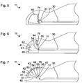
- FIG. 2 shows a schematic representation of an embodiment with a light distribution device 40 at the distal end 11 of the endoscope 10.
- the light distribution device 40 includes a plurality of prisms 41, 42, 43, 44 of one or more different transparent materials.
- the prisms 41, 42, 43, 44 are joined together, for example, by means of a cement, an adhesive or in some other way to the light distribution device 40.
- a respective reflective surface 52, 53, 54 is arranged.
- the reflective surfaces 52, 54 are arranged opposite further reflective surfaces 51, 55.
- the light distribution device 40 has a light entry surface 47, which is coupled via a collimator with the light exit surface 31 of the light guide 30.
- the light entry surface 47 comprises a plurality of partial regions which are each formed by one of the prisms 41, 42, 43, 44.
- the collimator 61 is formed and arranged to collimate light emerging from the light exit surface 31 of the light guide 30 illuminating light.
- the light exit surface 31 of the light guide 30 is arranged in particular at the focus of the collimator 61.
- the reflective surfaces 51, 52, 53, 54, 55 are particularly flat and have their smallest mutual distance near the light entry surface 47.
- Each individual reflective surface 51, 52, 53, 54, 55 may be partially transparent or have a reflectance, for example in the range of 0.2 to 0.4 or in the range of 0.4 to 0.6 or in the range of 0.6 to 0.8.
- the outer reflective surfaces 51, 55 have a high reflectance of 0.9 or more and the reflective surfaces 52, 53, 54 between the prisms 41, 42, 43, 44 each have a mean reflectance in the range of 0.3 to 0, 7 on.
- all reflective surfaces 51, 52, 53, 54, 55 have a high reflectance of 0.9 or more. By using total reflection, a reflectance of 1 can be achieved.
- Column between the prisms 41, 42, 43, 44 are provided, in which a gas or other medium having a refractive index, which is smaller than the refractive indices of the materials of the prisms 41, 42, 43, 44, is arranged.
- Illumination light emanating from the light exit surface 31 of the light guide 30 is collimated by the collimator 61 and enters the light distribution device at the light entry surface 47.
- Reflections on the fan-shaped arranged reflective surfaces 51, 52, 53, 54, 55, the illumination light in a direction parallel to the plane of the FIG. 2 fanned out to illuminate a space area or a solid angle area in the direction parallel to the plane of the FIG. 2 occupies a much larger angle than in the direction perpendicular to the plane of the FIG. 2 ,
- the light distribution device 40 makes possible a distribution of the illumination light into all possible fields of view of the endoscope 10 corresponding to the viewing directions 21 to 24.
- FIG. 3 shows a schematic representation of a further embodiment, which in some features of the above with reference to FIG. 2 illustrated embodiment is similar.
- a light distribution device 40 is provided which comprises a plurality of prisms and a plurality of reflective surfaces.
- FIG. 3 some features, the corresponding features of the embodiment of the FIG. 2 similar, not provided with reference numerals.
- the light entry surface 47 is convexly curved and has a collimating or at least divergence of the illumination light reducing effect.
- a plurality of illumination light beams 64 are shown in dashed lines to indicate the distribution of the illumination light by the light distribution device 40.
- FIG. 4 shows a schematic representation of a further embodiment, the embodiments of the FIGS. 2 and 3 similar in some features.
- a light distribution device 40 is provided which comprises a plurality of prisms and a plurality of reflective surfaces.
- the corresponding features of the embodiment of the FIG. 2 similar, not provided with reference numerals.
- the embodiment of the FIG. 4 differs from the embodiments of the FIGS. 2 and 3 among other things in that a collimator 61 is provided, which is joined to the prisms of the light distribution device 40 or is part of the light distribution device 40. Therefore, the light entrance surface 47 of the light distribution device 40 is simultaneously the light entrance surface of the collimator 61.
- the interface between the collimator 61 and the prisms of the light distribution device 40 may be as shown in FIG FIG. 4 indicated in sections even or deviating from the representation in FIG. 4 be continuously curved or flat overall.
- the light exit surface 48 of the light distribution device 40 differs from the embodiments of the FIGS. 2 and 3 further characterized in that the light exit surface 48 of the light distribution device 40 is not flat in sections, but partially curved convexly.
- the light exit surface 48 comprises a plurality of spherical, elliptical, toric or cylindrical sections each adjacent to a single prism. With the curvature of the light exit surface 48 or the sections of the light exit surface 48 adjoining the individual prisms, the distribution of the illumination light emerging from the light distribution device 40 can be adjusted. Deviating from the illustration in FIG. 4 the light exit surface 48 may be partially concave.
- FIG. 5 shows a schematic representation of a further embodiment, which in some features the embodiments of the FIGS. 2 to 4 is similar, in particular the embodiment of the FIG. 2 ,
- a collimator 61 and a light distribution device 40 are provided, which are the embodiment of the FIG. 2 correspond.
- FIG. 5 some features, the corresponding Features of the embodiment of FIG. 2 similar, not provided with reference numerals. For a corresponding reason, the reflecting surfaces of the light distribution device 40 are not shown.
- the light distribution device 40 is pivotable about a pivot axis 74.
- the pivot axis 74 is perpendicular to the plane of the FIG. 5 and in particular parallel to in FIG. 1 illustrated pivot axis of the viewing direction of the endoscope.
- the contour of the light distribution device 40 is in FIG. 5 shown in two different positions, once in a solid line and once in a broken line.
- the pivot axis 74 By pivoting the light distribution device 40 about the pivot axis 74, the distribution of the illumination light can be changed.
- the pivot axis 74 is arranged close to the light entry surface of the light distribution device 40. Deviating from this, the pivot axis can be arranged at a different location inside or outside the contour of the light distribution device 40.
- FIG. 6 shows a schematic representation of another embodiment, which in some features of the embodiment of the FIG. 2 similar.
- a light distribution device 40 is provided, the above based on the FIG. 2 corresponds to the light distribution device shown.
- FIG. 2 some features, the corresponding features of the embodiment of the FIG. 2 similar, not provided with reference numerals. For a corresponding reason, the reflecting surfaces of the light distribution device 40 are only partially shown.
- the embodiment of the FIG. 6 differs from the embodiment of the FIG. 2 further characterized in that the light distribution device in a direction 76 is movable.
- the direction 76 is in particular perpendicular to the above based on the FIG. 1 shown longitudinal axis of the endoscope and parallel to the plane of the FIG. 6 , Alternatively, the light distribution device 40 can be moved along a curved path.
- the light distribution device 40 is in FIG. 6 shown in two positions, once in a solid line and once in a broken line. In the sense of a clear representation, in each case only two reflective surfaces 51, 52 or 54, 55 are shown in addition to the contour of the light distribution device 40 and provided with reference numerals.
- the distribution of the illumination light can be influenced in particular by the fact that the illumination light is coupled into different prisms and is subsequently reflected by reflecting surfaces which are oriented differently.
- FIG. 7 shows a schematic representation of another embodiment, which in some features above with reference to FIGS. 2 to 4 illustrated embodiments is similar.
- a light distribution device 40 is provided which has a plurality of prisms 41, 42, 43, 44, 45 and a plurality of reflective surfaces 51, 52, 53, 54, 55, 56.
- a collimator 61 is provided, which is joined to the prisms 41, 42, 43, 44, 45 of the light distribution device 40 or is part of the light distribution device 40.
- the light guide 30 has a curvature at the distal end.
- the light exit surface 31 of the light guide 30 is arranged and aligned such that illuminating light emerging from the light exit surface 31 of the light guide 30 falls onto the collimator 61.
- FIGS. 2 to 7 embodiments shown can be combined with each other in other ways, for example, the convex or concave curvature of the light entrance surface, the convex or concave curvature of the light exit surface of the light distribution device, the embodiment and the arrangement of the collimator, the pivotability and the curvature of the light guide near its light exit surface.
- a collimator or a collimating convex light entry surface of the light distribution device can be dispensed with in order to effect a different distribution of the illumination light.
- a lens or a corresponding curvature of the light entry surface of the light distribution device can be provided, which does not substantially reduce or even increase the divergence of the illumination light emerging from the light exit surface of the light guide.
- an internal light source may be provided at the proximal end of the endoscope.
- a light source may be provided at the distal end 11 of the endoscope.
- the light distribution device may comprise non-prismatic transparent bodies instead of prisms.
- the light distribution device may comprise non-prismatic transparent bodies instead of prisms.
- the light distribution device can deviate from the above representations with reference to FIG FIGS. 2 to 7 have no prisms.
- the reflective surfaces are, for example similar to conventional household mirrors arranged on thin glass panels, which can be mirrored on one or both sides.
Landscapes
- Physics & Mathematics (AREA)
- Health & Medical Sciences (AREA)
- Life Sciences & Earth Sciences (AREA)
- Surgery (AREA)
- Optics & Photonics (AREA)
- Biomedical Technology (AREA)
- Animal Behavior & Ethology (AREA)
- Radiology & Medical Imaging (AREA)
- Nuclear Medicine, Radiotherapy & Molecular Imaging (AREA)
- Engineering & Computer Science (AREA)
- Biophysics (AREA)
- Heart & Thoracic Surgery (AREA)
- Medical Informatics (AREA)
- Molecular Biology (AREA)
- Pathology (AREA)
- General Health & Medical Sciences (AREA)
- Public Health (AREA)
- Veterinary Medicine (AREA)
- Astronomy & Astrophysics (AREA)
- General Physics & Mathematics (AREA)
- Endoscopes (AREA)
- Instruments For Viewing The Inside Of Hollow Bodies (AREA)
Description
- Die vorliegende Erfindung bezieht sich auf ein Endoskop mit schwenkbare Blickrichtiung.
- Neben Endoskopen für medizinische und nicht-medizinische technische Anwendungen, deren Blickrichtung parallel zur Längsachse des Schafts des Endoskops ist, wurden bereits früh Endoskope mit anderen feststehenden Blickrichtungen entwickelt. Mit der Blickrichtung eines Endoskops ist hier und im Folgenden immer die Richtung vom distalen Ende des Endoskops aus gemeint, in der ein Gegenstand liegt, der in der Mitte des mittels des Endoskops erfassten Bilds erscheint. Bei vielen Anwendungen ist jedoch eine feste Blickrichtung nachteilig. Im ungünstigsten Fall muss beispielsweise während eines medizinischen Eingriffs mehrfach das Endoskop gewechselt werden. In solchen Fällen ist die Verwendung eines Endoskops mit einer in situ einstellbaren bzw. verstellbaren Blickrichtung vorteilhaft.
- Die Beobachtung eines Gegenstands in einem Hohlraum mittels eines Endoskops setzt in der Regel eine Beleuchtung des Gegenstands voraus. Dazu weist ein Endoskop beispielsweise Lichtwellenleiter, insbesondere Glasfasern, auf, mittels derer Beleuchtungslicht vom proximalen Ende des Endoskops entlang des Schafts zum distalen Ende des Endoskops übertragen wird. Lichtaustrittsflächen der Lichtwellenleiter am distalen Ende des Endoskops sind so angeordnet und ausgebildet, dass das gesamte Sichtfeld bzw. Blickfeld ausreichend ausgeleuchtet wird.
- Um das gesamte Sichtfeld für alle möglichen Blickrichtungen auszuleuchten, sind beispielsweise mehrere Lichtaustrittsflächen vorgesehen, durch die Beleuchtungslicht in unterschiedliche Richtungen austritt. Lichtwellenleiter zu diesen Lichtaustrittsflächen weisen teilweise unmittelbar proximal der Lichtaustrittsfläche Krümmungen mit kleinen Radien auf. Spätestens beim Übergang zu immer kleineren Schaftdurchmessern werden die Krümmungsradien jedoch bald so gering, dass ein Bruch von Lichtwellenleitern nicht mehr die Ausnahme, sondern die Regel wäre. Außerdem gehen bei zu kleinem Krümmungsradius die lichtleitenden Eigenschaften eines Lichtwellenleiters verloren.
- In der
DE 600 15 375 T2 ist eine Anordnung mehrerer Prismen beschrieben. Eines der Prismen ist um eine Achse rotierbar, um Beleuchtungslicht in eine einstellbare Blickrichtung zu werfen. Diese Anordnung ist jedoch allenfalls mit hohem Aufwand weiter miniaturisierbar. Bei Endoskopen mit immer dünneren Schäften sind alternative, weiter miniaturisierbare Konzepte erforderlich. - Dokument
US 3,896,793 offenbart ein Endoskop mit einstellbarer Blickrichtung mit einem Beleuchtungslichtfaserbündel. - Eine Aufgabe der vorliegenden Erfindung besteht darin, ein verbessertes Endoskop mit schwenkbarer Blickrichtung zu schaffen.
- Diese Aufgabe wird durch den Gegenstand des unabhängigen Anspruchs 1 gelöst.
- Weiterbildungen sind in den abhängigen Ansprüchen angegeben.
- Die vorliegende Erfindung beruht auf der Idee, bei einem Endoskop mit einstellbarer Blickrichtung eine Mehrzahl von zumindest teilweise nebeneinander im Beleuchtungsstrahlengang angeordneten reflektierenden Flächen vorzusehen, um alle möglichen Sichtfelder des Endoskops auszuleuchten. Durch die Mehrzahl reflektierender Flächen kann das Beleuchtungslicht aufgefächert werden, um zumindest in einer Richtung einen großen Winkelbereich zu beleuchten.
- Ein Endoskop mit relativ zum Endoskop schwenkbarer Blickrichtung umfasst einen Beleuchtungsstrahlengang zum Übertragen von Beleuchtungslicht und eine Mehrzahl von reflektierenden Flächen zum Reflektieren von Beleuchtungslicht, wobei die reflektierenden Flächen bezogen auf die vorgesehene Lichtausbreitungsrichtung von Beleuchtungslicht im Beleuchtungsstrahlengang zumindest teilweise nebeneinander im Beleuchtungsstrahlengang angeordnet sind.
- Die Blickrichtung des Endoskops ist insbesondere um eine Schwenkachse schwenkbar, die senkrecht zur Längsachse des Endoskops oder zumindest nicht parallel zur Längsachse des Endoskops ist. Das Endoskop kann eine oder mehrere Leuchtdioden oder eine oder mehrere andere Lichtquellen am distalen Ende oder am proximalen Ende aufweisen. In diesem Fall erstreckt sich der Beleuchtungsstrahlengang von der bzw. den Lichtquellen bis zu einem oder mehreren Beleuchtungsfenstern am distalen Ende des Endoskops. Alternativ erstreckt sich der Beleuchtungsstrahlengang von einer Kupplung am proximalen Ende des Endoskops bis zu einem oder mehreren Beleuchtungsfenstern am distalen Ende des Endoskops, wobei die Kupplung ausgebildet ist, um das Endoskop mittels eines Lichtleitkabels mit einer Lichtquelle zu koppeln. Zur Übertragung von Beleuchtungslicht vom proximalen Ende zum distalen Ende des Endoskops weist dieses beispielsweise einen Lichtwellenleiter, ein Bündel von Lichtwellenleitern oder einen anderen Lichtleiter auf.
- Der Querschnitt des Beleuchtungsstrahlengangs ist insbesondere unmittelbar lichtstromaufwärts der reflektierenden Flächen einfach zusammenhängend. Das Endoskop kann mehrere Beleuchtungsstrahlengänge aufweisen, wobei innerhalb jedes einzelnen Beleuchtungsstrahlengangs eine Mehrzahl reflektierender Flächen bezogen auf die vorgesehene Lichtausbreitungsrichtung zumindest teilweise nebeneinander angeordnet ist. Insbesondere weist das Endoskop zwei oder mehr Beleuchtungsstrahlengänge an gegenüberliegenden Seiten eines Beobachtungsstrahlengangs auf, wobei am distalen Ende des Endoskops Lichtaustrittsflächen eines ersten Beleuchtungsstrahlengangs und Lichtaustrittsflächen eines zweiten Beleuchtungsstrahlengangs an gegenüberliegenden Seiten einer Lichteintrittsfläche des Beobachtungsstrahlengangs angeordnet sind.
- Die vorgesehene Lichtausbreitungsrichtung von Beleuchtungslicht ist von der Lichtquelle oder vom proximalen Ende des Endoskops zu der oder den Lichtaustrittsflächen am distalen Ende des Endoskops. Die reflektierenden Flächen erstrecken sich insbesondere zumindest teilweise im Wesentlichen parallel zur vorgesehenen Lichtausbreitungsrichtung. Da Beleuchtungslicht real von einer ausgedehnten, nicht punktförmigen Lichtquelle ausgeht, breitet es sich in einem Beleuchtungsstrahlengang mit endlichem Querschnitt nie vollkommen parallel aus. Als Lichtausbreitungsrichtung wird deshalb beispielsweise die mittlere Lichtausbreitungsrichtung innerhalb des Querschnitts des Beleuchtungsstrahlengangs angesehen.
- Insbesondere unterteilen die reflektierenden Flächen den Querschnitt des Beleuchtungsstrahlengangs in mehrere Teilquerschnitte. Durch eine auffächernde Wirkung der reflektierenden Flächen auf das Beleuchtungslicht kann die Lichtausbreitungsrichtung (wiederum im Sinne einer mittleren Lichtausbreitungsrichtung innerhalb des betreffenden Teilquerschnitts) zwischen jedem Paar benachbarter reflektierender Flächen anders sein.
- Das Kriterium der Anordnung einer ersten reflektierenden Fläche und einer zweiten reflektierenden Fläche zumindest teilweise nebeneinander ist insbesondere auf die Lichtausbreitungsrichtungen unmittelbar lichtstromaufwärts und unmittelbar lichtstromabwärts der lichtstromaufwärts angeordneten Ränder der reflektierenden Flächen bezogen. Dabei ist die Lichtausbreitungsrichtung unmittelbar lichtstromabwärts des lichtstromaufwärtigen Rands einer reflektierenden Fläche nur unwesentlich verändert, weil nur ein geringer Teil des Beleuchtungslichts bereits an der reflektierenden Fläche reflektiert ist.
- Eine erste reflektierende Fläche und eine zweite reflektierende Fläche sind bezogen auf die vorgesehene Lichtausbreitungsrichtung von Beleuchtungslicht im Beleuchtungsstrahlengang zumindest teilweise nebeneinander im Beleuchtungsstrahlengang angeordnet, wenn sie in Bezug auf die Lichtausbreitungsrichtung unmittelbar lichtstromaufwärts und bezogen auf die Lichtausbreitungsrichtung unmittelbar lichtstromabwärts des lichtstromaufwärtigen Rands der ersten reflektierenden Fläche und bezogen auf die Lichtausbreitungsrichtung unmittelbar lichtstromaufwärts und bezogen auf die Lichtausbreitungsrichtung unmittelbar lichtstromabwärts des lichtstromaufwärtigen Rands der zweiten reflektierenden Fläche nebeneinander angeordnet sind. Bezogen auf eine Richtung liegen zwei reflektierende Flächen nebeneinander, wenn eine zu der Richtung senkrechte Ebene beide reflektierende Flächen schneidet. Insbesondere werden zu den Lichtausbreitungsrichtungen senkrechte Ebenen betrachtet, die die reflektierenden Flächen an deren lichtstromaufwärtigen Rändern oder nahe deren lichtstromaufwärtigen Rändern schneiden.
- Bereits einem intuitiven Verständnis entsprechend sind die reflektierenden Flächen der in der oben erwähnten
DE 600 15 375 T2 beschriebenen Prismen nicht zumindest teilweise nebeneinander im Sinne der vorliegenden Erfindung angeordnet. Beleuchtungslicht kann nicht gleichzeitig auf beide reflektierenden Flächen der Prismen fallen. Vielmehr wird Beleuchtungslicht zunächst von der reflektierenden Fläche eines ersten Prismas um 90 Grad abgelenkt und dann von der reflektierenden Fläche eines zweiten Prismas wiederum um 90 Grad abgelenkt. Die Anordnung ist dazu ausgebildet, dass Beleuchtungslicht, das auf die zweite reflektierende Fläche trifft, zuvor von der ersten reflektierenden Fläche um 90 Grad abgelenkt wurde. Die reflektierenden Flächen sind also bezogen auf die Lichtausbreitungsrichtung nicht nebeneinander, sondern hintereinander angeordnet. - Auch bezogen auf die oben angegebenen Kriterien für eine Anordnung reflektierender Flächen zumindest teilweise nebeneinander sind die reflektierenden Flächen der Prismen gemäß
DE 600 15 375 T2 nicht nebeneinander angeordnet. Es gibt zwar Ebenen, die von den reflektierenden Flächen beider Prismen geschnitten werden, jedoch gibt es beispielsweise keine Ebene senkrecht zur Lichtausbreitungsrichtung zwischen den beiden reflektierenden Flächen, die beide reflektierenden Flächen schneidet. - Die Mehrzahl reflektierender Flächen ermöglicht zumindest innerhalb einer Richtung eine Aufweitung bzw. Auffächerung des Beleuchtungslichts und damit eine Ausleuchtung aller möglicher Sichtfelder eines Endoskops mit schwenkbarer Blickrichtung. Die Anordnung einer Mehrzahl reflektierender Flächen kann mit geringem oder verhältnismäßigem Aufwand miniaturisierbar sein. Da die reflektierenden Flächen starr bzw. unbewegt angeordnet sein können, kann auch eine große mechanische Robustheit und eine Unempfindlichkeit gegenüber Sterilisationsprozessen im Autoklaven realisierbar sein.
- Bei einem Endoskop, wie es hier beschrieben ist, können die reflektierenden Flächen fächerförmig angeordnet sein.
- Die reflektierenden Flächen sind insbesondere fächerförmig angeordnet, wenn ihre Abstände in eine Richtung zunehmen. Insbesondere nehmen ihre Abstände in der Lichtausbreitungsrichtung zu.
- Soweit die reflektierenden Flächen eben sind, sind sie insbesondere dann fächerförmig angeordnet, wenn alle Ebenen, in denen die reflektierenden Flächen liegen sich in einer einzigen Gerade oder in mehreren parallelen Geraden schneiden, wobei der maximale Abstand zweier paralleler Schnittgeraden nicht größer ist als die linearen Abmessungen der reflektierenden Flächen in einer Richtung senkrecht zu den Schnittgeraden oder nicht größer als die Hälfte, ein Drittel oder ein Fünftel dieser Abmessung.
- Die fächerförmige Anordnung der reflektierenden Flächen ermöglicht eine Aufweitung bzw. Auffächerung des Beleuchtungslichts in einer Richtung. Durch die Anzahl, Größe und Gestalt der reflektierenden Flächen und ihre Winkelabstände ist die Verteilung des Beleuchtungslichts einstellbar.
- Bei einem Endoskop, wie es hier beschrieben ist, können die Flächennormalen ebener reflektierender Flächen der Mehrzahl von reflektierenden Flächen in einer Ebene senkrecht zu einer Schwenkachse der Blickrichtung liegen.
- Insbesondere sind alle reflektierenden Flächen der Mehrzahl reflektierender Flächen eben und die Flächennormalen aller reflektierender Flächen liegen in einer Ebene senkrecht zur Schwenkachse der Blickrichtung. Alternativ ist nur eine Teilmenge der reflektierenden Flächen eben, wobei die Flächennormalen aller ebener reflektierender Flächen oder zumindest die Flächennormalen mehrerer ebener reflektierender Flächen in einer Ebene senkrecht zu einer Schwenkachse der Blickrichtung liegen.
- Bei einem Endoskop, wie es hier beschrieben ist, können lokale Flächennormalen reflektierender Flächen in mittleren Bereichen der reflektierenden Flächen in einer Ebene senkrecht zu einer Schwenkachse der Blickrichtung liegen.
- Die Ausbildung und Anordnung ebener oder gekrümmter reflektierender Flächen derart, dass die Flächennormalen bzw. im Fall gekrümmter reflektierender Flächen die lokalen Flächennormalen in mittleren Bereichen der reflektierenden Flächen in einer Ebene senkrecht zur Schwenkachse der Blickrichtung liegen, kann eine präzise Auffächerung des Beleuchtungslichts in der Schwenkrichtung ermöglichen. Durch die Anzahl, Größe, Gestalt und insbesondere auch Krümmung der reflektierenden Flächen kann die Verteilung des Beleuchtungslichts eingestellt werden.
- Bei einem Endoskop, wie es hier beschrieben ist, kann eine reflektierende Fläche der Mehrzahl von reflektierenden Flächen einen Reflexionsgrad von höchstens 0,75 aufweisen.
- Insbesondere weist die reflektierende Fläche oder weisen mehrere oder alle reflektierenden Flächen der Mehrzahl von reflektierenden Flächen einen Reflexionsgrad von höchstens 0,75 oder höchstens 0,50 oder höchstens 0,25 auf. Ein Reflexionsgrad der reflektierenden Flächen, der deutlich kleiner als 1 ist, kann eine weiter verfeinerte Auffächerung des Beleuchtungslichts und eine besonders hohe Gleichmäßigkeit der Intensität des Beleuchtungslichts ermöglichen. Dazu kann insbesondere beitragen, dass Beleuchtungslicht nicht nur zwischen zwei nächst benachbarten reflektierenden Flächen hin- und herreflektiert wird, sondern teilweise nacheinander an mehreren verschiedenen reflektierenden Flächen reflektiert wird.
- Ein Endoskop, wie es hier beschrieben ist, kann eine Lichtverteilungseinrichtung aufweisen, die eine Mehrzahl transparenter Körper umfasst, wobei die reflektierenden Flächen an Grenzflächen zwischen jeweils zwei aneinanderangrenzenden transparenten Körpern vorliegen.
- Die transparenten Körper können Prismen aus einem transparenten Material sein.
- Mit einem Prisma ist insbesondere ein Prisma im strengen Sinne der Geometrie gemeint, also ein Körper mit zwei gegenüberliegenden, parallelen und gleichen Begrenzungsflächen, dessen übrige Begrenzungsflächen Parallelogramme sind. In der Optik wird der Begriff des Prismas oft im weiteren Sinne verwendet, um transparente Körper zu bezeichnen, deren Oberfläche zumindest zwei nicht-parallele ebene Abschnitte aufweisen, durch die Licht in einer ersten Richtung eintritt und in einer zweiten Richtung austritt. In weiterer Verallgemeinerung kann die Lichtverteilungseinrichtung des hier beschriebenen Endoskops eine Mehrzahl nicht-prismatischer transparenter Körper aufweisen.
- Die Ausbildung der reflektierenden Flächen an Grenzflächen zwischen miteinander beispielsweise verkitteten transparenten Körpern kann besonders robust und gleichzeitig weitgehend miniaturisierbar sein. Die reflektierenden Flächen sind durch die transparenten Körper geschützt, die Lichtverteilungseinrichtung bildet ein kompaktes und mechanisch robustes Bauteil, das leicht montierbar ist.
- Bei einem Endoskop mit einer Lichtverteilungseinrichtung, wie es hier beschrieben ist, können an einzelne transparente Körper der Lichtverteilungseinrichtung angrenzende Abschnitte einer Lichtaustrittsfläche der Lichtverteilungseinrichtung eben sein.
- Alternativ können bei einem Endoskop mit einer Lichtverteilungseinrichtung, wie es hier beschrieben ist, an einzelne transparente Körper der Lichtverteilungseinrichtung angrenzende Abschnitte einer Lichtaustrittsfläche der Lichtverteilungseinrichtung gekrümmt sein.
- In einem einfachen Fall weist jeder transparente Körper eine ebene oder beispielsweise zylindrisch oder elliptisch oder sphärisch oder torisch gekrümmte Fläche auf, die an gegenüberliegenden Rändern an zwei verschiedene reflektierende Flächen der Mehrzahl von reflektierenden Flächen angrenzt, und die einen Abschnitt der Lichtaustrittsfläche der Lichtverteilungseinrichtung bildet. Durch die ebene oder gekrümmte Ausgestaltung dieser Abschnitte der Lichtaustrittsfläche kann die Verteilung des Beleuchtungslichts bzw. seiner Intensität weiter verbessert werden.
- Bei einem Endoskop mit einer Lichtverteilungseinrichtung, wie es hier beschrieben ist, können an einzelne transparente Körper der Lichtverteilungseinrichtung angrenzende Abschnitte einer Lichteintrittsfläche der Lichtverteilungseinrichtung eben sein.
- Alternativ sind an einzelne transparente Körper der Lichtverteilungseinrichtung angrenzende Abschnitte einer Lichteintrittsfläche der Lichtverteilungseinrichtung gekrümmt.
- In einem einfachen Fall weist ein transparenter Körper einen ebenen, zylindrisch, torisch, elliptisch, sphärisch oder anders gekrümmten Oberflächenabschnitt auf, der an gegenüberliegenden Rändern an zwei reflektierende Flächen angrenzt und einen Teil der Lichteintrittsfläche der Lichtverteilungseinrichtung bildet. Durch die Ausgestaltung der Lichteintrittsfläche kann die Verteilung des Beleuchtungslichts verbessert werden. Insbesondere kann eine konvex gekrümmte Lichteintrittsfläche der Lichtverteilungseinrichtung kollimierend wirken. Alternativ kann durch eine entsprechend gekrümmte oder abschnittsweise oder insgesamt eben ausgebildete Lichteintrittsfläche der Lichtverteilungseinrichtung eine Divergenz oder Konvergenz des Beleuchtungslichts eingestellt werden. Die Lichteintrittsfläche kann ferner mit einer Leuchtdiode oder einer anderen Lichtquelle oder einer Lichtaustrittsfläche eines Lichtleiters verschweißt, verklebt oder auf andere Weise gefügt sein. Dies ermöglicht eine dauerhafte und dauerhaft präzise Ausrichtung der Lichtquelle bzw. der Lichtaustrittsfläche des Lichtleiters relativ zur Lichtverteilungseinrichtung.
- Bei einem Endoskop, wie es hier beschrieben ist, können die reflektierenden Flächen zumindest entweder um eine Achse schwenkbar oder entlang eines Wegs verschiebbar sein.
- Selbst eine geringfügige Verschwenkung oder Verschiebung kann bei entsprechender Ausgestaltung der reflektierenden Flächen eine Veränderung des mittels der reflektierenden Flächen ausgeleuchteten Raumwinkelbereichs ermöglichen. Insbesondere wenn das Endoskop eine Lichtverteilungseinrichtung aufweist, wie sie oben beschrieben ist, kann diese gleichzeitig robust und auf einfache und präzise Weise schwenkbar oder verschiebbar ausgebildet sein.
- Bei einem Endoskop, bei dem die reflektierenden Flächen zumindest entweder um eine Achse schwenkbar oder entlang eines Wegs verschiebbar sind, ist insbesondere die Beleuchtung der reflektierenden Flächen von der durch Schwenken oder Schieben der reflektierenden Flächen eingestellten Position der reflektierenden Flächen abhängig.
- Insbesondere kann eingestellt werden, auf welche reflektierende Fläche Beleuchtungslicht fällt oder in welchem Winkel Beleuchtungslicht auf eine oder in welchen Winkeln Beleuchtungslicht auf mehrere reflektierende Flächen fällt. Dadurch kann der mit Beleuchtungslicht ausgeleuchtete Raumwinkelbereich eingestellt werden.
- Nachfolgend werden Ausführungsformen anhand der beigefügten Figuren näher erläutert. Es zeigen:
- Figur 1
- eine schematische Darstellung eines Endoskops mit einstellbarer Blickrichtung;
- Figur 2
- eine schematische Darstellung einer Ausführungsform eines distalen Endes eines Endoskops;
- Figur 3
- eine schematische Darstellung einer weiteren Ausführungsform eines distalen Endes eines Endoskops;
- Figur 4
- eine schematische Darstellung einer weiteren Ausführungsform eines distalen Endes eines Endoskops;
- Figur 5
- eine schematische Darstellung einer weiteren Ausführungsform eines distalen Endes eines Endoskops;
- Figur 6
- eine schematische Darstellung einer weiteren Ausführungsform eines distalen Endes eines Endoskops;
- Figur 7
- eine schematische Darstellung einer weiteren Ausführungsform eines distalen Endes eines Endoskops.
-
Figur 1 zeigt eine schematische Darstellung eines Endoskops 10 mit einem distalen Ende 11, einem proximalen Ende 12 und einem starren Schaft 14, der sich vom distalen Ende 11 bis zum proximalen Ende 12 erstreckt. Alternativ ist der Schaft 14 flexibel oder teilweise flexibel. Der Querschnitt des Schafts 14 oder zumindest die äußere Kontur des Querschnitts des Schafts 14 ist zwischen dem distalen Ende 11 und dem proximalen Ende 12 konstant oder im Wesentlichen konstant. Insbesondere ist die Kontur des Querschnitts des Schafts 14 kreisförmig oder elliptisch. In diesem Fall ist die inFigur 1 dargestellt Längsachse 18 des Endoskops 10 die Symmetrieachse der Mantelfläche des Schafts 14 zwischen dem distalen Ende 12 und dem proximalen Ende 11. Bei einer zylindrischen Mantelfläche des Schafts 14 ist die Längsachse 18 auch die Menge der Mittelpunkte oder Flächenschwerpunkte der Querschnitte des Schafts 14 zwischen dem distalen Ende 12 und dem proximalen Ende 11. Bei einer kreiszylindrischen Mantelfläche des Schafts 14 ist die Längsachse 18 auch die Symmetrieachse der Mantelfläche. - Am distalen Ende 12 weicht die Gestalt des Schafts 14 von der Zylindersymmetrie ab, wie dies beispielhaft in
Figur 1 dargestellt ist. Insbesondere weist der Schaft 14 am distalen Ende 12 eine Öffnung auf, die durch ein transparentes Fensterbauteil mit einer gewölbten Oberfläche 20 verschlossen ist. Insbesondere verschließt das Fensterbauteil 20 die Öffnung hermetisch dicht. Die Oberfläche 20 des Fensterbauteils hat beispielsweise die Gestalt eines Ausschnitts eines Kreiszylindermantels, wobei die Symmetrieachse des Kreiszylinders senkrecht zur Längsachse 18 des Endoskops 10 und zur Zeichenebene derFigur 1 ist. Alternativ hat die Oberfläche 20 des transparenten Fensterbauteils die Gestalt eines Ausschnitts einer Kugeloberfläche oder eines rotationssymmetrischen oder nicht rotationssymmetrischen Ellipsoids. - Am distalen Enden 12 des Endoskops 10 sind im Schaft 14 optische Einrichtungen angeordnet, die in
Figur 1 nicht dargestellt sind. Diese optischen Einrichtungen ermöglichen eine Variation der Blickrichtung des Endoskops zwischen einer ersten extremen Blickrichtung 21 und einer zweiten extremen Blickrichtung 22. Die Blickrichtung ist zwischen den beiden extremen Blickrichtungen 21, 22 um eine Schwenkachse 28 schwenkbar, die senkrecht zur Zeichenebene derFigur 1 ist. Die Blickrichtung ist jeweils die Richtung bezogen auf das distale Ende 12 des Endoskops 10, in der ein Gegenstand liegt, der in der Mitte eines mittels des Endoskops 10 erfassten Bilds erscheint. - Bei dem in
Figur 1 dargestellten Beispiel ist die erste extreme Blickrichtung 21 parallel oder im Wesentlichen parallel zur Längsachse 18 des Endoskops 10. Zwischen den extremen Blickrichtungen 21, 22 liegt ein Winkelbereich 29, der bei dem dargestellten Beispiel ca. 120 Grad umfasst. Innerhalb dieses Winkelbereichs ist die Blickrichtung des Endoskops 10 insbesondere kontinuierlich verstellbar. - Am proximalen Ende 11 weist das Endoskop 10 eine erste Kupplung 15 zum optischen Koppeln des Endoskops 10 mit einer Kamera oder ein Okular sowie eine zweite Kupplung 16 zum Koppeln des Endoskops 10 mit einer Lichtquelle über ein Lichtleitkabel auf. Von der zweiten Kupplung 16 führen ein oder mehrere Lichtleiter 30 durch den Schaft 14 bis zum distalen Ende 11 des Endoskops 10. Von einer Lichtquelle erzeugtes Beleuchtungslicht kann über ein Lichtleitkabel, die zweite Kupplung 16 und den oder die Lichtleiter 30 zum distalen Ende 11 des Endoskops 10 übertragen werden.
- Die
Figuren 2 bis 7 zeigen schematische Darstellungen mehrerer alternativer Ausführungsformen des distalen Endes 11 des oben anhand derFigur 1 dargestellten Endoskops 10. DieFiguren 2 bis 7 zeigen jeweils in stark vereinfachter Darstellung einen Schnitt entlang einer Ebene parallel zur Zeichenebene derFigur 1 . Der Schaft bzw. das Gehäuse des Endoskops 10 ist lediglich durch einen Umriss angedeutet. Wellen, Gelenke und andere mechanische Einrichtungen zum Halten, Führen und/oder Bewegen der dargestellten optischen Einrichtungen sind zugunsten der Übersichtlichkeit nicht dargestellt. - Wie bereits erwähnt, umfasst jede der nachfolgend anhand der
Figuren 2 bis 7 dargestellten Ausführungsformen einen Lichtleiter 30, der sich von der zweiten Kupplung 16 am proximalen Ende 12 bis zum distalen Ende 11 des Endoskops 10 erstreckt. Der Lichtleiter 30 umfasst beispielsweise einen Lichtwellenleiter oder ein Bündel von Lichtwellenleitern. Der Lichtleiter 30 ist zum Übertragen von Beleuchtungslicht zum distalen Ende 11 des Endoskops 10 vorgesehen und ausgebildet. Am distalen Ende 11 des Endoskops 10 weist der Lichtleiter 30 eine Lichtaustrittsfläche 31 zum Auskoppeln von Beleuchtungslichts auf. Am distalen Ende 11 des Endoskops 10 wird das Beleuchtungslicht mittels der nachfolgend anhand derFiguren 2 bis 7 dargestellten Einrichtungen in einen vorbestimmten Raumwinkelbereich verteilt. -
Figur 2 zeigt eine schematische Darstellung einer Ausführungsform mit einer Lichtverteilungseinrichtung 40 am distalen Ende 11 des Endoskops 10. Die Lichtverteilungseinrichtung 40 umfasst eine Mehrzahl von Prismen 41, 42, 43, 44 aus einem oder mehreren verschiedenen transparenten Materialien. Die Prismen 41, 42, 43, 44 sind beispielsweise mittels eines Kitts, eines Klebstoffs oder auf andere Weise zu der Lichtverteilungseinrichtung 40 zusammengefügt. Zwischen jeweils zwei benachbarten Prismen 41, 42, 43, 44 ist jeweils eine reflektierende Fläche 52, 53, 54 angeordnet. An den äußersten Prismen 41, 44 sind den reflektierenden Flächen 52, 54 gegenüber weitere reflektierende Flächen 51, 55 angeordnet. Die Lichtverteilungseinrichtung 40 weist eine Lichteintrittsfläche 47 auf, die über einen Kollimator mit der Lichtaustrittsfläche 31 des Lichtleiters 30 gekoppelt ist. Die Lichteintrittsfläche 47 umfasst mehrere Teilbereiche, die jeweils durch eines der Prismen 41, 42, 43, 44 gebildet werden. - Der Kollimator 61 ist ausgebildet und angeordnet, um aus der Lichtaustrittsfläche 31 des Lichtleiters 30 austretendes Beleuchtungslicht zu kollimieren. Dazu ist die Lichtaustrittsfläche 31 des Lichtleiters 30 insbesondere am Fokus des Kollimators 61 angeordnet.
- Die reflektierenden Flächen 51, 52, 53, 54, 55 sind insbesondere eben und weisen ihren kleinsten gegenseitigen Abstand nahe der Lichteintrittsfläche 47 auf. Jede einzelne reflektierende Fläche 51, 52, 53, 54, 55 kann teilweise transparent sein bzw. einen Reflexionsgrad aufweisen, der beispielsweise im Bereich von 0,2 bis 0,4 oder im Bereich von 0,4 bis 0,6 oder im Bereich von 0,6 bis 0,8 liegt. Insbesondere weisen die äußeren reflektierenden Flächen 51, 55 einen hohen Reflexionsgrad von 0,9 oder mehr und die reflektierenden Flächen 52, 53, 54 zwischen den Prismen 41, 42, 43, 44 jeweils einen mittleren Reflexionsgrad im Bereich von 0,3 bis 0,7 auf.
- Alternativ weisen beispielsweise alle reflektierenden Flächen 51, 52, 53, 54, 55 einen hohen Reflexionsgrad von 0,9 oder mehr auf. Durch Nutzung von Totalreflexion ist ein Reflexionsgrad von 1 erreichbar. Dazu können abweichend von der Darstellung in
Figur 2 Spalte zwischen den Prismen 41, 42, 43, 44 vorgesehen sein, in denen ein Gas oder ein anderes Medium mit einem Brechungsindex, der kleiner ist als die Brechungsindizes der Materialien der Prismen 41, 42, 43, 44, angeordnet ist. - Von der Lichtaustrittsfläche 31 des Lichtleiters 30 ausgehendes Beleuchtungslicht wird vom Kollimator 61 kollimiert und tritt an der Lichteintrittsfläche 47 in die Lichtverteilungseinrichtung ein. Durch Reflexionen an den fächerförmig angeordneten reflektierenden Flächen 51, 52, 53, 54, 55 wird das Beleuchtungslicht in einer Richtung parallel zur Zeichenebene der
Figur 2 aufgefächert, um einen Raumbereich bzw. einen Raumwinkelbereich auszuleuchten, der in Richtung parallel zur Zeichenebene derFigur 2 einen wesentlich größeren Winkel einnimmt als in der Richtung senkrecht zur Zeichenebene derFigur 2 . Damit ermöglicht die Lichtverteilungseinrichtung 40 eine Verteilung des Beleuchtungslichts in alle möglichen, den Blickrichtungen 21 bis 24 entsprechende Sichtfelder des Endoskops 10. -
Figur 3 zeigt eine schematische Darstellung einer weiteren Ausführungsform, die in einigen Merkmalen der oben anhand derFigur 2 dargestellten Ausführungsform ähnelt. Insbesondere ist eine Lichtverteilungseinrichtung 40 vorgesehen, die mehrere Prismen und mehrere reflektierende Flächen umfasst. Im Sinne einer übersichtlichen Darstellung sind inFigur 3 einige Merkmale, die entsprechenden Merkmalen der Ausführungsform derFigur 2 ähneln, nicht mit Bezugszeichen versehen. - Im Gegensatz zu der Ausführungsform der
Figur 2 ist kein Kollimator vorgesehen. Stattdessen ist die Lichteintrittsfläche 47 konvex gekrümmt und weist eine kollimierende oder zumindest die Divergenz des Beleuchtungslichts reduzierende Wirkung auf. InFigur 3 sind ferner mehrere Beleuchtungslichtstrahlen 64 in gestrichelten Linien gezeigt, um die Verteilung des Beleuchtungslichts durch die Lichtverteilungseinrichtung 40 anzudeuten. -
Figur 4 zeigt eine schematische Darstellung einer weiteren Ausführungsform, die den Ausführungsformen derFiguren 2 und 3 in einigen Merkmalen ähnelt. Insbesondere ist eine Lichtverteilungseinrichtung 40 vorgesehen, die mehrere Prismen und mehrere reflektierende Flächen umfasst. Im Sinne einer übersichtlichen Darstellung sind inFigur 4 einige Merkmale, die entsprechenden Merkmalen der Ausführungsform derFigur 2 ähneln, nicht mit Bezugszeichen versehen. - Die Ausführungsform der
Figur 4 unterscheidet sich von den Ausführungsformen derFiguren 2 und 3 unter anderem dadurch, dass ein Kollimator 61 vorgesehen ist, der mit den Prismen der Lichtverteilungseinrichtung 40 gefügt ist bzw. Bestandteil der Lichtverteilungseinrichtung 40 ist. Deshalb ist die Lichteintrittsfläche 47 der Lichtverteilungseinrichtung 40 gleichzeitig die Lichteintrittsfläche des Kollimators 61. Die Grenzfläche zwischen dem Kollimator 61 und den Prismen der Lichtverteilungseinrichtung 40 kann wie inFigur 4 angedeutet abschnittsweise eben oder abweichend von der Darstellung inFigur 4 kontinuierlich gekrümmt oder insgesamt eben sein. - Die in
Figur 4 dargestellte Lichtverteilungseinrichtung 40 unterscheidet sich von den Ausführungsformen derFiguren 2 und 3 ferner dadurch, dass die Lichtaustrittsfläche 48 der Lichtverteilungseinrichtung 40 nicht abschnittsweise eben, sondern abschnittsweise konvex gekrümmt ist. Insbesondere umfasst die Lichtaustrittsfläche 48 mehrere jeweils an ein einziges Prisma angrenzende sphärische, elliptische, torische oder zylindrische Abschnitte. Mit der Krümmung der Lichtaustrittsfläche 48 bzw. der an die einzelnen Prismen angrenzenden Abschnitte der Lichtaustrittsfläche 48 kann die Verteilung des aus der Lichtverteilungseinrichtung 40 austretenden Beleuchtungslichts eingestellt werden. Abweichend von der Darstellung inFigur 4 kann die Lichtaustrittsfläche 48 abschnittsweise konkav sein. -
Figur 5 zeigt eine schematische Darstellung einer weiteren Ausführungsform, die in einigen Merkmalen den Ausführungsformen derFigur 2 bis 4 ähnelt, insbesondere der Ausführungsform derFigur 2 . Insbesondere sind ein Kollimator 61 und eine Lichtverteilungseinrichtung 40 vorgesehen, die der Ausführungsform derFigur 2 entsprechen. Im Sinne einer übersichtlichen Darstellung sind inFigur 5 einige Merkmale, die entsprechenden Merkmalen der Ausführungsform derFigur 2 ähneln, nicht mit Bezugszeichen versehen. Aus entsprechendem Grund sind die reflektierenden Flächen der Lichtverteilungseinrichtung 40 nicht dargestellt. - Abweichend von der Ausführungsform der
Figur 2 ist die Lichtverteilungseinrichtung 40 um eine Schwenkachse 74 schwenkbar. Die Schwenkachse 74 ist senkrecht zur Zeichenebene derFigur 5 und insbesondere parallel zur inFigur 1 dargestellten Schwenkachse der Blickrichtung des Endoskops. Die Kontur der Lichtverteilungseinrichtung 40 ist inFigur 5 in zwei verschiedenen Positionen dargestellt, einmal in durchgezogener Linie und einmal in unterbrochener Linie. - Durch Schwenken der Lichtverteilungseinrichtung 40 um die Schwenkachse 74 kann die Verteilung des Beleuchtungslichts verändert werden. Bei der Ausführungsform der
Figur 5 ist die Schwenkachse 74 nahe an der Lichteintrittsfläche der Lichtverteilungseinrichtung 40 angeordnet. Abweichend davon kann die Schwenkachse an einem anderen Ort innerhalb oder außerhalb der Kontur der Lichtverteilungseinrichtung 40 angeordnet sein. -
Figur 6 zeigt eine schematische Darstellung einer weiteren Ausführungsform, die in einigen Merkmalen der Ausführungsform derFigur 2 ähnelt. Insbesondere ist eine Lichtverteilungseinrichtung 40 vorgesehen, die der oben anhand derFigur 2 dargestellten Lichtverteilungseinrichtung entspricht. Im Sinne einer übersichtlichen Darstellung sind inFigur 2 einige Merkmale, die entsprechenden Merkmalen der Ausführungsform derFigur 2 ähneln, nicht mit Bezugszeichen versehen. Aus entsprechendem Grund sind die reflektierenden Flächen der Lichtverteilungseinrichtung 40 nur teilweise dargestellt. - Im Gegensatz zu der Ausführungsform der
Figur 2 ist kein Kollimator vorgesehen. Die Ausführungsform derFigur 6 unterscheidet sich von der Ausführungsform derFigur 2 ferner dadurch, dass die Lichtverteilungseinrichtung in einer Richtung 76 verfahrbar ist. Die Richtung 76 ist insbesondere senkrecht zur oben anhand derFigur 1 dargestellten Längsachse des Endoskops und parallel zur Zeichenebene derFigur 6 . Alternativ kann die Lichtverteilungseinrichtung 40 entlang eines gekrümmten Wegs verfahrbar sein. - Die Lichtverteilungseinrichtung 40 ist in
Figur 6 in zwei Positionen dargestellt, einmal in durchgezogener Linie und einmal in unterbrochener Linie. Im Sinne einer übersichtlichen Darstellung sind neben der Kontur der Lichtverteilungseinrichtung 40 jeweils nur zwei reflektierende Flächen 51, 52 bzw. 54, 55 dargestellt und mit Bezugszeichen versehen. - Aufgrund des geringen Abstands zwischen der Lichtaustrittsfläche 31 des Lichtleiters 30 und der Lichteintrittsfläche der Lichtverteilungseinrichtung 40 und der im Verhältnis zur Lichteintrittsfläche der Lichtverteilungseinrichtung 40 kleinen Lichtaustrittsfläche 31 des Lichtleiters 30 wird aus der Lichtaustrittsfläche 31 des Lichtleiters 30 austretendes Beleuchtungslicht bei den beiden dargestellten Positionen der Lichtverteilungseinrichtung 40 jeweils überwiegend nur in ein Prisma der Lichtverteilungseinrichtung 40 eingekoppelt. Bei der in unterbrochener Linie dargestellten Position der Lichtverteilungseinrichtung 40 wird Beleuchtungslicht überwiegend in das Prisma 41 zwischen den reflektierenden Flächen 51, 52 eingekoppelt, bei der in durchgezogener Linie dargestellten Position der Lichtverteilungseinrichtung 40 wird Beleuchtungslicht überwiegend in das Prisma 44 zwischen den reflektierenden Flächen 54, 55 eingekoppelt.
- Durch Verschieben der Lichtverteilungseinrichtung 40 entlang eines geraden oder - abweichend von der Darstellung in
Figur 6 - gekrümmten Wegs kann so die Verteilung des Beleuchtungslichts beeinflusst werden. Die Verteilung des Beleuchtungslichts kann insbesondere dadurch beeinflusst werden, dass das Beleuchtungslicht in unterschiedliche Prismen eingekoppelt wird uns in der Folge an reflektierenden Flächen reflektiert wird, die unterschiedlich ausgerichtet sind. -
Figur 7 zeigt eine schematische Darstellung einer weiteren Ausführungsform, die in einigen Merkmalen den oben anhand derFiguren 2 bis 4 dargestellten Ausführungsformen ähnelt. Insbesondere ist eine Lichtverteilungseinrichtung 40 vorgesehen, die mehrere Prismen 41, 42, 43, 44, 45 und mehrere reflektierende Flächen 51, 52, 53, 54, 55, 56 aufweist. Ähnlich wie bei der Ausführungsform derFigur 4 ist ein Kollimator 61 vorgesehen, der mit den Prismen 41, 42, 43, 44, 45 der Lichtverteilungseinrichtung 40 gefügt bzw. Bestandteil der Lichtverteilungseinrichtung 40 ist. Abweichend von der Ausführungsform derFigur 4 ist die Lichtverteilungseinrichtung 40 einschließlich des Kollimators 61 im Wesentlichen symmetrisch zu einer Ebene, die zur Zeichenebene derFigur 7 senkrecht ist und die Längsachse des Endoskops bei dem dargestellten Beispiel in einem Winkel von 40 Grad bis 50 Grad schneidet. Ferner weist der Lichtleiter 30 am distalen Ende eine Krümmung auf. Die Lichtaustrittsfläche 31 des Lichtleiters 30 ist so angeordnet und ausgerichtet, dass aus der Lichtaustrittsfläche 31 des Lichtleiters 30 austretendes Beleuchtungslicht auf den Kollimator 61 fällt. - Einige Merkmale der oben anhand der
Figuren 2 bis 7 dargestellten Ausführungsformen sind in anderer Weise miteinander kombinierbar, beispielsweise die konvexe oder konkave Krümmung der Lichteintrittsfläche, die konvexe oder konkave Krümmung der Lichtaustrittsfläche der Lichtverteilungseinrichtung, die Ausführungsform und die Anordnung des Kollimators, die Schwenkbarkeit bzw. Verschiebbarkeit und die Krümmung des Lichtleiters nahe seiner Lichtaustrittsfläche. Ferner kann abweichend von der Darstellung in denFiguren 2 bis 5 und7 auf einen Kollimator oder eine kollimierend wirkende konvexe Lichteintrittsfläche der Lichtverteilungseinrichtung verzichtet werden, um eine andere Verteilung des Beleuchtungslichts zu bewirken. Insbesondere kann alternativ eine Linse oder eine entsprechende Krümmung der Lichteintrittsfläche der Lichtverteilungseinrichtung vorgesehen sein, die die Divergenz des aus der Lichtaustrittsfläche des Lichtleiters austretenden Beleuchtungslichts nicht oder nicht wesentlich verringert oder sogar vergrößert. - Bei allen oben anhand der
Figuren 2 bis 7 dargestellten Ausführungsformen kann anstelle einer Kupplung zum Koppeln des Endoskops mit einer externen Lichtquelle eine interne Lichtquelle am proximalen Ende des Endoskops vorgesehen sein. Ferner kann alternativ anstelle des Lichtleiters 30 eine Lichtquelle am distalen Ende 11 des Endoskops vorgesehen sein. - Abweichend von den oben anhand der
Figuren 2 bis 7 dargestellten Ausführungsformen kann die Lichtverteilungseinrichtung anstelle von Prismen nicht-prismatische transparente Körper umfassen. Dadurch sind insbesondere in einer oder in zwei Richtungen gekrümmte reflektierende Flächen zwischen den transparenten Körpern realisierbar. - Ferner kann die Lichtverteilungseinrichtung abweichend von den obigen Darstellungen anhand der
Figuren 2 bis 7 keine Prismen aufweisen. In diesem Fall sind die reflektierenden Flächen beispielsweise ähnlich wie bei herkömmlichen haushaltsüblichen Spiegeln an dünnen Glastafeln angeordnet, die einseitig oder beidseitig verspiegelt sein können. -
- 10
- Endoskop
- 11
- distales Ende des Endoskops 10
- 12
- proximales Ende des Endoskops 10
- 14
- Schaft des Endoskops 10
- 15
- erste Kupplung
- 16
- zweite Kupplung
- 18
- Längsachse des Endoskops 10
- 20
- Oberfläche eines Fensterbauteils
- 21
- erste, extreme Blickrichtung (0°)
- 22
- zweite, extreme Blickrichtung (120°)
- 28
- Schwenkachse der Blickrichtung
- 29
- Winkelbereich der Blickrichtungen
- 30
- Lichtleiter
- 31
- Lichtaustrittfläche am distalen Ende des Lichtwellenleiters 30
- 40
- Lichtverteilungseinrichtung
- 41
- erstes Prisma der Lichtverteilungseinrichtung 40
- 42
- zweites Prisma der Lichtverteilungseinrichtung 40
- 43
- drittes Prisma der Lichtverteilungseinrichtung 40
- 44
- viertes Prisma der Lichtverteilungseinrichtung 40
- 45
- fünftes Prisma der Lichtverteilungseinrichtung 40
- 47
- Lichteintrittsfläche der Lichtverteilungseinrichtung 40
- 48
- Lichtaustrittsfläche der Lichtverteilungseinrichtung 40
- 51
- erste reflektierende Fläche der Lichtverteilungseinrichtung 40
- 52
- zweite reflektierende Fläche der Lichtverteilungseinrichtung 40
- 53
- dritte reflektierende Fläche der Lichtverteilungseinrichtung 40
- 54
- vierte reflektierende Fläche der Lichtverteilungseinrichtung 40
- 55
- fünfte reflektierende Fläche der Lichtverteilungseinrichtung 40
- 56
- sechste reflektierende Fläche der Lichtverteilungseinrichtung 40
- 61
- Kollimator
- 62
- Linsenbauteil
- 64
- Beleuchtungs-Lichtstrahl
- 70
- Beleuchtungsstrahlengang
- 71
- Lichtausbreitungsrichtung im Beleuchtungsstrahlengang 70
- 72
- Lichtausbreitungsrichtung im Beleuchtungsstrahlengang 70
- 73
- Lichtausbreitungsrichtung im Beleuchtungsstrahlengang 70
- 74
- Schwenkachse der Lichtverteilungseinrichtung 40
- 76
- Richtung der Verfahrbarkeit der Lichtverteilungseinrichtung 40
Claims (10)
- Endoskop (10) mit relativ zum Endoskop schwenkbarer Blickrichtung (21, 22), mit:einem Beleuchtungsstrahlengang (70) eingerichtet zum Übertragen von Beleuchtungslicht;einer Mehrzahl von reflektierenden Flächen (51, 52, 53, 54, 55, 56) eingerichtet zum Reflektieren des Beleuchtungslichts, wobei die reflektierenden Flächen (51, 52, 53, 54, 55, 56) bezogen auf die vorgesehene Lichtausbreitungsrichtung (71, 72, 73) von Beleuchtungslicht im Beleuchtungsstrahlengang (70) zumindest teilweise nebeneinander im Beleuchtungsstrahlengang (70) angeordnet sind,dadurch gekennzeichnet, dass die reflektierenden Flächen (51, 52, 53, 54, 55, 56) fächerförmig angeordnet sind, weiterhin gekennzeichnet durch eine Lichtverteilungseinrichtung (40), die eine Mehrzahl aneinander angrenzender transparenter Körper (41, 42, 43, 44, 45) umfasst, wobei die reflektierenden Flächen (51, 52, 53, 54, 55, 56) an Grenzflächen zwischen jeweils zwei der aneinander angrenzenden transparenten Körpern (41, 42, 43, 44, 45) vorliegen.
- Endoskop (10) nach einem der vorangehenden Ansprüche, bei dem Flächennormalen ebener reflektierender Flächen (51, 52, 53, 54, 55, 56) der Mehrzahl von reflektierenden Flächen (51, 52, 53, 54, 55, 56) in einer Ebene senkrecht zu einer Schwenkachse (28) der Blickrichtung (21, 22) liegen.
- Endoskop (10) nach einem der vorangehenden Ansprüche, bei dem lokale Flächennormalen reflektierender Flächen (51, 52, 53, 54, 55, 56) in mittleren Bereichen der reflektierenden Flächen (51, 52, 53, 54, 55, 56) in einer Ebene senkrecht zu einer Schwenkachse (28) der Blickrichtung (21, 22) liegen.
- Endoskop (10) nach einem der vorangehenden Ansprüche, bei dem eine reflektierende Fläche (52, 53, 54, 55) der Mehrzahl von reflektierenden Flächen (51, 52, 53, 54, 55, 56) einen Reflexionsgrad von höchstens 0,75 aufweist.
- Endoskop (10) nach dem vorangehenden Anspruch, bei dem die transparenten Körper Prismen (41, 42, 43, 44, 45) aus einem transparenten Material sind.
- Endoskop (10) nach einem der Ansprüche 1-5, bei dem an einzelne transparente Körper (41, 42, 43, 44, 45) der Lichtverteilungseinrichtung (40) angrenzende Abschnitte einer Lichtaustrittsfläche (48) der Lichtverteilungseinrichtung (40) eben sind.
- Endoskop (10) nach einem der Ansprüche 1-5, bei dem an einzelne transparente Körper (41, 42, 43, 44, 45) der Lichtverteilungseinrichtung (40) angrenzende Abschnitte einer Lichtaustrittsfläche (48) der Lichtverteilungseinrichtung (40) gekrümmt sind.
- Endoskop (10) nach einem der Ansprüche 1-7, bei dem an einzelne transparente Körper (41, 42, 43, 44, 45) der Lichtverteilungseinrichtung (40) angrenzende Abschnitte einer Lichteintrittsfläche (47) der Lichtverteilungseinrichtung (40) eben sind.
- Endoskop (10) nach einem der vorangehenden Ansprüche, bei dem die reflektierenden Flächen (51, 52, 53, 54, 55, 56) zumindest entweder um eine Achse (74) schwenkbar oder entlang eines Wegs (76) verschiebbar sind.
- Endoskop (10) nach dem vorangehenden Anspruch, bei dem die Beleuchtung der reflektierenden Flächen (51, 52, 53, 54, 55, 56) abhängig von der durch Schwenken oder Schieben der reflektierenden Flächen (51, 52, 53, 54, 55, 56) eingestellten Position der reflektierenden Fläche (51, 52, 53, 54, 55, 56) ist.
Applications Claiming Priority (2)
| Application Number | Priority Date | Filing Date | Title |
|---|---|---|---|
| DE102010050933A DE102010050933A1 (de) | 2010-11-11 | 2010-11-11 | Endoskop mit schwenkbarer Blickrichtung |
| PCT/EP2011/005683 WO2012062476A1 (de) | 2010-11-11 | 2011-11-11 | Endoskop mit schwenkbarer blickrichtung |
Publications (2)
| Publication Number | Publication Date |
|---|---|
| EP2637549A1 EP2637549A1 (de) | 2013-09-18 |
| EP2637549B1 true EP2637549B1 (de) | 2019-06-12 |
Family
ID=45463513
Family Applications (1)
| Application Number | Title | Priority Date | Filing Date |
|---|---|---|---|
| EP11805398.2A Active EP2637549B1 (de) | 2010-11-11 | 2011-11-11 | Endoskop mit schwenkbarer blickrichtung |
Country Status (4)
| Country | Link |
|---|---|
| US (1) | US9164270B2 (de) |
| EP (1) | EP2637549B1 (de) |
| DE (1) | DE102010050933A1 (de) |
| WO (1) | WO2012062476A1 (de) |
Families Citing this family (4)
| Publication number | Priority date | Publication date | Assignee | Title |
|---|---|---|---|---|
| DE102014202669A1 (de) * | 2014-02-13 | 2015-08-13 | Olympus Winter & Ibe Gmbh | Prismensatz, Prismenhalteranordnung und Endoskop mit variabler Blickrichtung |
| EP3685734B1 (de) | 2014-05-22 | 2022-03-09 | Invuity, Inc. | Medizinische vorrichtung mit umhülltem wellenleiter |
| US11032481B2 (en) | 2018-07-06 | 2021-06-08 | Medos International Sarl | Camera scope electronic variable prism |
| US11202014B2 (en) | 2018-07-06 | 2021-12-14 | Medos International Sari | Camera scope electronic variable angle of view |
Family Cites Families (18)
| Publication number | Priority date | Publication date | Assignee | Title |
|---|---|---|---|---|
| DE2347914C3 (de) * | 1972-09-25 | 1979-01-11 | Olympus Optical Co., Ltd., Tokio | Endoskop mit einer Bildübertragungs-Faseroptik und einem ersten und drehbaren zweiten Reflexionselement |
| DE2428913C3 (de) * | 1973-06-19 | 1979-10-25 | Olympus Optical Co., Ltd., Tokio | Endoskop mit bewegbarem Körper zum Ausrichten des von einer Faseroptik erfaßbaren Bereiches |
| JPS584481Y2 (ja) * | 1973-06-23 | 1983-01-26 | オリンパス光学工業株式会社 | ナイシキヨウシヤヘンカンコウガクケイ |
| JPS5389451A (en) * | 1977-01-18 | 1978-08-07 | Olympus Optical Co Ltd | Endoscope visual field direction changing attachment optical system |
| JPS57125731A (en) * | 1981-01-26 | 1982-08-05 | Olympus Optical Co | Illumination system for endoscope |
| JPS6064320A (ja) * | 1983-09-20 | 1985-04-12 | Olympus Optical Co Ltd | 内視鏡用視野方向変換光学系 |
| GB2354836B (en) * | 1999-09-28 | 2003-06-04 | Keymed | Improvements relating to borescopes and endoscopes with variable direction of view |
| US6364830B1 (en) * | 1999-11-30 | 2002-04-02 | Durell & Gitelis, Inc. | Variable view arthroscope |
| DE20013186U1 (de) * | 2000-07-31 | 2000-11-09 | Müller, Walter, Dr., 07745 Jena | Beleuchtungseinrichtung mit einem faseroptischen Lichtleiter, insbesondere für Endoskope |
| JP4379474B2 (ja) * | 2004-10-01 | 2009-12-09 | 日亜化学工業株式会社 | 発光装置 |
| US20080221388A1 (en) * | 2007-03-09 | 2008-09-11 | University Of Washington | Side viewing optical fiber endoscope |
| WO2009005763A1 (en) * | 2007-07-03 | 2009-01-08 | Iris, Inc. | Broad spectrum fiber optic base laser illumination |
| DE102008007723A1 (de) * | 2008-02-06 | 2009-08-20 | Osram Gesellschaft mit beschränkter Haftung | Beleuchtungsmodul, Leuchte und Verfahren zur Beleuchtung |
| JP5478232B2 (ja) * | 2009-12-11 | 2014-04-23 | オリンパス株式会社 | 照明装置 |
| WO2011142179A1 (ja) * | 2010-05-13 | 2011-11-17 | オリンパス株式会社 | 照明装置 |
| DE102010033423A1 (de) * | 2010-08-04 | 2012-02-09 | Karl Storz Gmbh & Co. Kg | Endoskop mit einstellbarer Blickrichtung |
| DE102010033427A1 (de) * | 2010-08-04 | 2012-02-09 | Karl Storz Gmbh & Co. Kg | Endoskop mit einstellbarer Blickrichtung |
| US8488930B2 (en) * | 2010-12-09 | 2013-07-16 | Alcon Research, Ltd. | Wavelength converting illumination probe |
-
2010
- 2010-11-11 DE DE102010050933A patent/DE102010050933A1/de not_active Withdrawn
-
2011
- 2011-11-11 WO PCT/EP2011/005683 patent/WO2012062476A1/de not_active Ceased
- 2011-11-11 EP EP11805398.2A patent/EP2637549B1/de active Active
-
2013
- 2013-05-10 US US13/891,526 patent/US9164270B2/en active Active
Non-Patent Citations (1)
| Title |
|---|
| None * |
Also Published As
| Publication number | Publication date |
|---|---|
| US20130322092A1 (en) | 2013-12-05 |
| EP2637549A1 (de) | 2013-09-18 |
| WO2012062476A1 (de) | 2012-05-18 |
| US9164270B2 (en) | 2015-10-20 |
| WO2012062476A9 (de) | 2013-05-23 |
| DE102010050933A1 (de) | 2012-05-16 |
Similar Documents
| Publication | Publication Date | Title |
|---|---|---|
| EP2647330B1 (de) | Schutzhülse für ein ein Endoskoprohr aufweisendes Endoskop | |
| EP2446810B1 (de) | Endoskop mit einstellbarer Blickrichtung | |
| DE69827964T2 (de) | Objektivsystem aus saphir | |
| DE68922176T2 (de) | Doppelblick-Arthroskop. | |
| DE60015375T2 (de) | Endoskop mit variabler blickrichtung | |
| DE102010033427A1 (de) | Endoskop mit einstellbarer Blickrichtung | |
| DE102013223963A1 (de) | Abbildungsoptik sowie Anzeigevorrichtung mit einer solchen Abbildungsoptik | |
| DE8817126U1 (de) | Prismensystem für ein stereoskopisches Mikroskop | |
| DE102008049882B4 (de) | Koaxial angeordnetes, außeraxiales optisches System für eine Visier- oder Zieleinrichtung | |
| EP2295926B1 (de) | Zielfernrohr | |
| EP2416200B1 (de) | Endoskop mit einstellbarer Blickrichtung | |
| EP2415391B1 (de) | Endoskop mit einstellbarer Blickrichtung | |
| EP2365372B1 (de) | Schwenkprismenendoskop | |
| EP2637550B1 (de) | Endoskop mit einstellbarer beleuchtungsrichtung | |
| DE102015103214A1 (de) | Trokar | |
| EP2637549A1 (de) | Endoskop mit schwenkbarer blickrichtung | |
| EP2804040B1 (de) | Strahlvereinigungseinrichtung für eine Lichtquelleneinrichtung | |
| EP1460466A1 (de) | Mikroskop, insbesondere Stereomikroskop | |
| EP2465411B1 (de) | Endoskop mit einstellbarer Blickrichtung | |
| DE2458306C3 (de) | Optisches System mit schräg nach vorn gerichtetem Sichtfeld | |
| EP2106561B1 (de) | Mehrkanaliger optischer drehübertrager mit hoher rückflussdämpfung | |
| EP2510866A1 (de) | Endoskop | |
| DE2535908C3 (de) | Optisches System für ein Endoskop mit Schneidinstrument | |
| DE102005041547B3 (de) | Optischer Drehhübertrager | |
| DE102013110423A1 (de) | Endoskop |
Legal Events
| Date | Code | Title | Description |
|---|---|---|---|
| PUAI | Public reference made under article 153(3) epc to a published international application that has entered the european phase |
Free format text: ORIGINAL CODE: 0009012 |
|
| 17P | Request for examination filed |
Effective date: 20130508 |
|
| AK | Designated contracting states |
Kind code of ref document: A1 Designated state(s): AL AT BE BG CH CY CZ DE DK EE ES FI FR GB GR HR HU IE IS IT LI LT LU LV MC MK MT NL NO PL PT RO RS SE SI SK SM TR |
|
| DAX | Request for extension of the european patent (deleted) | ||
| STAA | Information on the status of an ep patent application or granted ep patent |
Free format text: STATUS: EXAMINATION IS IN PROGRESS |
|
| 17Q | First examination report despatched |
Effective date: 20170727 |
|
| RAP1 | Party data changed (applicant data changed or rights of an application transferred) |
Owner name: KARL STORZ SE & CO. KG |
|
| GRAP | Despatch of communication of intention to grant a patent |
Free format text: ORIGINAL CODE: EPIDOSNIGR1 |
|
| STAA | Information on the status of an ep patent application or granted ep patent |
Free format text: STATUS: GRANT OF PATENT IS INTENDED |
|
| RIC1 | Information provided on ipc code assigned before grant |
Ipc: A61B 1/06 20060101ALI20190226BHEP Ipc: A61B 1/00 20060101AFI20190226BHEP Ipc: G02B 23/24 20060101ALI20190226BHEP Ipc: A61B 1/07 20060101ALI20190226BHEP |
|
| INTG | Intention to grant announced |
Effective date: 20190326 |
|
| GRAS | Grant fee paid |
Free format text: ORIGINAL CODE: EPIDOSNIGR3 |
|
| GRAA | (expected) grant |
Free format text: ORIGINAL CODE: 0009210 |
|
| STAA | Information on the status of an ep patent application or granted ep patent |
Free format text: STATUS: THE PATENT HAS BEEN GRANTED |
|
| AK | Designated contracting states |
Kind code of ref document: B1 Designated state(s): AL AT BE BG CH CY CZ DE DK EE ES FI FR GB GR HR HU IE IS IT LI LT LU LV MC MK MT NL NO PL PT RO RS SE SI SK SM TR |
|
| REG | Reference to a national code |
Ref country code: GB Ref legal event code: FG4D Free format text: NOT ENGLISH |
|
| REG | Reference to a national code |
Ref country code: CH Ref legal event code: EP |
|
| REG | Reference to a national code |
Ref country code: AT Ref legal event code: REF Ref document number: 1141491 Country of ref document: AT Kind code of ref document: T Effective date: 20190615 |
|
| REG | Reference to a national code |
Ref country code: DE Ref legal event code: R096 Ref document number: 502011015797 Country of ref document: DE |
|
| REG | Reference to a national code |
Ref country code: IE Ref legal event code: FG4D Free format text: LANGUAGE OF EP DOCUMENT: GERMAN |
|
| REG | Reference to a national code |
Ref country code: NL Ref legal event code: MP Effective date: 20190612 |
|
| REG | Reference to a national code |
Ref country code: LT Ref legal event code: MG4D |
|
| PG25 | Lapsed in a contracting state [announced via postgrant information from national office to epo] |
Ref country code: AL Free format text: LAPSE BECAUSE OF FAILURE TO SUBMIT A TRANSLATION OF THE DESCRIPTION OR TO PAY THE FEE WITHIN THE PRESCRIBED TIME-LIMIT Effective date: 20190612 Ref country code: ES Free format text: LAPSE BECAUSE OF FAILURE TO SUBMIT A TRANSLATION OF THE DESCRIPTION OR TO PAY THE FEE WITHIN THE PRESCRIBED TIME-LIMIT Effective date: 20190612 Ref country code: HR Free format text: LAPSE BECAUSE OF FAILURE TO SUBMIT A TRANSLATION OF THE DESCRIPTION OR TO PAY THE FEE WITHIN THE PRESCRIBED TIME-LIMIT Effective date: 20190612 Ref country code: SE Free format text: LAPSE BECAUSE OF FAILURE TO SUBMIT A TRANSLATION OF THE DESCRIPTION OR TO PAY THE FEE WITHIN THE PRESCRIBED TIME-LIMIT Effective date: 20190612 Ref country code: NO Free format text: LAPSE BECAUSE OF FAILURE TO SUBMIT A TRANSLATION OF THE DESCRIPTION OR TO PAY THE FEE WITHIN THE PRESCRIBED TIME-LIMIT Effective date: 20190912 Ref country code: FI Free format text: LAPSE BECAUSE OF FAILURE TO SUBMIT A TRANSLATION OF THE DESCRIPTION OR TO PAY THE FEE WITHIN THE PRESCRIBED TIME-LIMIT Effective date: 20190612 Ref country code: LT Free format text: LAPSE BECAUSE OF FAILURE TO SUBMIT A TRANSLATION OF THE DESCRIPTION OR TO PAY THE FEE WITHIN THE PRESCRIBED TIME-LIMIT Effective date: 20190612 |
|
| PG25 | Lapsed in a contracting state [announced via postgrant information from national office to epo] |
Ref country code: RS Free format text: LAPSE BECAUSE OF FAILURE TO SUBMIT A TRANSLATION OF THE DESCRIPTION OR TO PAY THE FEE WITHIN THE PRESCRIBED TIME-LIMIT Effective date: 20190612 Ref country code: LV Free format text: LAPSE BECAUSE OF FAILURE TO SUBMIT A TRANSLATION OF THE DESCRIPTION OR TO PAY THE FEE WITHIN THE PRESCRIBED TIME-LIMIT Effective date: 20190612 Ref country code: BG Free format text: LAPSE BECAUSE OF FAILURE TO SUBMIT A TRANSLATION OF THE DESCRIPTION OR TO PAY THE FEE WITHIN THE PRESCRIBED TIME-LIMIT Effective date: 20190912 Ref country code: GR Free format text: LAPSE BECAUSE OF FAILURE TO SUBMIT A TRANSLATION OF THE DESCRIPTION OR TO PAY THE FEE WITHIN THE PRESCRIBED TIME-LIMIT Effective date: 20190913 |
|
| PG25 | Lapsed in a contracting state [announced via postgrant information from national office to epo] |
Ref country code: PT Free format text: LAPSE BECAUSE OF FAILURE TO SUBMIT A TRANSLATION OF THE DESCRIPTION OR TO PAY THE FEE WITHIN THE PRESCRIBED TIME-LIMIT Effective date: 20191014 Ref country code: SK Free format text: LAPSE BECAUSE OF FAILURE TO SUBMIT A TRANSLATION OF THE DESCRIPTION OR TO PAY THE FEE WITHIN THE PRESCRIBED TIME-LIMIT Effective date: 20190612 Ref country code: EE Free format text: LAPSE BECAUSE OF FAILURE TO SUBMIT A TRANSLATION OF THE DESCRIPTION OR TO PAY THE FEE WITHIN THE PRESCRIBED TIME-LIMIT Effective date: 20190612 Ref country code: CZ Free format text: LAPSE BECAUSE OF FAILURE TO SUBMIT A TRANSLATION OF THE DESCRIPTION OR TO PAY THE FEE WITHIN THE PRESCRIBED TIME-LIMIT Effective date: 20190612 Ref country code: NL Free format text: LAPSE BECAUSE OF FAILURE TO SUBMIT A TRANSLATION OF THE DESCRIPTION OR TO PAY THE FEE WITHIN THE PRESCRIBED TIME-LIMIT Effective date: 20190612 Ref country code: RO Free format text: LAPSE BECAUSE OF FAILURE TO SUBMIT A TRANSLATION OF THE DESCRIPTION OR TO PAY THE FEE WITHIN THE PRESCRIBED TIME-LIMIT Effective date: 20190612 |
|
| PG25 | Lapsed in a contracting state [announced via postgrant information from national office to epo] |
Ref country code: SM Free format text: LAPSE BECAUSE OF FAILURE TO SUBMIT A TRANSLATION OF THE DESCRIPTION OR TO PAY THE FEE WITHIN THE PRESCRIBED TIME-LIMIT Effective date: 20190612 Ref country code: IS Free format text: LAPSE BECAUSE OF FAILURE TO SUBMIT A TRANSLATION OF THE DESCRIPTION OR TO PAY THE FEE WITHIN THE PRESCRIBED TIME-LIMIT Effective date: 20191012 |
|
| REG | Reference to a national code |
Ref country code: DE Ref legal event code: R097 Ref document number: 502011015797 Country of ref document: DE |
|
| PG25 | Lapsed in a contracting state [announced via postgrant information from national office to epo] |
Ref country code: TR Free format text: LAPSE BECAUSE OF FAILURE TO SUBMIT A TRANSLATION OF THE DESCRIPTION OR TO PAY THE FEE WITHIN THE PRESCRIBED TIME-LIMIT Effective date: 20190612 |
|
| PLBE | No opposition filed within time limit |
Free format text: ORIGINAL CODE: 0009261 |
|
| STAA | Information on the status of an ep patent application or granted ep patent |
Free format text: STATUS: NO OPPOSITION FILED WITHIN TIME LIMIT |
|
| PG25 | Lapsed in a contracting state [announced via postgrant information from national office to epo] |
Ref country code: PL Free format text: LAPSE BECAUSE OF FAILURE TO SUBMIT A TRANSLATION OF THE DESCRIPTION OR TO PAY THE FEE WITHIN THE PRESCRIBED TIME-LIMIT Effective date: 20190612 Ref country code: DK Free format text: LAPSE BECAUSE OF FAILURE TO SUBMIT A TRANSLATION OF THE DESCRIPTION OR TO PAY THE FEE WITHIN THE PRESCRIBED TIME-LIMIT Effective date: 20190612 |
|
| 26N | No opposition filed |
Effective date: 20200313 |
|
| PG25 | Lapsed in a contracting state [announced via postgrant information from national office to epo] |
Ref country code: IS Free format text: LAPSE BECAUSE OF FAILURE TO SUBMIT A TRANSLATION OF THE DESCRIPTION OR TO PAY THE FEE WITHIN THE PRESCRIBED TIME-LIMIT Effective date: 20200224 Ref country code: SI Free format text: LAPSE BECAUSE OF FAILURE TO SUBMIT A TRANSLATION OF THE DESCRIPTION OR TO PAY THE FEE WITHIN THE PRESCRIBED TIME-LIMIT Effective date: 20190612 |
|
| REG | Reference to a national code |
Ref country code: CH Ref legal event code: PL |
|
| PG2D | Information on lapse in contracting state deleted |
Ref country code: IS |
|
| PG25 | Lapsed in a contracting state [announced via postgrant information from national office to epo] |
Ref country code: LI Free format text: LAPSE BECAUSE OF NON-PAYMENT OF DUE FEES Effective date: 20191130 Ref country code: LU Free format text: LAPSE BECAUSE OF NON-PAYMENT OF DUE FEES Effective date: 20191111 Ref country code: CH Free format text: LAPSE BECAUSE OF NON-PAYMENT OF DUE FEES Effective date: 20191130 Ref country code: MC Free format text: LAPSE BECAUSE OF FAILURE TO SUBMIT A TRANSLATION OF THE DESCRIPTION OR TO PAY THE FEE WITHIN THE PRESCRIBED TIME-LIMIT Effective date: 20190612 |
|
| REG | Reference to a national code |
Ref country code: BE Ref legal event code: MM Effective date: 20191130 |
|
| PG25 | Lapsed in a contracting state [announced via postgrant information from national office to epo] |
Ref country code: IE Free format text: LAPSE BECAUSE OF NON-PAYMENT OF DUE FEES Effective date: 20191111 |
|
| PG25 | Lapsed in a contracting state [announced via postgrant information from national office to epo] |
Ref country code: BE Free format text: LAPSE BECAUSE OF NON-PAYMENT OF DUE FEES Effective date: 20191130 |
|
| REG | Reference to a national code |
Ref country code: AT Ref legal event code: MM01 Ref document number: 1141491 Country of ref document: AT Kind code of ref document: T Effective date: 20191111 |
|
| PG25 | Lapsed in a contracting state [announced via postgrant information from national office to epo] |
Ref country code: AT Free format text: LAPSE BECAUSE OF NON-PAYMENT OF DUE FEES Effective date: 20191111 |
|
| PG25 | Lapsed in a contracting state [announced via postgrant information from national office to epo] |
Ref country code: CY Free format text: LAPSE BECAUSE OF FAILURE TO SUBMIT A TRANSLATION OF THE DESCRIPTION OR TO PAY THE FEE WITHIN THE PRESCRIBED TIME-LIMIT Effective date: 20190612 |
|
| PG25 | Lapsed in a contracting state [announced via postgrant information from national office to epo] |
Ref country code: HU Free format text: LAPSE BECAUSE OF FAILURE TO SUBMIT A TRANSLATION OF THE DESCRIPTION OR TO PAY THE FEE WITHIN THE PRESCRIBED TIME-LIMIT; INVALID AB INITIO Effective date: 20111111 Ref country code: MT Free format text: LAPSE BECAUSE OF FAILURE TO SUBMIT A TRANSLATION OF THE DESCRIPTION OR TO PAY THE FEE WITHIN THE PRESCRIBED TIME-LIMIT Effective date: 20190612 |
|
| PG25 | Lapsed in a contracting state [announced via postgrant information from national office to epo] |
Ref country code: MK Free format text: LAPSE BECAUSE OF FAILURE TO SUBMIT A TRANSLATION OF THE DESCRIPTION OR TO PAY THE FEE WITHIN THE PRESCRIBED TIME-LIMIT Effective date: 20190612 |
|
| P01 | Opt-out of the competence of the unified patent court (upc) registered |
Effective date: 20230527 |
|
| PGFP | Annual fee paid to national office [announced via postgrant information from national office to epo] |
Ref country code: DE Payment date: 20251126 Year of fee payment: 15 |
|
| PGFP | Annual fee paid to national office [announced via postgrant information from national office to epo] |
Ref country code: GB Payment date: 20251125 Year of fee payment: 15 |
|
| PGFP | Annual fee paid to national office [announced via postgrant information from national office to epo] |
Ref country code: IT Payment date: 20251121 Year of fee payment: 15 |
|
| PGFP | Annual fee paid to national office [announced via postgrant information from national office to epo] |
Ref country code: FR Payment date: 20251124 Year of fee payment: 15 |