EP2637483A2 - Steuerungssystem zur Verwendung mit einem oder mehreren Gebäudestromkreisen - Google Patents
Steuerungssystem zur Verwendung mit einem oder mehreren Gebäudestromkreisen Download PDFInfo
- Publication number
- EP2637483A2 EP2637483A2 EP20130158325 EP13158325A EP2637483A2 EP 2637483 A2 EP2637483 A2 EP 2637483A2 EP 20130158325 EP20130158325 EP 20130158325 EP 13158325 A EP13158325 A EP 13158325A EP 2637483 A2 EP2637483 A2 EP 2637483A2
- Authority
- EP
- European Patent Office
- Prior art keywords
- control device
- power
- receiver
- power output
- control
- Prior art date
- Legal status (The legal status is an assumption and is not a legal conclusion. Google has not performed a legal analysis and makes no representation as to the accuracy of the status listed.)
- Withdrawn
Links
Images


Classifications
-
- H—ELECTRICITY
- H05—ELECTRIC TECHNIQUES NOT OTHERWISE PROVIDED FOR
- H05B—ELECTRIC HEATING; ELECTRIC LIGHT SOURCES NOT OTHERWISE PROVIDED FOR; CIRCUIT ARRANGEMENTS FOR ELECTRIC LIGHT SOURCES, IN GENERAL
- H05B47/00—Circuit arrangements for operating light sources in general, i.e. where the type of light source is not relevant
- H05B47/10—Controlling the light source
- H05B47/105—Controlling the light source in response to determined parameters
-
- H—ELECTRICITY
- H02—GENERATION; CONVERSION OR DISTRIBUTION OF ELECTRIC POWER
- H02J—CIRCUIT ARRANGEMENTS OR SYSTEMS FOR SUPPLYING OR DISTRIBUTING ELECTRIC POWER; SYSTEMS FOR STORING ELECTRIC ENERGY
- H02J3/00—Circuit arrangements for ac mains or ac distribution networks
-
- H—ELECTRICITY
- H05—ELECTRIC TECHNIQUES NOT OTHERWISE PROVIDED FOR
- H05B—ELECTRIC HEATING; ELECTRIC LIGHT SOURCES NOT OTHERWISE PROVIDED FOR; CIRCUIT ARRANGEMENTS FOR ELECTRIC LIGHT SOURCES, IN GENERAL
- H05B47/00—Circuit arrangements for operating light sources in general, i.e. where the type of light source is not relevant
- H05B47/10—Controlling the light source
- H05B47/105—Controlling the light source in response to determined parameters
- H05B47/11—Controlling the light source in response to determined parameters by determining the brightness or colour temperature of ambient light
-
- H—ELECTRICITY
- H05—ELECTRIC TECHNIQUES NOT OTHERWISE PROVIDED FOR
- H05B—ELECTRIC HEATING; ELECTRIC LIGHT SOURCES NOT OTHERWISE PROVIDED FOR; CIRCUIT ARRANGEMENTS FOR ELECTRIC LIGHT SOURCES, IN GENERAL
- H05B47/00—Circuit arrangements for operating light sources in general, i.e. where the type of light source is not relevant
- H05B47/10—Controlling the light source
- H05B47/175—Controlling the light source by remote control
- H05B47/19—Controlling the light source by remote control via wireless transmission
-
- Y—GENERAL TAGGING OF NEW TECHNOLOGICAL DEVELOPMENTS; GENERAL TAGGING OF CROSS-SECTIONAL TECHNOLOGIES SPANNING OVER SEVERAL SECTIONS OF THE IPC; TECHNICAL SUBJECTS COVERED BY FORMER USPC CROSS-REFERENCE ART COLLECTIONS [XRACs] AND DIGESTS
- Y02—TECHNOLOGIES OR APPLICATIONS FOR MITIGATION OR ADAPTATION AGAINST CLIMATE CHANGE
- Y02B—CLIMATE CHANGE MITIGATION TECHNOLOGIES RELATED TO BUILDINGS, e.g. HOUSING, HOUSE APPLIANCES OR RELATED END-USER APPLICATIONS
- Y02B20/00—Energy efficient lighting technologies, e.g. halogen lamps or gas discharge lamps
- Y02B20/40—Control techniques providing energy savings, e.g. smart controller or presence detection
Definitions
- the disclosure generally relates to a control system, and more particularly to a control system for use with one or more building power circuits.
- the current art includes circuit controllers that are wired in association with building wiring and modular wiring to provide on/off control of circuits that may include one or more plug load or convenience power receptacles controlled in response to signals received at the controller via a digital data link and/or from one or more sensors connected to the controller.
- a disadvantage of such controllers is the lack of a wireless (i.e. radio frequency) input and thus the need for access to a wired data or signal link when interfaced with remote sensors, sensor networks, and/or building energy management systems.
- the current art currently includes circuit controllers that are wired in association with power wiring so as to provide on/off control of circuits inclusive of one or more convenience power receptacles in response to signals received from one or more sensors connected directly to the controller and via radio frequency transmissions from remote sensors, sensor networks and/or building energy management systems received via an imbedded radio receiver.
- one disadvantage of such controllers with embedded radio receivers is their inability to detect or "hear,” and reliably respond to, wireless control commands when said controllers and receivers are disposed in the context of modular, plug-and-play multi-circuit power systems such as those deployed in modular furniture and the like.
- the current art further includes portable controllers powered by a cord and plug, which provide dimming control of one or more controllable luminaires via plug-and-play connectors and plug-and-play cabling, wherein the diming occurs in response to sensors connected to the controller via plug-and-play connections and via radio frequency transmissions from remote sensors, sensor networks, and/or building energy management systems received via an imbedded radio receiver.
- portable controllers powered by a cord and plug which provide dimming control of one or more controllable luminaires via plug-and-play connectors and plug-and-play cabling, wherein the diming occurs in response to sensors connected to the controller via plug-and-play connections and via radio frequency transmissions from remote sensors, sensor networks, and/or building energy management systems received via an imbedded radio receiver.
- one disadvantage of such controllers is the lack off an ability to desirably control (i.e. energize and de-energize) circuits that may include one or more convenience power receptacles.
- the current art still further includes portable controllers powered by a cord and plug, which provide switching control of one or more portable electrical appliances via plug-and-play connections, the control occurring in response to radio frequency transmissions from remote sensors, sensor networks, and/or building energy management systems received via an imbedded radio receiver.
- portable controllers lack the ability to inherently establish a desirable mix of controlled convenience power receptacles and uncontrolled convenience power receptacles associated with portable office furniture systems.
- control system for use with one or more building power circuits, the control system including a control device delimited by a control device housing, the control device being configured to receive power from the building power circuits and provide power to at least one power output, and a receiver configured to receive radio frequency signals, the receiver being disposed remote of the control device housing and configured for removable wired connection with the control device.
- a control system for use with one or more building power circuits, the control system including a first control device portion delimited by a first portion housing, the first control device portion being configured to receive power from the building power circuits and provide power to at least one power output, a second control device portion delimited by a second portion housing remote of the first housing portion, wherein the second control device portion includes a receiver configured to receive signals, the second control device portion being in wired connection with the first control device portion, at least one switch circuit disposed in the first portion housing and configured to provide switched power to one or more of the at least one power output, an auxiliary power supply disposed in the first portion housing and configured to provide power to the second control device portion via the wired connection, and a controller disposed in the second portion housing, the controller being configured for at least one of connection with and control of the receiver, the switch circuit, and the auxiliary power supply.
- the control system can be combined with the features of a control system for use with one or more building power circuits, the control system including a control device delimited by a control device housing, the control device being configured to receive power from the building power circuits and provide power to at least one power output, and a receiver configured to receive radio frequency signals, the receiver being disposed remote of the control device housing and configured for removable wired connection with the control device.
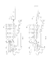
- Figure 1 best illustrates an exemplary control device 1 and receiver 2 of a control system 3 for use with one or more building power circuits (not shown in Figure 1 ).
- the control device which is defined by a control housing 4, is configured for receiving power from the building via wiring 5, and is also configured to provide power to at least one power output via wiring 6.
- the control device includes various control elements including a switch circuit 1a (such as one or more switching relays), a controller or circuit board 1b (which controls the switch circuit and perhaps the receiver/transceiver), and an auxiliary element 1c for providing auxiliary power to the controller 1b.
- a switch circuit 1a such as one or more switching relays
- a controller or circuit board 1b which controls the switch circuit and perhaps the receiver/transceiver
- an auxiliary element 1c for providing auxiliary power to the controller 1b.
- the receiver 2 of the system 3 is remote of the control device housing 4, and disposed in removable wired connection with the control device 1 via a flexible extension 7.
- This wired connection via extension 7 is removable in the sense that the extension 7 and housing 4 are configured for quick-connect/quick-disconnect plugging connection at port 8 of the housing 4.
- the receiver 2 and control device 1 of the system 3 are configured for plug-and-play connections, and any reference to "quick-connect/quick-disconnect plugging connection" in this disclosure can be defined as and synonymous with a plug-and-play connection.
- the receiver 2 which is a radio frequency receiver in an exemplary embodiment, is positionable independently of control device 1 by means of the flexible extension 7.
- control device 1, inclusive of switch circuit 1a to be disposed within any constructions (even those that are known to attenuate radio frequency signals such as the cavities of electrified modular office furniture systems and the like), and to be of electrically grounded metallic construction, and thus, to be configured as an integral part of a modular furniture wiring system.
- this allows receiver 2 to be disposed in a position favorable for receiving radio signals.
- the receiver 2 may be enclosed in a housing penetrable by radio frequency signals and include a radio receiver or transceiver and an associated antenna, or simply the antenna associated with an imbedded radio receiver.
- flexible extension 7 may be a shielded cable that prevents induced signals (such as radio signals) along its length, and plug-and-play connector 9 may be provided to facilitate connection and interchangeability of flexible extension 7 with the port 8 or other flexible connections that may vary in length or cable type or may include other receivers 2 of various form factors, radio sensitivities, signal directionalities, or the like.
- the extension 7 may be or configured to be of any length desirable for system use.
- control device 1 and receiver 2 of the system 3 as discussed above may be used in various configurations. These configurations will be discussed hereinbelow with reference to Figures 2-10 .
- FIG. 2 discloses control devices 10 and 11 (similar to the control device 1 shown in Figure 1 ), which each include the switch circuit 1a, controller 1b, and auxiliary element 1c discussed above.
- Each control device 10 and 11 is in wired in association with power output wiring 12 (similar to wiring 6 of Figure 1 ) so as to provide on/off control of circuits that may include one or more convenience power receptacles 13 in response to signals received at the controller from one or more sensors 14 (e.g. motion sensors) connected directly to the controller and/or via radio frequency transmissions from remote sensors, sensor networks, and/or building energy management systems received via plug-and-play receivers 15 (similar to the receiver 2 of Figure 1 ).
- Each of the control devices 10 and 11 is dedicated to switch a circuit and may provide analog 0-10V dimming control, whereby a control output 16 of the controller 11 is wired directly to a controllable ballast or driver 17 in a luminaire 18.
- a portable control device 30 (similar to the control device 1 of Figure 1 , but without the switch circuit 1a) in a control system is shown to be powered by a cord and a remote plug-in power supply 31.
- the control device 30 provides dimming control of one or more controllable luminaires 32 via controller 1b, plug-and-play connectors 34 and plug-and-play cable 35 in response to sensors 36 (e.g. motion sensors) connected to the control device 30 via plug-and-play connections 37 and/or via transmissions from remote sensors, sensor networks and/or building energy management systems received via a plug-and-play receiver 38 (similar to receiver 2 of Figure 1 ).
- This embodiment is particularly suitable for dimming portable luminaires (such as luminaire 32 in Figure 3 ) in response to available daylight.
- FIG 4 another portable control device 40 (similar to the control device 1 of Figure 1 ) in a control system is shown to be powered by a cord and plug 41.
- the control device 40 provides switching control of a single portable electrical appliance (such as portable luminaire 42) or a single circuit array of convenience power receptacles 43 typically found in portable office and classroom furniture via singular plug-and-play connector 47 and in response to transmissions from remote sensors, sensor networks and/or building energy management systems received via a plug-and-play radio receiver 44 (similar to the receiver 2 of Figure 1 ).
- a single portable electrical appliance such as portable luminaire 42
- a single circuit array of convenience power receptacles 43 typically found in portable office and classroom furniture
- a plug-and-play radio receiver 44 similar to the receiver 2 of Figure 1 .
- a portable control device 50 (similar to the control device 1 of Figure 1 ) in a control system is shown.
- the control device 50 is powered by a single cord and plug 51 and provides both unswitched power for one or more convenience power receptacles 52 (such as those provided in association with portable office furniture) via plug-and-play connector 53, and provides switching control of one or more similar convenience power receptacles 54 via switching relay 55 of switch circuit 1a and plug-and-play connector 56 in response to transmissions from remote sensors, sensor networks, and/or building energy management systems received via a plug-and-play receiver 57 (similar to receiver 2 of Figure 1 ).
- plug-and-play connectors 53 and 56 may be common power cord extension fittings or may be any connector configured to interface with modular receptacle arrays 52 and 54 in a portable furniture power system.
- Advantageous operation allows an appliance or plug load such as portable luminaire 58 to be switched on and off in response to local occupancy or time-of day signaling received by control device 50 via receiver 57 when said appliance, luminaire, or plug load is powered via one of the convenience outlets of receptacle array 54.
- FIG. 6 another exemplary embodiment of a control system is shown, wherein all items correspond to like numbered items in Figure 5 , and the plug-and-play connectors 53 and 56 are replaced by a single multi-circuit plug-and-play connector 61 that is configured to interface with multi-circuit modular wiring system 62.
- the system includes control device 50', which may be configured with an extended portion 63 that may constitute a multi-conductor cable assembly.
- FIG. 7 another exemplary embodiment of a system is shown, wherein all items correspond to like numbered items in Figures 5 and 6 , and plug-and-play connectors 71 are added to interface with one or more sensors 72 (e.g. motion sensors) such that control device 50" can provide switching control of receptacle array 54 in response to local sensor signals (e.g. motion sensing) in addition to, instead of, or in combination with radio frequency transmissions received via radio receiver 57.
- sensors 72 e.g. motion sensors
- local sensor signals e.g. motion sensing
- FIG 8 further illustrates another exemplary embodiment of a system is shown, wherein all items correspond to like numbered items in Figures 5-7 .
- the system includes control device 50"', (similar to the control device 1 of Figure 1 ), and plug-and-play connectors 82 being provided to interface with plug-and-play cable 83 to achieve dimming control of one or more controllable luminaires 84 in response to signals from local sensors 72 (e.g. motion sensors) in addition to, instead of, or in combination with radio frequency transmissions received via the receiver 57.
- local sensors 72 e.g. motion sensors
- control device 90 (similar to the control device 1 of Figure 1 ) is connected to multi-circuit building wiring 91 and provides both unswitched power for one or more convenience power receptacles 92 (such as those provided in association with portable office furniture) and switching control of one or more similar convenience power receptacles 93 via one or more switching relays 94 of switch circuit 1a in response to transmissions from remote sensors, sensor networks and/or building energy management systems received via a plug-and-play receiver 95 (similar to receiver 2 of Figure 1 ) and in response to signals from local sensors 97 (e.g. motion sensors) via plug-and-play connectors 96.
- control device 90 (similar to the control device 1 of Figure 1 ) is connected to multi-circuit building wiring 91 and provides both unswitched power for one or more convenience power receptacles 92 (such as those provided in association with portable office furniture) and switching control of one or more similar convenience power receptacles 93 via one or more switching relays 94 of switch circuit 1a in response
- control device 90 may be configured to connect to a modular wiring system 98 via associating multi-circuit connectors 85 and 86, said connectors configured to associate one or more of the modular wiring system circuits 98 with switching relays 94 of controller 90 while connecting one or more of the modular wiring system circuits 98 directly to the building wiring 91 thereby providing a desirable mix of controlled convenience power receptacles 93 and uncontrolled convenience power receptacles 92.
- Advantageous operation allows an appliance or plug load such as portable luminaire 87 to be switched on and off in response to local occupancy or time-of-day signaling received by control device 90 via receiver 95 when said appliance, luminaire or plug load is powered via one of the convenience outlets of receptacle array 93.
- Figure 9 also reveals that control device 90 may be configured with extended portion 88, extended portion 89, or both, which may constitute a multi-conductor cable assembly.
- Figure 10 discloses another exemplary embodiment of a control system wherein all items correspond to like numbered items in Figure 9 .
- the system includes a control device 90' (similar to control device 1 of Figure 1 ) and plug-and-play connector 101 that is provided to interface with plug-and-play cable 102 to achieve dimming control of one or more controllable luminaires 87 in response to signals from local sensors 97 (e.g. motion sensors) in addition to, instead of, or in combination with radio frequency transmissions received via the receiver 95.
- local sensors 97 e.g. motion sensors
- FIG. 11 another exemplary embodiment of a control system 110 is illustrated.
- the control device 1 and receiver 2 shown in Figure 1 are replaced by a first control device portion 112 disposed remotely of a second control device portion 114.
- the first control device portion 112 and second control device portion 114 could replace any of the control devices and receivers (respectively) of Figures 1-10 .
- the first control device portion 112 which is defined by a first portion housing 116, is configured for receiving power from the building via wiring 118, and is also configured to provide switched and unswitched power to at least one power output 120, 120a via wiring 122, 122a (the power outputs 120, 120a further provide power to plug load devices and portable luminaires such as luminaire 124).
- the first control device portion 112 also includes a switch circuit 126 (like circuit 1a of Figures 1-10 ) and auxiliary power supply 128 (like supply 1c of Figures 1-10 ) housed within the first portion housing 116.
- the switch circuit 126 allows the wiring 122a to provide switched power to the power outputs 120 a (while outputs 120 receive unswitched power from output wiring 122).
- a controller or circuit board 130 Connected to the switch circuit 126 and auxiliary power supply 128 is a controller or circuit board 130 (like controller 1b of Figures 1-10 ).
- the controller 130 is disposed in the second control device portion 114 as defined by second portion housing 132.
- the controller 130 is connected to and receives signals from a radio frequency receiver 134 disposed within the second portion housing 132 or at least partially extending from the second portion housing 132 (for example via an antenna). Due to the nature of radio frequency signals, transmissions received by the receiver 134 and provided to the controller 130 may originate from devices located long distances from the controller 130 and luminaire(s) 124 and/or from devices that are separated from controller 130 by objects or constructions that are penetrable by radio frequency signals but cannot be penetrated by other signal types (e.g.
- the controller 130 may also receive signals from various sensors 136 (such as the wired, plug-and-play occupancy sensors plugged into the second control device portion 114 in Figure 11 ), and send signals directly to the luminaire(s) 124 (such as to a controllable ballast 137 of a luminaire). This transmission of signals to the luminaire(s) 124 may occur via a wired plug-and-play connection as shown in Figure 11 , or via a wireless transmission from the receiver 134 should the receiver 134 be configured as a transceiver (which is contemplated by this disclosure).
- any input received by the controller 130 may be transmitted to other control system receivers (such as any of the receivers identified in the above described embodiments) deployed within radio signal range of receiver/transceiver 134, to control plug load power outlets connected thereto.
- Figure 11 shows the first control device portion 112 and the second control device portion 114 (and elements disposed therewith/therein) to connect and communicate via a plug-and-play wired extension 138 similar to the extension 7 of Figure 1 .
- this wired extension may also be more permanently associated with the first control device portion 112 and the second control device portion 114, such that the connection would not be considered a plug-and-play connection.
- the aforementioned receiver may be a transceiver capable of transmitting signals from the controllers to other wireless enabled devices and/or building energy management systems.
Landscapes
- Engineering & Computer Science (AREA)
- Computer Networks & Wireless Communication (AREA)
- Power Engineering (AREA)
- Circuit Arrangement For Electric Light Sources In General (AREA)
- Selective Calling Equipment (AREA)
- Remote Monitoring And Control Of Power-Distribution Networks (AREA)
Applications Claiming Priority (1)
| Application Number | Priority Date | Filing Date | Title |
|---|---|---|---|
| US201261608484P | 2012-03-08 | 2012-03-08 |
Publications (2)
| Publication Number | Publication Date |
|---|---|
| EP2637483A2 true EP2637483A2 (de) | 2013-09-11 |
| EP2637483A3 EP2637483A3 (de) | 2015-03-04 |
Family
ID=48049758
Family Applications (1)
| Application Number | Title | Priority Date | Filing Date |
|---|---|---|---|
| EP20130158325 Withdrawn EP2637483A3 (de) | 2012-03-08 | 2013-03-08 | Steuerungssystem zur Verwendung mit einem oder mehreren Gebäudestromkreisen |
Country Status (3)
| Country | Link |
|---|---|
| US (3) | US9236738B2 (de) |
| EP (1) | EP2637483A3 (de) |
| CA (1) | CA2808928A1 (de) |
Families Citing this family (4)
| Publication number | Priority date | Publication date | Assignee | Title |
|---|---|---|---|---|
| US9236738B2 (en) * | 2012-03-08 | 2016-01-12 | Sylvan R. Shemitz Designs, Llc | Control system for use with one or more building power circuits |
| CN106332382A (zh) * | 2015-06-18 | 2017-01-11 | 东林科技股份有限公司 | 有线/无线控制系统及其数据桥接方法 |
| TWI575906B (zh) * | 2015-06-18 | 2017-03-21 | 東林科技股份有限公司 | 有線/無線控制系統及其資料橋接方法 |
| CN208141596U (zh) * | 2018-04-28 | 2018-11-23 | 施耐德电气(澳大利亚)有限公司 | 用于开关的信号装置 |
Family Cites Families (16)
| Publication number | Priority date | Publication date | Assignee | Title |
|---|---|---|---|---|
| DE29814109U1 (de) | 1998-08-06 | 1998-11-12 | Arnold, Frank, 76448 Durmersheim | Gesteuerte Steckdose (Steckdosenleiste) mit Dämmerungsschalter |
| US6379164B1 (en) | 2000-05-08 | 2002-04-30 | Ronald G. Cash, Jr. | System and method for configuring electrical receptacles |
| US20040224562A1 (en) * | 2003-02-14 | 2004-11-11 | Dolinshek Thomas J. | Three-way connector |
| US6995525B2 (en) * | 2003-11-13 | 2006-02-07 | Barthelmess Peter W | Light display with color and clear lights |
| GB0507531D0 (en) | 2005-04-14 | 2005-05-18 | Green Roger | Power saving device |
| US8214061B2 (en) | 2006-05-26 | 2012-07-03 | Abl Ip Holding Llc | Distributed intelligence automated lighting systems and methods |
| US7812543B2 (en) * | 2006-11-15 | 2010-10-12 | Budike Jr Lothar E S | Modular wireless lighting control system using a common ballast control interface |
| CA2721929A1 (en) * | 2008-04-22 | 2009-10-29 | Belkin International, Inc. | Relocatable power tap |
| US8228184B2 (en) | 2008-09-03 | 2012-07-24 | Lutron Electronics Co., Inc. | Battery-powered occupancy sensor |
| US8258654B2 (en) | 2009-07-15 | 2012-09-04 | Leviton Manufacturing Co., Inc. | Wireless occupancy sensing with portable power switching |
| US8946924B2 (en) | 2009-07-30 | 2015-02-03 | Lutron Electronics Co., Inc. | Load control system that operates in an energy-savings mode when an electric vehicle charger is charging a vehicle |
| AU2010101028B4 (en) | 2009-09-02 | 2011-03-31 | Mort Bay Traders Pty Ltd | An energy saving sensor apparatus |
| FR2949916B1 (fr) * | 2009-09-08 | 2016-07-22 | Jerome Gilbert | Dispositif, pour deconnecter au moins un appareil du reseau electrique, qui offre au moins un mode de fonctionnement en derogation, dispositif configurable, systeme et procede de configuration. |
| US8258412B2 (en) | 2009-10-29 | 2012-09-04 | Group Dekko, Inc. | Switchable electrical power system |
| US8749093B2 (en) * | 2010-06-09 | 2014-06-10 | Powertech Industrial Co., Ltd. | Electric receptacle module |
| US9236738B2 (en) * | 2012-03-08 | 2016-01-12 | Sylvan R. Shemitz Designs, Llc | Control system for use with one or more building power circuits |
-
2013
- 2013-03-06 US US13/786,960 patent/US9236738B2/en not_active Expired - Fee Related
- 2013-03-07 CA CA 2808928 patent/CA2808928A1/en not_active Abandoned
- 2013-03-08 EP EP20130158325 patent/EP2637483A3/de not_active Withdrawn
-
2015
- 2015-12-27 US US14/979,455 patent/US20160141871A1/en not_active Abandoned
-
2017
- 2017-11-01 US US15/801,292 patent/US20180123342A1/en not_active Abandoned
Non-Patent Citations (1)
| Title |
|---|
| None |
Also Published As
| Publication number | Publication date |
|---|---|
| CA2808928A1 (en) | 2013-09-08 |
| US20140077728A1 (en) | 2014-03-20 |
| US20180123342A1 (en) | 2018-05-03 |
| US20160141871A1 (en) | 2016-05-19 |
| US9236738B2 (en) | 2016-01-12 |
| EP2637483A3 (de) | 2015-03-04 |
Similar Documents
| Publication | Publication Date | Title |
|---|---|---|
| US20180123342A1 (en) | Control system for use with one or more building power circuits | |
| EP3047494B1 (de) | Leicht zu installierender automatisierter wohnungslichtschalter | |
| GB2445990B (en) | Pilot signal transmission in a radio communication system | |
| US20140103742A1 (en) | Connector having wireless control capabilities | |
| US10182510B2 (en) | Automation module for building automation | |
| CN105052007A (zh) | Dc配电系统 | |
| US20180292791A1 (en) | Modular Load Control | |
| US20130106199A1 (en) | Master slave radio control system | |
| EP2907151B1 (de) | Verbinder mit drahtlosen steuerungsfunktionen | |
| US20130086291A1 (en) | Switching logic module | |
| WO2017192806A1 (en) | Control system for workstation luminaires and plug load receptacles | |
| US9520742B2 (en) | Monitoring system and method | |
| EP2973885B1 (de) | Drahtlosverbinderknoten und system | |
| US20170346336A1 (en) | Outlet control system | |
| US20140049107A1 (en) | Intelligent Lighting and Electrical System | |
| EP2160077B1 (de) | Modulares Rangiersystem | |
| KR20150096057A (ko) | 블루투스를 이용한 조명 제어 시스템 | |
| EP3258647A1 (de) | Kombinierte verdrahtete und drahtlose steuerung in einem gebäudeautomatisierungssystem | |
| BE1022848B1 (nl) | Elektrisch systeem voor installatie in een gebouw | |
| JP7077777B2 (ja) | 照明器具 | |
| EP2793323A1 (de) | Steckdose mit drahtlosen Steuerungsfunktionen | |
| US20190204795A1 (en) | Communication System for Power Outlet Control Devices | |
| CN205809683U (zh) | 一种具有集成控制器的系统 | |
| JP2016152090A (ja) | 照明器具及び照明システム | |
| JP2019121504A (ja) | 設置フリースイッチ装置 |
Legal Events
| Date | Code | Title | Description |
|---|---|---|---|
| PUAI | Public reference made under article 153(3) epc to a published international application that has entered the european phase |
Free format text: ORIGINAL CODE: 0009012 |
|
| AK | Designated contracting states |
Kind code of ref document: A2 Designated state(s): AL AT BE BG CH CY CZ DE DK EE ES FI FR GB GR HR HU IE IS IT LI LT LU LV MC MK MT NL NO PL PT RO RS SE SI SK SM TR |
|
| AX | Request for extension of the european patent |
Extension state: BA ME |
|
| PUAL | Search report despatched |
Free format text: ORIGINAL CODE: 0009013 |
|
| AK | Designated contracting states |
Kind code of ref document: A3 Designated state(s): AL AT BE BG CH CY CZ DE DK EE ES FI FR GB GR HR HU IE IS IT LI LT LU LV MC MK MT NL NO PL PT RO RS SE SI SK SM TR |
|
| AX | Request for extension of the european patent |
Extension state: BA ME |
|
| RIC1 | Information provided on ipc code assigned before grant |
Ipc: H05B 37/02 20060101AFI20150129BHEP |
|
| RAP1 | Party data changed (applicant data changed or rights of an application transferred) |
Owner name: SYLVAN R. SHEMITZ DESIGNS, LLC |
|
| STAA | Information on the status of an ep patent application or granted ep patent |
Free format text: STATUS: THE APPLICATION IS DEEMED TO BE WITHDRAWN |
|
| 18D | Application deemed to be withdrawn |
Effective date: 20150905 |