EP2637419A1 - Electronic device - Google Patents
Electronic device Download PDFInfo
- Publication number
- EP2637419A1 EP2637419A1 EP11837698.7A EP11837698A EP2637419A1 EP 2637419 A1 EP2637419 A1 EP 2637419A1 EP 11837698 A EP11837698 A EP 11837698A EP 2637419 A1 EP2637419 A1 EP 2637419A1
- Authority
- EP
- European Patent Office
- Prior art keywords
- sound
- electronic apparatus
- ultrasonic wave
- control unit
- oscillation device
- Prior art date
- Legal status (The legal status is an assumption and is not a legal conclusion. Google has not performed a legal analysis and makes no representation as to the accuracy of the status listed.)
- Granted
Links
Images



Classifications
-
- H—ELECTRICITY
- H04—ELECTRIC COMMUNICATION TECHNIQUE
- H04N—PICTORIAL COMMUNICATION, e.g. TELEVISION
- H04N5/00—Details of television systems
- H04N5/44—Receiver circuitry for the reception of television signals according to analogue transmission standards
- H04N5/60—Receiver circuitry for the reception of television signals according to analogue transmission standards for the sound signals
-
- H—ELECTRICITY
- H04—ELECTRIC COMMUNICATION TECHNIQUE
- H04N—PICTORIAL COMMUNICATION, e.g. TELEVISION
- H04N21/00—Selective content distribution, e.g. interactive television or video on demand [VOD]
- H04N21/40—Client devices specifically adapted for the reception of or interaction with content, e.g. set-top-box [STB]; Operations thereof
- H04N21/41—Structure of client; Structure of client peripherals
- H04N21/422—Input-only peripherals, i.e. input devices connected to specially adapted client devices, e.g. global positioning system [GPS]
- H04N21/42202—Input-only peripherals, i.e. input devices connected to specially adapted client devices, e.g. global positioning system [GPS] environmental sensors, e.g. for detecting temperature, luminosity, pressure, earthquakes
-
- H—ELECTRICITY
- H04—ELECTRIC COMMUNICATION TECHNIQUE
- H04N—PICTORIAL COMMUNICATION, e.g. TELEVISION
- H04N21/00—Selective content distribution, e.g. interactive television or video on demand [VOD]
- H04N21/40—Client devices specifically adapted for the reception of or interaction with content, e.g. set-top-box [STB]; Operations thereof
- H04N21/43—Processing of content or additional data, e.g. demultiplexing additional data from a digital video stream; Elementary client operations, e.g. monitoring of home network or synchronising decoder's clock; Client middleware
- H04N21/439—Processing of audio elementary streams
-
- H—ELECTRICITY
- H04—ELECTRIC COMMUNICATION TECHNIQUE
- H04R—LOUDSPEAKERS, MICROPHONES, GRAMOPHONE PICK-UPS OR LIKE ACOUSTIC ELECTROMECHANICAL TRANSDUCERS; ELECTRIC HEARING AIDS; PUBLIC ADDRESS SYSTEMS
- H04R3/00—Circuits for transducers
-
- H—ELECTRICITY
- H04—ELECTRIC COMMUNICATION TECHNIQUE
- H04R—LOUDSPEAKERS, MICROPHONES, GRAMOPHONE PICK-UPS OR LIKE ACOUSTIC ELECTROMECHANICAL TRANSDUCERS; ELECTRIC HEARING AIDS; PUBLIC ADDRESS SYSTEMS
- H04R2217/00—Details of magnetostrictive, piezoelectric, or electrostrictive transducers covered by H04R15/00 or H04R17/00 but not provided for in any of their subgroups
- H04R2217/03—Parametric transducers where sound is generated or captured by the acoustic demodulation of amplitude modulated ultrasonic waves
-
- H—ELECTRICITY
- H04—ELECTRIC COMMUNICATION TECHNIQUE
- H04R—LOUDSPEAKERS, MICROPHONES, GRAMOPHONE PICK-UPS OR LIKE ACOUSTIC ELECTROMECHANICAL TRANSDUCERS; ELECTRIC HEARING AIDS; PUBLIC ADDRESS SYSTEMS
- H04R2499/00—Aspects covered by H04R or H04S not otherwise provided for in their subgroups
- H04R2499/10—General applications
- H04R2499/15—Transducers incorporated in visual displaying devices, e.g. televisions, computer displays, laptops
Definitions
- the present invention relates to an electronic apparatus.
- Patent Document 1 As a technology using an oscillation apparatus that oscillates an ultrasonic wave, for example, there is a speaker. As a technology related to the speaker using the ultrasonic wave, for example, there are disclosures in Patent Documents 1 to 3.
- the technology disclosed in Patent Document 1 is a technology configured so that sound associated with an image displayed on the screen is realized by a reflection wave of the ultrasonic wave transmitted toward the screen.
- Patent Documents 2 and 3 All of the technologies disclosed in Patent Documents 2 and 3 are configured so that the ultrasonic wave is oscillated toward an image plane in a projector on which the speaker using the ultrasonic wave is mounted.
- the technology disclosed in the Patent Document 2 is configured so that an ultrasonic wave speaker is disposed inside an intake duct of the projector.
- the technology disclosed in Patent Document 3 is configured so that an audio reproduction condition can be appropriately adjusted by varying a radiation direction of the ultrasonic wave, depending on a position of the projector.
- An objection of the invention is to achieve the decreased power consumption in electronic apparatuses.
- an electronic apparatus including: an image projection unit that projects an image plane: an oscillation device that oscillates an ultrasonic wave for sensors and an ultrasonic wave for an audio reproduction, toward the image plane: a control unit that controls the oscillation device: and a sound wave detection unit that is connected to the control unit, wherein the sound wave detection unit detects the ultrasonic wave for sensors, which is reflected from the image plane, and the control unit adjusts a sound pressure of a sound to be reproduced based on a detection strength detected by the sound wave detection unit.
- the ultrasonic wave for sensors which is reflected, is detected and the sound pressure is adjusted for a sound to be reproduced based on the detection strength. Therefore, corresponding to the audio reproduction environment, the sound can be reproduced by a suitable sound pressure. Accordingly, the decreased power consumption in electronic apparatuses can be achieved.
- the decreased power consumption in electronic apparatuses can be achieved.
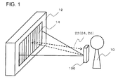
- FIG. 1 is a schematic view illustrating an operation method off an electronic apparatus 100 according to a first embodiment.
- the electronic apparatus 100 according to the embodiment includes an image projection unit 40, an oscillation device 20, an audio control unit 52 and a sound wave detection unit 30.
- the electronic apparatus 100 is, for example, a mobile terminal apparatus and more specifically, for example, a mobile phone.
- the image projection unit 40 projects images.
- the oscillation device 20 emits an ultrasonic wave 22 toward an image plane.
- the ultrasonic wave 22 includes an ultrasonic wave 24 for sensors and an ultrasonic wave 26 for audio reproduction.
- the audio control unit 52 controls the oscillation device 20.
- the sound wave detection unit 30 is connected to the audio control unit 52.
- the sound wave detection unit 30 detects the ultrasonic wave 24 for sensors, which is reflected from the image plane.
- the audio control unit 52 adjusts a sound pressure of a sound to be reproduced based on detection strength detected by the sound wave detection unit 30.
- a configuration of the electronic apparatus 100 will be given.
- the image plane is projected from the electronic apparatus 100 toward a display area 12.
- the ultrasonic wave 22 is oscillated from the electronic apparatus 100 toward the image plane 14 projected on the display area 12.
- the display area 12 may be, for example, a wall in a room, a projector screen or the like, but is not limited thereto.
- the ultrasonic wave 24 for sensors oscillated from the electronic apparatus 100 is reflected by the display area 12 and then detected by the sound wave detection unit 30 of the electronic apparatus 100.
- the ultrasonic wave 26 for audio reproduction oscillated from the electronic apparatus 100 is reflected by the display area 12 to form a sound field around a user 10. As a result, the sound is reproduced from the image plane 14 toward the user 10. Therefore, an acoustic function having a sense of realism can be realized.
- FIG. 2 is a block diagram illustrating a configuration of the electronic apparatus 100 illustrated in FIG. 1 .
- the electronic apparatus 100 further includes a housing 60, a control unit 50 and a video control unit 54.
- the image projection unit 40, the oscillation device 20, the sound wave detection unit 30, the audio control unit 52, the video control unit 54 and the control unit 50 are formed, for example, inside the housing 60.
- a hole through which the ultrasonic wave 22 oscillated from the oscillation device 20 passes and the other hole through which light projected from the image projection unit 40 passes are installed.
- the video control unit 54 controls the image projection unit 40.
- the control unit 50 is connected to both of the audio control unit 52 and the video control unit 54 to control them.
- the oscillation device 20 is installed in plural number in an array shape, for example.
- the oscillation device 20 that oscillates the ultrasonic wave 24 for sensors may be different from the oscillation device 20 that oscillates the ultrasonic wave 26 for audio reproduction or may be the same each other.
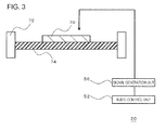
- FIG. 3 is a cross-sectional view illustrating the oscillation device 20 illustrated in FIG. 1 .
- the oscillation device 20 includes a piezoelectric vibrator 70, a support member 72 and a vibration member 74.
- the piezoelectric vibrator 70 is installed on one surface of the vibration member 74.
- the support member 72 supports an edge of the vibration member 74.
- the audio control unit 52 is connected to the piezoelectric vibrator 70 via a signal generation unit 56.
- the signal generation unit 56 generates an electric signal which is input to the piezoelectric vibrator 70.
- the audio control unit 52 controls the signal generation unit 56 based on information input from the outside and thereby controls the oscillation of the oscillation device.
- the audio control unit 52 inputs a modulation signal as a parametric speaker via the signal generation unit 56.
- the piezoelectric vibrator 70 uses a sound wave which is equal to or more than 20 KHz, for example, 100 KHz, as a signal of the carrier wave of the signal.
- the signal input to the audio control unit 52 is a command signal which commands the oscillation device 20 to oscillate the sound wave. Then, in a case where the oscillation device 20 is used as the sound wave sensor, the signal generation unit 56 causes the piezoelectric vibrator 70 to generate a sound wave of a resonance frequency of the piezoelectric vibrator 70.
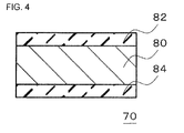
- FIG. 4 is a cross-sectional view illustrating the piezoelectric vibrator 70 illustrated in FIG. 3 .
- the piezoelectric vibrator 70 is formed of a piezoelectric body 80, an upper electrode 82 and a lower electrode 84.
- the piezoelectric vibrator 70 has, for example, a circular or oval shape when seen in a plan view.
- the piezoelectric body 80 is interposed between the upper electrode 82 and the lower electrode 84.
- the piezoelectric body 80 polarizes in the thickness direction.
- the piezoelectric body 80 is configured by a material having high piezoelectric effect.
- the piezoelectric body 80 is configured by a material with high electromechanical conversion efficiency such as a lead zirconate titanate (PZT) or a barium titanate (BaTiO 3 ).
- the thickness of the piezoelectric body 80 is preferably 10 ⁇ m to 1mm.
- the piezoelectric body 80 is configured by a brittle material. Therefore, in a case where the thickness is less than 10 micrometers, damage is likely to occur during the handling. On the other hand, in a case where the thickness exceeds 1 mm, an electric field strength of the piezoelectric body 80 is decreased. Accordingly, energy conversion efficiency in the piezoelectric vibrator 70 results in degradation.
- the upper electrode 82 and the lower electrode 84 are configured by a material having an electric conductivity.
- the upper electrode 82 and the lower electrode 84 are configured by silver or an alloy of silver and palladium, for example.
- the silver is a general use material having a low resistivity. Therefore, when the upper electrode 82 and the lower electrode 84 are configured by the silver, a superior electrode in view of the manufacturing cost and manufacturing process can be realized.
- the alloy of silver and palladium is a low resistance material having an excellent resistance to oxidation. Therefore, when the upper electrode 82 and the lower electrode 84 are configured by the alloy of silver and palladium, a highly reliable electrode can be realized.
- the thickness of the upper electrode 82 and the lower electrode 84 is preferably 1 to 50 ⁇ m.
- the thickness is less than 1 ⁇ m, it is difficult to uniformly mold the upper electrode 82 and the lower electrode 84. On the other hand, if the thickness exceeds 50 ⁇ m, the upper electrode 82 or the lower electrode 84 become a restraint surface with respect to the piezoelectric body 80. Therefore, the degradation of the energy conversion efficiency is occurred in the piezoelectric vibrator 70.
- the vibration member 74 is configured by a material having high elastic modulus such as a metal or a resin compared to a ceramic which is the brittle material.
- the vibration member 74 is configured by a general purpose material such as phosphor bronze or stainless, for example.
- the thickness of the vibration member 74 is preferably 5 to 500 ⁇ m.
- the vertical elastic modulus of the vibration member 74 is preferably 1 to 500GPa. In a case where the vertical elastic modulus of the vibration member 74 is excessively low or high, properties or reliability as the mechanical vibrator is likely to be impaired.
- the sound wave detection unit 30 determines that the ultrasonic wave 24 for sensors is detected, for example, when it is verified that a frequency of the detected sound wave is a frequency within a certain range and the strength of the detected sound wave is equal to or more than a reference value. Thereby, a noise from an ambient environment and the ultrasonic wave 24 for sensors can be distinguished from each other.
- the sound wave detection unit 30 can be configured by a microphone, for example.
- the audio control unit 52 adjusts the sound pressure of the reproduced sound to be lower, for example, when the strength of the reflected ultrasonic wave 24 for sensors from the display area 12 is high. In addition, for example, when the strength of the ultrasonic wave 24 for sensors, which is reflected from the display area 12, is low, the sound pressure of the reproducing sound is adjusted to be higher. The adjustment is performed based on, for example, a relational expression or table indicating a predetermined correlation between a detection strength and a reproducing sound pressure. The audio control unit 52 holds, for example, the data of these relational expression and table in advance.
- the sound reproduction is performed using an operation principle of the parametric speaker.
- the operation principle of the parametric speaker is as follows.
- the operation principle of the parametric speaker is to perform the sound reproduction using such a principle that the audible sound is present by nonlinear characteristics when the ultrasonic wave subjected to an AM modulation, a DSB modulation, a SSB modulation and an FM modulation is emitted in the air and then the emitted ultrasonic wave is propagated in the air.
- so called non-linear characteristics indicate a transition from a layer flow to a turbulent flow when Reynolds number represented by a ratio between inertial effects and viscous effects is increased.
- the sound wave is slightly disturbed inside a fluid, the sound wave is propagated in a non-linear manner. Particularly, when the ultrasonic wave is emitted in the air, a harmonic wave is remarkably generated due to the non-linear manner.
- the sound wave is in a sparse and dense state in which molecular groups are sparsely and densely mixed in the air. If it takes more time to restore the air molecule than to compress it, the air which is not restored after being compressed collides with the continuously propagated air and thereby a shock wave is generated. As a result, the audible sound is generated. Since the parametric speaker can form the sound field only around the user, the parametric speaker is excellent in a viewpoint of privacy protection.
- FIG. 5 is a flow chart illustrating the operation method of the electronic apparatus 100 illustrated in FIG. 1 .
- the ultrasonic wave 24 for sensors is oscillated from the oscillation device 20 toward the display area 12 (S11). Then, the ultrasonic wave 24 for sensors reflected from the display area 12 is detected by the sound wave detection unit 30 (S12). If the ultrasonic wave 24 for sensors is detected, the detection strength thereof is measured (S13). If the detection strength is high, the sound pressure of the reproducing sound is adjusted to be lower. In addition, if the detection strength is low, the sound pressure of the reproducing sound is adjusted to be higher (S14).
- Such adjustment is performed based on, for example, a predetermined correlation between the detection strength and the reproducing sound pressure.
- the image plane 14 is projected on the display area 12 by the image projection unit 40 (S15).
- the ultrasonic wave 26 for audio reproduction is oscillated (S16).
- the sound pressure of the reproducing sound is adjusted based on the detection strength after detection of the reflected ultrasonic wave 24 for sensors. Therefore, the electronic apparatus 100 can represent the sound with an appropriate sound pressure in response to various environments representing the sound, such as materials of the display area 12 which causes the ultrasonic wave 26 for audio reproduction to be reflected, a distance between the user 10 and the display area 12, and the like. Therefore, decreased power consumption in the electronic apparatuses can be achieved.
- the electronic apparatus 100 is a mobile terminal device
- the environment projecting the image is varies.
- the effects described above become particularly noticeable.
- the sound image is formed by the ultrasonic wave 26 for audio reproduction which is reflected from the image plane 14. Therefore, the user 10 has a feeling such that the sound is reproduced from the image plane 14. Thus, it is possible to form a sound image with a sense of realism.
- the oscillation device 20 configures the parametric speaker. Therefore, the sound field can be formed only around the user 10. Thus, a superior electronic apparatus can be realized in the view point of privacy protection.
- FIG. 6 is an exploded perspective view illustrating a vibrator of the oscillation device 20 configuring an electronic apparatus according to a second embodiment.
- the vibrator of the oscillation device 20 according to the second embodiment is configured by a MEMS actuator 90. Except for such a point, the electronic apparatus according to the present embodiment is the same as the electronic apparatus according to the first embodiment.
- a driving method of the MEMS actuator 90 is a piezoelectric method and has a structure in which a piezoelectric thin film layer 92 is interposed between an upper movable electrode 94 and a lower movable electrode 96.
- the MEMS actuator 90 is operated by inputting a signal from the signal generation unit 56 to an upper movable electrode layer 94 and a lower movable electrode layer 96.
- an aerosol deposition method is used when manufacturing the MEMS actuator 90, but the manufacturing method is not limited thereto.
- the piezoelectric thin film layer 92, the upper movable electrode layer 94 and the lower movable electrode layer 96 can be respectively deposited on a curved surface as well.
- the driving method of the MEMS actuator 90 may be an electrostatic method, an electromagnetic method or a heat conduction method.
Landscapes
- Engineering & Computer Science (AREA)
- Signal Processing (AREA)
- Multimedia (AREA)
- Business, Economics & Management (AREA)
- Physics & Mathematics (AREA)
- Life Sciences & Earth Sciences (AREA)
- Biodiversity & Conservation Biology (AREA)
- Ecology (AREA)
- Emergency Management (AREA)
- Environmental & Geological Engineering (AREA)
- Environmental Sciences (AREA)
- Remote Sensing (AREA)
- Acoustics & Sound (AREA)
- Circuit For Audible Band Transducer (AREA)
- Transducers For Ultrasonic Waves (AREA)
- Television Receiver Circuits (AREA)
Abstract
Description
- The present invention relates to an electronic apparatus.
- As a technology using an oscillation apparatus that oscillates an ultrasonic wave, for example, there is a speaker. As a technology related to the speaker using the ultrasonic wave, for example, there are disclosures in Patent Documents 1 to 3. The technology disclosed in Patent Document 1 is a technology configured so that sound associated with an image displayed on the screen is realized by a reflection wave of the ultrasonic wave transmitted toward the screen.
- All of the technologies disclosed in Patent Documents 2 and 3 are configured so that the ultrasonic wave is oscillated toward an image plane in a projector on which the speaker using the ultrasonic wave is mounted. The technology disclosed in the Patent Document 2 is configured so that an ultrasonic wave speaker is disposed inside an intake duct of the projector. In addition, the technology disclosed in Patent Document 3 is configured so that an audio reproduction condition can be appropriately adjusted by varying a radiation direction of the ultrasonic wave, depending on a position of the projector.
-
- [Patent Document 1] Japanese Unexamined Patent Publication No.
2000-23281 - [Patent Document 2] Japanese Unexamined Patent Publication No.
2006-5552 - [Patent Document 3] Japanese Unexamined Patent Publication No.
2007-43585 - As is in the Patent Documents 2 and 3, there is a technology configured so that an ultrasonic wave is oscillated toward an image plane projected by a projector and thus audio is reproduced by a reflection wave. However, an audio reproduction environment also varies depending on an image projection environment. Therefore, corresponding to the audio reproduction environment, it has been desirable not only to reproduce the audio having a suitable sound pressure but also to achieve the decreased power consumption in electronic apparatuses.
- An objection of the invention is to achieve the decreased power consumption in electronic apparatuses.
- According to an aspect of the invention, there is provided an electronic apparatus including: an image projection unit that projects an image plane: an oscillation device that oscillates an ultrasonic wave for sensors and an ultrasonic wave for an audio reproduction, toward the image plane: a control unit that controls the oscillation device: and a sound wave detection unit that is connected to the control unit, wherein the sound wave detection unit detects the ultrasonic wave for sensors, which is reflected from the image plane, and the control unit adjusts a sound pressure of a sound to be reproduced based on a detection strength detected by the sound wave detection unit.
- According to the invention, the ultrasonic wave for sensors, which is reflected, is detected and the sound pressure is adjusted for a sound to be reproduced based on the detection strength. Therefore, corresponding to the audio reproduction environment, the sound can be reproduced by a suitable sound pressure. Accordingly, the decreased power consumption in electronic apparatuses can be achieved.
- According to the invention, the decreased power consumption in electronic apparatuses can be achieved.
- The above-described object and other object, characteristics and advantages will be further apparent from preferred embodiments described below and the accompanying drawings as follows:
-
-
FIG. 1 is a schematic view illustrating an operation method of an electronic apparatus according to a first embodiment. -
FIG. 2 is a block diagram illustrating a configuration of the electronic apparatus illustrated inFIG. 1 . -
FIG. 3 is a cross-sectional view illustrating an oscillation device illustrated inFIG. 1 . -
FIG. 4 is a cross-sectional view illustrating a piezoelectric vibrator illustrated inFIG. 3 . -
FIG. 5 is a flow chart illustrating an operation method of the electronic apparatus illustrated inFIG. 1 . -
FIG. 6 is an exploded perspective view illustrating a vibrator of an oscillation device configuring an electronic apparatus according to a second embodiment. - Hereinafter, embodiments of the invention will be described with reference to the drawings accompanying herewith. In addition, in all of the drawings, similar reference numerals are given to similar configuration elements and the description thereof will not be repeated.
-
FIG. 1 is a schematic view illustrating an operation method off anelectronic apparatus 100 according to a first embodiment. Theelectronic apparatus 100 according to the embodiment includes animage projection unit 40, anoscillation device 20, anaudio control unit 52 and a soundwave detection unit 30. Theelectronic apparatus 100 is, for example, a mobile terminal apparatus and more specifically, for example, a mobile phone. - The image projection unit 40 projects images. The
oscillation device 20 emits anultrasonic wave 22 toward an image plane. Theultrasonic wave 22 includes an ultrasonic wave 24 for sensors and an ultrasonic wave 26 for audio reproduction. Theaudio control unit 52 controls theoscillation device 20. The soundwave detection unit 30 is connected to theaudio control unit 52. The soundwave detection unit 30 detects the ultrasonic wave 24 for sensors, which is reflected from the image plane. Theaudio control unit 52 adjusts a sound pressure of a sound to be reproduced based on detection strength detected by the soundwave detection unit 30. Hereinafter, a detailed description with regard to a configuration of theelectronic apparatus 100 will be given. - As illustrated in
FIG. 1 , the image plane is projected from theelectronic apparatus 100 toward adisplay area 12. Then, theultrasonic wave 22 is oscillated from theelectronic apparatus 100 toward theimage plane 14 projected on thedisplay area 12. Thedisplay area 12 may be, for example, a wall in a room, a projector screen or the like, but is not limited thereto. The ultrasonic wave 24 for sensors oscillated from theelectronic apparatus 100 is reflected by thedisplay area 12 and then detected by the soundwave detection unit 30 of theelectronic apparatus 100. In addition, the ultrasonic wave 26 for audio reproduction oscillated from theelectronic apparatus 100 is reflected by thedisplay area 12 to form a sound field around auser 10. As a result, the sound is reproduced from theimage plane 14 toward theuser 10. Therefore, an acoustic function having a sense of realism can be realized. -
FIG. 2 is a block diagram illustrating a configuration of theelectronic apparatus 100 illustrated inFIG. 1 . As illustrated inFIG. 2 , theelectronic apparatus 100 further includes ahousing 60, acontrol unit 50 and avideo control unit 54. Theimage projection unit 40, theoscillation device 20, the soundwave detection unit 30, theaudio control unit 52, thevideo control unit 54 and thecontrol unit 50 are formed, for example, inside thehousing 60. In thehousing 60, a hole through which theultrasonic wave 22 oscillated from theoscillation device 20 passes and the other hole through which light projected from theimage projection unit 40 passes are installed. Thevideo control unit 54 controls theimage projection unit 40. Thecontrol unit 50 is connected to both of theaudio control unit 52 and thevideo control unit 54 to control them. Theoscillation device 20 is installed in plural number in an array shape, for example. Theoscillation device 20 that oscillates the ultrasonic wave 24 for sensors may be different from theoscillation device 20 that oscillates the ultrasonic wave 26 for audio reproduction or may be the same each other. -
FIG. 3 is a cross-sectional view illustrating theoscillation device 20 illustrated inFIG. 1 . Theoscillation device 20 includes apiezoelectric vibrator 70, asupport member 72 and avibration member 74. Thepiezoelectric vibrator 70 is installed on one surface of thevibration member 74. Thesupport member 72 supports an edge of thevibration member 74. - The
audio control unit 52 is connected to thepiezoelectric vibrator 70 via asignal generation unit 56. Thesignal generation unit 56 generates an electric signal which is input to thepiezoelectric vibrator 70. Theaudio control unit 52 controls thesignal generation unit 56 based on information input from the outside and thereby controls the oscillation of the oscillation device. In a case where theoscillation device 20 is used as the speaker, theaudio control unit 52 inputs a modulation signal as a parametric speaker via thesignal generation unit 56. In this case, thepiezoelectric vibrator 70 uses a sound wave which is equal to or more than 20 KHz, for example, 100 KHz, as a signal of the carrier wave of the signal. In addition, in a case where theoscillation device 20 is used as a sound wave sensor, the signal input to theaudio control unit 52 is a command signal which commands theoscillation device 20 to oscillate the sound wave. Then, in a case where theoscillation device 20 is used as the sound wave sensor, thesignal generation unit 56 causes thepiezoelectric vibrator 70 to generate a sound wave of a resonance frequency of thepiezoelectric vibrator 70. -
FIG. 4 is a cross-sectional view illustrating thepiezoelectric vibrator 70 illustrated inFIG. 3 . As illustrated inFIG. 4 , thepiezoelectric vibrator 70 is formed of apiezoelectric body 80, anupper electrode 82 and alower electrode 84. In addition, thepiezoelectric vibrator 70 has, for example, a circular or oval shape when seen in a plan view. Thepiezoelectric body 80 is interposed between theupper electrode 82 and thelower electrode 84. In addition, thepiezoelectric body 80 polarizes in the thickness direction. Thepiezoelectric body 80 is configured by a material having high piezoelectric effect. For example, thepiezoelectric body 80 is configured by a material with high electromechanical conversion efficiency such as a lead zirconate titanate (PZT) or a barium titanate (BaTiO3). In addition, the thickness of thepiezoelectric body 80 is preferably 10 µm to 1mm. Thepiezoelectric body 80 is configured by a brittle material. Therefore, in a case where the thickness is less than 10 micrometers, damage is likely to occur during the handling. On the other hand, in a case where the thickness exceeds 1 mm, an electric field strength of thepiezoelectric body 80 is decreased. Accordingly, energy conversion efficiency in thepiezoelectric vibrator 70 results in degradation. - The
upper electrode 82 and thelower electrode 84 are configured by a material having an electric conductivity. Theupper electrode 82 and thelower electrode 84 are configured by silver or an alloy of silver and palladium, for example. The silver is a general use material having a low resistivity. Therefore, when theupper electrode 82 and thelower electrode 84 are configured by the silver, a superior electrode in view of the manufacturing cost and manufacturing process can be realized. In addition, the alloy of silver and palladium is a low resistance material having an excellent resistance to oxidation. Therefore, when theupper electrode 82 and thelower electrode 84 are configured by the alloy of silver and palladium, a highly reliable electrode can be realized.
The thickness of theupper electrode 82 and thelower electrode 84 is preferably 1 to 50µm. If the thickness is less than 1µm, it is difficult to uniformly mold theupper electrode 82 and thelower electrode 84. On the other hand, if the thickness exceeds 50µm, theupper electrode 82 or thelower electrode 84 become a restraint surface with respect to thepiezoelectric body 80. Therefore, the degradation of the energy conversion efficiency is occurred in thepiezoelectric vibrator 70. - The
vibration member 74 is configured by a material having high elastic modulus such as a metal or a resin compared to a ceramic which is the brittle material. Thevibration member 74 is configured by a general purpose material such as phosphor bronze or stainless, for example. The thickness of thevibration member 74 is preferably 5 to 500µm. In addition, the vertical elastic modulus of thevibration member 74 is preferably 1 to 500GPa. In a case where the vertical elastic modulus of thevibration member 74 is excessively low or high, properties or reliability as the mechanical vibrator is likely to be impaired. - The sound
wave detection unit 30 determines that the ultrasonic wave 24 for sensors is detected, for example, when it is verified that a frequency of the detected sound wave is a frequency within a certain range and the strength of the detected sound wave is equal to or more than a reference value. Thereby, a noise from an ambient environment and the ultrasonic wave 24 for sensors can be distinguished from each other. When theelectronic apparatus 100 is a mobile phone, the soundwave detection unit 30 can be configured by a microphone, for example. - The
audio control unit 52 adjusts the sound pressure of the reproduced sound to be lower, for example, when the strength of the reflected ultrasonic wave 24 for sensors from thedisplay area 12 is high. In addition, for example, when the strength of the ultrasonic wave 24 for sensors, which is reflected from thedisplay area 12, is low, the sound pressure of the reproducing sound is adjusted to be higher. The adjustment is performed based on, for example, a relational expression or table indicating a predetermined correlation between a detection strength and a reproducing sound pressure. Theaudio control unit 52 holds, for example, the data of these relational expression and table in advance. - In the present embodiment, the sound reproduction is performed using an operation principle of the parametric speaker. The operation principle of the parametric speaker is as follows. The operation principle of the parametric speaker is to perform the sound reproduction using such a principle that the audible sound is present by nonlinear characteristics when the ultrasonic wave subjected to an AM modulation, a DSB modulation, a SSB modulation and an FM modulation is emitted in the air and then the emitted ultrasonic wave is propagated in the air. Here, so called non-linear characteristics indicate a transition from a layer flow to a turbulent flow when Reynolds number represented by a ratio between inertial effects and viscous effects is increased. That is, since the sound wave is slightly disturbed inside a fluid, the sound wave is propagated in a non-linear manner. Particularly, when the ultrasonic wave is emitted in the air, a harmonic wave is remarkably generated due to the non-linear manner. In addition, the sound wave is in a sparse and dense state in which molecular groups are sparsely and densely mixed in the air. If it takes more time to restore the air molecule than to compress it, the air which is not restored after being compressed collides with the continuously propagated air and thereby a shock wave is generated. As a result, the audible sound is generated. Since the parametric speaker can form the sound field only around the user, the parametric speaker is excellent in a viewpoint of privacy protection.
- Next, an operation method of the
electronic apparatus 100 will be described.FIG. 5 is a flow chart illustrating the operation method of theelectronic apparatus 100 illustrated inFIG. 1 . First, the ultrasonic wave 24 for sensors is oscillated from theoscillation device 20 toward the display area 12 (S11). Then, the ultrasonic wave 24 for sensors reflected from thedisplay area 12 is detected by the sound wave detection unit 30 (S12). If the ultrasonic wave 24 for sensors is detected, the detection strength thereof is measured (S13). If the detection strength is high, the sound pressure of the reproducing sound is adjusted to be lower. In addition, if the detection strength is low, the sound pressure of the reproducing sound is adjusted to be higher (S14). Such adjustment is performed based on, for example, a predetermined correlation between the detection strength and the reproducing sound pressure. Next, theimage plane 14 is projected on thedisplay area 12 by the image projection unit 40 (S15). Then, the ultrasonic wave 26 for audio reproduction is oscillated (S16). - Next, effects of the present embodiment will be described. According to the
electronic apparatus 100 of the present embodiment, the sound pressure of the reproducing sound is adjusted based on the detection strength after detection of the reflected ultrasonic wave 24 for sensors. Therefore, theelectronic apparatus 100 can represent the sound with an appropriate sound pressure in response to various environments representing the sound, such as materials of thedisplay area 12 which causes the ultrasonic wave 26 for audio reproduction to be reflected, a distance between theuser 10 and thedisplay area 12, and the like. Therefore, decreased power consumption in the electronic apparatuses can be achieved. - In addition, in a case where the
electronic apparatus 100 is a mobile terminal device, the environment projecting the image is varies. Thus, the effects described above become particularly noticeable. - In addition, according to the
electronic apparatus 100 of the present embodiment, the sound image is formed by the ultrasonic wave 26 for audio reproduction which is reflected from theimage plane 14. Therefore, theuser 10 has a feeling such that the sound is reproduced from theimage plane 14. Thus, it is possible to form a sound image with a sense of realism. - In addition, the
oscillation device 20 configures the parametric speaker. Therefore, the sound field can be formed only around theuser 10. Thus, a superior electronic apparatus can be realized in the view point of privacy protection. -
FIG. 6 is an exploded perspective view illustrating a vibrator of theoscillation device 20 configuring an electronic apparatus according to a second embodiment. The vibrator of theoscillation device 20 according to the second embodiment is configured by aMEMS actuator 90. Except for such a point, the electronic apparatus according to the present embodiment is the same as the electronic apparatus according to the first embodiment. - In the example illustrated in
FIG. 6 , a driving method of theMEMS actuator 90 is a piezoelectric method and has a structure in which a piezoelectricthin film layer 92 is interposed between an uppermovable electrode 94 and a lowermovable electrode 96. TheMEMS actuator 90 is operated by inputting a signal from thesignal generation unit 56 to an uppermovable electrode layer 94 and a lowermovable electrode layer 96. For example, an aerosol deposition method is used when manufacturing theMEMS actuator 90, but the manufacturing method is not limited thereto. However, if the aerosol deposition method is used, it is preferable because the piezoelectricthin film layer 92, the uppermovable electrode layer 94 and the lowermovable electrode layer 96 can be respectively deposited on a curved surface as well. In addition, the driving method of theMEMS actuator 90 may be an electrostatic method, an electromagnetic method or a heat conduction method. - Hitherto, the embodiments according to the present invention have been described with reference to the accompanying drawings, but those are examples of the invention and it is possible to employ various configurations other than the above-described configuration.
- Priority is claimed based on Japanese Patent Application No.
2010-245672, filed on November 1, 2010
Claims (5)
- An electronic apparatus comprising:an image projection unit that projects an image plane:an oscillation device that oscillates an ultrasonic wave for sensors and an ultrasonic wave for an audio reproduction toward the image plane:a control unit that controls the oscillation device: andan sound wave detection unit that is connected to the control unit,wherein the sound wave detection unit detects the ultrasonic wave for sensors, which is reflected from the image plane, andthe control unit adjusts a sound pressure of a sound to be reproduced based on a detection strength detected by the sound wave detection unit.
- The electronic apparatus according to claim 1,
wherein the control unit adjusts the sound pressure to be reproduced so as to decrease the sound pressure when the detection strength detected by the sound wave detection unit is large, and to increase the sound pressure when the detection strength detected by the sound wave detection unit is low. - The electronic apparatus according to claim 1 or 2,
wherein the electronic apparatus is a mobile terminal apparatus. - The electronic apparatus according to any one of claims 1 to 3,
wherein the oscillation device has a piezoelectric vibrator as a vibrator. - The electronic apparatus according to any one of claims 1 to 3,
wherein the oscillation device has an MEMS as a vibrator, whose driving method is a piezoelectric method, an electrostatic method, an electromagnetic method or a heat conduction method.
Applications Claiming Priority (2)
| Application Number | Priority Date | Filing Date | Title |
|---|---|---|---|
| JP2010245672 | 2010-11-01 | ||
| PCT/JP2011/005067 WO2012060043A1 (en) | 2010-11-01 | 2011-09-09 | Electronic device |
Publications (3)
| Publication Number | Publication Date |
|---|---|
| EP2637419A1 true EP2637419A1 (en) | 2013-09-11 |
| EP2637419A4 EP2637419A4 (en) | 2014-07-02 |
| EP2637419B1 EP2637419B1 (en) | 2016-07-13 |
Family
ID=46024171
Family Applications (1)
| Application Number | Title | Priority Date | Filing Date |
|---|---|---|---|
| EP11837698.7A Not-in-force EP2637419B1 (en) | 2010-11-01 | 2011-09-09 | Electronic device |
Country Status (5)
| Country | Link |
|---|---|
| US (1) | US20130222704A1 (en) |
| EP (1) | EP2637419B1 (en) |
| JP (1) | JP6021184B2 (en) |
| CN (1) | CN103202039A (en) |
| WO (1) | WO2012060043A1 (en) |
Families Citing this family (4)
| Publication number | Priority date | Publication date | Assignee | Title |
|---|---|---|---|---|
| CN205545886U (en) * | 2013-08-26 | 2016-08-31 | 京瓷株式会社 | Audio equipment, audio systems, image display equipment, and image projection equipment |
| CN106303898A (en) * | 2015-06-29 | 2017-01-04 | 联想(北京)有限公司 | A kind of information processing method and electronic equipment |
| US11268693B2 (en) | 2018-02-06 | 2022-03-08 | Illinois Tool Works Inc. | Nozzle assemblies having multiple attachment methods |
| US11192202B2 (en) | 2018-02-06 | 2021-12-07 | Illinois Tool Works Inc. | Gas diffuser assemblies for nozzle assemblies having multiple attachment methods |
Family Cites Families (13)
| Publication number | Priority date | Publication date | Assignee | Title |
|---|---|---|---|---|
| JP2000023281A (en) | 1998-04-28 | 2000-01-21 | Canon Inc | Audio output device and method |
| JP4480387B2 (en) * | 2003-12-04 | 2010-06-16 | Necディスプレイソリューションズ株式会社 | Projector, projector focus automatic adjustment system, projector focus automatic adjustment method |
| US7424118B2 (en) * | 2004-02-10 | 2008-09-09 | Honda Motor Co., Ltd. | Moving object equipped with ultra-directional speaker |
| JP2006005552A (en) | 2004-06-16 | 2006-01-05 | Seiko Epson Corp | projector |
| JP4111176B2 (en) * | 2004-07-09 | 2008-07-02 | セイコーエプソン株式会社 | Projector and method for controlling ultrasonic speaker in projector |
| JP2006033046A (en) * | 2004-07-12 | 2006-02-02 | Seiko Epson Corp | Ultrasonic speaker system, projector system, and sound wave radiation direction control method |
| WO2006077532A1 (en) * | 2005-01-21 | 2006-07-27 | Koninklijke Philips Electronics N.V. | Operation mode adjustment device and method of adjusting an operation mode of an electronic product |
| JP2007043585A (en) | 2005-08-05 | 2007-02-15 | Sanyo Electric Co Ltd | Projector device |
| JP2008270858A (en) * | 2007-04-16 | 2008-11-06 | Seiko Epson Corp | Directional sound system and projector |
| JP5442215B2 (en) * | 2008-05-13 | 2014-03-12 | 学校法人 工学院大学 | Ultrasonic distance measurement system |
| JP2010056710A (en) * | 2008-08-27 | 2010-03-11 | Sharp Corp | Projector with directional speaker reflective direction control function |
| JP2010245672A (en) | 2009-04-02 | 2010-10-28 | Fuji Xerox Co Ltd | Image processing device, printing device, image processing method, and image processing program |
| JP5523750B2 (en) * | 2009-06-26 | 2014-06-18 | 京セラ株式会社 | Portable electronic devices |
-
2011
- 2011-09-09 CN CN2011800519728A patent/CN103202039A/en active Pending
- 2011-09-09 EP EP11837698.7A patent/EP2637419B1/en not_active Not-in-force
- 2011-09-09 WO PCT/JP2011/005067 patent/WO2012060043A1/en not_active Ceased
- 2011-09-09 US US13/824,183 patent/US20130222704A1/en not_active Abandoned
- 2011-09-09 JP JP2012541713A patent/JP6021184B2/en not_active Expired - Fee Related
Also Published As
| Publication number | Publication date |
|---|---|
| JP6021184B2 (en) | 2016-11-09 |
| CN103202039A (en) | 2013-07-10 |
| WO2012060043A1 (en) | 2012-05-10 |
| EP2637419B1 (en) | 2016-07-13 |
| EP2637419A4 (en) | 2014-07-02 |
| JPWO2012060043A1 (en) | 2014-05-12 |
| US20130222704A1 (en) | 2013-08-29 |
Similar Documents
| Publication | Publication Date | Title |
|---|---|---|
| CN103004236B (en) | Audio frequency apparatus and oscillating unit | |
| JP5741580B2 (en) | Oscillator | |
| US9369796B2 (en) | Electronic device | |
| CN102986249A (en) | Vibration device and electronic device | |
| WO2013035340A1 (en) | Electronic apparatus | |
| EP2637419B1 (en) | Electronic device | |
| US9241123B2 (en) | Electronic device | |
| EP2661099B1 (en) | Electroacoustic transducer | |
| CN102959992B (en) | Agitator and electronic equipment | |
| CN103891313B (en) | Portable terminal | |
| JP2012034120A (en) | Portable terminal device | |
| JP2012015757A (en) | Oscillation device and electronic equipment | |
| JP5617412B2 (en) | Oscillator and electronic device | |
| JP2012029078A (en) | Oscillation device | |
| JP2013058896A (en) | Electronic device | |
| JP5505165B2 (en) | Oscillator | |
| JP2012029104A (en) | Oscillator and electronic apparatus | |
| JP6175220B2 (en) | Electronics | |
| JP2013058897A (en) | Electronic device | |
| CN116193333A (en) | Sound-generating element, wearable device and sound-generating method | |
| JP2012098132A (en) | Portable terminal device | |
| JP2012217032A (en) | Electronic apparatus | |
| JP2012029097A (en) | Sound output device | |
| JP2012029098A (en) | Oscillation device and electronic apparatus | |
| JP2012134593A (en) | Oscillation device and electronic apparatus |
Legal Events
| Date | Code | Title | Description |
|---|---|---|---|
| PUAI | Public reference made under article 153(3) epc to a published international application that has entered the european phase |
Free format text: ORIGINAL CODE: 0009012 |
|
| 17P | Request for examination filed |
Effective date: 20130424 |
|
| AK | Designated contracting states |
Kind code of ref document: A1 Designated state(s): AL AT BE BG CH CY CZ DE DK EE ES FI FR GB GR HR HU IE IS IT LI LT LU LV MC MK MT NL NO PL PT RO RS SE SI SK SM TR |
|
| DAX | Request for extension of the european patent (deleted) | ||
| A4 | Supplementary search report drawn up and despatched |
Effective date: 20140530 |
|
| RIC1 | Information provided on ipc code assigned before grant |
Ipc: H04R 3/00 20060101AFI20140523BHEP Ipc: H04R 17/00 20060101ALI20140523BHEP |
|
| 17Q | First examination report despatched |
Effective date: 20150615 |
|
| RAP1 | Party data changed (applicant data changed or rights of an application transferred) |
Owner name: NEC CORPORATION |
|
| GRAP | Despatch of communication of intention to grant a patent |
Free format text: ORIGINAL CODE: EPIDOSNIGR1 |
|
| INTG | Intention to grant announced |
Effective date: 20160212 |
|
| GRAS | Grant fee paid |
Free format text: ORIGINAL CODE: EPIDOSNIGR3 |
|
| GRAA | (expected) grant |
Free format text: ORIGINAL CODE: 0009210 |
|
| AK | Designated contracting states |
Kind code of ref document: B1 Designated state(s): AL AT BE BG CH CY CZ DE DK EE ES FI FR GB GR HR HU IE IS IT LI LT LU LV MC MK MT NL NO PL PT RO RS SE SI SK SM TR |
|
| REG | Reference to a national code |
Ref country code: GB Ref legal event code: FG4D |
|
| REG | Reference to a national code |
Ref country code: AT Ref legal event code: REF Ref document number: 813125 Country of ref document: AT Kind code of ref document: T Effective date: 20160715 Ref country code: CH Ref legal event code: EP |
|
| REG | Reference to a national code |
Ref country code: IE Ref legal event code: FG4D |
|
| REG | Reference to a national code |
Ref country code: DE Ref legal event code: R096 Ref document number: 602011028218 Country of ref document: DE |
|
| REG | Reference to a national code |
Ref country code: LT Ref legal event code: MG4D |
|
| REG | Reference to a national code |
Ref country code: NL Ref legal event code: MP Effective date: 20160713 |
|
| REG | Reference to a national code |
Ref country code: AT Ref legal event code: MK05 Ref document number: 813125 Country of ref document: AT Kind code of ref document: T Effective date: 20160713 |
|
| PG25 | Lapsed in a contracting state [announced via postgrant information from national office to epo] |
Ref country code: FI Free format text: LAPSE BECAUSE OF FAILURE TO SUBMIT A TRANSLATION OF THE DESCRIPTION OR TO PAY THE FEE WITHIN THE PRESCRIBED TIME-LIMIT Effective date: 20160713 Ref country code: HR Free format text: LAPSE BECAUSE OF FAILURE TO SUBMIT A TRANSLATION OF THE DESCRIPTION OR TO PAY THE FEE WITHIN THE PRESCRIBED TIME-LIMIT Effective date: 20160713 Ref country code: NL Free format text: LAPSE BECAUSE OF FAILURE TO SUBMIT A TRANSLATION OF THE DESCRIPTION OR TO PAY THE FEE WITHIN THE PRESCRIBED TIME-LIMIT Effective date: 20160713 Ref country code: IT Free format text: LAPSE BECAUSE OF FAILURE TO SUBMIT A TRANSLATION OF THE DESCRIPTION OR TO PAY THE FEE WITHIN THE PRESCRIBED TIME-LIMIT Effective date: 20160713 Ref country code: LT Free format text: LAPSE BECAUSE OF FAILURE TO SUBMIT A TRANSLATION OF THE DESCRIPTION OR TO PAY THE FEE WITHIN THE PRESCRIBED TIME-LIMIT Effective date: 20160713 Ref country code: IS Free format text: LAPSE BECAUSE OF FAILURE TO SUBMIT A TRANSLATION OF THE DESCRIPTION OR TO PAY THE FEE WITHIN THE PRESCRIBED TIME-LIMIT Effective date: 20161113 Ref country code: RS Free format text: LAPSE BECAUSE OF FAILURE TO SUBMIT A TRANSLATION OF THE DESCRIPTION OR TO PAY THE FEE WITHIN THE PRESCRIBED TIME-LIMIT Effective date: 20160713 Ref country code: NO Free format text: LAPSE BECAUSE OF FAILURE TO SUBMIT A TRANSLATION OF THE DESCRIPTION OR TO PAY THE FEE WITHIN THE PRESCRIBED TIME-LIMIT Effective date: 20161013 |
|
| PG25 | Lapsed in a contracting state [announced via postgrant information from national office to epo] |
Ref country code: ES Free format text: LAPSE BECAUSE OF FAILURE TO SUBMIT A TRANSLATION OF THE DESCRIPTION OR TO PAY THE FEE WITHIN THE PRESCRIBED TIME-LIMIT Effective date: 20160713 Ref country code: PL Free format text: LAPSE BECAUSE OF FAILURE TO SUBMIT A TRANSLATION OF THE DESCRIPTION OR TO PAY THE FEE WITHIN THE PRESCRIBED TIME-LIMIT Effective date: 20160713 Ref country code: AT Free format text: LAPSE BECAUSE OF FAILURE TO SUBMIT A TRANSLATION OF THE DESCRIPTION OR TO PAY THE FEE WITHIN THE PRESCRIBED TIME-LIMIT Effective date: 20160713 Ref country code: LV Free format text: LAPSE BECAUSE OF FAILURE TO SUBMIT A TRANSLATION OF THE DESCRIPTION OR TO PAY THE FEE WITHIN THE PRESCRIBED TIME-LIMIT Effective date: 20160713 Ref country code: GR Free format text: LAPSE BECAUSE OF FAILURE TO SUBMIT A TRANSLATION OF THE DESCRIPTION OR TO PAY THE FEE WITHIN THE PRESCRIBED TIME-LIMIT Effective date: 20161014 Ref country code: SE Free format text: LAPSE BECAUSE OF FAILURE TO SUBMIT A TRANSLATION OF THE DESCRIPTION OR TO PAY THE FEE WITHIN THE PRESCRIBED TIME-LIMIT Effective date: 20160713 Ref country code: BE Free format text: LAPSE BECAUSE OF NON-PAYMENT OF DUE FEES Effective date: 20160713 Ref country code: PT Free format text: LAPSE BECAUSE OF FAILURE TO SUBMIT A TRANSLATION OF THE DESCRIPTION OR TO PAY THE FEE WITHIN THE PRESCRIBED TIME-LIMIT Effective date: 20161114 |
|
| REG | Reference to a national code |
Ref country code: DE Ref legal event code: R097 Ref document number: 602011028218 Country of ref document: DE |
|
| PG25 | Lapsed in a contracting state [announced via postgrant information from national office to epo] |
Ref country code: RO Free format text: LAPSE BECAUSE OF FAILURE TO SUBMIT A TRANSLATION OF THE DESCRIPTION OR TO PAY THE FEE WITHIN THE PRESCRIBED TIME-LIMIT Effective date: 20160713 Ref country code: EE Free format text: LAPSE BECAUSE OF FAILURE TO SUBMIT A TRANSLATION OF THE DESCRIPTION OR TO PAY THE FEE WITHIN THE PRESCRIBED TIME-LIMIT Effective date: 20160713 Ref country code: MC Free format text: LAPSE BECAUSE OF FAILURE TO SUBMIT A TRANSLATION OF THE DESCRIPTION OR TO PAY THE FEE WITHIN THE PRESCRIBED TIME-LIMIT Effective date: 20160713 |
|
| REG | Reference to a national code |
Ref country code: CH Ref legal event code: PL |
|
| PLBE | No opposition filed within time limit |
Free format text: ORIGINAL CODE: 0009261 |
|
| STAA | Information on the status of an ep patent application or granted ep patent |
Free format text: STATUS: NO OPPOSITION FILED WITHIN TIME LIMIT |
|
| PG25 | Lapsed in a contracting state [announced via postgrant information from national office to epo] |
Ref country code: DK Free format text: LAPSE BECAUSE OF FAILURE TO SUBMIT A TRANSLATION OF THE DESCRIPTION OR TO PAY THE FEE WITHIN THE PRESCRIBED TIME-LIMIT Effective date: 20160713 Ref country code: CZ Free format text: LAPSE BECAUSE OF FAILURE TO SUBMIT A TRANSLATION OF THE DESCRIPTION OR TO PAY THE FEE WITHIN THE PRESCRIBED TIME-LIMIT Effective date: 20160713 Ref country code: BG Free format text: LAPSE BECAUSE OF FAILURE TO SUBMIT A TRANSLATION OF THE DESCRIPTION OR TO PAY THE FEE WITHIN THE PRESCRIBED TIME-LIMIT Effective date: 20161013 Ref country code: SK Free format text: LAPSE BECAUSE OF FAILURE TO SUBMIT A TRANSLATION OF THE DESCRIPTION OR TO PAY THE FEE WITHIN THE PRESCRIBED TIME-LIMIT Effective date: 20160713 Ref country code: SM Free format text: LAPSE BECAUSE OF FAILURE TO SUBMIT A TRANSLATION OF THE DESCRIPTION OR TO PAY THE FEE WITHIN THE PRESCRIBED TIME-LIMIT Effective date: 20160713 |
|
| 26N | No opposition filed |
Effective date: 20170418 |
|
| GBPC | Gb: european patent ceased through non-payment of renewal fee |
Effective date: 20161013 |
|
| REG | Reference to a national code |
Ref country code: IE Ref legal event code: MM4A |
|
| REG | Reference to a national code |
Ref country code: FR Ref legal event code: ST Effective date: 20170531 |
|
| PG25 | Lapsed in a contracting state [announced via postgrant information from national office to epo] |
Ref country code: FR Free format text: LAPSE BECAUSE OF NON-PAYMENT OF DUE FEES Effective date: 20160930 Ref country code: CH Free format text: LAPSE BECAUSE OF NON-PAYMENT OF DUE FEES Effective date: 20160930 Ref country code: LI Free format text: LAPSE BECAUSE OF NON-PAYMENT OF DUE FEES Effective date: 20160930 Ref country code: IE Free format text: LAPSE BECAUSE OF NON-PAYMENT OF DUE FEES Effective date: 20160909 Ref country code: GB Free format text: LAPSE BECAUSE OF NON-PAYMENT OF DUE FEES Effective date: 20161013 |
|
| PG25 | Lapsed in a contracting state [announced via postgrant information from national office to epo] |
Ref country code: SI Free format text: LAPSE BECAUSE OF FAILURE TO SUBMIT A TRANSLATION OF THE DESCRIPTION OR TO PAY THE FEE WITHIN THE PRESCRIBED TIME-LIMIT Effective date: 20160713 Ref country code: LU Free format text: LAPSE BECAUSE OF NON-PAYMENT OF DUE FEES Effective date: 20160909 |
|
| PGFP | Annual fee paid to national office [announced via postgrant information from national office to epo] |
Ref country code: DE Payment date: 20170905 Year of fee payment: 7 |
|
| PG25 | Lapsed in a contracting state [announced via postgrant information from national office to epo] |
Ref country code: HU Free format text: LAPSE BECAUSE OF FAILURE TO SUBMIT A TRANSLATION OF THE DESCRIPTION OR TO PAY THE FEE WITHIN THE PRESCRIBED TIME-LIMIT; INVALID AB INITIO Effective date: 20110909 Ref country code: CY Free format text: LAPSE BECAUSE OF FAILURE TO SUBMIT A TRANSLATION OF THE DESCRIPTION OR TO PAY THE FEE WITHIN THE PRESCRIBED TIME-LIMIT Effective date: 20160713 |
|
| PG25 | Lapsed in a contracting state [announced via postgrant information from national office to epo] |
Ref country code: MK Free format text: LAPSE BECAUSE OF FAILURE TO SUBMIT A TRANSLATION OF THE DESCRIPTION OR TO PAY THE FEE WITHIN THE PRESCRIBED TIME-LIMIT Effective date: 20160713 Ref country code: TR Free format text: LAPSE BECAUSE OF FAILURE TO SUBMIT A TRANSLATION OF THE DESCRIPTION OR TO PAY THE FEE WITHIN THE PRESCRIBED TIME-LIMIT Effective date: 20160713 Ref country code: MT Free format text: LAPSE BECAUSE OF NON-PAYMENT OF DUE FEES Effective date: 20160930 |
|
| PG25 | Lapsed in a contracting state [announced via postgrant information from national office to epo] |
Ref country code: AL Free format text: LAPSE BECAUSE OF FAILURE TO SUBMIT A TRANSLATION OF THE DESCRIPTION OR TO PAY THE FEE WITHIN THE PRESCRIBED TIME-LIMIT Effective date: 20160713 |
|
| REG | Reference to a national code |
Ref country code: DE Ref legal event code: R119 Ref document number: 602011028218 Country of ref document: DE |
|
| PG25 | Lapsed in a contracting state [announced via postgrant information from national office to epo] |
Ref country code: DE Free format text: LAPSE BECAUSE OF NON-PAYMENT OF DUE FEES Effective date: 20190402 |