EP2637161A2 - Power generator and organic light emitting display device using the same - Google Patents
Power generator and organic light emitting display device using the same Download PDFInfo
- Publication number
- EP2637161A2 EP2637161A2 EP20120191938 EP12191938A EP2637161A2 EP 2637161 A2 EP2637161 A2 EP 2637161A2 EP 20120191938 EP20120191938 EP 20120191938 EP 12191938 A EP12191938 A EP 12191938A EP 2637161 A2 EP2637161 A2 EP 2637161A2
- Authority
- EP
- European Patent Office
- Prior art keywords
- voltage
- power
- output terminal
- output
- power generator
- Prior art date
- Legal status (The legal status is an assumption and is not a legal conclusion. Google has not performed a legal analysis and makes no representation as to the accuracy of the status listed.)
- Withdrawn
Links
- 239000003990 capacitor Substances 0.000 description 9
- 238000010586 diagram Methods 0.000 description 2
- 238000000034 method Methods 0.000 description 2
- 238000004088 simulation Methods 0.000 description 2
- 230000001360 synchronised effect Effects 0.000 description 2
- 230000003247 decreasing effect Effects 0.000 description 1
- 230000006866 deterioration Effects 0.000 description 1
- 239000004973 liquid crystal related substance Substances 0.000 description 1
- 238000005215 recombination Methods 0.000 description 1
- 230000006798 recombination Effects 0.000 description 1
- 230000006641 stabilisation Effects 0.000 description 1
- 238000011105 stabilization Methods 0.000 description 1
Images



Classifications
-
- G—PHYSICS
- G09—EDUCATION; CRYPTOGRAPHY; DISPLAY; ADVERTISING; SEALS
- G09G—ARRANGEMENTS OR CIRCUITS FOR CONTROL OF INDICATING DEVICES USING STATIC MEANS TO PRESENT VARIABLE INFORMATION
- G09G3/00—Control arrangements or circuits, of interest only in connection with visual indicators other than cathode-ray tubes
- G09G3/20—Control arrangements or circuits, of interest only in connection with visual indicators other than cathode-ray tubes for presentation of an assembly of a number of characters, e.g. a page, by composing the assembly by combination of individual elements arranged in a matrix no fixed position being assigned to or needed to be assigned to the individual characters or partial characters
- G09G3/22—Control arrangements or circuits, of interest only in connection with visual indicators other than cathode-ray tubes for presentation of an assembly of a number of characters, e.g. a page, by composing the assembly by combination of individual elements arranged in a matrix no fixed position being assigned to or needed to be assigned to the individual characters or partial characters using controlled light sources
- G09G3/30—Control arrangements or circuits, of interest only in connection with visual indicators other than cathode-ray tubes for presentation of an assembly of a number of characters, e.g. a page, by composing the assembly by combination of individual elements arranged in a matrix no fixed position being assigned to or needed to be assigned to the individual characters or partial characters using controlled light sources using electroluminescent panels
- G09G3/32—Control arrangements or circuits, of interest only in connection with visual indicators other than cathode-ray tubes for presentation of an assembly of a number of characters, e.g. a page, by composing the assembly by combination of individual elements arranged in a matrix no fixed position being assigned to or needed to be assigned to the individual characters or partial characters using controlled light sources using electroluminescent panels semiconductive, e.g. using light-emitting diodes [LED]
-
- G—PHYSICS
- G09—EDUCATION; CRYPTOGRAPHY; DISPLAY; ADVERTISING; SEALS
- G09G—ARRANGEMENTS OR CIRCUITS FOR CONTROL OF INDICATING DEVICES USING STATIC MEANS TO PRESENT VARIABLE INFORMATION
- G09G3/00—Control arrangements or circuits, of interest only in connection with visual indicators other than cathode-ray tubes
- G09G3/20—Control arrangements or circuits, of interest only in connection with visual indicators other than cathode-ray tubes for presentation of an assembly of a number of characters, e.g. a page, by composing the assembly by combination of individual elements arranged in a matrix no fixed position being assigned to or needed to be assigned to the individual characters or partial characters
- G09G3/22—Control arrangements or circuits, of interest only in connection with visual indicators other than cathode-ray tubes for presentation of an assembly of a number of characters, e.g. a page, by composing the assembly by combination of individual elements arranged in a matrix no fixed position being assigned to or needed to be assigned to the individual characters or partial characters using controlled light sources
- G09G3/30—Control arrangements or circuits, of interest only in connection with visual indicators other than cathode-ray tubes for presentation of an assembly of a number of characters, e.g. a page, by composing the assembly by combination of individual elements arranged in a matrix no fixed position being assigned to or needed to be assigned to the individual characters or partial characters using controlled light sources using electroluminescent panels
-
- G—PHYSICS
- G09—EDUCATION; CRYPTOGRAPHY; DISPLAY; ADVERTISING; SEALS
- G09G—ARRANGEMENTS OR CIRCUITS FOR CONTROL OF INDICATING DEVICES USING STATIC MEANS TO PRESENT VARIABLE INFORMATION
- G09G2330/00—Aspects of power supply; Aspects of display protection and defect management
- G09G2330/02—Details of power systems and of start or stop of display operation
-
- G—PHYSICS
- G09—EDUCATION; CRYPTOGRAPHY; DISPLAY; ADVERTISING; SEALS
- G09G—ARRANGEMENTS OR CIRCUITS FOR CONTROL OF INDICATING DEVICES USING STATIC MEANS TO PRESENT VARIABLE INFORMATION
- G09G2330/00—Aspects of power supply; Aspects of display protection and defect management
- G09G2330/02—Details of power systems and of start or stop of display operation
- G09G2330/026—Arrangements or methods related to booting a display
-
- G—PHYSICS
- G09—EDUCATION; CRYPTOGRAPHY; DISPLAY; ADVERTISING; SEALS
- G09G—ARRANGEMENTS OR CIRCUITS FOR CONTROL OF INDICATING DEVICES USING STATIC MEANS TO PRESENT VARIABLE INFORMATION
- G09G2330/00—Aspects of power supply; Aspects of display protection and defect management
- G09G2330/02—Details of power systems and of start or stop of display operation
- G09G2330/028—Generation of voltages supplied to electrode drivers in a matrix display other than LCD
Definitions
- the present invention relates to a power generator and organic light emitting display device using the same.
- the organic light emitting display device (which may display an image using an organic light emitting diode generating light by recombination between an electron and a hole) has advantages in that it has a rapid response speed and is driven at low power.
- the organic light emitting display device includes pixels positioned at intersections between data lines and scan lines, a data driver supplying data signals to data lines, and a scan driver supplying scan signals to scan lines.
- the scan driver may sequentially supply the scan signals to the scan lines.
- the data driver may supply the data signals by the data lines so as to be synchronized with the scan signals.
- the pixels are selected when the scan signals are supplied to the scan lines, thereby receiving the data signals from the data lines.
- a storage capacitor may be charged with voltage corresponding to a difference between the data signal and first power. Then, the pixel generates light having a predetermined luminance while supplying current, which corresponds to the voltage charged in the storage capacitor, from a first power supply to a second power supply via an organic light emitting diode.
- the first power supply which is a power supply that supplies current to the pixel simultaneously with determining the voltage charged in the pixel, should maintain stable voltage regardless of an external environment.
- a power generator 2 may generate a first power ELVDD using input voltage Vin supplied from, e.g., a battery of a mobile display apparatus.
- Vin supplied from the battery may be changed corresponding to an external environment, e.g., at the time of a telephone call being received on the mobile display apparatus, when a portable terminal communicates with a base station, and the like.
- voltage of the first power ELVDD may be changed corresponding to a change in the input power Vin, such that noise such as flicker, or the like, may be generated.
- the present invention sets out to provide a power generator capable of generating a stable voltage and an organic light emitting display device using the same.
- the present invention provides a power generator including a booster boosting input voltage supplied from a power supply unit to supply the boosted input voltage to an output terminal, a selector selecting any one of the input voltage and voltage at the output terminal to supply the selected voltage as output voltage, a reference voltage generator generating reference voltage using the output voltage, a comparator comparing feedback voltage supplied from the booster and the reference voltage with each other, and a controller controls the booster so that desired voltage is output from the output terminal according to a comparison result of the comparator.
- the selector may select a higher voltage among the input voltage and the voltage at the output terminal as the output voltage.
- the power supply unit may be a battery.
- the booster may include an inductor and a second switching device connected in series with each other between the power supply unit and the output terminal, a first switching device connected between a first node, which is a common terminal between the inductor and the second switching device, and a third power supply, and a first resistor and a second resistor connected in series with each other between the output terminal and the third power supply.
- Voltage applied to the second node which is a common terminal between the first resistor and the second resistor, may be used as the feedback voltage.
- the switching controller may control turn-on and turn-off of the first switching device and the second switching device so that the desired voltage is output from the output terminal.
- the power generator may further include a required voltage generator connected between the selector and the reference voltage generator and generating required voltage to be supplied to a separate block using the output voltage.
- the reference voltage generator may generate the reference voltage using the required voltage.
- the invention also provides an organic light emitting display device that includes pixels each positioned at intersection portions between scan lines and data lines and controlling an amount of current flowing from a first power supply to a second power supply via an organic light emitting diode, a power supply unit supplying input voltage, and a power generator boosting the input voltage to generate first power.
- the power generator includes a booster boosting the input voltage to supply the boosted input voltage to an output terminal, a selector selecting any one of the input voltage and voltage at the output terminal to supply the selected voltage as output voltage, a reference voltage generator generating reference voltage using the output voltage, a comparator comparing feedback voltage supplied from the booster and the reference voltage with each other, and a controller controls the booster so that desired voltage is output from the output terminal according to a comparison result of the comparator.
- the voltage at the output terminal may be set to the first power, and the selector may select higher voltage in the input voltage and the voltage at the output terminal as the output voltage.
- the organic light emitting display device may further include: a scan driver supplying scan signals to the scan lines; and a data driver supplying data signals to the data lines.
- the data driver may supply the data signals corresponding to black to the data lines during a period in which the voltage at the output terminal is stabilized into the voltage of the first power.
- the booster may include: an inductor and a second switching device connected in series with each other between the power supply unit and the output terminal; a first switching device connected between a first node, which is a common terminal between the inductor and the second switching device, and a third power supply VSS; and a first resistor and a second resistor connected in series with each other between the output terminal and the third power supply. Voltage applied to the second node, which is a common terminal between the first resistor and the second resistor, may be used as the feedback voltage.
- the switching controller may control turn-on and turn-off of the first switching device and the second switching device so that desired voltage is output from the output terminal.
- the power generator may further include a required voltage generator connected between the selector and the reference voltage generator and generating required voltage to be supplied to a separate block using the output voltage.
- the reference voltage generator may generate the reference voltage using the required voltage.
- FIG.1 is a view showing a voltage change of first power corresponding to a change in input voltage.
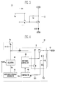
- FIG.2 is a view showing an organic light emitting display device according to an embodiment of the invention.
- FIG.3 is a view showing an example of a pixel shown in FIG.2 .
- FIG.4 is a view showing an example of a power generator shown in FIG.2 .
- FIG.5 is a waveform diagram showing an operating process of the power generator.
- FIG.6 is a view showing a simulation result of a voltage change of a first power corresponding to a change in input voltage.
- FIG.7 is a view showing an organic light emitting display device according to an embodiment of the invention.
- FIG.2 is a view showing an organic light emitting display device including a power generator according to an embodiment of the invention.
- the organic light emitting display includes: a pixel unit 20 including pixels 10 connected to scan lines (S1 to Sn) and data lines (D1 to Dm), a scan driver 30 supplying scan signals to the scan lines (S1 to Sn), a data driver 40 supplying data signals to data lines (D1 to Dm), a power generator 60 generating first power ELVDD supplied to the pixels 10, a power supply unit 70 supplying input voltage Vin to the power generator 60, and a timing controller 50 controlling the scan driver 30 and the data driver 40.
- the scan driver 30 sequentially supplies the scan signals to the scan lines (S1 to Sn).
- the pixels 10 are sequentially selected in a line unit when the scan signals are sequentially supplied to the scan lines (S1 to Sn).
- the data driver 40 supplies the data signals to the data lines (D1 to Dm) so as to be synchronized with the scan signals.
- the data signals supplied to the data lines (D1 to Dm) are supplied to the pixels 10 selected by the scan signals.
- the pixels 10 are selected when the scan signals are supplied, thereby being charged with voltage corresponding to the data signals. Further, the pixels 10 generate light having a predetermined luminance while controlling an amount of current flowing from a supplied first power ELVDD to a second power ELVSS, corresponding to the charged voltage.
- the power supply unit 70 supplies the input voltage Vin to the power generator 60.
- the power supply unit 70 may be a battery or a rectifier converting alternate current (AC) power into DC power to output the converted DC power.
- AC alternate current
- embodiments are not limited thereto, e.g., another type of power source may be used for the power supply unit 70.
- the power generator 60 is supplied with the input voltage Vin and generates the firs power ELVDD using the supplied input voltage Vin.
- the power generator 60 generates reference voltage (not shown) using the input voltage Vin or the first power ELVDD voltage according to a predetermined reference. A detailed description thereof will be provided below.
- FIG. 2 illustrates the first power ELVDD being generated in the power generator 60
- the power generator 60 may additionally generate various powers that may be used for the organic light emitting display, including the second power ELVSS.
- FIG.3 is a view showing an example of a pixel shown in FIG.2 .
- the pixel connected to an n-th scan line (Sn) and an m-th data line (Dm) will be shown for convenience of explanation.
- the pixel 10 includes an organic light emitting diode (OLED) and a pixel circuit 12 controlling an amount of current supplied to the OLED.
- OLED organic light emitting diode
- An anode electrode of the OLED is connected to the pixel circuit 12, and a cathode electrode thereof is connected to the second power ELVSS.
- the OLED as described above may generate light having a predetermined luminance, corresponding to an amount of current supplied from the pixel circuit 12.
- the pixel circuit 12 is charged with voltage corresponding to the data signal supplied from the data line (Dm) when the scan signal is supplied to the scan line (Sn). Further, an amount of current supplied to the organic light emitting diode, corresponding to the charged voltage is controlled. To this end, the pixel circuit 12 includes a first transistor T1, a second transistor T2, and a storage capacitor Cst.
- a gate electrode of the first transistor T1 is connected to the scan line Sn, and a first electrode thereof is connected to the data line Dm.
- a second electrode of the first transistor T1 is connected to one side terminal of the storage capacitor Cst.
- the first transistor T1 as described above is turned on when the scan signal is supplied to the scan line Sn, thereby supplying the data signal from the data line Dm to one side terminal of the storage capacitor Cst. At this time, the storage capacitor Cst is charged with the voltage corresponding the data signal.
- the first electrode is set to any one of a source electrode and a drain electrode, and the second electrode is set to the other of the source electrode and the drain electrode. For example, when the first electrode is set to the source electrode, the second electrode is set to the drain electrode.
- a gate electrode of the second transistor T2 is connected to one side terminal of the storage capacitor Cst, and a first electrode thereof is connected to the other side terminal of the storage capacitor Cst and the first power ELVDD. Further, a second electrode of the second transistor T2 is connected to the anode electrode of the organic light emitting diode.
- the second transistor T2 as described above controls an amount of current flowing from the supplied first power ELVDD to the a supply of the second power ELVSS via the organic light emitting diode, corresponding to the voltage stored at the storage capacitor Cst. At this time, the organic light emitting diode generates the light corresponding to an amount of current supplied from the second transistor T2.
- a structure of the pixel circuit 12 of FIG.3 described above is only an example. Therefore, embodiments are not limited thereto, e.g., the pixel circuit 12 may have a circuit structure capable of supplying the current to the organic light emitting diode and may have any one of well-known various structures.
- FIG.2 is a view showing a power generator 60 according to this embodiment.
- the power generator 60 includes a booster 61, a selector 62, a reference voltage generator 64, a switching controller 66, and a comparator 68.
- the booster 61 boosts the input voltage Vin from the power supply unit 70 according to a control of the switching controller 66 to generate the first power ELVDD.
- the booster 61 includes an inverter L1, a first switching device M1, a second switching device M2, a first resistor R1, and a second resistor R2.
- the inductor L1 is connected between the power supply unit 70 and an output terminal 67. In the inductor L1 as described above, an amount of current is controlled corresponding to a current pass controlled by the switching controller 66.
- the second switching device M2 is connected between the inductor L1 and the output terminal 67.
- the second switching device M2 as described above is turned on or turned off according to a control of the switching controller 66.
- the first switching device M1 is connected between a first node N1, which is a common terminal between the inductor L1 and the second switching device M2, and a third power supply VSS.
- the first switching device M1 as described above is turned on or turned off according to a control of the switching controller 66.
- the first switching device M1 and the second switching device M2 may be alternatively turned on and turned off. Therefore, the first switching device M1 and the second switching device M2 may have different conductivity types.
- the second switching device M2 is formed of an NMOS transistor.
- the first resistor R1 and the second resistor R2 are connected in series with each other between the output terminal 67 and the third power supply VSS.
- Feedback voltage (Vf) is applied to a second node N2, which is a common terminal between the first resistor R1 and the second resistor R2 connected in series with each other.
- the feedback voltage Vf is applied to the comparator 68.
- the third power VSS is set to voltage lower than the first power ELVDD so that the current may flow in the first node N1.
- a current measurer (not shown) may be further included between the first switching device M1 and the third power supply VSS.
- FIG.4 shows only minimum components of the booster 61 for convenience of explanation, the booster 61 may be actually configured of a circuit having known various shapes.
- the switching controller 66 controls the turning on and the turning off of the first and second switching devices M1 and M2 according to a comparison result of the comparator 68 (that is, a control signal). For example, the switching controller 66 may control a duty ratio between the first and second switching devices M1 and M2 to generate the first power ELVDD for a first power supply having a desired and/or chosen voltage.
- the selector 62 is supplied with the input voltage Vin from the power supply unit 70 and the first power ELVDD from the output voltage 67.
- the selector 62 supplied with the input voltage Vin and the first power ELVDD compares the input voltage and voltage of the first power ELVDD with each other and supplies power (the input voltage Vin or the first power ELVDD) having high voltage as output voltage Vp to the reference voltage generator 64 according to a comparison result.
- the selector 62 supplies the input voltage Vin as the output voltage Vp to the reference voltage generator 64 during an initial period (for example, at the instant when the power is to the organic light emitting display) and supplies the first power ELVDD as the output voltage Vp to the reference voltage generator 64 for a period other than the initial period.
- the reference voltage generator 64 generates reference voltage Vref using the output voltage Vp and supplies the generated reference voltage Vref to the comparator 68.
- the reference voltage Vref may be set to a predetermined voltage value.
- the reference voltage Vref is generated using the input voltage Vin in the reference voltage generator 64
- a range of the reference voltage Vref may be changed corresponding to a change in the input voltage Vin.
- the first power ELVDD may be maintained as a stable voltage value by comparing the input voltage Vin with the voltage generated in the booster 61 so as to be maintained as a constant voltage value. Accordingly, in the case in which the reference voltage Vref is generated using the first power ELVDD, the reference voltage Vref may be maintained as the constant voltage.
- the comparator 68 compares the reference voltage Vref and the feedback voltage Vf with each other and supplies a control signal to the switching controller 66 according to a comparison result. Since the reference voltage Vref is maintained as stable voltage, the comparator 68 may supply a control signal, e.g., corresponding to an exact result, to the switching controller 66 according to a change in the feedback voltage Vf. In this case, the switching controller 66 may control the turning on and the turning off of the first and second switching devices M1 and M2 so that stable voltage of the first power ELVDD may be generated according to the control signal.
- FIG.5 is a waveform diagram showing an operating process of the power generator.
- voltage of the first power ELVDD is set to the input voltage Vin of the power supply unit 70.
- the input voltage Vin is gradually increased to a preset voltage of the first voltage ELVDD by the booster 61.
- the reference voltage generator 64 generates the reference voltage Vref using the voltage at the output terminal 67.
- the reference voltage Vref may be partially changed corresponding to an increase in the voltage at the output terminal 67.
- the reference voltage Vref is not stabilized, but may be changed corresponding to the increase in the voltage at the output terminal 67 during a predetermined period ( ⁇ T). Then, the voltage at the output terminal 67, e.g., output voltage Vp, is stabilized into the voltage of the first power ELVDD, such that the reference voltage Vref may be stably maintained as a constant voltage.
- the data driver 40 supplies black data for at least one frame period, such that the pixel unit 20 displays a black image.
- the voltage at the output terminal 67 is stabilized into the voltage of the first power ELVDD during a frame period in which the black data is supplied, thereby making it possible to stably output a desired and/or chosen voltage of the first power ELVDD without deterioration in display quality.
- the at least one frame period e.g., a first and second frame period, during which the data driver 40 supplies black data valid data may be supplied to the pixel unit 20 to display a true image.
- FIG.6 is a view showing a simulation result of a voltage change of a first power corresponding to a change in input voltage.
- the voltage of the first power ELVDD is stably maintained as a constant voltage.
- the reference voltage Vref is generated using the voltage of the first power ELVDD regardless of the input voltage Vin, stabilization of the voltage may be improved.
- FIG.7 is a view showing a power generator 60' according to another embodiment of the invention.
- the power generator 60' is similar to the power generator 60 and differences therebetween are mainly described.
- the power generator 60' further includes a required voltage generator 69 installed between the selector 62 and a reference voltage generator 64'.
- the required voltage generator 69 may additionally generate a required voltage Vn using the output voltage Vp supplied from the selector 62.
- the required voltage generator 69 may additionally generate the required voltage Vn that is, e.g., required for driving the organic light emitting display device, using the voltage of the first power ELVDD supplied as the output voltage Vp.
- the generated required voltage Vn may be supplied to the reference voltage generator 64' and a separate block.
- the required voltage Vn may be generated from the stable first power ELVDD, such that it has high reliability.
- the required voltage Vn is voltage generated from the first power ELVDD and may have additional secured stability, stability and reliability of the reference voltage Vref generated in the reference voltage generator 64 may be additionally secured.
- the reference voltage is generated using the voltage of the first power.
- the first power is voltage having a change lower than a change in the input voltage. Therefore, the reference voltage generated by the first power is almost maintained as a constant voltage. Accordingly, in the case in which the booster is controlled using the reference voltage, the voltage of the first power may be maintained as a constant voltage regardless of a change in the input voltage.
Landscapes
- Engineering & Computer Science (AREA)
- Physics & Mathematics (AREA)
- Computer Hardware Design (AREA)
- General Physics & Mathematics (AREA)
- Theoretical Computer Science (AREA)
- Control Of Indicators Other Than Cathode Ray Tubes (AREA)
- Electroluminescent Light Sources (AREA)
- Control Of El Displays (AREA)
Abstract
Description
- The present invention relates to a power generator and organic light emitting display device using the same.
- Various flat panel displays having a reduced weight and volume, relative to cathode ray tube type displays have been developed. These various flat panel displays include a liquid crystal display, a field emission display, a plasma display panel, an organic light emitting display device and the like.
- Among the various flat panel displays, the organic light emitting display device (which may display an image using an organic light emitting diode generating light by recombination between an electron and a hole) has advantages in that it has a rapid response speed and is driven at low power. The organic light emitting display device includes pixels positioned at intersections between data lines and scan lines, a data driver supplying data signals to data lines, and a scan driver supplying scan signals to scan lines. The scan driver may sequentially supply the scan signals to the scan lines. The data driver may supply the data signals by the data lines so as to be synchronized with the scan signals.
- The pixels are selected when the scan signals are supplied to the scan lines, thereby receiving the data signals from the data lines. In the pixel receiving the data signal, a storage capacitor may be charged with voltage corresponding to a difference between the data signal and first power. Then, the pixel generates light having a predetermined luminance while supplying current, which corresponds to the voltage charged in the storage capacitor, from a first power supply to a second power supply via an organic light emitting diode.
- The first power supply, which is a power supply that supplies current to the pixel simultaneously with determining the voltage charged in the pixel, should maintain stable voltage regardless of an external environment. As shown in
FIG.1 apower generator 2 may generate a first power ELVDD using input voltage Vin supplied from, e.g., a battery of a mobile display apparatus. However, the input voltage Vin supplied from the battery may be changed corresponding to an external environment, e.g., at the time of a telephone call being received on the mobile display apparatus, when a portable terminal communicates with a base station, and the like. In this case, voltage of the first power ELVDD may be changed corresponding to a change in the input power Vin, such that noise such as flicker, or the like, may be generated. - The present invention sets out to provide a power generator capable of generating a stable voltage and an organic light emitting display device using the same.
- Accordingly the present invention provides a power generator including a booster boosting input voltage supplied from a power supply unit to supply the boosted input voltage to an output terminal, a selector selecting any one of the input voltage and voltage at the output terminal to supply the selected voltage as output voltage, a reference voltage generator generating reference voltage using the output voltage, a comparator comparing feedback voltage supplied from the booster and the reference voltage with each other, and a controller controls the booster so that desired voltage is output from the output terminal according to a comparison result of the comparator.
- The selector may select a higher voltage among the input voltage and the voltage at the output terminal as the output voltage. The power supply unit may be a battery. The booster may include an inductor and a second switching device connected in series with each other between the power supply unit and the output terminal, a first switching device connected between a first node, which is a common terminal between the inductor and the second switching device, and a third power supply, and a first resistor and a second resistor connected in series with each other between the output terminal and the third power supply.
- Voltage applied to the second node, which is a common terminal between the first resistor and the second resistor, may be used as the feedback voltage. The switching controller may control turn-on and turn-off of the first switching device and the second switching device so that the desired voltage is output from the output terminal. The power generator may further include a required voltage generator connected between the selector and the reference voltage generator and generating required voltage to be supplied to a separate block using the output voltage. The reference voltage generator may generate the reference voltage using the required voltage.
- The invention also provides an organic light emitting display device that includes pixels each positioned at intersection portions between scan lines and data lines and controlling an amount of current flowing from a first power supply to a second power supply via an organic light emitting diode, a power supply unit supplying input voltage, and a power generator boosting the input voltage to generate first power. The power generator includes a booster boosting the input voltage to supply the boosted input voltage to an output terminal, a selector selecting any one of the input voltage and voltage at the output terminal to supply the selected voltage as output voltage, a reference voltage generator generating reference voltage using the output voltage, a comparator comparing feedback voltage supplied from the booster and the reference voltage with each other, and a controller controls the booster so that desired voltage is output from the output terminal according to a comparison result of the comparator.
- The voltage at the output terminal may be set to the first power, and the selector may select higher voltage in the input voltage and the voltage at the output terminal as the output voltage. The organic light emitting display device may further include: a scan driver supplying scan signals to the scan lines; and a data driver supplying data signals to the data lines. The data driver may supply the data signals corresponding to black to the data lines during a period in which the voltage at the output terminal is stabilized into the voltage of the first power.
- The booster may include: an inductor and a second switching device connected in series with each other between the power supply unit and the output terminal; a first switching device connected between a first node, which is a common terminal between the inductor and the second switching device, and a third power supply VSS; and a first resistor and a second resistor connected in series with each other between the output terminal and the third power supply. Voltage applied to the second node, which is a common terminal between the first resistor and the second resistor, may be used as the feedback voltage. The switching controller may control turn-on and turn-off of the first switching device and the second switching device so that desired voltage is output from the output terminal. The power generator may further include a required voltage generator connected between the selector and the reference voltage generator and generating required voltage to be supplied to a separate block using the output voltage. The reference voltage generator may generate the reference voltage using the required voltage.
- At least some of the above and other features of the invention are set out in the claims.
- Features of the invention will become apparent to those of ordinary skill in the art upon referring to the following description of embodiments the invention, which is given with reference to the attached drawings in which:
-
FIG.1 is a view showing a voltage change of first power corresponding to a change in input voltage. -
FIG.2 is a view showing an organic light emitting display device according to an embodiment of the invention. -
FIG.3 is a view showing an example of a pixel shown inFIG.2 . -
FIG.4 is a view showing an example of a power generator shown inFIG.2 . -
FIG.5 is a waveform diagram showing an operating process of the power generator. -
FIG.6 is a view showing a simulation result of a voltage change of a first power corresponding to a change in input voltage. -
FIG.7 is a view showing an organic light emitting display device according to an embodiment of the invention. - Example embodiments of the invention will now be described more fully hereinafter with reference to the accompanying drawings; however, the invention may be embodied in different forms and should not be construed as limited to the embodiments set forth herein. Rather, these embodiments are provided so that this disclosure will be thorough and complete, and will fully convey the scope of the invention to those skilled in the art.
- The drawings and description are to be regarded as illustrative in nature and not restrictive. The dimensions of layers and regions may be exaggerated for clarity of illustration. In addition, when an element is referred to as being "on" another element, it can be directly on the other element or be indirectly on the other element with one or more intervening elements interposed therebetween. Also, when an element is referred to as being "connected to" another element, it can be directly connected to the other element or be indirectly connected to the other element with one or more intervening elements interposed therebetween. Hereinafter, like reference numerals refer to like elements.
- Hereinafter, embodiments of the invention will be described in detail with reference to
FIGS. 2 to 7 . -
FIG.2 is a view showing an organic light emitting display device including a power generator according to an embodiment of the invention. - Referring to
FIG.2 , the organic light emitting display includes: apixel unit 20 includingpixels 10 connected to scan lines (S1 to Sn) and data lines (D1 to Dm), ascan driver 30 supplying scan signals to the scan lines (S1 to Sn), adata driver 40 supplying data signals to data lines (D1 to Dm), apower generator 60 generating first power ELVDD supplied to thepixels 10, apower supply unit 70 supplying input voltage Vin to thepower generator 60, and atiming controller 50 controlling thescan driver 30 and thedata driver 40. - The
scan driver 30 sequentially supplies the scan signals to the scan lines (S1 to Sn). Thepixels 10 are sequentially selected in a line unit when the scan signals are sequentially supplied to the scan lines (S1 to Sn). - The
data driver 40 supplies the data signals to the data lines (D1 to Dm) so as to be synchronized with the scan signals. The data signals supplied to the data lines (D1 to Dm) are supplied to thepixels 10 selected by the scan signals. - The
pixels 10 are selected when the scan signals are supplied, thereby being charged with voltage corresponding to the data signals. Further, thepixels 10 generate light having a predetermined luminance while controlling an amount of current flowing from a supplied first power ELVDD to a second power ELVSS, corresponding to the charged voltage. - The
power supply unit 70 supplies the input voltage Vin to thepower generator 60. Here, thepower supply unit 70 may be a battery or a rectifier converting alternate current (AC) power into DC power to output the converted DC power. However, embodiments are not limited thereto, e.g., another type of power source may be used for thepower supply unit 70. - The
power generator 60 is supplied with the input voltage Vin and generates the firs power ELVDD using the supplied input voltage Vin. Here, thepower generator 60 generates reference voltage (not shown) using the input voltage Vin or the first power ELVDD voltage according to a predetermined reference. A detailed description thereof will be provided below. - Although
FIG. 2 illustrates the first power ELVDD being generated in thepower generator 60, embodiments are not limited thereto. For example, thepower generator 60 may additionally generate various powers that may be used for the organic light emitting display, including the second power ELVSS. -
FIG.3 is a view showing an example of a pixel shown inFIG.2 . In theFIG.3 , the pixel connected to an n-th scan line (Sn) and an m-th data line (Dm) will be shown for convenience of explanation. - Referring to
FIG.3 , thepixel 10 according to this embodiment includes an organic light emitting diode (OLED) and apixel circuit 12 controlling an amount of current supplied to the OLED. - An anode electrode of the OLED is connected to the
pixel circuit 12, and a cathode electrode thereof is connected to the second power ELVSS. The OLED as described above may generate light having a predetermined luminance, corresponding to an amount of current supplied from thepixel circuit 12. - The
pixel circuit 12 is charged with voltage corresponding to the data signal supplied from the data line (Dm) when the scan signal is supplied to the scan line (Sn). Further, an amount of current supplied to the organic light emitting diode, corresponding to the charged voltage is controlled. To this end, thepixel circuit 12 includes a first transistor T1, a second transistor T2, and a storage capacitor Cst. - A gate electrode of the first transistor T1 is connected to the scan line Sn, and a first electrode thereof is connected to the data line Dm. In addition, a second electrode of the first transistor T1 is connected to one side terminal of the storage capacitor Cst. The first transistor T1 as described above is turned on when the scan signal is supplied to the scan line Sn, thereby supplying the data signal from the data line Dm to one side terminal of the storage capacitor Cst. At this time, the storage capacitor Cst is charged with the voltage corresponding the data signal. The first electrode is set to any one of a source electrode and a drain electrode, and the second electrode is set to the other of the source electrode and the drain electrode. For example, when the first electrode is set to the source electrode, the second electrode is set to the drain electrode.
- A gate electrode of the second transistor T2 is connected to one side terminal of the storage capacitor Cst, and a first electrode thereof is connected to the other side terminal of the storage capacitor Cst and the first power ELVDD. Further, a second electrode of the second transistor T2 is connected to the anode electrode of the organic light emitting diode. The second transistor T2 as described above controls an amount of current flowing from the supplied first power ELVDD to the a supply of the second power ELVSS via the organic light emitting diode, corresponding to the voltage stored at the storage capacitor Cst. At this time, the organic light emitting diode generates the light corresponding to an amount of current supplied from the second transistor T2.
- A structure of the
pixel circuit 12 ofFIG.3 described above is only an example. Therefore, embodiments are not limited thereto, e.g., thepixel circuit 12 may have a circuit structure capable of supplying the current to the organic light emitting diode and may have any one of well-known various structures. -
FIG.2 is a view showing apower generator 60 according to this embodiment. Referring toFIG.4 , thepower generator 60 includes abooster 61, aselector 62, areference voltage generator 64, a switchingcontroller 66, and acomparator 68. - The
booster 61 boosts the input voltage Vin from thepower supply unit 70 according to a control of the switchingcontroller 66 to generate the first power ELVDD. To this end, thebooster 61 includes an inverter L1, a first switching device M1, a second switching device M2, a first resistor R1, and a second resistor R2. - The inductor L1 is connected between the
power supply unit 70 and anoutput terminal 67. In the inductor L1 as described above, an amount of current is controlled corresponding to a current pass controlled by the switchingcontroller 66. - The second switching device M2 is connected between the inductor L1 and the
output terminal 67. The second switching device M2 as described above is turned on or turned off according to a control of the switchingcontroller 66. - The first switching device M1 is connected between a first node N1, which is a common terminal between the inductor L1 and the second switching device M2, and a third power supply VSS. The first switching device M1 as described above is turned on or turned off according to a control of the switching
controller 66. For example, the first switching device M1 and the second switching device M2 may be alternatively turned on and turned off. Therefore, the first switching device M1 and the second switching device M2 may have different conductivity types. As an example, in the case in which the first switching device M1 is formed of a PMOS transistor, the second switching device M2 is formed of an NMOS transistor. - The first resistor R1 and the second resistor R2 are connected in series with each other between the
output terminal 67 and the third power supply VSS. Feedback voltage (Vf) is applied to a second node N2, which is a common terminal between the first resistor R1 and the second resistor R2 connected in series with each other. The feedback voltage Vf is applied to thecomparator 68. - The third power VSS is set to voltage lower than the first power ELVDD so that the current may flow in the first node N1. In addition, a current measurer (not shown) may be further included between the first switching device M1 and the third power supply VSS. Although
FIG.4 shows only minimum components of thebooster 61 for convenience of explanation, thebooster 61 may be actually configured of a circuit having known various shapes. - The switching
controller 66 controls the turning on and the turning off of the first and second switching devices M1 and M2 according to a comparison result of the comparator 68 (that is, a control signal). For example, the switchingcontroller 66 may control a duty ratio between the first and second switching devices M1 and M2 to generate the first power ELVDD for a first power supply having a desired and/or chosen voltage. - The
selector 62 is supplied with the input voltage Vin from thepower supply unit 70 and the first power ELVDD from theoutput voltage 67. Theselector 62 supplied with the input voltage Vin and the first power ELVDD compares the input voltage and voltage of the first power ELVDD with each other and supplies power (the input voltage Vin or the first power ELVDD) having high voltage as output voltage Vp to thereference voltage generator 64 according to a comparison result. - In this case, the
selector 62 supplies the input voltage Vin as the output voltage Vp to thereference voltage generator 64 during an initial period (for example, at the instant when the power is to the organic light emitting display) and supplies the first power ELVDD as the output voltage Vp to thereference voltage generator 64 for a period other than the initial period. - The
reference voltage generator 64 generates reference voltage Vref using the output voltage Vp and supplies the generated reference voltage Vref to thecomparator 68. The reference voltage Vref may be set to a predetermined voltage value. - In the case in which the reference voltage Vref is generated using the input voltage Vin in the
reference voltage generator 64, a range of the reference voltage Vref may be changed corresponding to a change in the input voltage Vin. On the other hand, the first power ELVDD may be maintained as a stable voltage value by comparing the input voltage Vin with the voltage generated in thebooster 61 so as to be maintained as a constant voltage value. Accordingly, in the case in which the reference voltage Vref is generated using the first power ELVDD, the reference voltage Vref may be maintained as the constant voltage. - The
comparator 68 compares the reference voltage Vref and the feedback voltage Vf with each other and supplies a control signal to the switchingcontroller 66 according to a comparison result. Since the reference voltage Vref is maintained as stable voltage, thecomparator 68 may supply a control signal, e.g., corresponding to an exact result, to the switchingcontroller 66 according to a change in the feedback voltage Vf. In this case, the switchingcontroller 66 may control the turning on and the turning off of the first and second switching devices M1 and M2 so that stable voltage of the first power ELVDD may be generated according to the control signal. -
FIG.5 is a waveform diagram showing an operating process of the power generator. - Referring to
FIG.5 , when the power is supplied, voltage of the first power ELVDD is set to the input voltage Vin of thepower supply unit 70. In addition, the input voltage Vin is gradually increased to a preset voltage of the first voltage ELVDD by thebooster 61. Here, in the case in which voltage at theoutput terminal 67 exceeds the input voltage Vin, thereference voltage generator 64 generates the reference voltage Vref using the voltage at theoutput terminal 67. - In this case, the reference voltage Vref may be partially changed corresponding to an increase in the voltage at the
output terminal 67. As an example, the reference voltage Vref is not stabilized, but may be changed corresponding to the increase in the voltage at theoutput terminal 67 during a predetermined period (ΔT). Then, the voltage at theoutput terminal 67, e.g., output voltage Vp, is stabilized into the voltage of the first power ELVDD, such that the reference voltage Vref may be stably maintained as a constant voltage. - When power is supplied to the organic light emitting display device, the
data driver 40 supplies black data for at least one frame period, such that thepixel unit 20 displays a black image. The voltage at theoutput terminal 67 is stabilized into the voltage of the first power ELVDD during a frame period in which the black data is supplied, thereby making it possible to stably output a desired and/or chosen voltage of the first power ELVDD without deterioration in display quality. After the at least one frame period, e.g., a first and second frame period, during which thedata driver 40 supplies black data valid data may be supplied to thepixel unit 20 to display a true image. -
FIG.6 is a view showing a simulation result of a voltage change of a first power corresponding to a change in input voltage. - Referring to
FIG.6 , although the input voltage Vin is increased or decreased by a 500mV unit, the voltage of the first power ELVDD is stably maintained as a constant voltage. In other words, since the reference voltage Vref is generated using the voltage of the first power ELVDD regardless of the input voltage Vin, stabilization of the voltage may be improved. -
FIG.7 is a view showing a power generator 60' according to another embodiment of the invention. The power generator 60' is similar to thepower generator 60 and differences therebetween are mainly described. - Referring to
FIG.7 , the power generator 60' according to this further embodiment further includes a requiredvoltage generator 69 installed between theselector 62 and a reference voltage generator 64'. - The required
voltage generator 69 may additionally generate a required voltage Vn using the output voltage Vp supplied from theselector 62. The requiredvoltage generator 69 may additionally generate the required voltage Vn that is, e.g., required for driving the organic light emitting display device, using the voltage of the first power ELVDD supplied as the output voltage Vp. The generated required voltage Vn may be supplied to the reference voltage generator 64' and a separate block. - The required voltage Vn may be generated from the stable first power ELVDD, such that it has high reliability. In addition, since the required voltage Vn is voltage generated from the first power ELVDD and may have additional secured stability, stability and reliability of the reference voltage Vref generated in the
reference voltage generator 64 may be additionally secured. - As set forth above, with the power generator and the organic light emitting display device using the same according to the invention, in the case in which the voltage of the first power exceeds the input voltage of the battery, the reference voltage is generated using the voltage of the first power. Here, the first power is voltage having a change lower than a change in the input voltage. Therefore, the reference voltage generated by the first power is almost maintained as a constant voltage. Accordingly, in the case in which the booster is controlled using the reference voltage, the voltage of the first power may be maintained as a constant voltage regardless of a change in the input voltage.
- Embodiments of the invention have been disclosed herein, and although specific terms are employed, they are used and are to be interpreted in a generic and descriptive sense only and not for purpose of limitation. Accordingly, it will be understood by those of ordinary skill in the art that various changes in form and details may be made without departing from the scope of the present invention as set forth in the following claims.
Claims (11)
- A power generator, comprising:a booster adapted to boost an input voltage supplied from a power supply unit and supply a boosted input voltage to an output terminal;a selector adapted to select one of the input voltage and a voltage at the output terminal as a selected voltage and supply the selected voltage as an output voltage;a reference voltage generator adapted to generate a reference voltage based on the output voltage;a comparator adapted to compare a feedback voltage supplied from the booster and the reference voltage with each other; anda controller adapted to control the booster to output a chosen voltage from the output terminal according to a comparison result of the comparator.
- A power generator according to claim 1, wherein the selector is adapted to select as the output voltage a higher voltage among the input voltage and the voltage at the output terminal.
- A power generator according to claim 1 or 2, wherein the power supply unit is a battery.
- A power generator according to any preceding claim, wherein the booster includes:an inductor and a second switching device connected in series with each other between the power supply unit and the output terminal,a first switching device connected between a first node and a third power supply, the first node being a common terminal between the inductor and the second switching device, anda first resistor and a second resistor connected in series with each other between the output terminal and the third power supply.
- A power generator according to claim 4, adapted to apply a voltage to the second node that corresponds to the feedback voltage, the second node being a common terminal between the first resistor and the second resistor.
- A power generator according to claim 4 or 5, further comprising a switching controller that controls turned-on states and turned-off states of the first and second switching devices such that the chosen voltage is output from the output terminal.
- A power generator according to any preceding claim, further comprising a required voltage generator connected between the selector and the reference voltage generator, the required voltage generator being adapted to generate a required voltage to be supplied to a separate block using the output voltage.
- A power generator according to claim 7, wherein the reference voltage generator is adapted to generate the reference voltage using the required voltage.
- An organic light emitting display device, comprising:pixels positioned at intersection portions between scan lines and data lines, the pixels being adapted to control an amount of current flowing from a first power supply to a second power supply via an organic light emitting diode;a power supply unit adapted to supply an input voltage; and
a power generator adapted to boost the input voltage to generate a first power, the said power generator being as set out in one of Claims 1 to 8. - An organic light emitting display device according to claim 9, further comprising:a scan driver adapted to supply scan signals to the scan lines; anda data driver adapted to supply data signals to the data lines.
- An organic light emitting display device according to claim 11, wherein the data driver is adapted to supply to the data lines data signals corresponding to black, during a period in which the voltage at the output terminal is stabilized into the voltage of the first power.
Applications Claiming Priority (1)
| Application Number | Priority Date | Filing Date | Title |
|---|---|---|---|
| KR1020120022336A KR101965892B1 (en) | 2012-03-05 | 2012-03-05 | DC-DC Converter and Organic Light Emitting Display Device Using the same |
Publications (2)
| Publication Number | Publication Date |
|---|---|
| EP2637161A2 true EP2637161A2 (en) | 2013-09-11 |
| EP2637161A3 EP2637161A3 (en) | 2014-02-26 |
Family
ID=47143033
Family Applications (1)
| Application Number | Title | Priority Date | Filing Date |
|---|---|---|---|
| EP20120191938 Withdrawn EP2637161A3 (en) | 2012-03-05 | 2012-11-09 | Power generator and organic light emitting display device using the same |
Country Status (4)
| Country | Link |
|---|---|
| US (1) | US9123286B2 (en) |
| EP (1) | EP2637161A3 (en) |
| KR (1) | KR101965892B1 (en) |
| TW (1) | TWI581236B (en) |
Families Citing this family (489)
| Publication number | Priority date | Publication date | Assignee | Title |
|---|---|---|---|---|
| US9060770B2 (en) | 2003-05-20 | 2015-06-23 | Ethicon Endo-Surgery, Inc. | Robotically-driven surgical instrument with E-beam driver |
| US20070084897A1 (en) | 2003-05-20 | 2007-04-19 | Shelton Frederick E Iv | Articulating surgical stapling instrument incorporating a two-piece e-beam firing mechanism |
| US9072535B2 (en) | 2011-05-27 | 2015-07-07 | Ethicon Endo-Surgery, Inc. | Surgical stapling instruments with rotatable staple deployment arrangements |
| US11890012B2 (en) | 2004-07-28 | 2024-02-06 | Cilag Gmbh International | Staple cartridge comprising cartridge body and attached support |
| US11998198B2 (en) | 2004-07-28 | 2024-06-04 | Cilag Gmbh International | Surgical stapling instrument incorporating a two-piece E-beam firing mechanism |
| US8215531B2 (en) | 2004-07-28 | 2012-07-10 | Ethicon Endo-Surgery, Inc. | Surgical stapling instrument having a medical substance dispenser |
| US7673781B2 (en) | 2005-08-31 | 2010-03-09 | Ethicon Endo-Surgery, Inc. | Surgical stapling device with staple driver that supports multiple wire diameter staples |
| US11484312B2 (en) | 2005-08-31 | 2022-11-01 | Cilag Gmbh International | Staple cartridge comprising a staple driver arrangement |
| US9237891B2 (en) | 2005-08-31 | 2016-01-19 | Ethicon Endo-Surgery, Inc. | Robotically-controlled surgical stapling devices that produce formed staples having different lengths |
| US7934630B2 (en) | 2005-08-31 | 2011-05-03 | Ethicon Endo-Surgery, Inc. | Staple cartridges for forming staples having differing formed staple heights |
| US11246590B2 (en) | 2005-08-31 | 2022-02-15 | Cilag Gmbh International | Staple cartridge including staple drivers having different unfired heights |
| US7669746B2 (en) | 2005-08-31 | 2010-03-02 | Ethicon Endo-Surgery, Inc. | Staple cartridges for forming staples having differing formed staple heights |
| US10159482B2 (en) | 2005-08-31 | 2018-12-25 | Ethicon Llc | Fastener cartridge assembly comprising a fixed anvil and different staple heights |
| US20070106317A1 (en) | 2005-11-09 | 2007-05-10 | Shelton Frederick E Iv | Hydraulically and electrically actuated articulation joints for surgical instruments |
| US20110006101A1 (en) | 2009-02-06 | 2011-01-13 | EthiconEndo-Surgery, Inc. | Motor driven surgical fastener device with cutting member lockout arrangements |
| US8186555B2 (en) | 2006-01-31 | 2012-05-29 | Ethicon Endo-Surgery, Inc. | Motor-driven surgical cutting and fastening instrument with mechanical closure system |
| US20120292367A1 (en) | 2006-01-31 | 2012-11-22 | Ethicon Endo-Surgery, Inc. | Robotically-controlled end effector |
| US7753904B2 (en) | 2006-01-31 | 2010-07-13 | Ethicon Endo-Surgery, Inc. | Endoscopic surgical instrument with a handle that can articulate with respect to the shaft |
| US11278279B2 (en) | 2006-01-31 | 2022-03-22 | Cilag Gmbh International | Surgical instrument assembly |
| US20110024477A1 (en) | 2009-02-06 | 2011-02-03 | Hall Steven G | Driven Surgical Stapler Improvements |
| US11793518B2 (en) | 2006-01-31 | 2023-10-24 | Cilag Gmbh International | Powered surgical instruments with firing system lockout arrangements |
| US8820603B2 (en) | 2006-01-31 | 2014-09-02 | Ethicon Endo-Surgery, Inc. | Accessing data stored in a memory of a surgical instrument |
| US7845537B2 (en) | 2006-01-31 | 2010-12-07 | Ethicon Endo-Surgery, Inc. | Surgical instrument having recording capabilities |
| US11224427B2 (en) | 2006-01-31 | 2022-01-18 | Cilag Gmbh International | Surgical stapling system including a console and retraction assembly |
| US8708213B2 (en) | 2006-01-31 | 2014-04-29 | Ethicon Endo-Surgery, Inc. | Surgical instrument having a feedback system |
| US20110290856A1 (en) | 2006-01-31 | 2011-12-01 | Ethicon Endo-Surgery, Inc. | Robotically-controlled surgical instrument with force-feedback capabilities |
| US9861359B2 (en) | 2006-01-31 | 2018-01-09 | Ethicon Llc | Powered surgical instruments with firing system lockout arrangements |
| US8992422B2 (en) | 2006-03-23 | 2015-03-31 | Ethicon Endo-Surgery, Inc. | Robotically-controlled endoscopic accessory channel |
| US20070225562A1 (en) | 2006-03-23 | 2007-09-27 | Ethicon Endo-Surgery, Inc. | Articulating endoscopic accessory channel |
| US8322455B2 (en) | 2006-06-27 | 2012-12-04 | Ethicon Endo-Surgery, Inc. | Manually driven surgical cutting and fastening instrument |
| US10568652B2 (en) | 2006-09-29 | 2020-02-25 | Ethicon Llc | Surgical staples having attached drivers of different heights and stapling instruments for deploying the same |
| US8485412B2 (en) | 2006-09-29 | 2013-07-16 | Ethicon Endo-Surgery, Inc. | Surgical staples having attached drivers and stapling instruments for deploying the same |
| US11980366B2 (en) | 2006-10-03 | 2024-05-14 | Cilag Gmbh International | Surgical instrument |
| US8632535B2 (en) | 2007-01-10 | 2014-01-21 | Ethicon Endo-Surgery, Inc. | Interlock and surgical instrument including same |
| US8652120B2 (en) | 2007-01-10 | 2014-02-18 | Ethicon Endo-Surgery, Inc. | Surgical instrument with wireless communication between control unit and sensor transponders |
| US8684253B2 (en) | 2007-01-10 | 2014-04-01 | Ethicon Endo-Surgery, Inc. | Surgical instrument with wireless communication between a control unit of a robotic system and remote sensor |
| US11291441B2 (en) | 2007-01-10 | 2022-04-05 | Cilag Gmbh International | Surgical instrument with wireless communication between control unit and remote sensor |
| US20080169332A1 (en) | 2007-01-11 | 2008-07-17 | Shelton Frederick E | Surgical stapling device with a curved cutting member |
| US11039836B2 (en) | 2007-01-11 | 2021-06-22 | Cilag Gmbh International | Staple cartridge for use with a surgical stapling instrument |
| US8727197B2 (en) | 2007-03-15 | 2014-05-20 | Ethicon Endo-Surgery, Inc. | Staple cartridge cavity configuration with cooperative surgical staple |
| US8893946B2 (en) | 2007-03-28 | 2014-11-25 | Ethicon Endo-Surgery, Inc. | Laparoscopic tissue thickness and clamp load measuring devices |
| US8931682B2 (en) | 2007-06-04 | 2015-01-13 | Ethicon Endo-Surgery, Inc. | Robotically-controlled shaft based rotary drive systems for surgical instruments |
| US11857181B2 (en) | 2007-06-04 | 2024-01-02 | Cilag Gmbh International | Robotically-controlled shaft based rotary drive systems for surgical instruments |
| US8308040B2 (en) | 2007-06-22 | 2012-11-13 | Ethicon Endo-Surgery, Inc. | Surgical stapling instrument with an articulatable end effector |
| US7753245B2 (en) | 2007-06-22 | 2010-07-13 | Ethicon Endo-Surgery, Inc. | Surgical stapling instruments |
| US11849941B2 (en) | 2007-06-29 | 2023-12-26 | Cilag Gmbh International | Staple cartridge having staple cavities extending at a transverse angle relative to a longitudinal cartridge axis |
| US11986183B2 (en) | 2008-02-14 | 2024-05-21 | Cilag Gmbh International | Surgical cutting and fastening instrument comprising a plurality of sensors to measure an electrical parameter |
| US9179912B2 (en) | 2008-02-14 | 2015-11-10 | Ethicon Endo-Surgery, Inc. | Robotically-controlled motorized surgical cutting and fastening instrument |
| US7866527B2 (en) | 2008-02-14 | 2011-01-11 | Ethicon Endo-Surgery, Inc. | Surgical stapling apparatus with interlockable firing system |
| US7819298B2 (en) | 2008-02-14 | 2010-10-26 | Ethicon Endo-Surgery, Inc. | Surgical stapling apparatus with control features operable with one hand |
| RU2493788C2 (en) | 2008-02-14 | 2013-09-27 | Этикон Эндо-Серджери, Инк. | Surgical cutting and fixing instrument, which has radio-frequency electrodes |
| US8573465B2 (en) | 2008-02-14 | 2013-11-05 | Ethicon Endo-Surgery, Inc. | Robotically-controlled surgical end effector system with rotary actuated closure systems |
| US8636736B2 (en) | 2008-02-14 | 2014-01-28 | Ethicon Endo-Surgery, Inc. | Motorized surgical cutting and fastening instrument |
| US8758391B2 (en) | 2008-02-14 | 2014-06-24 | Ethicon Endo-Surgery, Inc. | Interchangeable tools for surgical instruments |
| US8657174B2 (en) | 2008-02-14 | 2014-02-25 | Ethicon Endo-Surgery, Inc. | Motorized surgical cutting and fastening instrument having handle based power source |
| US11272927B2 (en) | 2008-02-15 | 2022-03-15 | Cilag Gmbh International | Layer arrangements for surgical staple cartridges |
| US20130153641A1 (en) | 2008-02-15 | 2013-06-20 | Ethicon Endo-Surgery, Inc. | Releasable layer of material and surgical end effector having the same |
| US9386983B2 (en) | 2008-09-23 | 2016-07-12 | Ethicon Endo-Surgery, Llc | Robotically-controlled motorized surgical instrument |
| US8210411B2 (en) | 2008-09-23 | 2012-07-03 | Ethicon Endo-Surgery, Inc. | Motor-driven surgical cutting instrument |
| US9005230B2 (en) | 2008-09-23 | 2015-04-14 | Ethicon Endo-Surgery, Inc. | Motorized surgical instrument |
| US11648005B2 (en) | 2008-09-23 | 2023-05-16 | Cilag Gmbh International | Robotically-controlled motorized surgical instrument with an end effector |
| US8608045B2 (en) | 2008-10-10 | 2013-12-17 | Ethicon Endo-Sugery, Inc. | Powered surgical cutting and stapling apparatus with manually retractable firing system |
| US8517239B2 (en) | 2009-02-05 | 2013-08-27 | Ethicon Endo-Surgery, Inc. | Surgical stapling instrument comprising a magnetic element driver |
| US8444036B2 (en) | 2009-02-06 | 2013-05-21 | Ethicon Endo-Surgery, Inc. | Motor driven surgical fastener device with mechanisms for adjusting a tissue gap within the end effector |
| JP2012517287A (en) | 2009-02-06 | 2012-08-02 | エシコン・エンド−サージェリィ・インコーポレイテッド | Improvement of driven surgical stapler |
| US8220688B2 (en) | 2009-12-24 | 2012-07-17 | Ethicon Endo-Surgery, Inc. | Motor-driven surgical cutting instrument with electric actuator directional control assembly |
| US8851354B2 (en) | 2009-12-24 | 2014-10-07 | Ethicon Endo-Surgery, Inc. | Surgical cutting instrument that analyzes tissue thickness |
| US8783543B2 (en) | 2010-07-30 | 2014-07-22 | Ethicon Endo-Surgery, Inc. | Tissue acquisition arrangements and methods for surgical stapling devices |
| US10405854B2 (en) | 2010-09-30 | 2019-09-10 | Ethicon Llc | Surgical stapling cartridge with layer retention features |
| US9320523B2 (en) | 2012-03-28 | 2016-04-26 | Ethicon Endo-Surgery, Llc | Tissue thickness compensator comprising tissue ingrowth features |
| US9113865B2 (en) | 2010-09-30 | 2015-08-25 | Ethicon Endo-Surgery, Inc. | Staple cartridge comprising a layer |
| US9220501B2 (en) | 2010-09-30 | 2015-12-29 | Ethicon Endo-Surgery, Inc. | Tissue thickness compensators |
| US10945731B2 (en) | 2010-09-30 | 2021-03-16 | Ethicon Llc | Tissue thickness compensator comprising controlled release and expansion |
| US9301753B2 (en) | 2010-09-30 | 2016-04-05 | Ethicon Endo-Surgery, Llc | Expandable tissue thickness compensator |
| US12213666B2 (en) | 2010-09-30 | 2025-02-04 | Cilag Gmbh International | Tissue thickness compensator comprising layers |
| US9055941B2 (en) | 2011-09-23 | 2015-06-16 | Ethicon Endo-Surgery, Inc. | Staple cartridge including collapsible deck |
| US9314246B2 (en) | 2010-09-30 | 2016-04-19 | Ethicon Endo-Surgery, Llc | Tissue stapler having a thickness compensator incorporating an anti-inflammatory agent |
| US9241714B2 (en) | 2011-04-29 | 2016-01-26 | Ethicon Endo-Surgery, Inc. | Tissue thickness compensator and method for making the same |
| US9364233B2 (en) | 2010-09-30 | 2016-06-14 | Ethicon Endo-Surgery, Llc | Tissue thickness compensators for circular surgical staplers |
| US9332974B2 (en) | 2010-09-30 | 2016-05-10 | Ethicon Endo-Surgery, Llc | Layered tissue thickness compensator |
| US11812965B2 (en) | 2010-09-30 | 2023-11-14 | Cilag Gmbh International | Layer of material for a surgical end effector |
| US11298125B2 (en) | 2010-09-30 | 2022-04-12 | Cilag Gmbh International | Tissue stapler having a thickness compensator |
| US11925354B2 (en) | 2010-09-30 | 2024-03-12 | Cilag Gmbh International | Staple cartridge comprising staples positioned within a compressible portion thereof |
| AU2011308701B2 (en) | 2010-09-30 | 2013-11-14 | Ethicon Endo-Surgery, Inc. | Fastener system comprising a retention matrix and an alignment matrix |
| US9307989B2 (en) | 2012-03-28 | 2016-04-12 | Ethicon Endo-Surgery, Llc | Tissue stapler having a thickness compensator incorportating a hydrophobic agent |
| US9220500B2 (en) | 2010-09-30 | 2015-12-29 | Ethicon Endo-Surgery, Inc. | Tissue thickness compensator comprising structure to produce a resilient load |
| US9232941B2 (en) | 2010-09-30 | 2016-01-12 | Ethicon Endo-Surgery, Inc. | Tissue thickness compensator comprising a reservoir |
| US9629814B2 (en) | 2010-09-30 | 2017-04-25 | Ethicon Endo-Surgery, Llc | Tissue thickness compensator configured to redistribute compressive forces |
| US8695866B2 (en) | 2010-10-01 | 2014-04-15 | Ethicon Endo-Surgery, Inc. | Surgical instrument having a power control circuit |
| BR112013027794B1 (en) | 2011-04-29 | 2020-12-15 | Ethicon Endo-Surgery, Inc | CLAMP CARTRIDGE SET |
| US11207064B2 (en) | 2011-05-27 | 2021-12-28 | Cilag Gmbh International | Automated end effector component reloading system for use with a robotic system |
| US9050084B2 (en) | 2011-09-23 | 2015-06-09 | Ethicon Endo-Surgery, Inc. | Staple cartridge including collapsible deck arrangement |
| US9044230B2 (en) | 2012-02-13 | 2015-06-02 | Ethicon Endo-Surgery, Inc. | Surgical cutting and fastening instrument with apparatus for determining cartridge and firing motion status |
| CN104379068B (en) | 2012-03-28 | 2017-09-22 | 伊西康内外科公司 | Holding device assembly including tissue thickness compensation part |
| MX350846B (en) | 2012-03-28 | 2017-09-22 | Ethicon Endo Surgery Inc | Tissue thickness compensator comprising capsules defining a low pressure environment. |
| MX358135B (en) | 2012-03-28 | 2018-08-06 | Ethicon Endo Surgery Inc | Tissue thickness compensator comprising a plurality of layers. |
| US9101358B2 (en) | 2012-06-15 | 2015-08-11 | Ethicon Endo-Surgery, Inc. | Articulatable surgical instrument comprising a firing drive |
| US12383267B2 (en) | 2012-06-28 | 2025-08-12 | Cilag Gmbh International | Robotically powered surgical device with manually-actuatable reversing system |
| US9204879B2 (en) | 2012-06-28 | 2015-12-08 | Ethicon Endo-Surgery, Inc. | Flexible drive member |
| US9282974B2 (en) | 2012-06-28 | 2016-03-15 | Ethicon Endo-Surgery, Llc | Empty clip cartridge lockout |
| BR112014032776B1 (en) | 2012-06-28 | 2021-09-08 | Ethicon Endo-Surgery, Inc | SURGICAL INSTRUMENT SYSTEM AND SURGICAL KIT FOR USE WITH A SURGICAL INSTRUMENT SYSTEM |
| US20140001231A1 (en) | 2012-06-28 | 2014-01-02 | Ethicon Endo-Surgery, Inc. | Firing system lockout arrangements for surgical instruments |
| US11197671B2 (en) | 2012-06-28 | 2021-12-14 | Cilag Gmbh International | Stapling assembly comprising a lockout |
| US9289256B2 (en) | 2012-06-28 | 2016-03-22 | Ethicon Endo-Surgery, Llc | Surgical end effectors having angled tissue-contacting surfaces |
| US9226751B2 (en) | 2012-06-28 | 2016-01-05 | Ethicon Endo-Surgery, Inc. | Surgical instrument system including replaceable end effectors |
| JP6290201B2 (en) | 2012-06-28 | 2018-03-07 | エシコン・エンド−サージェリィ・インコーポレイテッドEthicon Endo−Surgery,Inc. | Lockout for empty clip cartridge |
| JP6104532B2 (en) * | 2012-07-23 | 2017-03-29 | ラピスセミコンダクタ株式会社 | Semiconductor device, drive mechanism, and motor drive control method |
| MX368026B (en) | 2013-03-01 | 2019-09-12 | Ethicon Endo Surgery Inc | Articulatable surgical instruments with conductive pathways for signal communication. |
| US9307986B2 (en) | 2013-03-01 | 2016-04-12 | Ethicon Endo-Surgery, Llc | Surgical instrument soft stop |
| RU2669463C2 (en) | 2013-03-01 | 2018-10-11 | Этикон Эндо-Серджери, Инк. | Surgical instrument with soft stop |
| US9345481B2 (en) | 2013-03-13 | 2016-05-24 | Ethicon Endo-Surgery, Llc | Staple cartridge tissue thickness sensor system |
| US9351726B2 (en) | 2013-03-14 | 2016-05-31 | Ethicon Endo-Surgery, Llc | Articulation control system for articulatable surgical instruments |
| US9629629B2 (en) | 2013-03-14 | 2017-04-25 | Ethicon Endo-Surgey, LLC | Control systems for surgical instruments |
| US9795384B2 (en) | 2013-03-27 | 2017-10-24 | Ethicon Llc | Fastener cartridge comprising a tissue thickness compensator and a gap setting element |
| US9572577B2 (en) | 2013-03-27 | 2017-02-21 | Ethicon Endo-Surgery, Llc | Fastener cartridge comprising a tissue thickness compensator including openings therein |
| US9332984B2 (en) | 2013-03-27 | 2016-05-10 | Ethicon Endo-Surgery, Llc | Fastener cartridge assemblies |
| BR112015026109B1 (en) | 2013-04-16 | 2022-02-22 | Ethicon Endo-Surgery, Inc | surgical instrument |
| US9801626B2 (en) | 2013-04-16 | 2017-10-31 | Ethicon Llc | Modular motor driven surgical instruments with alignment features for aligning rotary drive shafts with surgical end effector shafts |
| US9574644B2 (en) | 2013-05-30 | 2017-02-21 | Ethicon Endo-Surgery, Llc | Power module for use with a surgical instrument |
| US20150053737A1 (en) | 2013-08-23 | 2015-02-26 | Ethicon Endo-Surgery, Inc. | End effector detection systems for surgical instruments |
| MX369362B (en) | 2013-08-23 | 2019-11-06 | Ethicon Endo Surgery Llc | Firing member retraction devices for powered surgical instruments. |
| KR102123589B1 (en) * | 2013-11-27 | 2020-06-17 | 삼성디스플레이 주식회사 | Organic light emitting display device |
| US20150173756A1 (en) | 2013-12-23 | 2015-06-25 | Ethicon Endo-Surgery, Inc. | Surgical cutting and stapling methods |
| US9687232B2 (en) | 2013-12-23 | 2017-06-27 | Ethicon Llc | Surgical staples |
| US9839428B2 (en) | 2013-12-23 | 2017-12-12 | Ethicon Llc | Surgical cutting and stapling instruments with independent jaw control features |
| US9724092B2 (en) | 2013-12-23 | 2017-08-08 | Ethicon Llc | Modular surgical instruments |
| KR102203522B1 (en) * | 2014-01-03 | 2021-01-15 | 삼성디스플레이 주식회사 | Driving voltage generating device, display device including the same and driving voltage generating method |
| US9962161B2 (en) | 2014-02-12 | 2018-05-08 | Ethicon Llc | Deliverable surgical instrument |
| BR112016019387B1 (en) | 2014-02-24 | 2022-11-29 | Ethicon Endo-Surgery, Llc | SURGICAL INSTRUMENT SYSTEM AND FASTENER CARTRIDGE FOR USE WITH A SURGICAL FIXING INSTRUMENT |
| US9757124B2 (en) | 2014-02-24 | 2017-09-12 | Ethicon Llc | Implantable layer assemblies |
| US20150272557A1 (en) | 2014-03-26 | 2015-10-01 | Ethicon Endo-Surgery, Inc. | Modular surgical instrument system |
| US9913642B2 (en) | 2014-03-26 | 2018-03-13 | Ethicon Llc | Surgical instrument comprising a sensor system |
| US10013049B2 (en) | 2014-03-26 | 2018-07-03 | Ethicon Llc | Power management through sleep options of segmented circuit and wake up control |
| US9750499B2 (en) | 2014-03-26 | 2017-09-05 | Ethicon Llc | Surgical stapling instrument system |
| US12232723B2 (en) | 2014-03-26 | 2025-02-25 | Cilag Gmbh International | Systems and methods for controlling a segmented circuit |
| BR112016021943B1 (en) | 2014-03-26 | 2022-06-14 | Ethicon Endo-Surgery, Llc | SURGICAL INSTRUMENT FOR USE BY AN OPERATOR IN A SURGICAL PROCEDURE |
| CN106456176B (en) | 2014-04-16 | 2019-06-28 | 伊西康内外科有限责任公司 | Fastener Cartridge Including Extensions With Different Configurations |
| JP6532889B2 (en) | 2014-04-16 | 2019-06-19 | エシコン エルエルシーEthicon LLC | Fastener cartridge assembly and staple holder cover arrangement |
| US20150297223A1 (en) | 2014-04-16 | 2015-10-22 | Ethicon Endo-Surgery, Inc. | Fastener cartridges including extensions having different configurations |
| US10327764B2 (en) | 2014-09-26 | 2019-06-25 | Ethicon Llc | Method for creating a flexible staple line |
| CN106456158B (en) | 2014-04-16 | 2019-02-05 | 伊西康内外科有限责任公司 | Fastener magazines including non-conforming fasteners |
| US10561422B2 (en) | 2014-04-16 | 2020-02-18 | Ethicon Llc | Fastener cartridge comprising deployable tissue engaging members |
| US10045781B2 (en) | 2014-06-13 | 2018-08-14 | Ethicon Llc | Closure lockout systems for surgical instruments |
| KR102241848B1 (en) * | 2014-08-12 | 2021-04-20 | 삼성디스플레이 주식회사 | Power supply device and Organic light emitting display apparatus comprising the power supply device |
| US9724094B2 (en) | 2014-09-05 | 2017-08-08 | Ethicon Llc | Adjunct with integrated sensors to quantify tissue compression |
| BR112017004361B1 (en) | 2014-09-05 | 2023-04-11 | Ethicon Llc | ELECTRONIC SYSTEM FOR A SURGICAL INSTRUMENT |
| US11311294B2 (en) | 2014-09-05 | 2022-04-26 | Cilag Gmbh International | Powered medical device including measurement of closure state of jaws |
| US10105142B2 (en) | 2014-09-18 | 2018-10-23 | Ethicon Llc | Surgical stapler with plurality of cutting elements |
| JP6648119B2 (en) | 2014-09-26 | 2020-02-14 | エシコン エルエルシーEthicon LLC | Surgical stapling buttress and accessory materials |
| US11523821B2 (en) | 2014-09-26 | 2022-12-13 | Cilag Gmbh International | Method for creating a flexible staple line |
| US10076325B2 (en) | 2014-10-13 | 2018-09-18 | Ethicon Llc | Surgical stapling apparatus comprising a tissue stop |
| US9924944B2 (en) | 2014-10-16 | 2018-03-27 | Ethicon Llc | Staple cartridge comprising an adjunct material |
| US10517594B2 (en) | 2014-10-29 | 2019-12-31 | Ethicon Llc | Cartridge assemblies for surgical staplers |
| US11141153B2 (en) | 2014-10-29 | 2021-10-12 | Cilag Gmbh International | Staple cartridges comprising driver arrangements |
| US9844376B2 (en) | 2014-11-06 | 2017-12-19 | Ethicon Llc | Staple cartridge comprising a releasable adjunct material |
| KR102349194B1 (en) | 2014-11-21 | 2022-01-11 | 삼성디스플레이 주식회사 | Power supply device and display device having the same |
| US10736636B2 (en) | 2014-12-10 | 2020-08-11 | Ethicon Llc | Articulatable surgical instrument system |
| US10188385B2 (en) | 2014-12-18 | 2019-01-29 | Ethicon Llc | Surgical instrument system comprising lockable systems |
| US9844375B2 (en) | 2014-12-18 | 2017-12-19 | Ethicon Llc | Drive arrangements for articulatable surgical instruments |
| RU2703684C2 (en) | 2014-12-18 | 2019-10-21 | ЭТИКОН ЭНДО-СЕРДЖЕРИ, ЭлЭлСи | Surgical instrument with anvil which is selectively movable relative to staple cartridge around discrete fixed axis |
| US9987000B2 (en) | 2014-12-18 | 2018-06-05 | Ethicon Llc | Surgical instrument assembly comprising a flexible articulation system |
| US9844374B2 (en) | 2014-12-18 | 2017-12-19 | Ethicon Llc | Surgical instrument systems comprising an articulatable end effector and means for adjusting the firing stroke of a firing member |
| US10245027B2 (en) | 2014-12-18 | 2019-04-02 | Ethicon Llc | Surgical instrument with an anvil that is selectively movable about a discrete non-movable axis relative to a staple cartridge |
| US10117649B2 (en) | 2014-12-18 | 2018-11-06 | Ethicon Llc | Surgical instrument assembly comprising a lockable articulation system |
| US10085748B2 (en) | 2014-12-18 | 2018-10-02 | Ethicon Llc | Locking arrangements for detachable shaft assemblies with articulatable surgical end effectors |
| US10226250B2 (en) | 2015-02-27 | 2019-03-12 | Ethicon Llc | Modular stapling assembly |
| US11154301B2 (en) | 2015-02-27 | 2021-10-26 | Cilag Gmbh International | Modular stapling assembly |
| US10180463B2 (en) | 2015-02-27 | 2019-01-15 | Ethicon Llc | Surgical apparatus configured to assess whether a performance parameter of the surgical apparatus is within an acceptable performance band |
| US10159483B2 (en) | 2015-02-27 | 2018-12-25 | Ethicon Llc | Surgical apparatus configured to track an end-of-life parameter |
| US9808246B2 (en) | 2015-03-06 | 2017-11-07 | Ethicon Endo-Surgery, Llc | Method of operating a powered surgical instrument |
| US9924961B2 (en) | 2015-03-06 | 2018-03-27 | Ethicon Endo-Surgery, Llc | Interactive feedback system for powered surgical instruments |
| US10245033B2 (en) | 2015-03-06 | 2019-04-02 | Ethicon Llc | Surgical instrument comprising a lockable battery housing |
| JP2020121162A (en) | 2015-03-06 | 2020-08-13 | エシコン エルエルシーEthicon LLC | Time dependent evaluation of sensor data to determine stability element, creep element and viscoelastic element of measurement |
| US10548504B2 (en) | 2015-03-06 | 2020-02-04 | Ethicon Llc | Overlaid multi sensor radio frequency (RF) electrode system to measure tissue compression |
| US9901342B2 (en) | 2015-03-06 | 2018-02-27 | Ethicon Endo-Surgery, Llc | Signal and power communication system positioned on a rotatable shaft |
| US9993248B2 (en) | 2015-03-06 | 2018-06-12 | Ethicon Endo-Surgery, Llc | Smart sensors with local signal processing |
| US10441279B2 (en) | 2015-03-06 | 2019-10-15 | Ethicon Llc | Multiple level thresholds to modify operation of powered surgical instruments |
| US10617412B2 (en) | 2015-03-06 | 2020-04-14 | Ethicon Llc | System for detecting the mis-insertion of a staple cartridge into a surgical stapler |
| US10045776B2 (en) | 2015-03-06 | 2018-08-14 | Ethicon Llc | Control techniques and sub-processor contained within modular shaft with select control processing from handle |
| US9895148B2 (en) | 2015-03-06 | 2018-02-20 | Ethicon Endo-Surgery, Llc | Monitoring speed control and precision incrementing of motor for powered surgical instruments |
| US10687806B2 (en) | 2015-03-06 | 2020-06-23 | Ethicon Llc | Adaptive tissue compression techniques to adjust closure rates for multiple tissue types |
| US10390825B2 (en) | 2015-03-31 | 2019-08-27 | Ethicon Llc | Surgical instrument with progressive rotary drive systems |
| US10335149B2 (en) | 2015-06-18 | 2019-07-02 | Ethicon Llc | Articulatable surgical instruments with composite firing beam structures with center firing support member for articulation support |
| US11058425B2 (en) | 2015-08-17 | 2021-07-13 | Ethicon Llc | Implantable layers for a surgical instrument |
| US11103248B2 (en) | 2015-08-26 | 2021-08-31 | Cilag Gmbh International | Surgical staples for minimizing staple roll |
| MX2022009705A (en) | 2015-08-26 | 2022-11-07 | Ethicon Llc | Surgical staples comprising hardness variations for improved fastening of tissue. |
| MX2018002388A (en) | 2015-08-26 | 2018-08-01 | Ethicon Llc | Surgical staple strips for permitting varying staple properties and enabling easy cartridge loading. |
| JP6858754B2 (en) | 2015-08-26 | 2021-04-14 | エシコン エルエルシーEthicon LLC | Staple cartridge assembly with various tissue compression gaps and staple molding gaps |
| US10251648B2 (en) | 2015-09-02 | 2019-04-09 | Ethicon Llc | Surgical staple cartridge staple drivers with central support features |
| MX2022006189A (en) | 2015-09-02 | 2022-06-16 | Ethicon Llc | Surgical staple configurations with camming surfaces located between portions supporting surgical staples. |
| US10327769B2 (en) | 2015-09-23 | 2019-06-25 | Ethicon Llc | Surgical stapler having motor control based on a drive system component |
| US10085751B2 (en) | 2015-09-23 | 2018-10-02 | Ethicon Llc | Surgical stapler having temperature-based motor control |
| US10238386B2 (en) | 2015-09-23 | 2019-03-26 | Ethicon Llc | Surgical stapler having motor control based on an electrical parameter related to a motor current |
| US10363036B2 (en) | 2015-09-23 | 2019-07-30 | Ethicon Llc | Surgical stapler having force-based motor control |
| US10105139B2 (en) | 2015-09-23 | 2018-10-23 | Ethicon Llc | Surgical stapler having downstream current-based motor control |
| US10076326B2 (en) | 2015-09-23 | 2018-09-18 | Ethicon Llc | Surgical stapler having current mirror-based motor control |
| US10299878B2 (en) | 2015-09-25 | 2019-05-28 | Ethicon Llc | Implantable adjunct systems for determining adjunct skew |
| US10172620B2 (en) | 2015-09-30 | 2019-01-08 | Ethicon Llc | Compressible adjuncts with bonding nodes |
| US11890015B2 (en) | 2015-09-30 | 2024-02-06 | Cilag Gmbh International | Compressible adjunct with crossing spacer fibers |
| US10736633B2 (en) | 2015-09-30 | 2020-08-11 | Ethicon Llc | Compressible adjunct with looping members |
| US10980539B2 (en) | 2015-09-30 | 2021-04-20 | Ethicon Llc | Implantable adjunct comprising bonded layers |
| KR102466991B1 (en) * | 2015-11-20 | 2022-11-16 | 삼성디스플레이 주식회사 | Voltage generator, display device having them and voltage generating method |
| US10292704B2 (en) | 2015-12-30 | 2019-05-21 | Ethicon Llc | Mechanisms for compensating for battery pack failure in powered surgical instruments |
| US10265068B2 (en) | 2015-12-30 | 2019-04-23 | Ethicon Llc | Surgical instruments with separable motors and motor control circuits |
| US10368865B2 (en) | 2015-12-30 | 2019-08-06 | Ethicon Llc | Mechanisms for compensating for drivetrain failure in powered surgical instruments |
| BR112018016098B1 (en) | 2016-02-09 | 2023-02-23 | Ethicon Llc | SURGICAL INSTRUMENT |
| US11213293B2 (en) | 2016-02-09 | 2022-01-04 | Cilag Gmbh International | Articulatable surgical instruments with single articulation link arrangements |
| US10413291B2 (en) | 2016-02-09 | 2019-09-17 | Ethicon Llc | Surgical instrument articulation mechanism with slotted secondary constraint |
| US10448948B2 (en) | 2016-02-12 | 2019-10-22 | Ethicon Llc | Mechanisms for compensating for drivetrain failure in powered surgical instruments |
| US11224426B2 (en) | 2016-02-12 | 2022-01-18 | Cilag Gmbh International | Mechanisms for compensating for drivetrain failure in powered surgical instruments |
| US10258331B2 (en) | 2016-02-12 | 2019-04-16 | Ethicon Llc | Mechanisms for compensating for drivetrain failure in powered surgical instruments |
| US10617413B2 (en) | 2016-04-01 | 2020-04-14 | Ethicon Llc | Closure system arrangements for surgical cutting and stapling devices with separate and distinct firing shafts |
| US11064997B2 (en) | 2016-04-01 | 2021-07-20 | Cilag Gmbh International | Surgical stapling instrument |
| US11179150B2 (en) | 2016-04-15 | 2021-11-23 | Cilag Gmbh International | Systems and methods for controlling a surgical stapling and cutting instrument |
| US10335145B2 (en) | 2016-04-15 | 2019-07-02 | Ethicon Llc | Modular surgical instrument with configurable operating mode |
| US11607239B2 (en) | 2016-04-15 | 2023-03-21 | Cilag Gmbh International | Systems and methods for controlling a surgical stapling and cutting instrument |
| US10828028B2 (en) | 2016-04-15 | 2020-11-10 | Ethicon Llc | Surgical instrument with multiple program responses during a firing motion |
| US10426467B2 (en) | 2016-04-15 | 2019-10-01 | Ethicon Llc | Surgical instrument with detection sensors |
| US10405859B2 (en) | 2016-04-15 | 2019-09-10 | Ethicon Llc | Surgical instrument with adjustable stop/start control during a firing motion |
| US10357247B2 (en) | 2016-04-15 | 2019-07-23 | Ethicon Llc | Surgical instrument with multiple program responses during a firing motion |
| US10492783B2 (en) | 2016-04-15 | 2019-12-03 | Ethicon, Llc | Surgical instrument with improved stop/start control during a firing motion |
| US10456137B2 (en) | 2016-04-15 | 2019-10-29 | Ethicon Llc | Staple formation detection mechanisms |
| US11317917B2 (en) | 2016-04-18 | 2022-05-03 | Cilag Gmbh International | Surgical stapling system comprising a lockable firing assembly |
| US10433840B2 (en) | 2016-04-18 | 2019-10-08 | Ethicon Llc | Surgical instrument comprising a replaceable cartridge jaw |
| US20170296173A1 (en) | 2016-04-18 | 2017-10-19 | Ethicon Endo-Surgery, Llc | Method for operating a surgical instrument |
| BR112018076831B1 (en) | 2016-06-24 | 2023-01-31 | Ethicon Llc | SURGICAL STAPPING SYSTEM |
| US10675024B2 (en) | 2016-06-24 | 2020-06-09 | Ethicon Llc | Staple cartridge comprising overdriven staples |
| USD850617S1 (en) | 2016-06-24 | 2019-06-04 | Ethicon Llc | Surgical fastener cartridge |
| USD826405S1 (en) | 2016-06-24 | 2018-08-21 | Ethicon Llc | Surgical fastener |
| JP6957532B2 (en) | 2016-06-24 | 2021-11-02 | エシコン エルエルシーEthicon LLC | Staple cartridges including wire staples and punched staples |
| USD847989S1 (en) | 2016-06-24 | 2019-05-07 | Ethicon Llc | Surgical fastener cartridge |
| US10500000B2 (en) | 2016-08-16 | 2019-12-10 | Ethicon Llc | Surgical tool with manual control of end effector jaws |
| US10568626B2 (en) | 2016-12-21 | 2020-02-25 | Ethicon Llc | Surgical instruments with jaw opening features for increasing a jaw opening distance |
| JP7010957B2 (en) | 2016-12-21 | 2022-01-26 | エシコン エルエルシー | Shaft assembly with lockout |
| US10426471B2 (en) | 2016-12-21 | 2019-10-01 | Ethicon Llc | Surgical instrument with multiple failure response modes |
| US10779823B2 (en) | 2016-12-21 | 2020-09-22 | Ethicon Llc | Firing member pin angle |
| US11684367B2 (en) | 2016-12-21 | 2023-06-27 | Cilag Gmbh International | Stepped assembly having and end-of-life indicator |
| US10993715B2 (en) | 2016-12-21 | 2021-05-04 | Ethicon Llc | Staple cartridge comprising staples with different clamping breadths |
| US10617414B2 (en) | 2016-12-21 | 2020-04-14 | Ethicon Llc | Closure member arrangements for surgical instruments |
| US10639035B2 (en) | 2016-12-21 | 2020-05-05 | Ethicon Llc | Surgical stapling instruments and replaceable tool assemblies thereof |
| US10945727B2 (en) | 2016-12-21 | 2021-03-16 | Ethicon Llc | Staple cartridge with deformable driver retention features |
| US20180168623A1 (en) | 2016-12-21 | 2018-06-21 | Ethicon Endo-Surgery, Llc | Surgical stapling systems |
| US11090048B2 (en) | 2016-12-21 | 2021-08-17 | Cilag Gmbh International | Method for resetting a fuse of a surgical instrument shaft |
| US20180168609A1 (en) | 2016-12-21 | 2018-06-21 | Ethicon Endo-Surgery, Llc | Firing assembly comprising a fuse |
| US11134942B2 (en) | 2016-12-21 | 2021-10-05 | Cilag Gmbh International | Surgical stapling instruments and staple-forming anvils |
| US10918385B2 (en) | 2016-12-21 | 2021-02-16 | Ethicon Llc | Surgical system comprising a firing member rotatable into an articulation state to articulate an end effector of the surgical system |
| US10687810B2 (en) | 2016-12-21 | 2020-06-23 | Ethicon Llc | Stepped staple cartridge with tissue retention and gap setting features |
| US11419606B2 (en) | 2016-12-21 | 2022-08-23 | Cilag Gmbh International | Shaft assembly comprising a clutch configured to adapt the output of a rotary firing member to two different systems |
| CN110099619B (en) | 2016-12-21 | 2022-07-15 | 爱惜康有限责任公司 | Latching device for surgical end effector and replaceable tool assembly |
| CN110114014B (en) | 2016-12-21 | 2022-08-09 | 爱惜康有限责任公司 | Surgical instrument system including end effector and firing assembly lockout |
| US20180168615A1 (en) | 2016-12-21 | 2018-06-21 | Ethicon Endo-Surgery, Llc | Method of deforming staples from two different types of staple cartridges with the same surgical stapling instrument |
| US10758230B2 (en) | 2016-12-21 | 2020-09-01 | Ethicon Llc | Surgical instrument with primary and safety processors |
| US10881401B2 (en) | 2016-12-21 | 2021-01-05 | Ethicon Llc | Staple firing member comprising a missing cartridge and/or spent cartridge lockout |
| MX2019007311A (en) | 2016-12-21 | 2019-11-18 | Ethicon Llc | Surgical stapling systems. |
| US10499914B2 (en) | 2016-12-21 | 2019-12-10 | Ethicon Llc | Staple forming pocket arrangements |
| US10667811B2 (en) | 2016-12-21 | 2020-06-02 | Ethicon Llc | Surgical stapling instruments and staple-forming anvils |
| JP2020501815A (en) | 2016-12-21 | 2020-01-23 | エシコン エルエルシーEthicon LLC | Surgical stapling system |
| US10537324B2 (en) | 2016-12-21 | 2020-01-21 | Ethicon Llc | Stepped staple cartridge with asymmetrical staples |
| JP7010956B2 (en) | 2016-12-21 | 2022-01-26 | エシコン エルエルシー | How to staple tissue |
| KR102345096B1 (en) * | 2017-03-21 | 2021-12-30 | 현대자동차주식회사 | Current control apparatus, Vehicle having the same |
| US10390841B2 (en) | 2017-06-20 | 2019-08-27 | Ethicon Llc | Control of motor velocity of a surgical stapling and cutting instrument based on angle of articulation |
| US10327767B2 (en) | 2017-06-20 | 2019-06-25 | Ethicon Llc | Control of motor velocity of a surgical stapling and cutting instrument based on angle of articulation |
| US10646220B2 (en) | 2017-06-20 | 2020-05-12 | Ethicon Llc | Systems and methods for controlling displacement member velocity for a surgical instrument |
| US11071554B2 (en) | 2017-06-20 | 2021-07-27 | Cilag Gmbh International | Closed loop feedback control of motor velocity of a surgical stapling and cutting instrument based on magnitude of velocity error measurements |
| US11653914B2 (en) | 2017-06-20 | 2023-05-23 | Cilag Gmbh International | Systems and methods for controlling motor velocity of a surgical stapling and cutting instrument according to articulation angle of end effector |
| US10881396B2 (en) | 2017-06-20 | 2021-01-05 | Ethicon Llc | Surgical instrument with variable duration trigger arrangement |
| US10881399B2 (en) | 2017-06-20 | 2021-01-05 | Ethicon Llc | Techniques for adaptive control of motor velocity of a surgical stapling and cutting instrument |
| USD879809S1 (en) | 2017-06-20 | 2020-03-31 | Ethicon Llc | Display panel with changeable graphical user interface |
| US10813639B2 (en) | 2017-06-20 | 2020-10-27 | Ethicon Llc | Closed loop feedback control of motor velocity of a surgical stapling and cutting instrument based on system conditions |
| US10368864B2 (en) | 2017-06-20 | 2019-08-06 | Ethicon Llc | Systems and methods for controlling displaying motor velocity for a surgical instrument |
| US11382638B2 (en) | 2017-06-20 | 2022-07-12 | Cilag Gmbh International | Closed loop feedback control of motor velocity of a surgical stapling and cutting instrument based on measured time over a specified displacement distance |
| US11517325B2 (en) | 2017-06-20 | 2022-12-06 | Cilag Gmbh International | Closed loop feedback control of motor velocity of a surgical stapling and cutting instrument based on measured displacement distance traveled over a specified time interval |
| USD890784S1 (en) | 2017-06-20 | 2020-07-21 | Ethicon Llc | Display panel with changeable graphical user interface |
| US10980537B2 (en) | 2017-06-20 | 2021-04-20 | Ethicon Llc | Closed loop feedback control of motor velocity of a surgical stapling and cutting instrument based on measured time over a specified number of shaft rotations |
| US10779820B2 (en) | 2017-06-20 | 2020-09-22 | Ethicon Llc | Systems and methods for controlling motor speed according to user input for a surgical instrument |
| US10888321B2 (en) | 2017-06-20 | 2021-01-12 | Ethicon Llc | Systems and methods for controlling velocity of a displacement member of a surgical stapling and cutting instrument |
| US12490980B2 (en) | 2017-06-20 | 2025-12-09 | Cilag Gmbh International | Surgical instrument having controllable articulation velocity |
| US10307170B2 (en) | 2017-06-20 | 2019-06-04 | Ethicon Llc | Method for closed loop control of motor velocity of a surgical stapling and cutting instrument |
| US10624633B2 (en) | 2017-06-20 | 2020-04-21 | Ethicon Llc | Systems and methods for controlling motor velocity of a surgical stapling and cutting instrument |
| USD879808S1 (en) | 2017-06-20 | 2020-03-31 | Ethicon Llc | Display panel with graphical user interface |
| US11090046B2 (en) | 2017-06-20 | 2021-08-17 | Cilag Gmbh International | Systems and methods for controlling displacement member motion of a surgical stapling and cutting instrument |
| US10772629B2 (en) | 2017-06-27 | 2020-09-15 | Ethicon Llc | Surgical anvil arrangements |
| US11090049B2 (en) | 2017-06-27 | 2021-08-17 | Cilag Gmbh International | Staple forming pocket arrangements |
| US10856869B2 (en) | 2017-06-27 | 2020-12-08 | Ethicon Llc | Surgical anvil arrangements |
| US11324503B2 (en) | 2017-06-27 | 2022-05-10 | Cilag Gmbh International | Surgical firing member arrangements |
| US10993716B2 (en) | 2017-06-27 | 2021-05-04 | Ethicon Llc | Surgical anvil arrangements |
| US11266405B2 (en) | 2017-06-27 | 2022-03-08 | Cilag Gmbh International | Surgical anvil manufacturing methods |
| EP4070740B1 (en) | 2017-06-28 | 2025-03-26 | Cilag GmbH International | Surgical instrument comprising selectively actuatable rotatable couplers |
| US10903685B2 (en) | 2017-06-28 | 2021-01-26 | Ethicon Llc | Surgical shaft assemblies with slip ring assemblies forming capacitive channels |
| USD906355S1 (en) | 2017-06-28 | 2020-12-29 | Ethicon Llc | Display screen or portion thereof with a graphical user interface for a surgical instrument |
| US11000279B2 (en) | 2017-06-28 | 2021-05-11 | Ethicon Llc | Surgical instrument comprising an articulation system ratio |
| US11259805B2 (en) | 2017-06-28 | 2022-03-01 | Cilag Gmbh International | Surgical instrument comprising firing member supports |
| USD851762S1 (en) | 2017-06-28 | 2019-06-18 | Ethicon Llc | Anvil |
| USD869655S1 (en) | 2017-06-28 | 2019-12-10 | Ethicon Llc | Surgical fastener cartridge |
| US10765427B2 (en) | 2017-06-28 | 2020-09-08 | Ethicon Llc | Method for articulating a surgical instrument |
| US10716614B2 (en) | 2017-06-28 | 2020-07-21 | Ethicon Llc | Surgical shaft assemblies with slip ring assemblies with increased contact pressure |
| US10211586B2 (en) | 2017-06-28 | 2019-02-19 | Ethicon Llc | Surgical shaft assemblies with watertight housings |
| US11564686B2 (en) | 2017-06-28 | 2023-01-31 | Cilag Gmbh International | Surgical shaft assemblies with flexible interfaces |
| US20190000461A1 (en) | 2017-06-28 | 2019-01-03 | Ethicon Llc | Surgical cutting and fastening devices with pivotable anvil with a tissue locating arrangement in close proximity to an anvil pivot axis |
| US11246592B2 (en) | 2017-06-28 | 2022-02-15 | Cilag Gmbh International | Surgical instrument comprising an articulation system lockable to a frame |
| USD854151S1 (en) | 2017-06-28 | 2019-07-16 | Ethicon Llc | Surgical instrument shaft |
| BR112019027065B1 (en) | 2017-06-28 | 2023-12-26 | Ethicon Llc | SURGICAL INSTRUMENT AND SURGICAL SYSTEM |
| US10898183B2 (en) | 2017-06-29 | 2021-01-26 | Ethicon Llc | Robotic surgical instrument with closed loop feedback techniques for advancement of closure member during firing |
| US10258418B2 (en) | 2017-06-29 | 2019-04-16 | Ethicon Llc | System for controlling articulation forces |
| US11007022B2 (en) | 2017-06-29 | 2021-05-18 | Ethicon Llc | Closed loop velocity control techniques based on sensed tissue parameters for robotic surgical instrument |
| US10932772B2 (en) | 2017-06-29 | 2021-03-02 | Ethicon Llc | Methods for closed loop velocity control for robotic surgical instrument |
| US10398434B2 (en) | 2017-06-29 | 2019-09-03 | Ethicon Llc | Closed loop velocity control of closure member for robotic surgical instrument |
| US11471155B2 (en) | 2017-08-03 | 2022-10-18 | Cilag Gmbh International | Surgical system bailout |
| US11974742B2 (en) | 2017-08-03 | 2024-05-07 | Cilag Gmbh International | Surgical system comprising an articulation bailout |
| US11944300B2 (en) | 2017-08-03 | 2024-04-02 | Cilag Gmbh International | Method for operating a surgical system bailout |
| US11304695B2 (en) | 2017-08-03 | 2022-04-19 | Cilag Gmbh International | Surgical system shaft interconnection |
| USD917500S1 (en) | 2017-09-29 | 2021-04-27 | Ethicon Llc | Display screen or portion thereof with graphical user interface |
| US10765429B2 (en) | 2017-09-29 | 2020-09-08 | Ethicon Llc | Systems and methods for providing alerts according to the operational state of a surgical instrument |
| US10743872B2 (en) | 2017-09-29 | 2020-08-18 | Ethicon Llc | System and methods for controlling a display of a surgical instrument |
| US10796471B2 (en) | 2017-09-29 | 2020-10-06 | Ethicon Llc | Systems and methods of displaying a knife position for a surgical instrument |
| USD907647S1 (en) | 2017-09-29 | 2021-01-12 | Ethicon Llc | Display screen or portion thereof with animated graphical user interface |
| US10729501B2 (en) | 2017-09-29 | 2020-08-04 | Ethicon Llc | Systems and methods for language selection of a surgical instrument |
| USD907648S1 (en) | 2017-09-29 | 2021-01-12 | Ethicon Llc | Display screen or portion thereof with animated graphical user interface |
| US11399829B2 (en) | 2017-09-29 | 2022-08-02 | Cilag Gmbh International | Systems and methods of initiating a power shutdown mode for a surgical instrument |
| US11090075B2 (en) | 2017-10-30 | 2021-08-17 | Cilag Gmbh International | Articulation features for surgical end effector |
| US11134944B2 (en) | 2017-10-30 | 2021-10-05 | Cilag Gmbh International | Surgical stapler knife motion controls |
| US10779903B2 (en) | 2017-10-31 | 2020-09-22 | Ethicon Llc | Positive shaft rotation lock activated by jaw closure |
| US10842490B2 (en) | 2017-10-31 | 2020-11-24 | Ethicon Llc | Cartridge body design with force reduction based on firing completion |
| US10779825B2 (en) | 2017-12-15 | 2020-09-22 | Ethicon Llc | Adapters with end effector position sensing and control arrangements for use in connection with electromechanical surgical instruments |
| US10828033B2 (en) | 2017-12-15 | 2020-11-10 | Ethicon Llc | Handheld electromechanical surgical instruments with improved motor control arrangements for positioning components of an adapter coupled thereto |
| US10779826B2 (en) | 2017-12-15 | 2020-09-22 | Ethicon Llc | Methods of operating surgical end effectors |
| US11197670B2 (en) | 2017-12-15 | 2021-12-14 | Cilag Gmbh International | Surgical end effectors with pivotal jaws configured to touch at their respective distal ends when fully closed |
| US11006955B2 (en) | 2017-12-15 | 2021-05-18 | Ethicon Llc | End effectors with positive jaw opening features for use with adapters for electromechanical surgical instruments |
| US10743875B2 (en) | 2017-12-15 | 2020-08-18 | Ethicon Llc | Surgical end effectors with jaw stiffener arrangements configured to permit monitoring of firing member |
| US10869666B2 (en) | 2017-12-15 | 2020-12-22 | Ethicon Llc | Adapters with control systems for controlling multiple motors of an electromechanical surgical instrument |
| US10743874B2 (en) | 2017-12-15 | 2020-08-18 | Ethicon Llc | Sealed adapters for use with electromechanical surgical instruments |
| US10966718B2 (en) | 2017-12-15 | 2021-04-06 | Ethicon Llc | Dynamic clamping assemblies with improved wear characteristics for use in connection with electromechanical surgical instruments |
| US11071543B2 (en) | 2017-12-15 | 2021-07-27 | Cilag Gmbh International | Surgical end effectors with clamping assemblies configured to increase jaw aperture ranges |
| US10687813B2 (en) | 2017-12-15 | 2020-06-23 | Ethicon Llc | Adapters with firing stroke sensing arrangements for use in connection with electromechanical surgical instruments |
| US11033267B2 (en) | 2017-12-15 | 2021-06-15 | Ethicon Llc | Systems and methods of controlling a clamping member firing rate of a surgical instrument |
| US11020112B2 (en) | 2017-12-19 | 2021-06-01 | Ethicon Llc | Surgical tools configured for interchangeable use with different controller interfaces |
| US11045270B2 (en) | 2017-12-19 | 2021-06-29 | Cilag Gmbh International | Robotic attachment comprising exterior drive actuator |
| USD910847S1 (en) | 2017-12-19 | 2021-02-16 | Ethicon Llc | Surgical instrument assembly |
| US10716565B2 (en) | 2017-12-19 | 2020-07-21 | Ethicon Llc | Surgical instruments with dual articulation drivers |
| US10729509B2 (en) | 2017-12-19 | 2020-08-04 | Ethicon Llc | Surgical instrument comprising closure and firing locking mechanism |
| US10835330B2 (en) | 2017-12-19 | 2020-11-17 | Ethicon Llc | Method for determining the position of a rotatable jaw of a surgical instrument attachment assembly |
| US11311290B2 (en) | 2017-12-21 | 2022-04-26 | Cilag Gmbh International | Surgical instrument comprising an end effector dampener |
| US11129680B2 (en) | 2017-12-21 | 2021-09-28 | Cilag Gmbh International | Surgical instrument comprising a projector |
| US11751867B2 (en) | 2017-12-21 | 2023-09-12 | Cilag Gmbh International | Surgical instrument comprising sequenced systems |
| US12336705B2 (en) | 2017-12-21 | 2025-06-24 | Cilag Gmbh International | Continuous use self-propelled stapling instrument |
| US11076853B2 (en) | 2017-12-21 | 2021-08-03 | Cilag Gmbh International | Systems and methods of displaying a knife position during transection for a surgical instrument |
| US11324501B2 (en) | 2018-08-20 | 2022-05-10 | Cilag Gmbh International | Surgical stapling devices with improved closure members |
| US20200054321A1 (en) | 2018-08-20 | 2020-02-20 | Ethicon Llc | Surgical instruments with progressive jaw closure arrangements |
| US11207065B2 (en) | 2018-08-20 | 2021-12-28 | Cilag Gmbh International | Method for fabricating surgical stapler anvils |
| US11291440B2 (en) | 2018-08-20 | 2022-04-05 | Cilag Gmbh International | Method for operating a powered articulatable surgical instrument |
| US11045192B2 (en) | 2018-08-20 | 2021-06-29 | Cilag Gmbh International | Fabricating techniques for surgical stapler anvils |
| USD914878S1 (en) | 2018-08-20 | 2021-03-30 | Ethicon Llc | Surgical instrument anvil |
| US10842492B2 (en) | 2018-08-20 | 2020-11-24 | Ethicon Llc | Powered articulatable surgical instruments with clutching and locking arrangements for linking an articulation drive system to a firing drive system |
| US11253256B2 (en) | 2018-08-20 | 2022-02-22 | Cilag Gmbh International | Articulatable motor powered surgical instruments with dedicated articulation motor arrangements |
| US11083458B2 (en) | 2018-08-20 | 2021-08-10 | Cilag Gmbh International | Powered surgical instruments with clutching arrangements to convert linear drive motions to rotary drive motions |
| US10912559B2 (en) | 2018-08-20 | 2021-02-09 | Ethicon Llc | Reinforced deformable anvil tip for surgical stapler anvil |
| US11039834B2 (en) | 2018-08-20 | 2021-06-22 | Cilag Gmbh International | Surgical stapler anvils with staple directing protrusions and tissue stability features |
| US10779821B2 (en) | 2018-08-20 | 2020-09-22 | Ethicon Llc | Surgical stapler anvils with tissue stop features configured to avoid tissue pinch |
| US10856870B2 (en) | 2018-08-20 | 2020-12-08 | Ethicon Llc | Switching arrangements for motor powered articulatable surgical instruments |
| US11147553B2 (en) | 2019-03-25 | 2021-10-19 | Cilag Gmbh International | Firing drive arrangements for surgical systems |
| US11696761B2 (en) | 2019-03-25 | 2023-07-11 | Cilag Gmbh International | Firing drive arrangements for surgical systems |
| US11147551B2 (en) | 2019-03-25 | 2021-10-19 | Cilag Gmbh International | Firing drive arrangements for surgical systems |
| US11172929B2 (en) | 2019-03-25 | 2021-11-16 | Cilag Gmbh International | Articulation drive arrangements for surgical systems |
| US11648009B2 (en) | 2019-04-30 | 2023-05-16 | Cilag Gmbh International | Rotatable jaw tip for a surgical instrument |
| US11432816B2 (en) | 2019-04-30 | 2022-09-06 | Cilag Gmbh International | Articulation pin for a surgical instrument |
| US11471157B2 (en) | 2019-04-30 | 2022-10-18 | Cilag Gmbh International | Articulation control mapping for a surgical instrument |
| US11903581B2 (en) | 2019-04-30 | 2024-02-20 | Cilag Gmbh International | Methods for stapling tissue using a surgical instrument |
| US11426251B2 (en) | 2019-04-30 | 2022-08-30 | Cilag Gmbh International | Articulation directional lights on a surgical instrument |
| US11253254B2 (en) | 2019-04-30 | 2022-02-22 | Cilag Gmbh International | Shaft rotation actuator on a surgical instrument |
| US11452528B2 (en) | 2019-04-30 | 2022-09-27 | Cilag Gmbh International | Articulation actuators for a surgical instrument |
| KR102710636B1 (en) * | 2019-06-24 | 2024-09-27 | 엘지디스플레이 주식회사 | Power supply unit and display device including the same |
| US11246678B2 (en) | 2019-06-28 | 2022-02-15 | Cilag Gmbh International | Surgical stapling system having a frangible RFID tag |
| US11259803B2 (en) | 2019-06-28 | 2022-03-01 | Cilag Gmbh International | Surgical stapling system having an information encryption protocol |
| US11298127B2 (en) | 2019-06-28 | 2022-04-12 | Cilag GmbH Interational | Surgical stapling system having a lockout mechanism for an incompatible cartridge |
| US11298132B2 (en) | 2019-06-28 | 2022-04-12 | Cilag GmbH Inlernational | Staple cartridge including a honeycomb extension |
| US11291451B2 (en) | 2019-06-28 | 2022-04-05 | Cilag Gmbh International | Surgical instrument with battery compatibility verification functionality |
| US11627959B2 (en) | 2019-06-28 | 2023-04-18 | Cilag Gmbh International | Surgical instruments including manual and powered system lockouts |
| US11553971B2 (en) | 2019-06-28 | 2023-01-17 | Cilag Gmbh International | Surgical RFID assemblies for display and communication |
| US11523822B2 (en) | 2019-06-28 | 2022-12-13 | Cilag Gmbh International | Battery pack including a circuit interrupter |
| US11464601B2 (en) | 2019-06-28 | 2022-10-11 | Cilag Gmbh International | Surgical instrument comprising an RFID system for tracking a movable component |
| US12004740B2 (en) | 2019-06-28 | 2024-06-11 | Cilag Gmbh International | Surgical stapling system having an information decryption protocol |
| US11224497B2 (en) | 2019-06-28 | 2022-01-18 | Cilag Gmbh International | Surgical systems with multiple RFID tags |
| US11241235B2 (en) | 2019-06-28 | 2022-02-08 | Cilag Gmbh International | Method of using multiple RFID chips with a surgical assembly |
| US11497492B2 (en) | 2019-06-28 | 2022-11-15 | Cilag Gmbh International | Surgical instrument including an articulation lock |
| US11684434B2 (en) | 2019-06-28 | 2023-06-27 | Cilag Gmbh International | Surgical RFID assemblies for instrument operational setting control |
| US11426167B2 (en) | 2019-06-28 | 2022-08-30 | Cilag Gmbh International | Mechanisms for proper anvil attachment surgical stapling head assembly |
| US11771419B2 (en) | 2019-06-28 | 2023-10-03 | Cilag Gmbh International | Packaging for a replaceable component of a surgical stapling system |
| US11051807B2 (en) | 2019-06-28 | 2021-07-06 | Cilag Gmbh International | Packaging assembly including a particulate trap |
| US11638587B2 (en) | 2019-06-28 | 2023-05-02 | Cilag Gmbh International | RFID identification systems for surgical instruments |
| US11399837B2 (en) | 2019-06-28 | 2022-08-02 | Cilag Gmbh International | Mechanisms for motor control adjustments of a motorized surgical instrument |
| US11219455B2 (en) | 2019-06-28 | 2022-01-11 | Cilag Gmbh International | Surgical instrument including a lockout key |
| US11478241B2 (en) | 2019-06-28 | 2022-10-25 | Cilag Gmbh International | Staple cartridge including projections |
| US11376098B2 (en) | 2019-06-28 | 2022-07-05 | Cilag Gmbh International | Surgical instrument system comprising an RFID system |
| US11660163B2 (en) | 2019-06-28 | 2023-05-30 | Cilag Gmbh International | Surgical system with RFID tags for updating motor assembly parameters |
| KR102701259B1 (en) * | 2019-09-30 | 2024-09-02 | 삼성디스플레이 주식회사 | Power voltage generator and display apparatus having the same |
| US11291447B2 (en) | 2019-12-19 | 2022-04-05 | Cilag Gmbh International | Stapling instrument comprising independent jaw closing and staple firing systems |
| US11576672B2 (en) | 2019-12-19 | 2023-02-14 | Cilag Gmbh International | Surgical instrument comprising a closure system including a closure member and an opening member driven by a drive screw |
| US11464512B2 (en) | 2019-12-19 | 2022-10-11 | Cilag Gmbh International | Staple cartridge comprising a curved deck surface |
| US11559304B2 (en) | 2019-12-19 | 2023-01-24 | Cilag Gmbh International | Surgical instrument comprising a rapid closure mechanism |
| US11607219B2 (en) | 2019-12-19 | 2023-03-21 | Cilag Gmbh International | Staple cartridge comprising a detachable tissue cutting knife |
| US11529139B2 (en) | 2019-12-19 | 2022-12-20 | Cilag Gmbh International | Motor driven surgical instrument |
| US11701111B2 (en) | 2019-12-19 | 2023-07-18 | Cilag Gmbh International | Method for operating a surgical stapling instrument |
| US11304696B2 (en) | 2019-12-19 | 2022-04-19 | Cilag Gmbh International | Surgical instrument comprising a powered articulation system |
| US12035913B2 (en) | 2019-12-19 | 2024-07-16 | Cilag Gmbh International | Staple cartridge comprising a deployable knife |
| US11529137B2 (en) | 2019-12-19 | 2022-12-20 | Cilag Gmbh International | Staple cartridge comprising driver retention members |
| US11844520B2 (en) | 2019-12-19 | 2023-12-19 | Cilag Gmbh International | Staple cartridge comprising driver retention members |
| US11234698B2 (en) | 2019-12-19 | 2022-02-01 | Cilag Gmbh International | Stapling system comprising a clamp lockout and a firing lockout |
| US11931033B2 (en) | 2019-12-19 | 2024-03-19 | Cilag Gmbh International | Staple cartridge comprising a latch lockout |
| US11504122B2 (en) | 2019-12-19 | 2022-11-22 | Cilag Gmbh International | Surgical instrument comprising a nested firing member |
| US11446029B2 (en) | 2019-12-19 | 2022-09-20 | Cilag Gmbh International | Staple cartridge comprising projections extending from a curved deck surface |
| US11911032B2 (en) | 2019-12-19 | 2024-02-27 | Cilag Gmbh International | Staple cartridge comprising a seating cam |
| KR102721850B1 (en) * | 2019-12-27 | 2024-10-24 | 엘지디스플레이 주식회사 | Light Emitting Display and Driving Method of the same |
| KR102662910B1 (en) * | 2020-04-01 | 2024-05-08 | 삼성디스플레이 주식회사 | Power management circuit, method of generating a pixel power supplly voltage, and display device |
| USD975278S1 (en) | 2020-06-02 | 2023-01-10 | Cilag Gmbh International | Staple cartridge |
| USD974560S1 (en) | 2020-06-02 | 2023-01-03 | Cilag Gmbh International | Staple cartridge |
| USD975851S1 (en) | 2020-06-02 | 2023-01-17 | Cilag Gmbh International | Staple cartridge |
| USD966512S1 (en) | 2020-06-02 | 2022-10-11 | Cilag Gmbh International | Staple cartridge |
| USD976401S1 (en) | 2020-06-02 | 2023-01-24 | Cilag Gmbh International | Staple cartridge |
| USD967421S1 (en) | 2020-06-02 | 2022-10-18 | Cilag Gmbh International | Staple cartridge |
| USD975850S1 (en) | 2020-06-02 | 2023-01-17 | Cilag Gmbh International | Staple cartridge |
| US11638582B2 (en) | 2020-07-28 | 2023-05-02 | Cilag Gmbh International | Surgical instruments with torsion spine drive arrangements |
| US11452526B2 (en) | 2020-10-29 | 2022-09-27 | Cilag Gmbh International | Surgical instrument comprising a staged voltage regulation start-up system |
| US11534259B2 (en) | 2020-10-29 | 2022-12-27 | Cilag Gmbh International | Surgical instrument comprising an articulation indicator |
| US11896217B2 (en) | 2020-10-29 | 2024-02-13 | Cilag Gmbh International | Surgical instrument comprising an articulation lock |
| US11844518B2 (en) | 2020-10-29 | 2023-12-19 | Cilag Gmbh International | Method for operating a surgical instrument |
| US12053175B2 (en) | 2020-10-29 | 2024-08-06 | Cilag Gmbh International | Surgical instrument comprising a stowed closure actuator stop |
| US11617577B2 (en) | 2020-10-29 | 2023-04-04 | Cilag Gmbh International | Surgical instrument comprising a sensor configured to sense whether an articulation drive of the surgical instrument is actuatable |
| US11779330B2 (en) | 2020-10-29 | 2023-10-10 | Cilag Gmbh International | Surgical instrument comprising a jaw alignment system |
| USD980425S1 (en) | 2020-10-29 | 2023-03-07 | Cilag Gmbh International | Surgical instrument assembly |
| US11517390B2 (en) | 2020-10-29 | 2022-12-06 | Cilag Gmbh International | Surgical instrument comprising a limited travel switch |
| US11717289B2 (en) | 2020-10-29 | 2023-08-08 | Cilag Gmbh International | Surgical instrument comprising an indicator which indicates that an articulation drive is actuatable |
| USD1013170S1 (en) | 2020-10-29 | 2024-01-30 | Cilag Gmbh International | Surgical instrument assembly |
| US11931025B2 (en) | 2020-10-29 | 2024-03-19 | Cilag Gmbh International | Surgical instrument comprising a releasable closure drive lock |
| US11678882B2 (en) | 2020-12-02 | 2023-06-20 | Cilag Gmbh International | Surgical instruments with interactive features to remedy incidental sled movements |
| US11737751B2 (en) | 2020-12-02 | 2023-08-29 | Cilag Gmbh International | Devices and methods of managing energy dissipated within sterile barriers of surgical instrument housings |
| US11944296B2 (en) | 2020-12-02 | 2024-04-02 | Cilag Gmbh International | Powered surgical instruments with external connectors |
| US11890010B2 (en) | 2020-12-02 | 2024-02-06 | Cllag GmbH International | Dual-sided reinforced reload for surgical instruments |
| US11849943B2 (en) | 2020-12-02 | 2023-12-26 | Cilag Gmbh International | Surgical instrument with cartridge release mechanisms |
| US11653920B2 (en) | 2020-12-02 | 2023-05-23 | Cilag Gmbh International | Powered surgical instruments with communication interfaces through sterile barrier |
| US12471982B2 (en) | 2020-12-02 | 2025-11-18 | Cilag Gmbh International | Method for tissue treatment by surgical instrument |
| US11653915B2 (en) | 2020-12-02 | 2023-05-23 | Cilag Gmbh International | Surgical instruments with sled location detection and adjustment features |
| US11627960B2 (en) | 2020-12-02 | 2023-04-18 | Cilag Gmbh International | Powered surgical instruments with smart reload with separately attachable exteriorly mounted wiring connections |
| US11744581B2 (en) | 2020-12-02 | 2023-09-05 | Cilag Gmbh International | Powered surgical instruments with multi-phase tissue treatment |
| US11980362B2 (en) | 2021-02-26 | 2024-05-14 | Cilag Gmbh International | Surgical instrument system comprising a power transfer coil |
| US11749877B2 (en) | 2021-02-26 | 2023-09-05 | Cilag Gmbh International | Stapling instrument comprising a signal antenna |
| US12324580B2 (en) | 2021-02-26 | 2025-06-10 | Cilag Gmbh International | Method of powering and communicating with a staple cartridge |
| US11925349B2 (en) | 2021-02-26 | 2024-03-12 | Cilag Gmbh International | Adjustment to transfer parameters to improve available power |
| US11950779B2 (en) | 2021-02-26 | 2024-04-09 | Cilag Gmbh International | Method of powering and communicating with a staple cartridge |
| US11723657B2 (en) | 2021-02-26 | 2023-08-15 | Cilag Gmbh International | Adjustable communication based on available bandwidth and power capacity |
| US11696757B2 (en) | 2021-02-26 | 2023-07-11 | Cilag Gmbh International | Monitoring of internal systems to detect and track cartridge motion status |
| US11730473B2 (en) | 2021-02-26 | 2023-08-22 | Cilag Gmbh International | Monitoring of manufacturing life-cycle |
| US11701113B2 (en) | 2021-02-26 | 2023-07-18 | Cilag Gmbh International | Stapling instrument comprising a separate power antenna and a data transfer antenna |
| US11812964B2 (en) | 2021-02-26 | 2023-11-14 | Cilag Gmbh International | Staple cartridge comprising a power management circuit |
| US11950777B2 (en) | 2021-02-26 | 2024-04-09 | Cilag Gmbh International | Staple cartridge comprising an information access control system |
| US11793514B2 (en) | 2021-02-26 | 2023-10-24 | Cilag Gmbh International | Staple cartridge comprising sensor array which may be embedded in cartridge body |
| US11751869B2 (en) | 2021-02-26 | 2023-09-12 | Cilag Gmbh International | Monitoring of multiple sensors over time to detect moving characteristics of tissue |
| US11744583B2 (en) | 2021-02-26 | 2023-09-05 | Cilag Gmbh International | Distal communication array to tune frequency of RF systems |
| US12108951B2 (en) | 2021-02-26 | 2024-10-08 | Cilag Gmbh International | Staple cartridge comprising a sensing array and a temperature control system |
| US11826012B2 (en) | 2021-03-22 | 2023-11-28 | Cilag Gmbh International | Stapling instrument comprising a pulsed motor-driven firing rack |
| US11723658B2 (en) | 2021-03-22 | 2023-08-15 | Cilag Gmbh International | Staple cartridge comprising a firing lockout |
| US11826042B2 (en) | 2021-03-22 | 2023-11-28 | Cilag Gmbh International | Surgical instrument comprising a firing drive including a selectable leverage mechanism |
| US11759202B2 (en) | 2021-03-22 | 2023-09-19 | Cilag Gmbh International | Staple cartridge comprising an implantable layer |
| US11737749B2 (en) | 2021-03-22 | 2023-08-29 | Cilag Gmbh International | Surgical stapling instrument comprising a retraction system |
| US11806011B2 (en) | 2021-03-22 | 2023-11-07 | Cilag Gmbh International | Stapling instrument comprising tissue compression systems |
| US11717291B2 (en) | 2021-03-22 | 2023-08-08 | Cilag Gmbh International | Staple cartridge comprising staples configured to apply different tissue compression |
| US11896219B2 (en) | 2021-03-24 | 2024-02-13 | Cilag Gmbh International | Mating features between drivers and underside of a cartridge deck |
| US11903582B2 (en) | 2021-03-24 | 2024-02-20 | Cilag Gmbh International | Leveraging surfaces for cartridge installation |
| US11832816B2 (en) | 2021-03-24 | 2023-12-05 | Cilag Gmbh International | Surgical stapling assembly comprising nonplanar staples and planar staples |
| US11944336B2 (en) | 2021-03-24 | 2024-04-02 | Cilag Gmbh International | Joint arrangements for multi-planar alignment and support of operational drive shafts in articulatable surgical instruments |
| US11849945B2 (en) | 2021-03-24 | 2023-12-26 | Cilag Gmbh International | Rotary-driven surgical stapling assembly comprising eccentrically driven firing member |
| US11793516B2 (en) | 2021-03-24 | 2023-10-24 | Cilag Gmbh International | Surgical staple cartridge comprising longitudinal support beam |
| US11857183B2 (en) | 2021-03-24 | 2024-01-02 | Cilag Gmbh International | Stapling assembly components having metal substrates and plastic bodies |
| US11896218B2 (en) | 2021-03-24 | 2024-02-13 | Cilag Gmbh International | Method of using a powered stapling device |
| US11786243B2 (en) | 2021-03-24 | 2023-10-17 | Cilag Gmbh International | Firing members having flexible portions for adapting to a load during a surgical firing stroke |
| US11744603B2 (en) | 2021-03-24 | 2023-09-05 | Cilag Gmbh International | Multi-axis pivot joints for surgical instruments and methods for manufacturing same |
| US12102323B2 (en) | 2021-03-24 | 2024-10-01 | Cilag Gmbh International | Rotary-driven surgical stapling assembly comprising a floatable component |
| US11786239B2 (en) | 2021-03-24 | 2023-10-17 | Cilag Gmbh International | Surgical instrument articulation joint arrangements comprising multiple moving linkage features |
| US11849944B2 (en) | 2021-03-24 | 2023-12-26 | Cilag Gmbh International | Drivers for fastener cartridge assemblies having rotary drive screws |
| US20220378425A1 (en) | 2021-05-28 | 2022-12-01 | Cilag Gmbh International | Stapling instrument comprising a control system that controls a firing stroke length |
| US11957337B2 (en) | 2021-10-18 | 2024-04-16 | Cilag Gmbh International | Surgical stapling assembly with offset ramped drive surfaces |
| US11877745B2 (en) | 2021-10-18 | 2024-01-23 | Cilag Gmbh International | Surgical stapling assembly having longitudinally-repeating staple leg clusters |
| US12239317B2 (en) | 2021-10-18 | 2025-03-04 | Cilag Gmbh International | Anvil comprising an arrangement of forming pockets proximal to tissue stop |
| US11980363B2 (en) | 2021-10-18 | 2024-05-14 | Cilag Gmbh International | Row-to-row staple array variations |
| US11937816B2 (en) | 2021-10-28 | 2024-03-26 | Cilag Gmbh International | Electrical lead arrangements for surgical instruments |
| US12432790B2 (en) | 2021-10-28 | 2025-09-30 | Cilag Gmbh International | Method and device for transmitting UART communications over a security short range wireless communication |
| US12089841B2 (en) | 2021-10-28 | 2024-09-17 | Cilag CmbH International | Staple cartridge identification systems |
| CN114822359B (en) * | 2022-05-06 | 2025-04-25 | 深圳市华星光电半导体显示技术有限公司 | Driving circuit, driving method and display device |
| KR20240104523A (en) | 2022-12-28 | 2024-07-05 | 엘지디스플레이 주식회사 | Power supply and display device including the same |
| CN119289845B (en) * | 2024-09-20 | 2025-10-31 | 中国长江三峡集团有限公司 | A strain signal acquisition system for offshore wind turbine components |
Citations (1)
| Publication number | Priority date | Publication date | Assignee | Title |
|---|---|---|---|---|
| US2876642A (en) * | 1956-11-28 | 1959-03-10 | Donald G Scorgie | High accuracy voltage reference |
Family Cites Families (11)
| Publication number | Priority date | Publication date | Assignee | Title |
|---|---|---|---|---|
| KR100769445B1 (en) * | 2006-06-05 | 2007-10-22 | 삼성에스디아이 주식회사 | Backlight drive system of liquid crystal display |
| KR100833764B1 (en) | 2007-01-22 | 2008-05-29 | 삼성에스디아이 주식회사 | Organic EL display device with DC-DC converter |
| US20090040794A1 (en) | 2007-08-08 | 2009-02-12 | Advanced Analogic Technologies, Inc. | Time-Multiplexed Multi-Output DC/DC Converters and Voltage Regulators |
| US8120261B2 (en) | 2007-12-04 | 2012-02-21 | Samsung Mobile Display Co., Ltd. | Organic electroluminescence display and driving method thereof |
| CN101842970A (en) | 2007-12-06 | 2010-09-22 | 英特赛尔美国股份有限公司 | System and method for improving inductor current sensing accuracy of a dc/dc voltage regulator |
| KR100962916B1 (en) * | 2008-08-06 | 2010-06-10 | 삼성모바일디스플레이주식회사 | Driver IC and organic light emitting display device using the same |
| KR101472076B1 (en) * | 2008-08-12 | 2014-12-15 | 삼성디스플레이 주식회사 | Liquid crystal display |
| KR101611387B1 (en) | 2010-01-18 | 2016-04-27 | 삼성디스플레이 주식회사 | Power source circuit and liquid crystal display having the same |
| KR101142637B1 (en) | 2010-05-10 | 2012-05-03 | 삼성모바일디스플레이주식회사 | Organic Light Emitting Display and Driving Method Thereof |
| US8487924B2 (en) * | 2010-08-25 | 2013-07-16 | Dongwoon Anatech Co., Ltd. | Apparatus for driving of display panel |
| KR101279661B1 (en) * | 2010-11-05 | 2013-07-05 | 엘지디스플레이 주식회사 | Stereoscopic image display and power control method thereof |
-
2012
- 2012-03-05 KR KR1020120022336A patent/KR101965892B1/en active Active
- 2012-07-11 US US13/546,484 patent/US9123286B2/en active Active
- 2012-09-20 TW TW101134570A patent/TWI581236B/en active
- 2012-11-09 EP EP20120191938 patent/EP2637161A3/en not_active Withdrawn
Patent Citations (1)
| Publication number | Priority date | Publication date | Assignee | Title |
|---|---|---|---|---|
| US2876642A (en) * | 1956-11-28 | 1959-03-10 | Donald G Scorgie | High accuracy voltage reference |
Also Published As
| Publication number | Publication date |
|---|---|
| US20130229402A1 (en) | 2013-09-05 |
| TW201337882A (en) | 2013-09-16 |
| EP2637161A3 (en) | 2014-02-26 |
| TWI581236B (en) | 2017-05-01 |
| US9123286B2 (en) | 2015-09-01 |
| KR101965892B1 (en) | 2019-04-08 |
| KR20130101303A (en) | 2013-09-13 |
Similar Documents
| Publication | Publication Date | Title |
|---|---|---|
| US9123286B2 (en) | Power generator having a power selector and organic light emitting display device using the same | |
| KR101903703B1 (en) | DC-DC Converter and Organic Light Emitting Display including The Same | |
| KR101897679B1 (en) | DC-DC Converter and Organic Light Emitting Display including The Same | |
| KR101992281B1 (en) | Organic Light Emitting Display and Driving Method Thereof | |
| EP1978504B1 (en) | Organic light emitting diode (OLED) display and a method of driving the same | |
| JP4981099B2 (en) | DC-DC converter and organic light emitting display using the same | |
| US8933922B2 (en) | DC-DC converter and organic light emitting display including the same | |
| US9064456B2 (en) | Organic light emitting diode display having short detecting circuit and method of driving the same | |
| US20100033467A1 (en) | Dc-dc converter and organic light emitting display device using the same | |
| KR102057286B1 (en) | Organic Light Emitting Display | |
| KR102044431B1 (en) | Organic Light Emitting Display and Driving Method Thereof | |
| KR102085061B1 (en) | DC-DC Converter and Organic Light Emitting Display including The Same | |
| KR102071004B1 (en) | Dc-dc converter and organic light emitting display including the same | |
| JP2011107674A (en) | Dc-dc converter and organic electroluminescence display device | |
| KR20120080007A (en) | Dc-dc converter and mobile communication terminal using the same | |
| KR20120056456A (en) | DC-DC Converter | |
| EP2690772A2 (en) | Voltage generator, driving method for the voltage generator, and organic light emitting display device using the same | |
| US20140118323A1 (en) | Organic light emitting display | |
| US8570251B2 (en) | DC-DC converter, organic electroluminescent display device including the same, and method of driving the organic electroluminescent display device | |
| KR100732851B1 (en) | Dc/dc converter and organic light emitting display using the same | |
| KR102046947B1 (en) | DC-DC Converter and Organic Light Emitting Display including The Same | |
| KR101186637B1 (en) | Pixel and organic light emitting display device using the same | |
| KR102116565B1 (en) | Dc-dc converter and organic light emitting display including the same | |
| KR20180073318A (en) | Apparatus for supplying power and display device comprising the same |
Legal Events
| Date | Code | Title | Description |
|---|---|---|---|
| PUAI | Public reference made under article 153(3) epc to a published international application that has entered the european phase |
Free format text: ORIGINAL CODE: 0009012 |
|
| AK | Designated contracting states |
Kind code of ref document: A2 Designated state(s): AL AT BE BG CH CY CZ DE DK EE ES FI FR GB GR HR HU IE IS IT LI LT LU LV MC MK MT NL NO PL PT RO RS SE SI SK SM TR |
|
| AX | Request for extension of the european patent |
Extension state: BA ME |
|
| PUAL | Search report despatched |
Free format text: ORIGINAL CODE: 0009013 |
|
| AK | Designated contracting states |
Kind code of ref document: A3 Designated state(s): AL AT BE BG CH CY CZ DE DK EE ES FI FR GB GR HR HU IE IS IT LI LT LU LV MC MK MT NL NO PL PT RO RS SE SI SK SM TR |
|
| AX | Request for extension of the european patent |
Extension state: BA ME |
|
| RIC1 | Information provided on ipc code assigned before grant |
Ipc: G09G 3/32 20060101AFI20140122BHEP |
|
| 17P | Request for examination filed |
Effective date: 20140331 |
|
| RBV | Designated contracting states (corrected) |
Designated state(s): AL AT BE BG CH CY CZ DE DK EE ES FI FR GB GR HR HU IE IS IT LI LT LU LV MC MK MT NL NO PL PT RO RS SE SI SK SM TR |
|
| 17Q | First examination report despatched |
Effective date: 20150217 |
|
| RAP1 | Party data changed (applicant data changed or rights of an application transferred) |
Owner name: SAMSUNG DISPLAY CO., LTD. |
|
| STAA | Information on the status of an ep patent application or granted ep patent |
Free format text: STATUS: THE APPLICATION IS DEEMED TO BE WITHDRAWN |
|
| 18D | Application deemed to be withdrawn |
Effective date: 20180602 |