EP2636973A1 - Evaporator and refrigerating system with said evaporator thereof - Google Patents
Evaporator and refrigerating system with said evaporator thereof Download PDFInfo
- Publication number
- EP2636973A1 EP2636973A1 EP10859192.6A EP10859192A EP2636973A1 EP 2636973 A1 EP2636973 A1 EP 2636973A1 EP 10859192 A EP10859192 A EP 10859192A EP 2636973 A1 EP2636973 A1 EP 2636973A1
- Authority
- EP
- European Patent Office
- Prior art keywords
- valve
- header
- refrigerant
- port
- defrosting
- Prior art date
- Legal status (The legal status is an assumption and is not a legal conclusion. Google has not performed a legal analysis and makes no representation as to the accuracy of the status listed.)
- Granted
Links
Images



Classifications
-
- F—MECHANICAL ENGINEERING; LIGHTING; HEATING; WEAPONS; BLASTING
- F25—REFRIGERATION OR COOLING; COMBINED HEATING AND REFRIGERATION SYSTEMS; HEAT PUMP SYSTEMS; MANUFACTURE OR STORAGE OF ICE; LIQUEFACTION SOLIDIFICATION OF GASES
- F25B—REFRIGERATION MACHINES, PLANTS OR SYSTEMS; COMBINED HEATING AND REFRIGERATION SYSTEMS; HEAT PUMP SYSTEMS
- F25B39/00—Evaporators; Condensers
- F25B39/02—Evaporators
-
- F—MECHANICAL ENGINEERING; LIGHTING; HEATING; WEAPONS; BLASTING
- F25—REFRIGERATION OR COOLING; COMBINED HEATING AND REFRIGERATION SYSTEMS; HEAT PUMP SYSTEMS; MANUFACTURE OR STORAGE OF ICE; LIQUEFACTION SOLIDIFICATION OF GASES
- F25B—REFRIGERATION MACHINES, PLANTS OR SYSTEMS; COMBINED HEATING AND REFRIGERATION SYSTEMS; HEAT PUMP SYSTEMS
- F25B47/00—Arrangements for preventing or removing deposits or corrosion, not provided for in another subclass
-
- F—MECHANICAL ENGINEERING; LIGHTING; HEATING; WEAPONS; BLASTING
- F25—REFRIGERATION OR COOLING; COMBINED HEATING AND REFRIGERATION SYSTEMS; HEAT PUMP SYSTEMS; MANUFACTURE OR STORAGE OF ICE; LIQUEFACTION SOLIDIFICATION OF GASES
- F25B—REFRIGERATION MACHINES, PLANTS OR SYSTEMS; COMBINED HEATING AND REFRIGERATION SYSTEMS; HEAT PUMP SYSTEMS
- F25B47/00—Arrangements for preventing or removing deposits or corrosion, not provided for in another subclass
- F25B47/02—Defrosting cycles
- F25B47/022—Defrosting cycles hot gas defrosting
- F25B47/025—Defrosting cycles hot gas defrosting by reversing the cycle
-
- F—MECHANICAL ENGINEERING; LIGHTING; HEATING; WEAPONS; BLASTING
- F28—HEAT EXCHANGE IN GENERAL
- F28D—HEAT-EXCHANGE APPARATUS, NOT PROVIDED FOR IN ANOTHER SUBCLASS, IN WHICH THE HEAT-EXCHANGE MEDIA DO NOT COME INTO DIRECT CONTACT
- F28D1/00—Heat-exchange apparatus having stationary conduit assemblies for one heat-exchange medium only, the media being in contact with different sides of the conduit wall, in which the other heat-exchange medium is a large body of fluid, e.g. domestic or motor car radiators
- F28D1/02—Heat-exchange apparatus having stationary conduit assemblies for one heat-exchange medium only, the media being in contact with different sides of the conduit wall, in which the other heat-exchange medium is a large body of fluid, e.g. domestic or motor car radiators with heat-exchange conduits immersed in the body of fluid
- F28D1/04—Heat-exchange apparatus having stationary conduit assemblies for one heat-exchange medium only, the media being in contact with different sides of the conduit wall, in which the other heat-exchange medium is a large body of fluid, e.g. domestic or motor car radiators with heat-exchange conduits immersed in the body of fluid with tubular conduits
- F28D1/053—Heat-exchange apparatus having stationary conduit assemblies for one heat-exchange medium only, the media being in contact with different sides of the conduit wall, in which the other heat-exchange medium is a large body of fluid, e.g. domestic or motor car radiators with heat-exchange conduits immersed in the body of fluid with tubular conduits the conduits being straight
-
- F—MECHANICAL ENGINEERING; LIGHTING; HEATING; WEAPONS; BLASTING
- F28—HEAT EXCHANGE IN GENERAL
- F28D—HEAT-EXCHANGE APPARATUS, NOT PROVIDED FOR IN ANOTHER SUBCLASS, IN WHICH THE HEAT-EXCHANGE MEDIA DO NOT COME INTO DIRECT CONTACT
- F28D1/00—Heat-exchange apparatus having stationary conduit assemblies for one heat-exchange medium only, the media being in contact with different sides of the conduit wall, in which the other heat-exchange medium is a large body of fluid, e.g. domestic or motor car radiators
- F28D1/02—Heat-exchange apparatus having stationary conduit assemblies for one heat-exchange medium only, the media being in contact with different sides of the conduit wall, in which the other heat-exchange medium is a large body of fluid, e.g. domestic or motor car radiators with heat-exchange conduits immersed in the body of fluid
- F28D1/04—Heat-exchange apparatus having stationary conduit assemblies for one heat-exchange medium only, the media being in contact with different sides of the conduit wall, in which the other heat-exchange medium is a large body of fluid, e.g. domestic or motor car radiators with heat-exchange conduits immersed in the body of fluid with tubular conduits
- F28D1/053—Heat-exchange apparatus having stationary conduit assemblies for one heat-exchange medium only, the media being in contact with different sides of the conduit wall, in which the other heat-exchange medium is a large body of fluid, e.g. domestic or motor car radiators with heat-exchange conduits immersed in the body of fluid with tubular conduits the conduits being straight
- F28D1/05316—Assemblies of conduits connected to common headers, e.g. core type radiators
-
- F—MECHANICAL ENGINEERING; LIGHTING; HEATING; WEAPONS; BLASTING
- F28—HEAT EXCHANGE IN GENERAL
- F28F—DETAILS OF HEAT-EXCHANGE AND HEAT-TRANSFER APPARATUS, OF GENERAL APPLICATION
- F28F17/00—Removing ice or water from heat-exchange apparatus
-
- F—MECHANICAL ENGINEERING; LIGHTING; HEATING; WEAPONS; BLASTING
- F28—HEAT EXCHANGE IN GENERAL
- F28F—DETAILS OF HEAT-EXCHANGE AND HEAT-TRANSFER APPARATUS, OF GENERAL APPLICATION
- F28F19/00—Preventing the formation of deposits or corrosion, e.g. by using filters or scrapers
- F28F19/006—Preventing deposits of ice
-
- F—MECHANICAL ENGINEERING; LIGHTING; HEATING; WEAPONS; BLASTING
- F28—HEAT EXCHANGE IN GENERAL
- F28F—DETAILS OF HEAT-EXCHANGE AND HEAT-TRANSFER APPARATUS, OF GENERAL APPLICATION
- F28F9/00—Casings; Header boxes; Auxiliary supports for elements; Auxiliary members within casings
- F28F9/02—Header boxes; End plates
- F28F9/026—Header boxes; End plates with static flow control means, e.g. with means for uniformly distributing heat exchange media into conduits
- F28F9/027—Header boxes; End plates with static flow control means, e.g. with means for uniformly distributing heat exchange media into conduits in the form of distribution pipes
- F28F9/0273—Header boxes; End plates with static flow control means, e.g. with means for uniformly distributing heat exchange media into conduits in the form of distribution pipes with multiple holes
-
- F—MECHANICAL ENGINEERING; LIGHTING; HEATING; WEAPONS; BLASTING
- F25—REFRIGERATION OR COOLING; COMBINED HEATING AND REFRIGERATION SYSTEMS; HEAT PUMP SYSTEMS; MANUFACTURE OR STORAGE OF ICE; LIQUEFACTION SOLIDIFICATION OF GASES
- F25B—REFRIGERATION MACHINES, PLANTS OR SYSTEMS; COMBINED HEATING AND REFRIGERATION SYSTEMS; HEAT PUMP SYSTEMS
- F25B2313/00—Compression machines, plants or systems with reversible cycle not otherwise provided for
- F25B2313/023—Compression machines, plants or systems with reversible cycle not otherwise provided for using multiple indoor units
- F25B2313/0232—Compression machines, plants or systems with reversible cycle not otherwise provided for using multiple indoor units with bypasses
- F25B2313/02322—Compression machines, plants or systems with reversible cycle not otherwise provided for using multiple indoor units with bypasses during defrosting
-
- F—MECHANICAL ENGINEERING; LIGHTING; HEATING; WEAPONS; BLASTING
- F25—REFRIGERATION OR COOLING; COMBINED HEATING AND REFRIGERATION SYSTEMS; HEAT PUMP SYSTEMS; MANUFACTURE OR STORAGE OF ICE; LIQUEFACTION SOLIDIFICATION OF GASES
- F25B—REFRIGERATION MACHINES, PLANTS OR SYSTEMS; COMBINED HEATING AND REFRIGERATION SYSTEMS; HEAT PUMP SYSTEMS
- F25B2347/00—Details for preventing or removing deposits or corrosion
- F25B2347/02—Details of defrosting cycles
-
- F—MECHANICAL ENGINEERING; LIGHTING; HEATING; WEAPONS; BLASTING
- F25—REFRIGERATION OR COOLING; COMBINED HEATING AND REFRIGERATION SYSTEMS; HEAT PUMP SYSTEMS; MANUFACTURE OR STORAGE OF ICE; LIQUEFACTION SOLIDIFICATION OF GASES
- F25B—REFRIGERATION MACHINES, PLANTS OR SYSTEMS; COMBINED HEATING AND REFRIGERATION SYSTEMS; HEAT PUMP SYSTEMS
- F25B47/00—Arrangements for preventing or removing deposits or corrosion, not provided for in another subclass
- F25B47/006—Arrangements for preventing or removing deposits or corrosion, not provided for in another subclass for preventing frost
-
- F—MECHANICAL ENGINEERING; LIGHTING; HEATING; WEAPONS; BLASTING
- F25—REFRIGERATION OR COOLING; COMBINED HEATING AND REFRIGERATION SYSTEMS; HEAT PUMP SYSTEMS; MANUFACTURE OR STORAGE OF ICE; LIQUEFACTION SOLIDIFICATION OF GASES
- F25B—REFRIGERATION MACHINES, PLANTS OR SYSTEMS; COMBINED HEATING AND REFRIGERATION SYSTEMS; HEAT PUMP SYSTEMS
- F25B47/00—Arrangements for preventing or removing deposits or corrosion, not provided for in another subclass
- F25B47/02—Defrosting cycles
-
- F—MECHANICAL ENGINEERING; LIGHTING; HEATING; WEAPONS; BLASTING
- F25—REFRIGERATION OR COOLING; COMBINED HEATING AND REFRIGERATION SYSTEMS; HEAT PUMP SYSTEMS; MANUFACTURE OR STORAGE OF ICE; LIQUEFACTION SOLIDIFICATION OF GASES
- F25B—REFRIGERATION MACHINES, PLANTS OR SYSTEMS; COMBINED HEATING AND REFRIGERATION SYSTEMS; HEAT PUMP SYSTEMS
- F25B47/00—Arrangements for preventing or removing deposits or corrosion, not provided for in another subclass
- F25B47/02—Defrosting cycles
- F25B47/022—Defrosting cycles hot gas defrosting
-
- F—MECHANICAL ENGINEERING; LIGHTING; HEATING; WEAPONS; BLASTING
- F25—REFRIGERATION OR COOLING; COMBINED HEATING AND REFRIGERATION SYSTEMS; HEAT PUMP SYSTEMS; MANUFACTURE OR STORAGE OF ICE; LIQUEFACTION SOLIDIFICATION OF GASES
- F25D—REFRIGERATORS; COLD ROOMS; ICE-BOXES; COOLING OR FREEZING APPARATUS NOT OTHERWISE PROVIDED FOR
- F25D21/00—Defrosting; Preventing frosting; Removing condensed or defrost water
- F25D21/06—Removing frost
-
- F—MECHANICAL ENGINEERING; LIGHTING; HEATING; WEAPONS; BLASTING
- F28—HEAT EXCHANGE IN GENERAL
- F28D—HEAT-EXCHANGE APPARATUS, NOT PROVIDED FOR IN ANOTHER SUBCLASS, IN WHICH THE HEAT-EXCHANGE MEDIA DO NOT COME INTO DIRECT CONTACT
- F28D21/00—Heat-exchange apparatus not covered by any of the groups F28D1/00 - F28D20/00
- F28D2021/0019—Other heat exchangers for particular applications; Heat exchange systems not otherwise provided for
- F28D2021/0068—Other heat exchangers for particular applications; Heat exchange systems not otherwise provided for for refrigerant cycles
- F28D2021/0071—Evaporators
-
- F—MECHANICAL ENGINEERING; LIGHTING; HEATING; WEAPONS; BLASTING
- F28—HEAT EXCHANGE IN GENERAL
- F28D—HEAT-EXCHANGE APPARATUS, NOT PROVIDED FOR IN ANOTHER SUBCLASS, IN WHICH THE HEAT-EXCHANGE MEDIA DO NOT COME INTO DIRECT CONTACT
- F28D21/00—Heat-exchange apparatus not covered by any of the groups F28D1/00 - F28D20/00
- F28D2021/0019—Other heat exchangers for particular applications; Heat exchange systems not otherwise provided for
- F28D2021/008—Other heat exchangers for particular applications; Heat exchange systems not otherwise provided for for vehicles
- F28D2021/0085—Evaporators
Definitions
- the present disclosure relates to refrigeration field, and more particularly to an evaporator and a refrigeration system comprising the same.
- a refrigeration system such as the refrigeration system of an air conditioner
- the ambient temperature is very low
- the evaporating temperature of the evaporator will be less than zero degree, and consequently the refrigeration system needs to be defrosted.
- full reverse circulation is used for defrosting, that is, the condenser is used as an evaporator and the evaporator is used as a condenser.
- refrigerant guide pipes are usually disposed within the inlet header and the outlet header of the evaporator, during defrosting, the flow resistance of the refrigerant is very large, and the refrigerant may not pass through the evaporator in large quantities rapidly, such that the defrosting speed is low.
- a refrigerant for example, R407C with large temperature glide
- defrosting may not be rapidly performed by reverse circulation defrosting mode of introducing the gaseous refrigerant from the outlet header, such that the defrosting time is long and the operating efficiency of the system is low.
- Embodiments of the present disclosure seek to solve at least one of the problems existing in the prior art to at least some extent. Accordingly, an evaporator is provided, by which the defrosting time is short, the defrosting speed is high, and the operation efficiency is improved. Further, a refrigeration system comprising the above-mentioned evaporator is provided, which may reduce the fluctuation of indoor temperature.
- the evaporator comprises: a first header having one end formed with a first refrigerant port; a second header having one end formed with a second refrigerant port; a plurality of heat exchange tubes each connected between the first and second headers to communicate the first and second headers; a plurality of fins interposed between adjacent heat exchange tubes respectively, and a defrosting tube defining a first end connected to one header of the first and second headers to communicate with an interior of the one header, in which a position of the first end of the defrosting tube connected to the one header is spaced apart from the one end of the one header by a predetermined distance.
- the defrosting tube is connected to the first or second header, when the evaporator needs to be defrosted, the refrigerant enters into the first or second header from the defrosting tube, thus increasing the defrosting speed, shortening the defrosting time, and improving the energy efficiency of the refrigeration system.
- the first end of the defrosting tube is connected to a middle portion of the one header.
- an angle between an axis of the defrosting tube and an axis of each heat exchange tube is between about 45 degrees and about 315 degrees.
- the predetermined distance is greater than about 100 millimeters.
- the one header is formed with a refrigerant guide tube having an open end and a closed end and formed with a plurality of openings, the open end of the refrigerant guide tube extending out from a refrigerant port of the one header.
- the refrigeration system comprises: a compressor; a four-way valve having first to fourth valve ports, in which the first valve port and the third valve port are connected to the compressor; a condenser having an inlet connected to the second valve port of the four-way valve; a throttle mechanism having an inlet connected to an outlet of the condenser; an evaporator connected between the fourth valve port of the four-way valve and an outlet of the throttle mechanism, the evaporator being the evaporator according to the above embodiments of the present disclosure; and a refrigerant switching unit connected to the evaporator, connected between the fourth valve port of the four-way valve and the outlet of the throttle mechanism, configured to allow a refrigerant to enter into the first header from the four-way valve through the throttle mechanism and flow out of the second header to return to the four-way valve when the refrigeration system is in a normal operation mode, and configured to allow the refrigerant to enter into the one header from the four-way valve through the defrosting tube and flow out
- the refrigerant switching unit comprises first to fourth valves, the first valve is connected between the fourth valve port of the four-way valve and the second refrigerant port of the second header, a first side of the second valve is connected between the first valve and the second refrigerant port of the second header, a second side of the second valve is connected to the throttle mechanism, a first side of the third valve is connected between the second side of the second valve and the throttle mechanism, a second side of the third valve is connected to the first refrigerant port of the first header, and the fourth valve is connected between the fourth valve port of the four-way valve and a second end of the defrosting tube.
- the first end of the defrosting tube is connected to the first header or the second header.
- the first end of the defrosting tube is connected to the second header
- the refrigerant switching unit comprises a first valve connected between the fourth valve port of the four-way valve and the second refrigerant port of the second header and a fourth valve connected between the fourth valve port of the four-way valve and a second end of the defrosting tube.
- the first end of the defrosting tube is connected to the second header
- a second end of the defrosting tube is connected to the fourth valve port of the four-way valve
- the refrigerant switching unit comprises a first valve connected between the fourth valve port of the four-way valve and the second refrigerant port of the second header.
- phraseology and terminology used herein with reference to device or element orientation are only used to simplify description of the present invention, and do not alone indicate or imply that the device or element referred to must have or operated in a particular orientation.
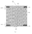
- the evaporator 500 comprises a first header 501, a second header 502, a plurality of heat exchange tubes 503, a plurality of fins 504, and a defrosting tube 505.
- first header 501 is formed with a first refrigerant port 5010
- second header 502 is formed with a second refrigerant port 5020.
- the first header 501 is used as the inlet header of the evaporator 500
- the second header 502 is used as the outlet header of the evaporator 500
- the first refrigerant port 5010 is used as the refrigerant inlet of the evaporator 500
- the second refrigerant port 5020 is used as the refrigerant outlet of the evaporator 500
- the first refrigerant port 5010 and the second refrigerant port 5020 are the refrigerant inlet pipe and the refrigerant outlet pipe respectively.
- Each heat exchange tube 503 such as flat tube is connected between the first and second headers 501, 502 to communicate the first and second headers 501, 502.
- the plurality of fins 504 are interposed between adjacent heat exchange tubes 503 respectively.
- a first end of the defrosting tube 505 is connected to one header of the first and second headers 501, 502 to communicate with an interior of the one header, in which a position of the first end of the defrosting tube 505 connected to the one header is spaced apart from the one end of the one header formed with the refrigerant port by a predetermined distance.
- the defrosting tube 505 is connected to the inlet header 501. More particularly, the first end of the defrosting tube 505 is connected to a substantially middle portion of the inlet header 501. An angle between the axis of the defrosting tube 505 and the axis (i.e., the length direction of each heat exchange tube 503) of each heat exchange tube 503 is substantially about 90 degrees.
- Figs. 3-4 show the evaporator 500 according to another embodiment of the present disclosure, in which the first end of the defrosting tube 505 is connected to the substantially middle portion of the inlet header 501.
- An angle ⁇ between the axis of the defrosting tube 505 and the axis of each heat exchange tube is between about 45 degrees and about 315 degrees.
- Figs. 5-6 show the evaporator 500 according to yet another embodiment of the present disclosure, in which two defrosting tubes 505 are connected to the inlet header 501 respectively and spaced apart from each other in the length direction of the inlet header 501. Both the distance from the left defrosting tube 505 to the left end of the inlet header 501 and the distance from the right defrosting tube 505 to the right end of the inlet header 501 are greater than about 100 millimeters, thus further improving the defrosting effect. It should be appreciated that the number of the defrosting tubes 505 are not limited to this, and any suitable number of defrosting tube 505 may be disposed according to particular applications.
- the inlet header 501 is formed with a refrigerant guide tube 506 having an open end and a closed end and with a plurality of openings such as a plurality of noncircular slots, in a length direction of the refrigerant guide tube 506.
- the open end of the refrigerant guide tube 506 is extended out from the refrigerant inlet of the inlet header 501. More particularly, the open end of the refrigerant guide tube 506 is connected to the refrigerant inlet pipe 5010.
- a refrigerant guide tube 507 having an open end and a closed end is inserted into the outlet header 502 and formed with a plurality of openings such as a plurality of noncircular slots, in a length direction of the refrigerant guide tube 507.
- the open end of the refrigerant guide tube 507 is extended out from the refrigerant outlet of the outlet header 502. More particularly, the open end of the refrigerant guide tube 507 is connected to the refrigerant outlet pipe 5020.
- the defrosting tube 505 may also be connected to the outlet header 502. Similarly, the position of the first end of the defrosting tube 505 connected to the outlet header 502 is spaced apart from the one end of the outlet header 502, for example, the first end of the defrosting tube 505 is connected to a substantially middle portion of the outlet header 502.
- the defrosting tube 505 is connected to the inlet header 501 or the outlet header 502
- the refrigerant enters into the inlet header 501 or the outlet header 502 from the defrosting tube 505, thus improving the defrosting speed, shortening the defrosting time, and improving the energy efficiency of the refrigeration system.
- the refrigeration system (e.g., a heat pump system) according to embodiments of the present disclosure comprises a compressor 100, a four-way valve 200, a condenser 300, a throttle mechanism 400, an evaporator 500, and a refrigerant switching unit.
- the four-way valve 200 has first to fourth valve ports (in Fig. 7 , which are the left valve port, the upper valve port, the right valve port and the lower valve port respectively), in which the first valve port and the third valve port of the four-way valve 200 are connected to the compressor 100.
- An inlet of the condenser 300 is connected to the second valve port of the four-way valve 200.
- An inlet of the throttle mechanism 400 e.g., an expansion valve
- the evaporator 500 is connected between the fourth valve port of the four-way valve 200 and an outlet of the throttle mechanism 400.
- the refrigerant switching unit is connected to the evaporator 500, connected between the fourth valve port of the four-way valve 200 and the outlet of the throttle mechanism 400, configured to allow the refrigerant to enter into the inlet header 501 from the four-way valve 200 through the throttle mechanism 400 and flow out of the outlet header 502 to return to the four-way valve 200 when the refrigeration system is in a normal operation mode, and configured to allow the refrigerant to enter into the one header from the four-way valve 200 through the defrosting tube 505 and flow out of the other of the inlet and outlet headers 501, 502 to return to the four-way valve 200 through the throttle mechanism 400 when the refrigeration system is in a defrosting operation mode.
- an indoor unit is used as the condenser 300, and a fan F is driven by a motor M, such that the hot air heated by the condenser 300 is blown into a room for heating.
- the refrigerant switching unit comprises a first valve A, a second valve B, a third valve C and a fourth valve D.
- the first valve A is connected between the fourth valve port of the four-way valve 200 and the refrigerant outlet 5020 of the outlet header 502
- a first side of the second valve B is connected between the first valve A and the second refrigerant port 5020 of the second header 502
- a second side of the second valve B is connected to the throttle mechanism 400
- a first side of the third valve C is connected between the second side of the second valve B and the throttle mechanism 400
- a second side of the third valve C is connected to the refrigerant outlet 5010 of the inlet header 501
- a first end of the defrosting tube 505 is connected to a substantially middle portion of the inlet header 501
- the fourth valve D is connected between the fourth valve port of the four-way valve 200 and a second end of the defrosting tube 505.
- the first end of the defrosting tube 505 is connected to the inlet header 501.
- the first valve A and the third valve C are opened, and the second valve B and the fourth valve D are closed. Therefore, the refrigerant enters into the four-way valve 200 from the compressor 100 through the third valve port of the four-way valve 200, into the condenser 300 through the second valve port of the four-way valve 200 along the direction shown by solid arrows S, and then into the throttle mechanism 400 along the direction shown by the solid arrows S.
- the refrigerant enters into the inlet header 501 through the refrigerant inlet pipe 5010 of the inlet header 501, for example, may be distributed in the inlet header 501 through the refrigerant guide tube 506, thus eliminating gas-liquid separation.
- the refrigerant enters into each heat exchange tube 503 from the inlet header 501, and then enters into the outlet header 502 of the evaporator 500 after exchanging heat with the environment.
- the refrigerant flowing out of the outlet header 502 (for example, from the refrigerant outlet pipe 5020) is returned to the four-way valve 200 through the first valve A and the fourth valve port of the four-way valve 200, and then enters into the compressor 100 from the first valve port of the four-way valve 200.
- the circulation of the refrigerant is achieved.
- the refrigeration system When defrosting is needed, the refrigeration system is switched to operate in the defrosting operation mode. At this time, the first valve A and the third valve C are closed, and the second valve B and the fourth valve D are opened.
- the refrigerant enters into the defrosting tube 505 from the fourth valve port of the four-way valve 200 through the fourth valve D along the direction shown by dashed arrows N, and then enters into the inlet header 501 of the evaporator 500 from the defrosting tube 505, for example, into the inlet header 501 from the substantially middle portion of the inlet header 501, thus defrosting the evaporator 500 with higher defrosting speed.
- the refrigerant flows into the outlet header 502 along the plurality of heat exchange tubes 503, and then flows out from the refrigerant outlet pipe 5020. Because the first valve A and the third valve C are closed, the refrigerant flowing out of the outlet header 502 may be only returned to the four-way valve 200 through the throttle mechanism 400, the condenser 300, and the third valve port of the four-way valve 200.
- the gaseous refrigerant when defrosting is needed, the gaseous refrigerant enters into the inlet header 501 from the defrosting tube 505, and bypass the refrigerant guide tube 506, thus reducing the flow resistance greatly, increasing the flow rate of the refrigerant, and improving the defrosting speed.
- the refrigeration system e.g., using the refrigerant of R407C
- the high-temperature gaseous refrigerant enters from the inlet header 501, thus accelerating melting of the frost directly and helping evaporation of melt water after defrosting.
- the defrosting tube 505 the defrosting process of the refrigeration system may be greatly accelerated, the defrosting time may be shortened, and the defrosting effect may be enhanced, thus reducing the fluctuation of indoor temperature and improving the comfort degree. Moreover, reverse circulation of the refrigerant in the evaporator 500 may not be required.
- the first end of the defrosting tube 505 is connected to the outlet header 502.
- the first valve A and the third valve C are opened, and the second valve B and the fourth valve D are closed.
- the first valve A and the second valve B are closed, and the third valve C and the fourth valve D are opened.
- the third valve C is normally opened, and the second valve B is normally closed.
- the refrigerant enters into the outlet header 502 from the defrosting tube 505, into the inlet header 501 through the plurality of heat exchange tubes 503, and then is retuned to the four-way valve 200 through the throttle mechanism 400 and the condenser 300.
- Other operations of the refrigeration system in the normal operation mode and the defrosting operation mode will not be described in detail here.
- the defrosting tube 505 is connected to the outlet header 502, which may help rapid melting of frost at the upper portion of the evaporator 500.
- the first end of the defrosting tube 505 is connected to the outlet header 502, and the refrigerant switching unit comprises a first valve A connected between the fourth valve port of the four-way valve 200 and the refrigerant outlet 5020 of the outlet header 502 and a fourth valve D connected between the fourth valve port of the four-way valve 200 and a second end of the defrosting tube 505.
- the first valve A When the refrigeration system is in the normal operation mode, the first valve A is opened, and the fourth valve D is closed. When the refrigeration system is in the defrosting operation mode, the first valve A is closed, and the fourth valve D is opened.
- the embodiment shown in Fig. 9 is different from the embodiment shown in Fig. 8 in that the normally closed second valve B and the normally opened third valve C are omitted, a position in which the second valve B is located is cut off, and a position in which the third valve C is located is replaced by a pipe, thus reducing the cost and the control complexity.
- the operation of the refrigeration system shown in Fig. 9 is similar to that of the refrigeration system shown in Fig. 8 , so that detailed description thereof will be omitted here.
- the first end of the defrosting tube 505 is connected to the outlet header 502
- a second end of the defrosting tube 505 is connected to the fourth valve port of the four-way valve 200
- the refrigerant switching unit comprises a first valve A connected between the fourth valve port of the four-way valve 200 and the refrigerant outlet 5020 of the outlet header 502.
- the first valve A When the refrigeration system is in the normal operation mode, the first valve A is opened, and the refrigerant is returned to the four-way valve 200 from the outlet header 502 through the first valve A. Certainly, a small amount of the refrigerant is returned to the four-way valve 200 from the defrosting tube 505.
- the first valve A When the refrigeration system is in the defrosting operation mode, the first valve A is closed, and the refrigerant enters into the outlet header 502 from the defrosting tube 505 and then is returned to the four-way valve 200 through the plurality of heat exchange tubes 503, the inlet header 501, the throttle mechanism 400 and the condenser 300.
- the evaporator 500 of the refrigeration system only has one defrosting tube 505.
- the defrosting tubes 505 may be connected to the inlet header 501 and the outlet header 502 respectively.
- the defrosting tubes 505 connected to the inlet header 501 and the outlet header 502 respectively may have respective refrigerant switching units.
Landscapes
- Engineering & Computer Science (AREA)
- Physics & Mathematics (AREA)
- Thermal Sciences (AREA)
- Mechanical Engineering (AREA)
- General Engineering & Computer Science (AREA)
- Defrosting Systems (AREA)
- Heat-Exchange Devices With Radiators And Conduit Assemblies (AREA)
- Air-Conditioning For Vehicles (AREA)
Abstract
Description
- The present disclosure relates to refrigeration field, and more particularly to an evaporator and a refrigeration system comprising the same.
- When a refrigeration system, such as the refrigeration system of an air conditioner, is operated in winter and the ambient temperature is very low, the evaporating temperature of the evaporator will be less than zero degree, and consequently the refrigeration system needs to be defrosted. With the conventional refrigeration system, full reverse circulation is used for defrosting, that is, the condenser is used as an evaporator and the evaporator is used as a condenser.
- With the conventional refrigeration system, when defrosting is performed, the indoor ambient temperature will be reduced, thus causing comfort degree to be reduced. On the other hand, defrosting will cause indoor environment heat supply to be broken off, thus reducing the energy efficiency of the system.
- In addition, because refrigerant guide pipes are usually disposed within the inlet header and the outlet header of the evaporator, during defrosting, the flow resistance of the refrigerant is very large, and the refrigerant may not pass through the evaporator in large quantities rapidly, such that the defrosting speed is low. In the refrigeration system using a refrigerant (for example, R407C with large temperature glide), because the frosted position is usually adjacent to the refrigerant inlet of the heat exchanger, defrosting may not be rapidly performed by reverse circulation defrosting mode of introducing the gaseous refrigerant from the outlet header, such that the defrosting time is long and the operating efficiency of the system is low.
- Embodiments of the present disclosure seek to solve at least one of the problems existing in the prior art to at least some extent. Accordingly, an evaporator is provided, by which the defrosting time is short, the defrosting speed is high, and the operation efficiency is improved. Further, a refrigeration system comprising the above-mentioned evaporator is provided, which may reduce the fluctuation of indoor temperature.
- The evaporator according to embodiments of the present disclosure comprises: a first header having one end formed with a first refrigerant port; a second header having one end formed with a second refrigerant port; a plurality of heat exchange tubes each connected between the first and second headers to communicate the first and second headers; a plurality of fins interposed between adjacent heat exchange tubes respectively, and a defrosting tube defining a first end connected to one header of the first and second headers to communicate with an interior of the one header, in which a position of the first end of the defrosting tube connected to the one header is spaced apart from the one end of the one header by a predetermined distance.
- With the evaporator according to embodiments of the present disclosure, because the defrosting tube is connected to the first or second header, when the evaporator needs to be defrosted, the refrigerant enters into the first or second header from the defrosting tube, thus increasing the defrosting speed, shortening the defrosting time, and improving the energy efficiency of the refrigeration system.
- Preferably, the first end of the defrosting tube is connected to a middle portion of the one header.
- Preferably, an angle between an axis of the defrosting tube and an axis of each heat exchange tube is between about 45 degrees and about 315 degrees.
- Preferably, the predetermined distance is greater than about 100 millimeters.
- Preferably, the one header is formed with a refrigerant guide tube having an open end and a closed end and formed with a plurality of openings, the open end of the refrigerant guide tube extending out from a refrigerant port of the one header.
- The refrigeration system according to embodiments of the present disclosure comprises: a compressor; a four-way valve having first to fourth valve ports, in which the first valve port and the third valve port are connected to the compressor; a condenser having an inlet connected to the second valve port of the four-way valve; a throttle mechanism having an inlet connected to an outlet of the condenser; an evaporator connected between the fourth valve port of the four-way valve and an outlet of the throttle mechanism, the evaporator being the evaporator according to the above embodiments of the present disclosure; and a refrigerant switching unit connected to the evaporator, connected between the fourth valve port of the four-way valve and the outlet of the throttle mechanism, configured to allow a refrigerant to enter into the first header from the four-way valve through the throttle mechanism and flow out of the second header to return to the four-way valve when the refrigeration system is in a normal operation mode, and configured to allow the refrigerant to enter into the one header from the four-way valve through the defrosting tube and flow out of the other of the first and second headers to return to the four-way valve through the throttle mechanism when the refrigeration system is in a defrosting operation mode.
- Preferably, the refrigerant switching unit comprises first to fourth valves, the first valve is connected between the fourth valve port of the four-way valve and the second refrigerant port of the second header, a first side of the second valve is connected between the first valve and the second refrigerant port of the second header, a second side of the second valve is connected to the throttle mechanism, a first side of the third valve is connected between the second side of the second valve and the throttle mechanism, a second side of the third valve is connected to the first refrigerant port of the first header, and the fourth valve is connected between the fourth valve port of the four-way valve and a second end of the defrosting tube.
- Preferably, the first end of the defrosting tube is connected to the first header or the second header.
- Preferably, the first end of the defrosting tube is connected to the second header, and the refrigerant switching unit comprises a first valve connected between the fourth valve port of the four-way valve and the second refrigerant port of the second header and a fourth valve connected between the fourth valve port of the four-way valve and a second end of the defrosting tube.
- Preferably, the first end of the defrosting tube is connected to the second header, a second end of the defrosting tube is connected to the fourth valve port of the four-way valve, and the refrigerant switching unit comprises a first valve connected between the fourth valve port of the four-way valve and the second refrigerant port of the second header.
- Additional aspects and advantages of the embodiments of the present disclosure will be given in part in the following descriptions, become apparent in part from the following descriptions, or be learned from the practice of the embodiments of the present disclosure.
- These and other aspects and advantages of the disclosure will become apparent and more readily appreciated from the following descriptions taken in conjunction with the drawings in which:
-
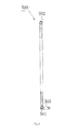
Fig. 1 is a plan view of an evaporator according to an embodiment of the present disclosure; -
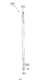
Fig. 2 is a side view of the evaporator shown inFig. 1 ; -
Fig. 3 is a plan view of an evaporator according to another embodiment of the present disclosure; -
Fig. 4 is a side view of the evaporator shown inFig. 3 ; -
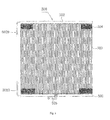
Fig. 5 is a plan view of an evaporator according to yet another embodiment of the present disclosure; -
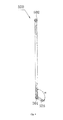
Fig. 6 is a side view of the evaporator shown inFig. 5 ; -
Fig. 7 is a schematic diagram of a refrigeration system according to an embodiment of the present disclosure; -
Fig. 8 is a schematic diagram of a refrigeration system according to another embodiment of the present disclosure; -
Fig. 9 is a schematic diagram of a refrigeration system according to yet another embodiment of the present disclosure; and -
Fig. 10 is a schematic diagram of a refrigeration system according to still another embodiment of the present disclosure. - Embodiments of the present disclosure will be described in detail in the following descriptions, examples of which are shown in the accompanying drawings, in which the same or similar elements and elements having same or similar functions are denoted by like reference numerals throughout the descriptions. The embodiments described herein with reference to the accompanying drawings are explanatory and illustrative, which are used to generally understand the present disclosure. The embodiments shall not be construed to limit the present disclosure.
- It is to be understood that phraseology and terminology used herein with reference to device or element orientation (such as, terms like "longitudinal", "lateral", "front", "rear", "right", "left", "lower", "upper", "horizontal", "vertical", "above", "below", "up", "top", "bottom" as well as derivative thereof such as "horizontally", "downwardly", "upwardly", etc.) are only used to simplify description of the present invention, and do not alone indicate or imply that the device or element referred to must have or operated in a particular orientation.
- Terms concerning attachments, coupling and the like, such as "connected" and "interconnected", refer to a relationship in which structures are secured or attached to one another either directly or indirectly through intervening structures, as well as both movable or rigid attachments or relationships, unless expressly described otherwise. In addition, terms such as "first" and "second" are used herein for purposes of description and are not intended to indicate or imply relative importance or significance.
- The
evaporator 500 according to embodiments of the present disclosure will be described below with reference to the drawings. - The
evaporator 500 according to embodiments of the present disclosure comprises afirst header 501, asecond header 502, a plurality ofheat exchange tubes 503, a plurality offins 504, and adefrosting tube 505. - One end of the
first header 501 is formed with afirst refrigerant port 5010, and one end of thesecond header 502 is formed with asecond refrigerant port 5020. - For convenience, in the following description, the
first header 501 is used as the inlet header of theevaporator 500, thesecond header 502 is used as the outlet header of theevaporator 500, thefirst refrigerant port 5010 is used as the refrigerant inlet of theevaporator 500, thesecond refrigerant port 5020 is used as the refrigerant outlet of theevaporator 500, and thefirst refrigerant port 5010 and thesecond refrigerant port 5020 are the refrigerant inlet pipe and the refrigerant outlet pipe respectively. - Each
heat exchange tube 503 such as flat tube is connected between the first andsecond headers second headers - The plurality of
fins 504 are interposed between adjacentheat exchange tubes 503 respectively. A first end of thedefrosting tube 505 is connected to one header of the first andsecond headers defrosting tube 505 connected to the one header is spaced apart from the one end of the one header formed with the refrigerant port by a predetermined distance. - The
evaporator 500 according to embodiments of the present disclosure will be described below with reference toFigs. 1-2 . As shown inFigs. 1-2 , thedefrosting tube 505 is connected to theinlet header 501. More particularly, the first end of thedefrosting tube 505 is connected to a substantially middle portion of theinlet header 501. An angle between the axis of thedefrosting tube 505 and the axis (i.e., the length direction of each heat exchange tube 503) of eachheat exchange tube 503 is substantially about 90 degrees. -
Figs. 3-4 show theevaporator 500 according to another embodiment of the present disclosure, in which the first end of thedefrosting tube 505 is connected to the substantially middle portion of theinlet header 501. An angle α between the axis of thedefrosting tube 505 and the axis of each heat exchange tube is between about 45 degrees and about 315 degrees. -
Figs. 5-6 show theevaporator 500 according to yet another embodiment of the present disclosure, in which twodefrosting tubes 505 are connected to theinlet header 501 respectively and spaced apart from each other in the length direction of theinlet header 501. Both the distance from the leftdefrosting tube 505 to the left end of theinlet header 501 and the distance from the right defrostingtube 505 to the right end of theinlet header 501 are greater than about 100 millimeters, thus further improving the defrosting effect. It should be appreciated that the number of the defrostingtubes 505 are not limited to this, and any suitable number of defrostingtube 505 may be disposed according to particular applications. - In the embodiment shown in
Figs. 5-6 , theinlet header 501 is formed with arefrigerant guide tube 506 having an open end and a closed end and with a plurality of openings such as a plurality of noncircular slots, in a length direction of therefrigerant guide tube 506. The open end of therefrigerant guide tube 506 is extended out from the refrigerant inlet of theinlet header 501. More particularly, the open end of therefrigerant guide tube 506 is connected to therefrigerant inlet pipe 5010. - Alternatively, as shown in
Fig.6 , arefrigerant guide tube 507 having an open end and a closed end is inserted into theoutlet header 502 and formed with a plurality of openings such as a plurality of noncircular slots, in a length direction of therefrigerant guide tube 507. The open end of therefrigerant guide tube 507 is extended out from the refrigerant outlet of theoutlet header 502. More particularly, the open end of therefrigerant guide tube 507 is connected to therefrigerant outlet pipe 5020. - In some embodiments, the
defrosting tube 505 may also be connected to theoutlet header 502. Similarly, the position of the first end of thedefrosting tube 505 connected to theoutlet header 502 is spaced apart from the one end of theoutlet header 502, for example, the first end of thedefrosting tube 505 is connected to a substantially middle portion of theoutlet header 502. - With the
evaporator 500 according to embodiments of the present disclosure, because thedefrosting tube 505 is connected to theinlet header 501 or theoutlet header 502, when theevaporator 500 needs to be defrosted, the refrigerant enters into theinlet header 501 or theoutlet header 502 from thedefrosting tube 505, thus improving the defrosting speed, shortening the defrosting time, and improving the energy efficiency of the refrigeration system. - The refrigeration system according to embodiments of the present disclosure will be described below with reference to
Fig. 7 . - The refrigeration system (e.g., a heat pump system) according to embodiments of the present disclosure comprises a
compressor 100, a four-way valve 200, acondenser 300, athrottle mechanism 400, anevaporator 500, and a refrigerant switching unit. - More particularly, the four-
way valve 200 has first to fourth valve ports (inFig. 7 , which are the left valve port, the upper valve port, the right valve port and the lower valve port respectively), in which the first valve port and the third valve port of the four-way valve 200 are connected to thecompressor 100. An inlet of thecondenser 300 is connected to the second valve port of the four-way valve 200. An inlet of the throttle mechanism 400 (e.g., an expansion valve) is connected to an outlet of thecondenser 300. Theevaporator 500 is connected between the fourth valve port of the four-way valve 200 and an outlet of thethrottle mechanism 400. - The refrigerant switching unit is connected to the
evaporator 500, connected between the fourth valve port of the four-way valve 200 and the outlet of thethrottle mechanism 400, configured to allow the refrigerant to enter into theinlet header 501 from the four-way valve 200 through thethrottle mechanism 400 and flow out of theoutlet header 502 to return to the four-way valve 200 when the refrigeration system is in a normal operation mode, and configured to allow the refrigerant to enter into the one header from the four-way valve 200 through thedefrosting tube 505 and flow out of the other of the inlet andoutlet headers way valve 200 through thethrottle mechanism 400 when the refrigeration system is in a defrosting operation mode. - For example, when the refrigeration system is operated in a heating mode, an indoor unit is used as the
condenser 300, and a fan F is driven by a motor M, such that the hot air heated by thecondenser 300 is blown into a room for heating. - As shown in
Fig. 7 , the refrigerant switching unit comprises a first valve A, a second valve B, a third valve C and a fourth valve D. The first valve A is connected between the fourth valve port of the four-way valve 200 and therefrigerant outlet 5020 of theoutlet header 502, a first side of the second valve B is connected between the first valve A and the secondrefrigerant port 5020 of thesecond header 502, a second side of the second valve B is connected to thethrottle mechanism 400, a first side of the third valve C is connected between the second side of the second valve B and thethrottle mechanism 400, a second side of the third valve C is connected to therefrigerant outlet 5010 of theinlet header 501, a first end of thedefrosting tube 505 is connected to a substantially middle portion of theinlet header 501, and the fourth valve D is connected between the fourth valve port of the four-way valve 200 and a second end of thedefrosting tube 505. - The normal operation mode and the defrosting operation mode of the refrigeration system according to embodiments of the present disclosure will be described below with reference to
Fig. 7 . - As shown in
Fig. 7 , the first end of thedefrosting tube 505 is connected to theinlet header 501. When the refrigeration system is operated in the normal operation mode, the first valve A and the third valve C are opened, and the second valve B and the fourth valve D are closed. Therefore, the refrigerant enters into the four-way valve 200 from thecompressor 100 through the third valve port of the four-way valve 200, into thecondenser 300 through the second valve port of the four-way valve 200 along the direction shown by solid arrows S, and then into thethrottle mechanism 400 along the direction shown by the solid arrows S. Because the second valve B is closed off and the third valve C is opened, the refrigerant enters into theinlet header 501 through therefrigerant inlet pipe 5010 of theinlet header 501, for example, may be distributed in theinlet header 501 through therefrigerant guide tube 506, thus eliminating gas-liquid separation. The refrigerant enters into eachheat exchange tube 503 from theinlet header 501, and then enters into theoutlet header 502 of theevaporator 500 after exchanging heat with the environment. Because the second valve B and the fourth valve D are closed and the first valve A is opened, the refrigerant flowing out of the outlet header 502 (for example, from the refrigerant outlet pipe 5020) is returned to the four-way valve 200 through the first valve A and the fourth valve port of the four-way valve 200, and then enters into thecompressor 100 from the first valve port of the four-way valve 200. Thus, the circulation of the refrigerant is achieved. - When defrosting is needed, the refrigeration system is switched to operate in the defrosting operation mode. At this time, the first valve A and the third valve C are closed, and the second valve B and the fourth valve D are opened. The refrigerant enters into the
defrosting tube 505 from the fourth valve port of the four-way valve 200 through the fourth valve D along the direction shown by dashed arrows N, and then enters into theinlet header 501 of the evaporator 500 from thedefrosting tube 505, for example, into theinlet header 501 from the substantially middle portion of theinlet header 501, thus defrosting theevaporator 500 with higher defrosting speed. - The refrigerant flows into the
outlet header 502 along the plurality ofheat exchange tubes 503, and then flows out from therefrigerant outlet pipe 5020. Because the first valve A and the third valve C are closed, the refrigerant flowing out of theoutlet header 502 may be only returned to the four-way valve 200 through thethrottle mechanism 400, thecondenser 300, and the third valve port of the four-way valve 200. - Therefore, with the refrigeration system according to embodiments of the present disclosure, when defrosting is needed, the gaseous refrigerant enters into the
inlet header 501 from thedefrosting tube 505, and bypass therefrigerant guide tube 506, thus reducing the flow resistance greatly, increasing the flow rate of the refrigerant, and improving the defrosting speed. On the other hand, for the refrigeration system (e.g., using the refrigerant of R407C) in which most of frosts are accumulated at therefrigerant inlet 5010 of theinlet header 501, the high-temperature gaseous refrigerant enters from theinlet header 501, thus accelerating melting of the frost directly and helping evaporation of melt water after defrosting. Therefore, by thedefrosting tube 505, the defrosting process of the refrigeration system may be greatly accelerated, the defrosting time may be shortened, and the defrosting effect may be enhanced, thus reducing the fluctuation of indoor temperature and improving the comfort degree. Moreover, reverse circulation of the refrigerant in theevaporator 500 may not be required. - The refrigeration system according to another embodiment of the present disclosure will be described below with reference to
Fig. 8 . - In the embodiment shown in
Fig. 8 , the first end of thedefrosting tube 505 is connected to theoutlet header 502. When the refrigeration system is in the normal operation mode, the first valve A and the third valve C are opened, and the second valve B and the fourth valve D are closed. When the refrigeration system is in the defrosting operation mode, the first valve A and the second valve B are closed, and the third valve C and the fourth valve D are opened. In other words, in this case, the third valve C is normally opened, and the second valve B is normally closed. In the defrosting operation mode, the refrigerant enters into theoutlet header 502 from thedefrosting tube 505, into theinlet header 501 through the plurality ofheat exchange tubes 503, and then is retuned to the four-way valve 200 through thethrottle mechanism 400 and thecondenser 300. Other operations of the refrigeration system in the normal operation mode and the defrosting operation mode will not be described in detail here. - With the refrigeration system shown in
Fig. 8 , for some cases in which most of frosts are accumulated at therefrigerant outlet 5020 of theoutlet header 502, thedefrosting tube 505 is connected to theoutlet header 502, which may help rapid melting of frost at the upper portion of theevaporator 500. - The refrigeration system according to yet another embodiment of the present disclosure will be described below with reference to
Fig. 9 . - In the embodiment shown in
Fig. 9 , the first end of thedefrosting tube 505 is connected to theoutlet header 502, and the refrigerant switching unit comprises a first valve A connected between the fourth valve port of the four-way valve 200 and therefrigerant outlet 5020 of theoutlet header 502 and a fourth valve D connected between the fourth valve port of the four-way valve 200 and a second end of thedefrosting tube 505. - When the refrigeration system is in the normal operation mode, the first valve A is opened, and the fourth valve D is closed. When the refrigeration system is in the defrosting operation mode, the first valve A is closed, and the fourth valve D is opened. The embodiment shown in
Fig. 9 is different from the embodiment shown inFig. 8 in that the normally closed second valve B and the normally opened third valve C are omitted, a position in which the second valve B is located is cut off, and a position in which the third valve C is located is replaced by a pipe, thus reducing the cost and the control complexity. The operation of the refrigeration system shown inFig. 9 is similar to that of the refrigeration system shown inFig. 8 , so that detailed description thereof will be omitted here. - The refrigeration system according to still another embodiment of the present disclosure will be described below with reference to
Fig. 10 . - In the embodiment shown in
Fig. 10 , the first end of thedefrosting tube 505 is connected to theoutlet header 502, a second end of thedefrosting tube 505 is connected to the fourth valve port of the four-way valve 200, and the refrigerant switching unit comprises a first valve A connected between the fourth valve port of the four-way valve 200 and therefrigerant outlet 5020 of theoutlet header 502. - When the refrigeration system is in the normal operation mode, the first valve A is opened, and the refrigerant is returned to the four-
way valve 200 from theoutlet header 502 through the first valve A. Certainly, a small amount of the refrigerant is returned to the four-way valve 200 from thedefrosting tube 505. - When the refrigeration system is in the defrosting operation mode, the first valve A is closed, and the refrigerant enters into the
outlet header 502 from thedefrosting tube 505 and then is returned to the four-way valve 200 through the plurality ofheat exchange tubes 503, theinlet header 501, thethrottle mechanism 400 and thecondenser 300. - Only one valve is used by the refrigeration system shown in
Fig. 10 , such that the structure is much simpler, the cost is much lower, and the control is much easier. - In the above-described embodiments, the
evaporator 500 of the refrigeration system only has onedefrosting tube 505. However, it should be noted that any suitable number of thedefrosting tube 505 may be disposed according to requirements, and thedefrosting tubes 505 may be connected to theinlet header 501 and theoutlet header 502 respectively. Certainly, thedefrosting tubes 505 connected to theinlet header 501 and theoutlet header 502 respectively may have respective refrigerant switching units. - Reference throughout this specification to "an embodiment", "some embodiments", "one embodiment", "an example", "a specific examples", or "some examples" means that a particular feature, structure, material, or characteristic described in connection with the embodiment or example is included in at least one embodiment or example of the disclosure. Thus, the appearances of the phrases such as "in some embodiments", "in one embodiment", "in an embodiment", "an example", "a specific examples", or "some examples" in various places throughout this specification are not necessarily referring to the same embodiment or example of the disclosure. Furthermore, the particular features, structures, materials, or characteristics may be combined in any suitable manner in one or more embodiments or examples.
- Although explanatory embodiments have been shown and described, it would be appreciated by those skilled in the art that changes, alternatives, and modifications may be made in the embodiments without departing from spirit and principles of the disclosure. Such changes, alternatives, and modifications all fall into the scope of the claims and their equivalents.
Claims (10)
- An evaporator, comprising:a first header having one end formed with a first refrigerant port;a second header having one end formed with a second refrigerant port;a plurality of heat exchange tubes each connected between the first and second headers to communicate the first and second headers;a plurality of fins interposed between adjacent heat exchange tubes respectively, anda defrosting tube defining a first end connected to one header of the first and second headers to communicate with an interior of the one header, in which a position of the first end of the defrosting tube connected to the one header is spaced apart from the one end of the one header by a predetermined distance.
- The evaporator according to claim 1, wherein the first end of the defrosting tube is connected to a middle portion of the one header.
- The evaporator according to claim 1, wherein an angle between an axis of the defrosting tube and an axis of each heat exchange tube is between about 45 degrees and about 315 degrees.
- The evaporator according to claim 1, wherein the predetermined distance is greater than about 100 millimeters.
- The evaporator according to claim 1, wherein the one header is formed with a refrigerant guide tube having an open end and a closed end and formed with a plurality of openings, the open end of the refrigerant guide tube extending out from a refrigerant port of the one header.
- A refrigeration system, comprising:a compressor;a four-way valve having first to fourth valve ports, in which the first valve port and the third valve port are connected to the compressor;a condenser having an inlet connected to the second valve port of the four-way valve;a throttle mechanism having an inlet connected to an outlet of the condenser;an evaporator connected between the fourth valve port of the four-way valve and an outlet of the throttle mechanism, the evaporator being the evaporator of any one of claims 1-5; anda refrigerant switching unit connected to the evaporator, connected between the fourth valve port of the four-way valve and the outlet of the throttle mechanism, configured to allow a refrigerant to enter into the first header from the four-way valve through the throttle mechanism and flow out of the second header to return to the four-way valve when the refrigeration system is in a normal operation mode, and configured to allow the refrigerant to enter into the one header from the four-way valve through the defrosting tube and flow out of the other of the first and second headers to return to the four-way valve through the throttle mechanism when the refrigeration system is in a defrosting operation mode.
- The refrigeration system according to claim 6, wherein the refrigerant switching unit comprises first to fourth valves, the first valve is connected between the fourth valve port of the four-way valve and the second refrigerant port of the second header, a first side of the second valve is connected between the first valve and the second refrigerant port of the second header, a second side of the second valve is connected to the throttle mechanism, a first side of the third valve is connected between the second side of the second valve and the throttle mechanism, a second side of the third valve is connected to the first refrigerant port of the first header, and the fourth valve is connected between the fourth valve port of the four-way valve and a second end of the defrosting tube.
- The refrigeration system according to claim 7, wherein the first end of the defrosting tube is connected to the first header or the second header.
- The refrigeration system according to claim 6, wherein the first end of the defrosting tube is connected to the second header, and the refrigerant switching unit comprises a first valve connected between the fourth valve port of the four-way valve and the second refrigerant port of the second header and a fourth valve connected between the fourth valve port of the four-way valve and a second end of the defrosting tube.
- The refrigeration system according to claim 6, wherein the first end of the defrosting tube is connected to the second header, a second end of the defrosting tube is connected to the fourth valve port of the four-way valve, and the refrigerant switching unit comprises a first valve connected between the fourth valve port of the four-way valve and the second refrigerant port of the second header.
Applications Claiming Priority (2)
| Application Number | Priority Date | Filing Date | Title |
|---|---|---|---|
| CN2010105382042A CN102003842B (en) | 2010-11-04 | 2010-11-04 | Evaporator and refrigeration system with same |
| PCT/CN2010/080259 WO2012058844A1 (en) | 2010-11-04 | 2010-12-24 | Evaporator and refrigerating system with said evaporator thereof |
Publications (3)
| Publication Number | Publication Date |
|---|---|
| EP2636973A1 true EP2636973A1 (en) | 2013-09-11 |
| EP2636973A4 EP2636973A4 (en) | 2015-03-04 |
| EP2636973B1 EP2636973B1 (en) | 2020-03-18 |
Family
ID=43811414
Family Applications (1)
| Application Number | Title | Priority Date | Filing Date |
|---|---|---|---|
| EP10859192.6A Active EP2636973B1 (en) | 2010-11-04 | 2010-12-24 | Evaporator and refrigerating system with said evaporator thereof |
Country Status (6)
| Country | Link |
|---|---|
| US (1) | US9285145B2 (en) |
| EP (1) | EP2636973B1 (en) |
| JP (1) | JP5646767B2 (en) |
| KR (1) | KR101504720B1 (en) |
| CN (1) | CN102003842B (en) |
| WO (1) | WO2012058844A1 (en) |
Cited By (1)
| Publication number | Priority date | Publication date | Assignee | Title |
|---|---|---|---|---|
| CN111238090A (en) * | 2020-01-09 | 2020-06-05 | 西安交通大学 | A microchannel evaporator and its control method |
Families Citing this family (9)
| Publication number | Priority date | Publication date | Assignee | Title |
|---|---|---|---|---|
| CN103047727A (en) * | 2013-01-23 | 2013-04-17 | 三花控股集团有限公司 | Heat pump system |
| WO2015177822A1 (en) * | 2014-05-19 | 2015-11-26 | 三菱電機株式会社 | Unit cooler |
| CN105371542B (en) * | 2014-08-28 | 2020-04-28 | 浙江盾安人工环境股份有限公司 | Air conditioning system and defrosting method thereof |
| CN106288532B (en) * | 2016-10-13 | 2018-06-29 | 珠海格力电器股份有限公司 | Heat exchanger assembly, air cooler, refrigerating unit and control method thereof |
| JP7106814B2 (en) * | 2017-02-23 | 2022-07-27 | 株式会社富士通ゼネラル | Heat exchanger |
| CN106958964A (en) * | 2017-03-07 | 2017-07-18 | 杭州三花家电热管理系统有限公司 | Heat pump and its control method and the water heater with the heat pump |
| WO2019008664A1 (en) * | 2017-07-04 | 2019-01-10 | 三菱電機株式会社 | Refrigeration cycle device |
| CN112013502B (en) * | 2019-05-30 | 2022-07-29 | 广东Tcl智能暖通设备有限公司 | Defrosting method of air conditioner heat exchanger and air conditioner |
| CN113932506A (en) * | 2021-10-11 | 2022-01-14 | 青岛海尔空调器有限总公司 | Air conditioner |
Family Cites Families (27)
| Publication number | Priority date | Publication date | Assignee | Title |
|---|---|---|---|---|
| US2678545A (en) * | 1951-02-28 | 1954-05-18 | Philco Corp | Defrostable refrigeration system |
| US4122686A (en) * | 1977-06-03 | 1978-10-31 | Gulf & Western Manufacturing Company | Method and apparatus for defrosting a refrigeration system |
| FR2421352A1 (en) * | 1978-03-29 | 1979-10-26 | Stuckey Trevor | Evaporator for refrigeration system - has water or eutectic substance contained in hollow bodies supported by plates with defrost heaters |
| US4313313A (en) * | 1980-01-17 | 1982-02-02 | Carrier Corporation | Apparatus and method for defrosting a heat exchanger of a refrigeration circuit |
| US4407137A (en) * | 1981-03-16 | 1983-10-04 | Carrier Corporation | Fast defrost heat exchanger |
| JPS6048466A (en) * | 1983-08-24 | 1985-03-16 | 株式会社日立製作所 | Air conditioning equipment |
| JPS60129579A (en) * | 1983-12-17 | 1985-07-10 | 大冷工業株式会社 | Method and device for defrosting cooler |
| JPS61211674A (en) * | 1985-03-18 | 1986-09-19 | 株式会社日立製作所 | Heat pump type air conditioner |
| JPH079331B2 (en) * | 1986-12-26 | 1995-02-01 | 松下電器産業株式会社 | Operation control method for heat pump type air conditioner |
| JPH0760038B2 (en) * | 1988-06-27 | 1995-06-28 | 株式会社西日本精機製作所 | Defroster for refrigerator |
| JPH03195873A (en) * | 1989-12-26 | 1991-08-27 | Matsushita Refrig Co Ltd | Refrigerant flow divider |
| IT1244107B (en) * | 1990-09-28 | 1994-07-05 | Costan Spa | REFRIGERATED REFRIGERANT CIRCUIT AND RELATED DEFROSTING METHOD |
| JP3214874B2 (en) * | 1991-08-29 | 2001-10-02 | 昭和電工株式会社 | Heat exchanger |
| JPH07103625A (en) * | 1993-10-12 | 1995-04-18 | Sanyo Electric Co Ltd | How to operate the ice maker |
| KR970047602A (en) * | 1995-12-29 | 1997-07-26 | 구자홍 | Defroster of evaporator |
| JPH10300271A (en) * | 1997-04-30 | 1998-11-13 | Nippon Light Metal Co Ltd | Outdoor heat exchanger for heat pump air conditioner |
| JP2000062446A (en) * | 1998-08-20 | 2000-02-29 | Zexel Corp | Vehicle air conditioner |
| JP2002221374A (en) * | 2001-01-24 | 2002-08-09 | Kubota Corp | Evaporator for air and heat pump device using the same |
| US7104079B2 (en) * | 2001-07-02 | 2006-09-12 | Sanyo Electric Co., Ltd. | Heat pump |
| AUPR655401A0 (en) | 2001-07-23 | 2001-08-16 | Pacific Ore Technology (Australia) Ltd | Adaptation of bacteria for use in leaching |
| CN1536311A (en) * | 2003-04-11 | 2004-10-13 | 乐金电子(天津)电器有限公司 | Heat-radiating device of heat-exchanger |
| US7171817B2 (en) * | 2004-12-30 | 2007-02-06 | Birgen Daniel J | Heat exchanger liquid refrigerant defrost system |
| CN101248321A (en) * | 2005-06-23 | 2008-08-20 | 卡里尔公司 | Method for defrosting evaporator of refrigeration circuit |
| KR100788302B1 (en) * | 2006-04-13 | 2007-12-27 | 주식회사 코벡엔지니어링 | High speed defrost heat pump |
| CN200972288Y (en) * | 2006-10-24 | 2007-11-07 | 邱致琏 | Improvement of the structure of the evaporator |
| WO2008060270A1 (en) * | 2006-11-13 | 2008-05-22 | Carrier Corporation | Minichannel heat exchanger header insert for distribution |
| CN101839590B (en) * | 2010-02-22 | 2012-03-21 | 三花丹佛斯(杭州)微通道换热器有限公司 | Micro-passage heat exchanger |
-
2010
- 2010-11-04 CN CN2010105382042A patent/CN102003842B/en active Active
- 2010-12-24 JP JP2013536980A patent/JP5646767B2/en active Active
- 2010-12-24 EP EP10859192.6A patent/EP2636973B1/en active Active
- 2010-12-24 WO PCT/CN2010/080259 patent/WO2012058844A1/en not_active Ceased
- 2010-12-24 KR KR1020137014206A patent/KR101504720B1/en active Active
- 2010-12-24 US US13/883,570 patent/US9285145B2/en active Active
Cited By (2)
| Publication number | Priority date | Publication date | Assignee | Title |
|---|---|---|---|---|
| CN111238090A (en) * | 2020-01-09 | 2020-06-05 | 西安交通大学 | A microchannel evaporator and its control method |
| CN111238090B (en) * | 2020-01-09 | 2021-02-02 | 西安交通大学 | Micro-channel evaporator and control method thereof |
Also Published As
| Publication number | Publication date |
|---|---|
| JP2013541691A (en) | 2013-11-14 |
| EP2636973B1 (en) | 2020-03-18 |
| CN102003842B (en) | 2013-04-10 |
| US20130291579A1 (en) | 2013-11-07 |
| EP2636973A4 (en) | 2015-03-04 |
| CN102003842A (en) | 2011-04-06 |
| WO2012058844A1 (en) | 2012-05-10 |
| US9285145B2 (en) | 2016-03-15 |
| KR101504720B1 (en) | 2015-03-20 |
| JP5646767B2 (en) | 2014-12-24 |
| KR20130095296A (en) | 2013-08-27 |
Similar Documents
| Publication | Publication Date | Title |
|---|---|---|
| EP2636973B1 (en) | Evaporator and refrigerating system with said evaporator thereof | |
| JP6685409B2 (en) | Air conditioner | |
| CN106233077B (en) | Air conditioner | |
| JP6087611B2 (en) | Refrigeration cycle and air conditioner equipped with the same | |
| EP2759785B1 (en) | Refrigeration device | |
| JP6768073B2 (en) | Air conditioner | |
| CN101600919B (en) | Multichannel heat exchanger with dissimilar multichannel tubes | |
| US20140026601A1 (en) | Defrosting A Heat Exchanger In A Heat Pump By Diverting Warm Refrigerant To An Exhaust Header | |
| US20110041541A1 (en) | Air Conditioner | |
| JP2009257709A (en) | Air conditioner | |
| WO2013001976A1 (en) | Air conditioner | |
| JP6285172B2 (en) | Air conditioner outdoor unit | |
| WO2013177305A1 (en) | Defrosting a heat exchanger in a heat pump by diverting warm refrigerant to an exhaust header | |
| CN109140725B (en) | Multi-split air conditioning system and defrosting control method thereof | |
| JP5749210B2 (en) | Air conditioner | |
| US9618235B2 (en) | Air conditioner including an indoor auxiliary heat exchanger | |
| JP2013104623A (en) | Refrigeration cycle device and air conditioner with the same | |
| CN114127493B (en) | Air conditioner | |
| EP3379175B1 (en) | Heat pump system | |
| JP2018138826A (en) | Air conditioner | |
| CN110207427B (en) | Heat exchanger, refrigerating system and air conditioner | |
| CN223121568U (en) | Heat exchanger, air conditioner outdoor unit, air conditioner | |
| JP7357137B1 (en) | air conditioner | |
| CN223826523U (en) | Heat exchanger, outdoor unit and air conditioner | |
| US20260029177A1 (en) | Heat exchanger and refrigeration cycle apparatus including heat exchanger |
Legal Events
| Date | Code | Title | Description |
|---|---|---|---|
| PUAI | Public reference made under article 153(3) epc to a published international application that has entered the european phase |
Free format text: ORIGINAL CODE: 0009012 |
|
| 17P | Request for examination filed |
Effective date: 20130603 |
|
| AK | Designated contracting states |
Kind code of ref document: A1 Designated state(s): AL AT BE BG CH CY CZ DE DK EE ES FI FR GB GR HR HU IE IS IT LI LT LU LV MC MK MT NL NO PL PT RO RS SE SI SK SM TR |
|
| DAX | Request for extension of the european patent (deleted) | ||
| A4 | Supplementary search report drawn up and despatched |
Effective date: 20150202 |
|
| RIC1 | Information provided on ipc code assigned before grant |
Ipc: F25B 47/00 20060101ALI20150127BHEP Ipc: F25B 39/02 20060101AFI20150127BHEP Ipc: F28D 1/053 20060101ALI20150127BHEP |
|
| RAP1 | Party data changed (applicant data changed or rights of an application transferred) |
Owner name: SANHUA (HANGZHOU) MICRO CHANNEL HEAT EXCHANGER CO. Owner name: DANFOSS A/S |
|
| STAA | Information on the status of an ep patent application or granted ep patent |
Free format text: STATUS: EXAMINATION IS IN PROGRESS |
|
| 17Q | First examination report despatched |
Effective date: 20170404 |
|
| GRAP | Despatch of communication of intention to grant a patent |
Free format text: ORIGINAL CODE: EPIDOSNIGR1 |
|
| STAA | Information on the status of an ep patent application or granted ep patent |
Free format text: STATUS: GRANT OF PATENT IS INTENDED |
|
| INTG | Intention to grant announced |
Effective date: 20191017 |
|
| GRAS | Grant fee paid |
Free format text: ORIGINAL CODE: EPIDOSNIGR3 |
|
| GRAA | (expected) grant |
Free format text: ORIGINAL CODE: 0009210 |
|
| STAA | Information on the status of an ep patent application or granted ep patent |
Free format text: STATUS: THE PATENT HAS BEEN GRANTED |
|
| AK | Designated contracting states |
Kind code of ref document: B1 Designated state(s): AL AT BE BG CH CY CZ DE DK EE ES FI FR GB GR HR HU IE IS IT LI LT LU LV MC MK MT NL NO PL PT RO RS SE SI SK SM TR |
|
| REG | Reference to a national code |
Ref country code: GB Ref legal event code: FG4D |
|
| REG | Reference to a national code |
Ref country code: DE Ref legal event code: R096 Ref document number: 602010063590 Country of ref document: DE |
|
| REG | Reference to a national code |
Ref country code: AT Ref legal event code: REF Ref document number: 1246359 Country of ref document: AT Kind code of ref document: T Effective date: 20200415 Ref country code: IE Ref legal event code: FG4D |
|
| PG25 | Lapsed in a contracting state [announced via postgrant information from national office to epo] |
Ref country code: RS Free format text: LAPSE BECAUSE OF FAILURE TO SUBMIT A TRANSLATION OF THE DESCRIPTION OR TO PAY THE FEE WITHIN THE PRESCRIBED TIME-LIMIT Effective date: 20200318 Ref country code: FI Free format text: LAPSE BECAUSE OF FAILURE TO SUBMIT A TRANSLATION OF THE DESCRIPTION OR TO PAY THE FEE WITHIN THE PRESCRIBED TIME-LIMIT Effective date: 20200318 Ref country code: NO Free format text: LAPSE BECAUSE OF FAILURE TO SUBMIT A TRANSLATION OF THE DESCRIPTION OR TO PAY THE FEE WITHIN THE PRESCRIBED TIME-LIMIT Effective date: 20200618 |
|
| REG | Reference to a national code |
Ref country code: NL Ref legal event code: MP Effective date: 20200318 |
|
| PG25 | Lapsed in a contracting state [announced via postgrant information from national office to epo] |
Ref country code: BG Free format text: LAPSE BECAUSE OF FAILURE TO SUBMIT A TRANSLATION OF THE DESCRIPTION OR TO PAY THE FEE WITHIN THE PRESCRIBED TIME-LIMIT Effective date: 20200618 Ref country code: LV Free format text: LAPSE BECAUSE OF FAILURE TO SUBMIT A TRANSLATION OF THE DESCRIPTION OR TO PAY THE FEE WITHIN THE PRESCRIBED TIME-LIMIT Effective date: 20200318 Ref country code: HR Free format text: LAPSE BECAUSE OF FAILURE TO SUBMIT A TRANSLATION OF THE DESCRIPTION OR TO PAY THE FEE WITHIN THE PRESCRIBED TIME-LIMIT Effective date: 20200318 Ref country code: SE Free format text: LAPSE BECAUSE OF FAILURE TO SUBMIT A TRANSLATION OF THE DESCRIPTION OR TO PAY THE FEE WITHIN THE PRESCRIBED TIME-LIMIT Effective date: 20200318 Ref country code: GR Free format text: LAPSE BECAUSE OF FAILURE TO SUBMIT A TRANSLATION OF THE DESCRIPTION OR TO PAY THE FEE WITHIN THE PRESCRIBED TIME-LIMIT Effective date: 20200619 |
|
| REG | Reference to a national code |
Ref country code: LT Ref legal event code: MG4D |
|
| PG25 | Lapsed in a contracting state [announced via postgrant information from national office to epo] |
Ref country code: NL Free format text: LAPSE BECAUSE OF FAILURE TO SUBMIT A TRANSLATION OF THE DESCRIPTION OR TO PAY THE FEE WITHIN THE PRESCRIBED TIME-LIMIT Effective date: 20200318 |
|
| PG25 | Lapsed in a contracting state [announced via postgrant information from national office to epo] |
Ref country code: IS Free format text: LAPSE BECAUSE OF FAILURE TO SUBMIT A TRANSLATION OF THE DESCRIPTION OR TO PAY THE FEE WITHIN THE PRESCRIBED TIME-LIMIT Effective date: 20200718 Ref country code: SK Free format text: LAPSE BECAUSE OF FAILURE TO SUBMIT A TRANSLATION OF THE DESCRIPTION OR TO PAY THE FEE WITHIN THE PRESCRIBED TIME-LIMIT Effective date: 20200318 Ref country code: RO Free format text: LAPSE BECAUSE OF FAILURE TO SUBMIT A TRANSLATION OF THE DESCRIPTION OR TO PAY THE FEE WITHIN THE PRESCRIBED TIME-LIMIT Effective date: 20200318 Ref country code: PT Free format text: LAPSE BECAUSE OF FAILURE TO SUBMIT A TRANSLATION OF THE DESCRIPTION OR TO PAY THE FEE WITHIN THE PRESCRIBED TIME-LIMIT Effective date: 20200812 Ref country code: CZ Free format text: LAPSE BECAUSE OF FAILURE TO SUBMIT A TRANSLATION OF THE DESCRIPTION OR TO PAY THE FEE WITHIN THE PRESCRIBED TIME-LIMIT Effective date: 20200318 Ref country code: LT Free format text: LAPSE BECAUSE OF FAILURE TO SUBMIT A TRANSLATION OF THE DESCRIPTION OR TO PAY THE FEE WITHIN THE PRESCRIBED TIME-LIMIT Effective date: 20200318 Ref country code: SM Free format text: LAPSE BECAUSE OF FAILURE TO SUBMIT A TRANSLATION OF THE DESCRIPTION OR TO PAY THE FEE WITHIN THE PRESCRIBED TIME-LIMIT Effective date: 20200318 Ref country code: EE Free format text: LAPSE BECAUSE OF FAILURE TO SUBMIT A TRANSLATION OF THE DESCRIPTION OR TO PAY THE FEE WITHIN THE PRESCRIBED TIME-LIMIT Effective date: 20200318 |
|
| REG | Reference to a national code |
Ref country code: AT Ref legal event code: MK05 Ref document number: 1246359 Country of ref document: AT Kind code of ref document: T Effective date: 20200318 |
|
| REG | Reference to a national code |
Ref country code: DE Ref legal event code: R097 Ref document number: 602010063590 Country of ref document: DE |
|
| PLBE | No opposition filed within time limit |
Free format text: ORIGINAL CODE: 0009261 |
|
| STAA | Information on the status of an ep patent application or granted ep patent |
Free format text: STATUS: NO OPPOSITION FILED WITHIN TIME LIMIT |
|
| PG25 | Lapsed in a contracting state [announced via postgrant information from national office to epo] |
Ref country code: AT Free format text: LAPSE BECAUSE OF FAILURE TO SUBMIT A TRANSLATION OF THE DESCRIPTION OR TO PAY THE FEE WITHIN THE PRESCRIBED TIME-LIMIT Effective date: 20200318 Ref country code: DK Free format text: LAPSE BECAUSE OF FAILURE TO SUBMIT A TRANSLATION OF THE DESCRIPTION OR TO PAY THE FEE WITHIN THE PRESCRIBED TIME-LIMIT Effective date: 20200318 Ref country code: ES Free format text: LAPSE BECAUSE OF FAILURE TO SUBMIT A TRANSLATION OF THE DESCRIPTION OR TO PAY THE FEE WITHIN THE PRESCRIBED TIME-LIMIT Effective date: 20200318 |
|
| 26N | No opposition filed |
Effective date: 20201221 |
|
| PG25 | Lapsed in a contracting state [announced via postgrant information from national office to epo] |
Ref country code: PL Free format text: LAPSE BECAUSE OF FAILURE TO SUBMIT A TRANSLATION OF THE DESCRIPTION OR TO PAY THE FEE WITHIN THE PRESCRIBED TIME-LIMIT Effective date: 20200318 |
|
| PG25 | Lapsed in a contracting state [announced via postgrant information from national office to epo] |
Ref country code: SI Free format text: LAPSE BECAUSE OF FAILURE TO SUBMIT A TRANSLATION OF THE DESCRIPTION OR TO PAY THE FEE WITHIN THE PRESCRIBED TIME-LIMIT Effective date: 20200318 |
|
| REG | Reference to a national code |
Ref country code: CH Ref legal event code: PL |
|
| GBPC | Gb: european patent ceased through non-payment of renewal fee |
Effective date: 20201224 |
|
| PG25 | Lapsed in a contracting state [announced via postgrant information from national office to epo] |
Ref country code: MC Free format text: LAPSE BECAUSE OF FAILURE TO SUBMIT A TRANSLATION OF THE DESCRIPTION OR TO PAY THE FEE WITHIN THE PRESCRIBED TIME-LIMIT Effective date: 20200318 |
|
| REG | Reference to a national code |
Ref country code: BE Ref legal event code: MM Effective date: 20201231 |
|
| PG25 | Lapsed in a contracting state [announced via postgrant information from national office to epo] |
Ref country code: IE Free format text: LAPSE BECAUSE OF NON-PAYMENT OF DUE FEES Effective date: 20201224 Ref country code: LU Free format text: LAPSE BECAUSE OF NON-PAYMENT OF DUE FEES Effective date: 20201224 |
|
| PG25 | Lapsed in a contracting state [announced via postgrant information from national office to epo] |
Ref country code: CH Free format text: LAPSE BECAUSE OF NON-PAYMENT OF DUE FEES Effective date: 20201231 Ref country code: GB Free format text: LAPSE BECAUSE OF NON-PAYMENT OF DUE FEES Effective date: 20201224 Ref country code: LI Free format text: LAPSE BECAUSE OF NON-PAYMENT OF DUE FEES Effective date: 20201231 |
|
| PG25 | Lapsed in a contracting state [announced via postgrant information from national office to epo] |
Ref country code: MT Free format text: LAPSE BECAUSE OF FAILURE TO SUBMIT A TRANSLATION OF THE DESCRIPTION OR TO PAY THE FEE WITHIN THE PRESCRIBED TIME-LIMIT Effective date: 20200318 Ref country code: CY Free format text: LAPSE BECAUSE OF FAILURE TO SUBMIT A TRANSLATION OF THE DESCRIPTION OR TO PAY THE FEE WITHIN THE PRESCRIBED TIME-LIMIT Effective date: 20200318 |
|
| PG25 | Lapsed in a contracting state [announced via postgrant information from national office to epo] |
Ref country code: MK Free format text: LAPSE BECAUSE OF FAILURE TO SUBMIT A TRANSLATION OF THE DESCRIPTION OR TO PAY THE FEE WITHIN THE PRESCRIBED TIME-LIMIT Effective date: 20200318 Ref country code: AL Free format text: LAPSE BECAUSE OF FAILURE TO SUBMIT A TRANSLATION OF THE DESCRIPTION OR TO PAY THE FEE WITHIN THE PRESCRIBED TIME-LIMIT Effective date: 20200318 |
|
| PG25 | Lapsed in a contracting state [announced via postgrant information from national office to epo] |
Ref country code: BE Free format text: LAPSE BECAUSE OF NON-PAYMENT OF DUE FEES Effective date: 20201231 |
|
| P01 | Opt-out of the competence of the unified patent court (upc) registered |
Effective date: 20230510 |
|
| REG | Reference to a national code |
Ref country code: DE Ref legal event code: R081 Ref document number: 602010063590 Country of ref document: DE Owner name: SANHUA (HANGZHOU) MICRO CHANNEL HEAT EXCHANGER, CN Free format text: FORMER OWNERS: DANFOSS A/S, NORDBORG, DK; SANHUA (HANGZHOU) MICRO CHANNEL HEAT EXCHANGER CO. LTD, HANGZHOU, ZHEJIANG, CN |
|
| PGFP | Annual fee paid to national office [announced via postgrant information from national office to epo] |
Ref country code: DE Payment date: 20241126 Year of fee payment: 15 |
|
| PGFP | Annual fee paid to national office [announced via postgrant information from national office to epo] |
Ref country code: FR Payment date: 20241121 Year of fee payment: 15 |
|
| PGFP | Annual fee paid to national office [announced via postgrant information from national office to epo] |
Ref country code: IT Payment date: 20241128 Year of fee payment: 15 |
|
| PGFP | Annual fee paid to national office [announced via postgrant information from national office to epo] |
Ref country code: TR Payment date: 20241212 Year of fee payment: 15 |