EP2636948B1 - LED lamp and method for operating such a lamp - Google Patents
LED lamp and method for operating such a lamp Download PDFInfo
- Publication number
- EP2636948B1 EP2636948B1 EP13158328.8A EP13158328A EP2636948B1 EP 2636948 B1 EP2636948 B1 EP 2636948B1 EP 13158328 A EP13158328 A EP 13158328A EP 2636948 B1 EP2636948 B1 EP 2636948B1
- Authority
- EP
- European Patent Office
- Prior art keywords
- light
- led lamp
- emitting diodes
- retrofit led
- driver circuit
- Prior art date
- Legal status (The legal status is an assumption and is not a legal conclusion. Google has not performed a legal analysis and makes no representation as to the accuracy of the status listed.)
- Not-in-force
Links
- 238000000034 method Methods 0.000 title claims description 8
- 230000003287 optical effect Effects 0.000 claims description 10
- 230000001419 dependent effect Effects 0.000 description 10
- 238000009434 installation Methods 0.000 description 7
- 229910052736 halogen Inorganic materials 0.000 description 4
- 150000002367 halogens Chemical class 0.000 description 4
- 238000011161 development Methods 0.000 description 3
- 230000018109 developmental process Effects 0.000 description 3
- 238000005286 illumination Methods 0.000 description 3
- 230000005855 radiation Effects 0.000 description 3
- 239000004065 semiconductor Substances 0.000 description 3
- 230000005540 biological transmission Effects 0.000 description 2
- 230000000694 effects Effects 0.000 description 2
- 238000005516 engineering process Methods 0.000 description 2
- 239000000969 carrier Substances 0.000 description 1
- 239000003086 colorant Substances 0.000 description 1
- 238000001514 detection method Methods 0.000 description 1
- 238000010586 diagram Methods 0.000 description 1
- 238000011156 evaluation Methods 0.000 description 1
- QSHDDOUJBYECFT-UHFFFAOYSA-N mercury Chemical compound [Hg] QSHDDOUJBYECFT-UHFFFAOYSA-N 0.000 description 1
- 229910052753 mercury Inorganic materials 0.000 description 1
- 230000000630 rising effect Effects 0.000 description 1
- 229910052710 silicon Inorganic materials 0.000 description 1
- 239000010703 silicon Substances 0.000 description 1
- 150000003377 silicon compounds Chemical class 0.000 description 1
- 239000000758 substrate Substances 0.000 description 1
- 230000008646 thermal stress Effects 0.000 description 1
Images

Classifications
-
- F—MECHANICAL ENGINEERING; LIGHTING; HEATING; WEAPONS; BLASTING
- F21—LIGHTING
- F21V—FUNCTIONAL FEATURES OR DETAILS OF LIGHTING DEVICES OR SYSTEMS THEREOF; STRUCTURAL COMBINATIONS OF LIGHTING DEVICES WITH OTHER ARTICLES, NOT OTHERWISE PROVIDED FOR
- F21V23/00—Arrangement of electric circuit elements in or on lighting devices
- F21V23/04—Arrangement of electric circuit elements in or on lighting devices the elements being switches
- F21V23/0442—Arrangement of electric circuit elements in or on lighting devices the elements being switches activated by means of a sensor, e.g. motion or photodetectors
- F21V23/0492—Arrangement of electric circuit elements in or on lighting devices the elements being switches activated by means of a sensor, e.g. motion or photodetectors the sensor detecting a change in orientation, a movement or an acceleration of the lighting device, e.g. a tilt switch
-
- F—MECHANICAL ENGINEERING; LIGHTING; HEATING; WEAPONS; BLASTING
- F21—LIGHTING
- F21K—NON-ELECTRIC LIGHT SOURCES USING LUMINESCENCE; LIGHT SOURCES USING ELECTROCHEMILUMINESCENCE; LIGHT SOURCES USING CHARGES OF COMBUSTIBLE MATERIAL; LIGHT SOURCES USING SEMICONDUCTOR DEVICES AS LIGHT-GENERATING ELEMENTS; LIGHT SOURCES NOT OTHERWISE PROVIDED FOR
- F21K9/00—Light sources using semiconductor devices as light-generating elements, e.g. using light-emitting diodes [LED] or lasers
- F21K9/20—Light sources comprising attachment means
- F21K9/23—Retrofit light sources for lighting devices with a single fitting for each light source, e.g. for substitution of incandescent lamps with bayonet or threaded fittings
- F21K9/232—Retrofit light sources for lighting devices with a single fitting for each light source, e.g. for substitution of incandescent lamps with bayonet or threaded fittings specially adapted for generating an essentially omnidirectional light distribution, e.g. with a glass bulb
-
- F—MECHANICAL ENGINEERING; LIGHTING; HEATING; WEAPONS; BLASTING
- F21—LIGHTING
- F21Y—INDEXING SCHEME ASSOCIATED WITH SUBCLASSES F21K, F21L, F21S and F21V, RELATING TO THE FORM OR THE KIND OF THE LIGHT SOURCES OR OF THE COLOUR OF THE LIGHT EMITTED
- F21Y2107/00—Light sources with three-dimensionally disposed light-generating elements
- F21Y2107/30—Light sources with three-dimensionally disposed light-generating elements on the outer surface of cylindrical surfaces, e.g. rod-shaped supports having a circular or a polygonal cross section
-
- F—MECHANICAL ENGINEERING; LIGHTING; HEATING; WEAPONS; BLASTING
- F21—LIGHTING
- F21Y—INDEXING SCHEME ASSOCIATED WITH SUBCLASSES F21K, F21L, F21S and F21V, RELATING TO THE FORM OR THE KIND OF THE LIGHT SOURCES OR OF THE COLOUR OF THE LIGHT EMITTED
- F21Y2115/00—Light-generating elements of semiconductor light sources
- F21Y2115/10—Light-emitting diodes [LED]
-
- Y—GENERAL TAGGING OF NEW TECHNOLOGICAL DEVELOPMENTS; GENERAL TAGGING OF CROSS-SECTIONAL TECHNOLOGIES SPANNING OVER SEVERAL SECTIONS OF THE IPC; TECHNICAL SUBJECTS COVERED BY FORMER USPC CROSS-REFERENCE ART COLLECTIONS [XRACs] AND DIGESTS
- Y02—TECHNOLOGIES OR APPLICATIONS FOR MITIGATION OR ADAPTATION AGAINST CLIMATE CHANGE
- Y02B—CLIMATE CHANGE MITIGATION TECHNOLOGIES RELATED TO BUILDINGS, e.g. HOUSING, HOUSE APPLIANCES OR RELATED END-USER APPLICATIONS
- Y02B20/00—Energy efficient lighting technologies, e.g. halogen lamps or gas discharge lamps
- Y02B20/30—Semiconductor lamps, e.g. solid state lamps [SSL] light emitting diodes [LED] or organic LED [OLED]
Definitions
- the present invention relates to an LED lamp with one or more LEDs as a light source.
- the present invention relates to a so-called retrofit LED lamp, which is intended as a replacement for classic halogen lamps or incandescent lamps, and a method for operating such a lamp.
- LEDs organic light-emitting diodes
- Light-emitting diodes are distinguished by their high light efficiency and longevity compared to conventional light sources such as incandescent lamps or fluorescent lamps.
- these are generally light sources with extremely small dimensions, which allows a very flexible use.
- another advantage of these light sources is that they can be relatively easily changed in their brightness, that is dimmed. This makes it possible to produce any mixed colors or color temperatures by means of multicolored LED modules.
- a change in the brightness of the individual LEDs is generally carried out via a PWM control with the aid of a corresponding driver circuit.
- retrofit LED lamps are lamps with one or more light-emitting diodes as light sources, the LED lamp having the form and function of, for example, a conventional light bulb.
- the lamp is provided with a base which allows screwing into conventional incandescent lamp sockets.
- a corresponding electronics, in particular a driver circuit is provided, which converts the general mains voltage into a suitable supply current for operating the light-emitting diodes.
- retrofit LED lamps of this type correspond to conventional light bulbs, that is to say they have a transparent or translucent hollow body in the shape of a bulb, in which the light-emitting diodes are arranged. With such retrofit lamps, however, not only conventional light bulbs but also, for example, halogen lamps or the like can be replaced.
- retrofit LED lamps are usually arranged on a circuit board and accordingly emit light primarily in a certain area of space, in contrast to the filament of a conventional light bulb, over which - except for the base region of the bulb - an allumfnature light radiation is achieved.
- full retroreflective radiation can also be achieved with retrofit LED lamps with the aid of appropriate optics and / or a multiplicity of differently oriented light-emitting diodes, in some cases this is not at all expedient or even desired.
- the DE102009010180A1 discloses a lighting device with at least one semiconductor light source, wherein the lighting device has at least one sensor and a transmitter operatively connected to the at least one sensor, wherein the evaluation is adapted to at least one predetermined sensor signal of at least one sensor at least one action of the lighting device trigger. All LEDs, however, are aligned in the same direction. It is therefore not disclosed that the light-emitting diodes are partially oriented differently, wherein the driver circuit is designed to take into account their orientation or orientations in the operation of the light-emitting diodes.
- the present invention is therefore the task of optimizing the control of the light sources in LED lamps of the type described above.
- an LED lamp in particular a retrofit LED lamp is proposed accordingly, which has at least one light emitting diode and a driver circuit for powering the light emitting diode, wherein the LED lamp further comprises means for detecting the orientation or orientation of the LED lamp and the driver circuit is designed to operate the light-emitting diode as a function of the detected orientation or orientation of the LED lamp.
- the LED lamp according to the invention has a plurality of light emitting diodes, which are at least partially aligned differently, wherein the driver circuit is then designed to take into account the orientation or alignments in the operation of the LEDs. In this case, therefore, a different light distribution is generated depending on the position of the LED lamp.
- the LED lamp has a plurality of light-emitting diodes, each of which has an optical system for influencing the one of the respective LED light emitted is associated, wherein the optics of the light-emitting diodes are at least partially different and the driver circuit is in turn adapted to carry out a control of the LEDs according to the detected orientation or orientation and taking into account the optics.
- the light distribution is adapted to the detected position of the LED lamp.
- a plurality of LEDs are each combined into groups, wherein the LEDs of a group are each aligned parallel to each other and / or have identical optics and the driver circuit is adapted to operate the LEDs of a group uniformly.
- the inventive concept is not limited to LED lamps, in which the LEDs are at least partially aligned differently or provided with different optics.
- a position-dependent control of the light emitting diodes may also be useful if all the LEDs are aligned identically and provided with identical lenses.
- the heat generated during the operation of the light emitting diodes can be dissipated at different effective levels, which in turn is taken into account by the driver circuit in order to be able to ensure a permanently reliable operation of the lamp.
- the position-dependent operation of the light-emitting diode or light-emitting diodes takes place with the aid of a predetermined scheme which is stored in the electronics of the driver circuit. It can also be provided according to an advantageous development of the invention that this scheme is modifiable or externally predetermined.
- the LED lamp has a corresponding interface for supplying corresponding information. This may be a separate interface for connecting a suitable programming device or for the wireless transmission of information, would be conceivable in particular when using retrofit LED lamps, however, also to transmit the information using the known powerline technology.
- Retrofit bulb in the form of a so-called. Retrofit bulb. It should be noted, however, that the inventive concept is not limited to such bulbs but can generally be used in LED lamps. In particular, retrofit halogen lamps according to the present invention would also be conceivable.
- LEDs light-emitting diodes based on semiconductors, that is to say conventional LEDs, will be described below as light sources of the LED lamp according to the invention in the first place.
- the position-dependent control according to the invention could also take place in so-called organic LEDs (OLEDs).
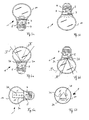
- LED lamp 1 in the FIG. 1 in lateral view and in FIG. 2 schematically illustrated LED lamp 1 according to the invention is designed as a retrofit lamp, that is provided for connection to conventional mains power.
- the lamp 1 initially has a socket 4 for screwing into conventional mains current receptacles.
- the socket 4 would be replaced by corresponding pin contacts.
- an LED chip 3 is arranged on a carrier 2, wherein the carrier 2 is a corresponding substrate, which consists for example of silicon or a silicon compound.
- the LED lamp 1 also has electronics, the components of which are arranged below the carrier 2.
- This electronics includes In particular, a driver circuit 5 for driving the LED 3.
- the driver circuit 5 is designed to reduce the mains voltage U 0, for example, 220 volts or 110 volts to a suitable for operation of the light emitting diode 3 voltage.
- the AC supply current is converted into a DC voltage which, for example, can be PWM-modulated in order to set the brightness of the LED 3.
- This measure known from the prior art has proven to be particularly efficient for dimming LEDs.
- the light emitting diode 3 may also be associated with a corresponding optics for influencing the light output, which is formed in the illustrated embodiment by a conically widening of the light emitting diode 3 reflector 6.
- LED lamp 1 the structure of classic retrofit LED bulbs.
- a special feature of the LED lamp 1 according to the invention is now that it additionally has an integrated sensor 7 for detecting the installation position of the lamp 1.
- the task of this sensor 7 is to detect the orientation or orientation of the lamp 1 and to provide appropriate information to the control electronics or driver circuit 5.
- Such sensors are known and can be realized for example by mercury switch or arrangements consisting of a ball with a corresponding arrangement of microswitches.
- the sensor 7 is able to detect whether the lamp 1 is oriented upwards, downwards or laterally.
- the lamp 1 according to the invention also differs from solutions, as they are known, for example, floor lamps forth, in which the floor lamp includes a sensor that detects a tilting of the lamp and then disables the light mode.
- an adapted operation takes place depending on the detected position and the sensor information is available internally and is not made available by an external means.
- FIGS. 3a and 3b illustrated embodiment it is assumed that in fact only a single light-emitting diode 3 is used, as in the case of Figures 1 and 2 the case was. It is in FIG. 3a an installation of the lamp 1 provided in an upward orientation, whereas in the variant according to FIG. 3b the lamp 1 is directed towards the bottom. Both installation situations differ in that the heat occurring during operation of the light-emitting diode 3 at the in FIG. 3a shown orientation of the lamp 1 is better dissipated than in an arrangement according to FIG. 3b , The reason for this is that in the case where the lamp 1 faces upward, the heat is released more efficiently across the transparent body 10 of the lamp 1, while in the case of FIG. 3b the rising heat may result in additional thermal stress on the electronics located near the socket 4.
- the orientation of the lamp 1 detected by the sensor 7 and the corresponding information of the driver circuit 5 is provided.
- the power in a mounting position according to FIG. 3b can then be ensured that even in this case, a permanent operation of the LED lamp 1 leads to no thermal overload of the electronics.
- the lamp has two light emitting diodes or two groups of light emitting diodes 3a and 3b, which are associated with different optics.
- These optics which are located in the immediate vicinity of the corresponding light-emitting diodes 3a, 3b and are formed by lenses and / or reflectors, are usually provided to radiate the light emitted by the associated LED, as a rule, in a very large angular range over a smaller angular range restrict, wherein in the present embodiment, the optics or optics of the first light-emitting diode (s) 3a effect radiation in a larger space area I, whereas the space region II of the optics (n) of the second light emitting diode (s) 3b is dimensioned narrower.
- a light output by the LED lamp 1 takes place in a larger
- the orientation of the lamp 1 detected by the sensor 7 is interpreted by the driver circuit 5 in such a way that, in an orientation according to FIG. 4a the lamp is upwards, so for example directed against a ceiling of a room to be illuminated, while in an orientation according to FIG. 4b the lamp 1 is directed downwards and thus provided for direct lighting.
- a more concentrated light output is advantageous for a corresponding direct illumination, whereas, in the case of an indirect illumination according to FIG. 4a a light output in a larger angular range is desired.
- the first LED 3a with the larger angular distribution is activated or operated at least with a higher intensity than the second LED 3b, while the intensities in the alignment towards the bottom according to FIG. 4b be reversed.
- the lamp 1 thus recognizes independently whether it is used for direct or indirect lighting and accordingly adjusts the light output for this purpose.
- FIGS. 5a and 5b A third application example of the invention is in the FIGS. 5a and 5b shown, in which case now several LEDs 3a, 3b and 3c are used, which are arranged on differently oriented carriers.
- the lamp 1 which in Fig. 5b from the front, installed in a horizontal position, which is usually the case when the light emitted by the lamp emitted to both the top and to the bottom to achieve a combined direct / indirect lighting.
- the lamp 1 automatically adjusts the light output with regard to the spatial distribution.
- the driver circuit 5 has a correspondingly stored information available, according to which scheme the LEDs to be operated are to be controlled as a function of the installation position detected by the sensor 7.
- the lamp 1 an interface 20 (see FIG. 2 ), which enables the external supply of appropriate information.
- This interface can be designed to be connected to an external programming device, for example a PC 25, as in FIG FIG. 2 is indicated.
- a wireless transmission would be conceivable.
Description
Die vorliegende Erfindung betrifft eine LED-Lampe mit einer oder mehreren Leuchtdioden als Lichtquelle. Insbesondere betrifft die vorliegende Erfindung eine so genannte Retrofit-LED-Lampe, welche als Ersatz für klassische Halogenlampen oder Glühlampen vorgesehen ist, sowie ein Verfahren zum Betreiben einer derartigen Lampe.The present invention relates to an LED lamp with one or more LEDs as a light source. In particular, the present invention relates to a so-called retrofit LED lamp, which is intended as a replacement for classic halogen lamps or incandescent lamps, and a method for operating such a lamp.
Die Weiterentwicklung klassischer Leuchtdioden auf Halbleiterbasis oder so genannter organischer Leuchtdioden, OLEDs, hat dazu geführt, dass derartige Lichtquellen immer häufiger zu Beleuchtungszwecken eingesetzt werden. Leuchtdioden zeichnen sich im Vergleich zu klassischen Lichtquellen wie Glühlampen oder Leuchtstofflampen durch ihre hohe Lichteffizienz und ihre Langlebigkeit aus. Des Weiteren handelt es sich in der Regel um Lichtquellen mit äußerst geringen Abmessungen, was einen sehr flexiblen Einsatz ermöglicht. Ein weiterer Vorteil dieser Lichtquellen besteht schließlich darin, dass diese verhältnismäßig einfach in ihrer Helligkeit verändert, also gedimmt werden können. Dies erlaubt es, mittels mehrfarbiger LED-Module beliebige Mischfarben oder Farbtemperaturen zu erzeugen. Eine Veränderung der Helligkeit der einzelnen LEDs erfolgt dabei in der Regel über eine PWM-Ansteuerung mit Hilfe einer entsprechenden Treiberschaltung.The further development of conventional light-emitting diodes based on semiconductors or so-called organic light-emitting diodes, OLEDs, has led to such light sources being used more and more frequently for illumination purposes. Light-emitting diodes are distinguished by their high light efficiency and longevity compared to conventional light sources such as incandescent lamps or fluorescent lamps. Furthermore, these are generally light sources with extremely small dimensions, which allows a very flexible use. Finally, another advantage of these light sources is that they can be relatively easily changed in their brightness, that is dimmed. This makes it possible to produce any mixed colors or color temperatures by means of multicolored LED modules. A change in the brightness of the individual LEDs is generally carried out via a PWM control with the aid of a corresponding driver circuit.
Ein besonderes Anwendungsgebiet derartiger Lichtquellen besteht in so genannten Retrofit-LED-Lampen. Es handelt sich hierbei um Lampen mit einer oder mehreren Leuchtdioden als Lichtquellen, wobei die LED-Lampe die Form und Funktion beispielsweise einer konventionellen Glühbirne aufweist. Dies bedeutet insbesondere, dass die Lampe mit einem Sockel versehen ist, der das Einschrauben in herkömmliche Glühlampen-Fassungen ermöglicht. Intern ist dann eine entsprechende Elektronik, insbesondere eine Treiberschaltung vorgesehen, welche die allgemeine Netzspannung in einen geeigneten Versorgungsstrom zum Betreiben der Leuchtdioden umsetzt. Auch hinsichtlich ihrer weiteren Form entsprechen derartige Retrofit-LED-Lampen klassischen Glühbirnen, d.h., sie weisen einen transparenten oder transluzenten Hohlkörper in Birnenform auf, in dem die Leuchtdioden angeordnet sind. Mit derartigen Retrofitlampen können allerdings nicht nur konventionelle Glühbirnen sondern beispielsweise auch Halogenlampen oder dergleichen ersetzt werden.A particular field of application of such light sources consists in so-called retrofit LED lamps. These are lamps with one or more light-emitting diodes as light sources, the LED lamp having the form and function of, for example, a conventional light bulb. This means in particular that the lamp is provided with a base which allows screwing into conventional incandescent lamp sockets. Internally, a corresponding electronics, in particular a driver circuit is provided, which converts the general mains voltage into a suitable supply current for operating the light-emitting diodes. Also in terms of their further form, retrofit LED lamps of this type correspond to conventional light bulbs, that is to say they have a transparent or translucent hollow body in the shape of a bulb, in which the light-emitting diodes are arranged. With such retrofit lamps, however, not only conventional light bulbs but also, for example, halogen lamps or the like can be replaced.
Eine Besonderheit derartiger Retrofit-LED-Lampen besteht darin, dass die als Lichtquellen dienenden Leuchtdioden üblicherweise auf einer Platine angeordnet sind und dementsprechend Licht primär in einen bestimmten Raumbereich abstrahlen, im Gegensatz zu dem Glühdraht einer klassischen Glühbirne, über den - abgesehen von dem Sockelbereich der Glühbirne - eine allumfängliche Lichtabstrahlung erzielt wird. Zwar kann auch bei Retrofit-LED-Lampen mit Hilfe entsprechender Optiken und/oder einer Vielzahl von unterschiedlich ausgerichteten Leuchtdioden eine vollumfängliche Lichtabstrahlung erzielt werden, in manchen Fällen ist dies allerdings gar nicht sinnvoll bzw. gar nicht gewünscht.A special feature of such retrofit LED lamps is that the LEDs serving as light sources are usually arranged on a circuit board and accordingly emit light primarily in a certain area of space, in contrast to the filament of a conventional light bulb, over which - except for the base region of the bulb - an allumfängliche light radiation is achieved. Although full retroreflective radiation can also be achieved with retrofit LED lamps with the aid of appropriate optics and / or a multiplicity of differently oriented light-emitting diodes, in some cases this is not at all expedient or even desired.
Die
Der vorliegenden Erfindung liegt deshalb die Aufgabenstellung zugrunde, bei LED-Lampen der zuvor beschriebenen Art die Ansteuerung der Lichtquellen zu optimieren.The present invention is therefore the task of optimizing the control of the light sources in LED lamps of the type described above.
Die Aufgabe wird durch eine LED-Lampe, welche die Merkmale des Anspruchs 1 aufweist, sowie durch ein Verfahren gemäß Anspruch 9 gelöst. Vorteilhafte Weiterbildungen der Erfindung sind Gegenstand der abhängigen Ansprüche.The object is achieved by an LED lamp having the features of claim 1, and by a method according to claim 9. Advantageous developments of the invention are the subject of the dependent claims.
Erfindungsgemäß wird dementsprechend eine LED-Lampe, insbesondere eine Retrofit-LED-Lampe vorgeschlagen, welche mindestens eine Leuchtdiode sowie eine Treiberschaltung zur Stromversorgung der Leuchtdiode aufweist, wobei die LED-Lampe ferner Mittel zum Erfassen der Ausrichtung bzw. Orientierung der LED-Lampe aufweist und die Treiberschaltung dazu ausgebildet ist, die Leuchtdiode abhängig von der erfassten Ausrichtung bzw. Orientierung der LED-Lampe zu betreiben.According to the invention an LED lamp, in particular a retrofit LED lamp is proposed accordingly, which has at least one light emitting diode and a driver circuit for powering the light emitting diode, wherein the LED lamp further comprises means for detecting the orientation or orientation of the LED lamp and the driver circuit is designed to operate the light-emitting diode as a function of the detected orientation or orientation of the LED lamp.
Dabei weist die erfindungsgemäße LED-Lampe mehrere Leuchtdioden auf, welche zumindest teilweise verschieden ausgerichtet sind, wobei die Treiberschaltung dann dazu ausgebildet ist, bei dem Betreiben der LEDs deren Ausrichtung bzw. Ausrichtungen zu berücksichtigen. In diesem Fall wird also abhängig von der Lage der LED-Lampe eine unterschiedliche Lichtverteilung erzeugt. Ergänzend oder alternativ hierzu kann auch vorgesehen sein, dass die LED-Lampe mehrere Leuchtdioden aufweist, denen jeweils eine Optik zur Beeinflussung des von der jeweiligen Leuchtdiode emittierten Lichts zugeordnet ist, wobei die Optiken der Leuchtdioden zumindest teilweise unterschiedlich sind und die Treiberschaltung wiederum dazu ausgebildet ist, eine Ansteuerung der Leuchtdioden entsprechend der erfassten Ausrichtung bzw. Orientierung sowie unter Berücksichtigung der Optiken vorzunehmen. Auch in diesem Fall wird also die Lichtverteilung an die erfasste Lage der LED-Lampe angepasst. Dabei sind vorzugsweise mehrere Leuchtdioden jeweils zu Gruppen zusammengefasst, wobei die Leuchtdioden einer Gruppe jeweils parallel zueinander ausgerichtet sind und/oder identische Optiken aufweisen und die Treiberschaltung dazu ausgebildet ist, die Leuchtdioden einer Gruppe einheitlich zu betreiben.In this case, the LED lamp according to the invention has a plurality of light emitting diodes, which are at least partially aligned differently, wherein the driver circuit is then designed to take into account the orientation or alignments in the operation of the LEDs. In this case, therefore, a different light distribution is generated depending on the position of the LED lamp. Additionally or alternatively, it can also be provided that the LED lamp has a plurality of light-emitting diodes, each of which has an optical system for influencing the one of the respective LED light emitted is associated, wherein the optics of the light-emitting diodes are at least partially different and the driver circuit is in turn adapted to carry out a control of the LEDs according to the detected orientation or orientation and taking into account the optics. Also in this case, therefore, the light distribution is adapted to the detected position of the LED lamp. In this case, preferably, a plurality of LEDs are each combined into groups, wherein the LEDs of a group are each aligned parallel to each other and / or have identical optics and the driver circuit is adapted to operate the LEDs of a group uniformly.
Das erfindungsgemäße Konzept ist allerdings nicht auf LED-Lampen beschränkt, bei denen die Leuchtdioden zumindest teilweise unterschiedlich ausgerichtet oder mit unterschiedlichen Optiken versehen sind. Eine lageabhängige Ansteuerung der Leuchtdioden kann auch dann sinnvoll sein, wenn alle Leuchtdioden identisch ausgerichtet und mit identischen Optiken versehen sind. Insbesondere kann hierbei berücksichtigt werden, dass je nach Ausrichtung der LED-Lampe die während des Betriebs der Leuchtdioden erzeugte Wärme unterschiedlich effektiv abgeführt werden kann, was dann von der Treiberschaltung wiederum berücksichtigt wird, um einen dauerhaft zuverlässigen Betrieb der Lampe gewährleisten zu können.However, the inventive concept is not limited to LED lamps, in which the LEDs are at least partially aligned differently or provided with different optics. A position-dependent control of the light emitting diodes may also be useful if all the LEDs are aligned identically and provided with identical lenses. In particular, it can be taken into account here that, depending on the orientation of the LED lamp, the heat generated during the operation of the light emitting diodes can be dissipated at different effective levels, which in turn is taken into account by the driver circuit in order to be able to ensure a permanently reliable operation of the lamp.
Das lageabhängige Betreiben der Leuchtdiode bzw. Leuchtdioden erfolgt dabei mit Hilfe eines vorgegebenen Schemas, welches in der Elektronik der Treiberschaltung hinterlegt ist. Dabei kann gemäß einer vorteilhaften Weiterbildung der Erfindung auch vorgesehen sein, dass dieses Schema modifizierbar bzw. extern vorgebbar ist. In diesem Fall weist die LED-Lampe eine entsprechende Schnittstelle zum Zuführen entsprechender Informationen auf. Es kann sich hierbei um eine separate Schnittstelle zum Anschließen eines geeigneten Programmiergeräts oder zur drahtlosen Übermittlung der Informationen handeln, denkbar wäre insbesondere beim Einsatz von Retrofit-LED-Lampen allerdings auch, die Information mittels der bekannten Powerline-Technologie zu übertragen.The position-dependent operation of the light-emitting diode or light-emitting diodes takes place with the aid of a predetermined scheme which is stored in the electronics of the driver circuit. It can also be provided according to an advantageous development of the invention that this scheme is modifiable or externally predetermined. In this case, the LED lamp has a corresponding interface for supplying corresponding information. This may be a separate interface for connecting a suitable programming device or for the wireless transmission of information, would be conceivable in particular when using retrofit LED lamps, however, also to transmit the information using the known powerline technology.
Nachfolgend soll die Erfindung anhand der beiliegenden Zeichnung näher erläutert werden. Es zeigen:
- Figur 1
- ein Ausführungsbeispiel einer erfindungsgemäßen LED-Lampe in seitlicher Ansicht;
Figur 2- ein Blockschaltbild der wesentlichen Komponenten der erfindungsgemäßen LED-Lampe;
- Figuren 3a und 3b
- eine erste denkbare Variante zur lageabhängigen Ansteuerung der erfindungsgemäßen LED-Lampe;
- Figuren 4a und 4b
- eine zweite Variante zur lageabhängigen Ansteuerung der erfindungsgemäßen LED-Lampe und
- Figuren 5a und 5b
- eine dritte Variante zur lageabhängigen Ansteuerung der erfindungsgemäßen LED-Lampe.
- FIG. 1
- an embodiment of an LED lamp according to the invention in a side view;
- FIG. 2
- a block diagram of the essential components of the LED lamp according to the invention;
- FIGS. 3a and 3b
- a first conceivable variant for position-dependent control of the LED lamp according to the invention;
- FIGS. 4a and 4b
- a second variant for position-dependent control of the LED lamp according to the invention and
- FIGS. 5a and 5b
- a third variant for position-dependent control of the LED lamp according to the invention.
Nachfolgend wird die Erfindung anhand eines bevorzugten Ausführungsbeispiels in Form einer sog. Retrofit-Glühbirne beschrieben. Es sei allerdings darauf hingewiesen, dass das erfindungsgemäße Konzept nicht auf derartige Glühbirnen beschränkt ist sondern generell bei LED-Lampen zum Einsatz kommen kann. Insbesondere wären auch Retrofit-Halogenlampen entsprechend der vorliegenden Erfindung denkbar.The invention will be described with reference to a preferred embodiment in the form of a so-called. Retrofit bulb. It should be noted, however, that the inventive concept is not limited to such bulbs but can generally be used in LED lamps. In particular, retrofit halogen lamps according to the present invention would also be conceivable.
Ferner werden nachfolgend als Lichtquellen der erfindungsgemäßen LED-Lampe in erster Linie Leuchtdioden auf Halbleiterbasis, also klassische LEDs beschrieben. In gleicher Weise könnte allerdings die erfindungsgemäße lageabhängige Ansteuerung auch bei so genannten organischen LEDs (OLEDs) erfolgen.Furthermore, light-emitting diodes based on semiconductors, that is to say conventional LEDs, will be described below as light sources of the LED lamp according to the invention in the first place. In the same way, however, the position-dependent control according to the invention could also take place in so-called organic LEDs (OLEDs).
Die in
Im dargestellten Ausführungsbeispiel ist lediglich eine einzelne Leuchtdiode 3 dargestellt, wie später noch näher erläutert wird, kann allerdings die Anzahl der zum Einsatz kommenden Leuchtdioden auch deutlich größer sein und diese können sich hinsichtlich ihrer Orientierung und/oder zugeordneten optischen Mittel unterscheiden.In the illustrated embodiment, only a single
Die erfindungsgemäße LED-Lampe 1 weist weiterhin eine Elektronik auf, deren Bauteile unterhalb des Trägers 2 angeordnet sind. Diese Elektronik umfasst insbesondere eine Treiberschaltung 5 zum Ansteuern der Leuchtdiode 3. Die Treiberschaltung 5 ist dabei dazu ausgebildet, die Netzspannung U0 von beispielsweise 220 Volt oder 110 Volt auf eine zum Betrieb der Leuchtdiode 3 geeignete Spannung herabzusetzen. Dabei wird - wie im Stand der Technik üblich - vorzugsweise der Versorgungswechselstrom in eine Gleichspannung umgesetzt, welche zur Einstellung der Helligkeit der Leuchtdiode 3 beispielsweise PWM-moduliert sein kann. Diese aus dem Stand der Technik bekannte Maßnahme hat sich als besonders effizient zum Dimmen von LEDs herausgestellt. Der Leuchtdiode 3 kann dabei auch eine entsprechende Optik zur Beeinflussung der Lichtabgabe zugeordnet sein, welche im dargestellten Ausführungsbeispiel durch einen sich von der Leuchtdiode 3 konisch erweiternden Reflektor 6 gebildet ist.The LED lamp 1 according to the invention also has electronics, the components of which are arranged below the
Hinsichtlich des bisher beschriebenen Aufbaus entspricht die in den
Die von dem Sensor 7 zur Verfügung gestellten Informationen werden erfindungsgemäß dann von der Treiberschaltung 5 beim Betreiben der Leuchtdiode 3 berücksichtigt. Es erfolgt also durch die LED-Lampe 1 ein lageabhängiger Betrieb der Leuchtdiode 3, ohne dass der Lampe 1 hierfür extern irgendwelche Informationen zugeführt werden. In dieser Hinsicht unterscheidet sich die erfindungsgemäße Lampe 1 auch von Lösungen, wie sie beispielsweise von Stehleuchten her bekannt sind, bei denen die Stehleuchte einen Sensor beinhaltet, der ein Kippen der Leuchte erkennt und dann den Leuchtenbetrieb deaktiviert. Demgegenüber erfolgt bei der erfindungsgemäßen LED-Lampe 1 abhängig von der erfassten Lage ein angepasster Betrieb (kein reines Ein- und Ausschalten) und die Sensorinformationen stehen intern zur Verfügung und werden nicht von einem externen Mittel zur Verfügung gestellt.The information provided by the
Ein lageabhängiger Betrieb der Leuchtdiode bzw. Leuchtdioden kann nunmehr in unterschiedlicher Weise erfolgen. Anhand der nachfolgend beschriebenen Figuren werden drei denkbare Varianten erläutert, bei denen abhängig von der Orientierung der Lampe 1 der Betrieb entsprechend modifiziert wird. Selbstverständlich ist dieses Konzept allerdings auch auf weitere Situation anwendbar.A position-dependent operation of the light emitting diode or light emitting diodes can now be done in different ways. With reference to the figures described below, three conceivable variants are explained in which, depending on the orientation of the Lamp 1, the operation is modified accordingly. Of course, this concept is also applicable to other situations.
Bei dem in den
Gemäß der vorliegenden Erfindung ist dementsprechend nunmehr vorgesehen, dass die Ausrichtung der Lampe 1 durch den Sensor 7 erkannt und die entsprechende Information der Treiberschaltung 5 zur Verfügung gestellt wird. Diese berücksichtigt nunmehr die erfasste Einbaulage der Lampe 1 und betreibt beispielsweise bei der Ausrichtung gemäß
Das in dem Ausführungsbeispiel gemäß der
Ferner besteht eine entsprechende Möglichkeit zur Ansteuerung gemäß dem in den
Eine zweite denkbare Möglichkeit zur lageabhängigen Ansteuerung ist in den
Bei dem in den
Gemäß dem Ausführungsbeispiel ist dementsprechend vorgesehen, dass bei einer Orientierung entsprechend
Ein drittes Anwendungsbeispiel der Erfindung ist in den
Es ist offensichtlich, dass die anhand der Figuren beschriebenen drei verschiedenen Ausführungsbeispiele in vielfältiger Weise variiert oder kombiniert werden können. Insbesondere wäre auch eine Kombination der beiden Beispiele der
Dabei wäre es denkbar, dass die entsprechenden Regeln zum Ansteuern der Leuchtdioden werksseitig einprogrammiert werden, allerdings alternativ oder ergänzend hierzu durch den späteren Benutzer auch modifiziert werden können. Gemäß einer vorteilhaften Weiterbildung der Erfindung kann dementsprechend die Lampe 1 eine Schnittstelle 20 (siehe
Letztendlich gestattet allerdings die erfindungsgemäße Lösung, dass der Betrieb der Leuchtdioden effektiv an die Einbaulage der LED-Lampe angepasst wird, wodurch der Betrieb der Lampe aber auch die von der Lampe erzeugte Lichtabgabe optimiert wird.Ultimately, however, allows the solution according to the invention that the operation of the light emitting diodes is effectively adapted to the mounting position of the LED lamp, whereby the operation of the lamp but also the light output generated by the lamp is optimized.
Claims (13)
- Retrofit LED lamp (1) with at least one light-emitting diode (LED, 3) as well as a driver circuit (5) for supplying the light-emitting diode (3) with power, wherein the retrofit LED lamp (1) further has means (7) for determining the alignment or orientation of the retrofit LED lamp (1) and the driver circuit (5) is configured to operate the light-emitting diode (3) depending on the determined alignment or orientation of the retrofit LED lamp (1), characterized in that it has several light-emitting diodes (3) which are at least partially aligned differently, wherein the driver circuit (5) is configured to take during operating of the light-emitting diodes (3) the alignment or alignments thereof into consideration.
- Retrofit LED lamp according to claim 1, characterized in that the driver circuit (5) is configured to influence the spatial light emission depending on the alignment or orientation of the retrofit LED lamp (1).
- Retrofit LED lamp according to claim 2, characterized in that it has several light-emitting diodes (3) to which one optical system is assigned, respectively, for influencing the light emitted by the respective light-emitting diode (3), wherein the optical systems are at least partially different and the driver circuit (5) is configured to take during the operating of the light-emitting diodes (3) the optical systems thereof into consideration.
- Retrofit LED lamp according to claim 2 or 3, characterized in that the several light-emitting diodes (3) are combined to groups, respectively, wherein the light-emitting diodes (3) of a group are respectively aligned parallel to one another and/or have identical optical systems, and the driver circuit (5) is configured to uniformly operate the light-emitting diodes (3) of a group.
- Retrofit LED lamp according to one of the preceding claims, characterized in that the driver circuit (5) is configured to adjust the intensity of the light emission or the maximum allowable intensity in a dimming operation depending on the alignment or orientation of the retrofit LED lamp (1).
- Retrofit LED lamp according to one of the preceding claims, characterized in that the driver circuit (5) operates the light-emitting diode (3) or light-emitting diodes according to a preset scheme.
- Retrofit LED lamp according to claim 6, characterized in that it has an interface (20) for transmitting an externally given actuating scheme for the driver circuit (5).
- Retrofit LED lamp according to one of the preceding claims, characterized in that the light-emitting diodes (3) are formed by LEDs or OLEDs.
- Method for operating a retrofit LED lamp (1) with at least one light-emitting diode (LED, 3), wherein the alignment or orientation of the retrofit LED lamp (1) is determined and the light-emitting diode (3) is operated depending on the determined alignment or orientation of the retrofit LED lamp (1), characterized in that the retrofit LED lamp (1) has several light-emitting diodes (3), wherein the alignment or alignments are being taken into consideration during the operation of the light-emitting diodes (3).
- Method according to claim 10, characterized in that the spatial light emission is influenced depending on the alignment or orientation of the retrofit LED lamp (1).
- Method according to claim 10, characterized in that the retrofit LED lamp (1) has several light-emitting diodes (3) to which an optical system is assigned, respectively, for influencing the light emitted by the respective light-emitting diode (3), wherein the optical systems are at least partially different, and during the operation of the light-emitting diodes (3) the optical systems thereof are taken into consideration.
- Method according to claim 10 or 11, characterized in that the several light-emitting diodes (3) are combined into groups, respectively, wherein the light-emitting diodes (3) of a group are aligned, respectively, parallel to one another and/or have identical optical systems and the light-emitting diodes (3) of a group are operated uniformly.
- Method according to one of the claims 9 to 12, characterized in that the intensity of the light emission or the maximum allowed intensity in a dimming operation is adjusted depending on the alignment or orientation of the retrofit LED lamp (1).
Applications Claiming Priority (1)
| Application Number | Priority Date | Filing Date | Title |
|---|---|---|---|
| DE102012203748A DE102012203748A1 (en) | 2012-03-09 | 2012-03-09 | LED lamp and method of operating such a lamp |
Publications (2)
| Publication Number | Publication Date |
|---|---|
| EP2636948A1 EP2636948A1 (en) | 2013-09-11 |
| EP2636948B1 true EP2636948B1 (en) | 2016-09-07 |
Family
ID=47827077
Family Applications (1)
| Application Number | Title | Priority Date | Filing Date |
|---|---|---|---|
| EP13158328.8A Not-in-force EP2636948B1 (en) | 2012-03-09 | 2013-03-08 | LED lamp and method for operating such a lamp |
Country Status (2)
| Country | Link |
|---|---|
| EP (1) | EP2636948B1 (en) |
| DE (1) | DE102012203748A1 (en) |
Families Citing this family (2)
| Publication number | Priority date | Publication date | Assignee | Title |
|---|---|---|---|---|
| IT201700070288A1 (en) * | 2017-06-23 | 2018-12-23 | Redox S R L | High efficiency LED lamp |
| WO2019016079A1 (en) | 2017-07-20 | 2019-01-24 | Philips Lighting Holding B.V. | Lighting module |
Family Cites Families (9)
| Publication number | Priority date | Publication date | Assignee | Title |
|---|---|---|---|---|
| US6030099A (en) * | 1998-06-16 | 2000-02-29 | Mcdermott; Kevin | Selected direction lighting device |
| GB2377986A (en) * | 2001-07-16 | 2003-01-29 | Mathmos Ltd | Lighting apparatus responsive to spatial orientation |
| CN101392899B (en) * | 2007-09-21 | 2012-01-11 | 富士迈半导体精密工业(上海)有限公司 | LED lamp with heat radiation structure |
| EP2154419B1 (en) * | 2008-07-31 | 2016-07-06 | Toshiba Lighting & Technology Corporation | Self-ballasted lamp |
| DE102009010180A1 (en) * | 2009-02-23 | 2010-10-28 | Osram Gesellschaft mit beschränkter Haftung | Lighting device with at least one semiconductor light source |
| EP2417388B1 (en) * | 2009-04-09 | 2016-02-10 | Tridonic Jennersdorf GmbH | Integrated led and sensor device |
| WO2010150207A1 (en) * | 2009-06-25 | 2010-12-29 | Koninklijke Philips Electronics N.V. | Floating lamp |
| US8596821B2 (en) * | 2010-06-08 | 2013-12-03 | Cree, Inc. | LED light bulbs |
| US8827504B2 (en) * | 2010-06-18 | 2014-09-09 | Rambus Delaware Llc | Light bulb using solid-state light sources |
-
2012
- 2012-03-09 DE DE102012203748A patent/DE102012203748A1/en not_active Withdrawn
-
2013
- 2013-03-08 EP EP13158328.8A patent/EP2636948B1/en not_active Not-in-force
Also Published As
| Publication number | Publication date |
|---|---|
| EP2636948A1 (en) | 2013-09-11 |
| DE102012203748A1 (en) | 2013-09-12 |
Similar Documents
| Publication | Publication Date | Title |
|---|---|---|
| EP2417388B1 (en) | Integrated led and sensor device | |
| WO2016071371A1 (en) | Surgical light and method for operating a surgical light | |
| EP2499426B1 (en) | System comprising a base carrier and a light source carrier | |
| WO2015058940A1 (en) | Lighting device for a motor vehicle, comprising a multifunctional luminaire | |
| EP1871145B1 (en) | Illumination system | |
| DE202010017320U1 (en) | Floor or table lamp | |
| DE102011076128A1 (en) | Support system for light module e.g. LED module used in office, has light module that is mounted over support portion and contact with electric wires of support portion | |
| DE112009001774B4 (en) | Light source with LED, emergency route lighting and method for evenly illuminating an area | |
| EP2636948B1 (en) | LED lamp and method for operating such a lamp | |
| DE102010043013B4 (en) | Lighting device and method for lighting | |
| DE102014019475A1 (en) | Lighting device for a traffic signal system of rail-bound traffic | |
| DE102008017271B4 (en) | Luminaire with two light sources in a recess of an at least partially photoconductive support, use of this lamp as a pendant, wall or floor lamp and lighting device for such a lamp | |
| DE102016120256A1 (en) | LIGHTING DEVICE WITH VARIABLE LIGHT DISTRIBUTION | |
| EP2367401A2 (en) | Device with an illumination device and method for its control | |
| WO2010015277A1 (en) | Multi-led lighting device | |
| DE102007009229A1 (en) | Light source for illuminant for illuminant arrangement, has multiple carrier element plates, each carrier element plate is flat surface section on which light emitting diode is arranged | |
| DE19919080A1 (en) | Lighting device for illuminating surfaces and spaces incorporates light-emitting semiconductor elements acting as sources of light supplied with a power source and controlled by electronic components. | |
| DE112013002008T5 (en) | Illumination light source | |
| EP3081855B1 (en) | Spotlight | |
| DE202016107013U1 (en) | Lighting unit, in particular for a screen lamp, and lamp, in particular screen lamp, with a lighting unit | |
| EP2566300B1 (en) | LED Module sytem | |
| EP2360420B1 (en) | Modular lamp system for light emitting diodes | |
| EP4074591A2 (en) | Light unit for mounting in a marine headlight | |
| WO2019081506A1 (en) | Led module with changeable emission characteristic | |
| EP2415043A1 (en) | Lamp, preferably for illuminating advertising |
Legal Events
| Date | Code | Title | Description |
|---|---|---|---|
| PUAI | Public reference made under article 153(3) epc to a published international application that has entered the european phase |
Free format text: ORIGINAL CODE: 0009012 |
|
| AK | Designated contracting states |
Kind code of ref document: A1 Designated state(s): AL AT BE BG CH CY CZ DE DK EE ES FI FR GB GR HR HU IE IS IT LI LT LU LV MC MK MT NL NO PL PT RO RS SE SI SK SM TR |
|
| AX | Request for extension of the european patent |
Extension state: BA ME |
|
| 17P | Request for examination filed |
Effective date: 20140127 |
|
| RBV | Designated contracting states (corrected) |
Designated state(s): AL AT BE BG CH CY CZ DE DK EE ES FI FR GB GR HR HU IE IS IT LI LT LU LV MC MK MT NL NO PL PT RO RS SE SI SK SM TR |
|
| 17Q | First examination report despatched |
Effective date: 20151111 |
|
| RIC1 | Information provided on ipc code assigned before grant |
Ipc: F21K 99/00 20160101ALI20160314BHEP Ipc: F21V 23/04 20060101AFI20160314BHEP Ipc: F21Y 115/10 20160101ALN20160314BHEP |
|
| GRAP | Despatch of communication of intention to grant a patent |
Free format text: ORIGINAL CODE: EPIDOSNIGR1 |
|
| RIC1 | Information provided on ipc code assigned before grant |
Ipc: F21Y 115/10 20160101ALN20160331BHEP Ipc: F21K 9/232 20160101ALI20160331BHEP Ipc: F21V 23/04 20060101AFI20160331BHEP |
|
| INTG | Intention to grant announced |
Effective date: 20160503 |
|
| GRAS | Grant fee paid |
Free format text: ORIGINAL CODE: EPIDOSNIGR3 |
|
| GRAA | (expected) grant |
Free format text: ORIGINAL CODE: 0009210 |
|
| AK | Designated contracting states |
Kind code of ref document: B1 Designated state(s): AL AT BE BG CH CY CZ DE DK EE ES FI FR GB GR HR HU IE IS IT LI LT LU LV MC MK MT NL NO PL PT RO RS SE SI SK SM TR |
|
| REG | Reference to a national code |
Ref country code: GB Ref legal event code: FG4D Free format text: NOT ENGLISH |
|
| REG | Reference to a national code |
Ref country code: CH Ref legal event code: EP |
|
| REG | Reference to a national code |
Ref country code: CH Ref legal event code: NV Representative=s name: WEINMANN ZIMMERLI, CH |
|
| REG | Reference to a national code |
Ref country code: IE Ref legal event code: FG4D Free format text: LANGUAGE OF EP DOCUMENT: GERMAN |
|
| REG | Reference to a national code |
Ref country code: AT Ref legal event code: REF Ref document number: 827217 Country of ref document: AT Kind code of ref document: T Effective date: 20161015 |
|
| REG | Reference to a national code |
Ref country code: DE Ref legal event code: R096 Ref document number: 502013004325 Country of ref document: DE |
|
| REG | Reference to a national code |
Ref country code: LT Ref legal event code: MG4D |
|
| REG | Reference to a national code |
Ref country code: NL Ref legal event code: MP Effective date: 20160907 |
|
| PG25 | Lapsed in a contracting state [announced via postgrant information from national office to epo] |
Ref country code: FI Free format text: LAPSE BECAUSE OF FAILURE TO SUBMIT A TRANSLATION OF THE DESCRIPTION OR TO PAY THE FEE WITHIN THE PRESCRIBED TIME-LIMIT Effective date: 20160907 Ref country code: LT Free format text: LAPSE BECAUSE OF FAILURE TO SUBMIT A TRANSLATION OF THE DESCRIPTION OR TO PAY THE FEE WITHIN THE PRESCRIBED TIME-LIMIT Effective date: 20160907 Ref country code: RS Free format text: LAPSE BECAUSE OF FAILURE TO SUBMIT A TRANSLATION OF THE DESCRIPTION OR TO PAY THE FEE WITHIN THE PRESCRIBED TIME-LIMIT Effective date: 20160907 Ref country code: HR Free format text: LAPSE BECAUSE OF FAILURE TO SUBMIT A TRANSLATION OF THE DESCRIPTION OR TO PAY THE FEE WITHIN THE PRESCRIBED TIME-LIMIT Effective date: 20160907 Ref country code: NO Free format text: LAPSE BECAUSE OF FAILURE TO SUBMIT A TRANSLATION OF THE DESCRIPTION OR TO PAY THE FEE WITHIN THE PRESCRIBED TIME-LIMIT Effective date: 20161207 |
|
| PG25 | Lapsed in a contracting state [announced via postgrant information from national office to epo] |
Ref country code: ES Free format text: LAPSE BECAUSE OF FAILURE TO SUBMIT A TRANSLATION OF THE DESCRIPTION OR TO PAY THE FEE WITHIN THE PRESCRIBED TIME-LIMIT Effective date: 20160907 Ref country code: SE Free format text: LAPSE BECAUSE OF FAILURE TO SUBMIT A TRANSLATION OF THE DESCRIPTION OR TO PAY THE FEE WITHIN THE PRESCRIBED TIME-LIMIT Effective date: 20160907 Ref country code: LV Free format text: LAPSE BECAUSE OF FAILURE TO SUBMIT A TRANSLATION OF THE DESCRIPTION OR TO PAY THE FEE WITHIN THE PRESCRIBED TIME-LIMIT Effective date: 20160907 Ref country code: NL Free format text: LAPSE BECAUSE OF FAILURE TO SUBMIT A TRANSLATION OF THE DESCRIPTION OR TO PAY THE FEE WITHIN THE PRESCRIBED TIME-LIMIT Effective date: 20160907 Ref country code: GR Free format text: LAPSE BECAUSE OF FAILURE TO SUBMIT A TRANSLATION OF THE DESCRIPTION OR TO PAY THE FEE WITHIN THE PRESCRIBED TIME-LIMIT Effective date: 20161208 |
|
| REG | Reference to a national code |
Ref country code: FR Ref legal event code: PLFP Year of fee payment: 5 |
|
| PG25 | Lapsed in a contracting state [announced via postgrant information from national office to epo] |
Ref country code: RO Free format text: LAPSE BECAUSE OF FAILURE TO SUBMIT A TRANSLATION OF THE DESCRIPTION OR TO PAY THE FEE WITHIN THE PRESCRIBED TIME-LIMIT Effective date: 20160907 Ref country code: EE Free format text: LAPSE BECAUSE OF FAILURE TO SUBMIT A TRANSLATION OF THE DESCRIPTION OR TO PAY THE FEE WITHIN THE PRESCRIBED TIME-LIMIT Effective date: 20160907 |
|
| PG25 | Lapsed in a contracting state [announced via postgrant information from national office to epo] |
Ref country code: PT Free format text: LAPSE BECAUSE OF FAILURE TO SUBMIT A TRANSLATION OF THE DESCRIPTION OR TO PAY THE FEE WITHIN THE PRESCRIBED TIME-LIMIT Effective date: 20170109 Ref country code: PL Free format text: LAPSE BECAUSE OF FAILURE TO SUBMIT A TRANSLATION OF THE DESCRIPTION OR TO PAY THE FEE WITHIN THE PRESCRIBED TIME-LIMIT Effective date: 20160907 Ref country code: IS Free format text: LAPSE BECAUSE OF FAILURE TO SUBMIT A TRANSLATION OF THE DESCRIPTION OR TO PAY THE FEE WITHIN THE PRESCRIBED TIME-LIMIT Effective date: 20170107 Ref country code: BG Free format text: LAPSE BECAUSE OF FAILURE TO SUBMIT A TRANSLATION OF THE DESCRIPTION OR TO PAY THE FEE WITHIN THE PRESCRIBED TIME-LIMIT Effective date: 20161207 Ref country code: SM Free format text: LAPSE BECAUSE OF FAILURE TO SUBMIT A TRANSLATION OF THE DESCRIPTION OR TO PAY THE FEE WITHIN THE PRESCRIBED TIME-LIMIT Effective date: 20160907 Ref country code: CZ Free format text: LAPSE BECAUSE OF FAILURE TO SUBMIT A TRANSLATION OF THE DESCRIPTION OR TO PAY THE FEE WITHIN THE PRESCRIBED TIME-LIMIT Effective date: 20160907 Ref country code: SK Free format text: LAPSE BECAUSE OF FAILURE TO SUBMIT A TRANSLATION OF THE DESCRIPTION OR TO PAY THE FEE WITHIN THE PRESCRIBED TIME-LIMIT Effective date: 20160907 |
|
| REG | Reference to a national code |
Ref country code: DE Ref legal event code: R097 Ref document number: 502013004325 Country of ref document: DE |
|
| PG25 | Lapsed in a contracting state [announced via postgrant information from national office to epo] |
Ref country code: IT Free format text: LAPSE BECAUSE OF FAILURE TO SUBMIT A TRANSLATION OF THE DESCRIPTION OR TO PAY THE FEE WITHIN THE PRESCRIBED TIME-LIMIT Effective date: 20160907 |
|
| PLBE | No opposition filed within time limit |
Free format text: ORIGINAL CODE: 0009261 |
|
| STAA | Information on the status of an ep patent application or granted ep patent |
Free format text: STATUS: NO OPPOSITION FILED WITHIN TIME LIMIT |
|
| PG25 | Lapsed in a contracting state [announced via postgrant information from national office to epo] |
Ref country code: DK Free format text: LAPSE BECAUSE OF FAILURE TO SUBMIT A TRANSLATION OF THE DESCRIPTION OR TO PAY THE FEE WITHIN THE PRESCRIBED TIME-LIMIT Effective date: 20160907 |
|
| 26N | No opposition filed |
Effective date: 20170608 |
|
| PG25 | Lapsed in a contracting state [announced via postgrant information from national office to epo] |
Ref country code: SI Free format text: LAPSE BECAUSE OF FAILURE TO SUBMIT A TRANSLATION OF THE DESCRIPTION OR TO PAY THE FEE WITHIN THE PRESCRIBED TIME-LIMIT Effective date: 20160907 |
|
| PG25 | Lapsed in a contracting state [announced via postgrant information from national office to epo] |
Ref country code: MC Free format text: LAPSE BECAUSE OF FAILURE TO SUBMIT A TRANSLATION OF THE DESCRIPTION OR TO PAY THE FEE WITHIN THE PRESCRIBED TIME-LIMIT Effective date: 20160907 |
|
| REG | Reference to a national code |
Ref country code: IE Ref legal event code: MM4A |
|
| PG25 | Lapsed in a contracting state [announced via postgrant information from national office to epo] |
Ref country code: LU Free format text: LAPSE BECAUSE OF NON-PAYMENT OF DUE FEES Effective date: 20170308 |
|
| PG25 | Lapsed in a contracting state [announced via postgrant information from national office to epo] |
Ref country code: IE Free format text: LAPSE BECAUSE OF NON-PAYMENT OF DUE FEES Effective date: 20170308 |
|
| REG | Reference to a national code |
Ref country code: BE Ref legal event code: MM Effective date: 20170331 |
|
| REG | Reference to a national code |
Ref country code: FR Ref legal event code: PLFP Year of fee payment: 6 |
|
| PG25 | Lapsed in a contracting state [announced via postgrant information from national office to epo] |
Ref country code: BE Free format text: LAPSE BECAUSE OF NON-PAYMENT OF DUE FEES Effective date: 20170331 |
|
| PGFP | Annual fee paid to national office [announced via postgrant information from national office to epo] |
Ref country code: AT Payment date: 20180328 Year of fee payment: 6 |
|
| PG25 | Lapsed in a contracting state [announced via postgrant information from national office to epo] |
Ref country code: MT Free format text: LAPSE BECAUSE OF FAILURE TO SUBMIT A TRANSLATION OF THE DESCRIPTION OR TO PAY THE FEE WITHIN THE PRESCRIBED TIME-LIMIT Effective date: 20160907 |
|
| PG25 | Lapsed in a contracting state [announced via postgrant information from national office to epo] |
Ref country code: AL Free format text: LAPSE BECAUSE OF FAILURE TO SUBMIT A TRANSLATION OF THE DESCRIPTION OR TO PAY THE FEE WITHIN THE PRESCRIBED TIME-LIMIT Effective date: 20160907 |
|
| REG | Reference to a national code |
Ref country code: DE Ref legal event code: R084 Ref document number: 502013004325 Country of ref document: DE |
|
| PG25 | Lapsed in a contracting state [announced via postgrant information from national office to epo] |
Ref country code: HU Free format text: LAPSE BECAUSE OF FAILURE TO SUBMIT A TRANSLATION OF THE DESCRIPTION OR TO PAY THE FEE WITHIN THE PRESCRIBED TIME-LIMIT; INVALID AB INITIO Effective date: 20130308 |
|
| PG25 | Lapsed in a contracting state [announced via postgrant information from national office to epo] |
Ref country code: CY Free format text: LAPSE BECAUSE OF NON-PAYMENT OF DUE FEES Effective date: 20160907 |
|
| REG | Reference to a national code |
Ref country code: AT Ref legal event code: MM01 Ref document number: 827217 Country of ref document: AT Kind code of ref document: T Effective date: 20190308 |
|
| PG25 | Lapsed in a contracting state [announced via postgrant information from national office to epo] |
Ref country code: MK Free format text: LAPSE BECAUSE OF FAILURE TO SUBMIT A TRANSLATION OF THE DESCRIPTION OR TO PAY THE FEE WITHIN THE PRESCRIBED TIME-LIMIT Effective date: 20160907 |
|
| PG25 | Lapsed in a contracting state [announced via postgrant information from national office to epo] |
Ref country code: AT Free format text: LAPSE BECAUSE OF NON-PAYMENT OF DUE FEES Effective date: 20190308 |
|
| PG25 | Lapsed in a contracting state [announced via postgrant information from national office to epo] |
Ref country code: TR Free format text: LAPSE BECAUSE OF FAILURE TO SUBMIT A TRANSLATION OF THE DESCRIPTION OR TO PAY THE FEE WITHIN THE PRESCRIBED TIME-LIMIT Effective date: 20160907 |
|
| PGFP | Annual fee paid to national office [announced via postgrant information from national office to epo] |
Ref country code: FR Payment date: 20200326 Year of fee payment: 8 |
|
| REG | Reference to a national code |
Ref country code: CH Ref legal event code: PL |
|
| PG25 | Lapsed in a contracting state [announced via postgrant information from national office to epo] |
Ref country code: LI Free format text: LAPSE BECAUSE OF NON-PAYMENT OF DUE FEES Effective date: 20200331 Ref country code: CH Free format text: LAPSE BECAUSE OF NON-PAYMENT OF DUE FEES Effective date: 20200331 |
|
| PG25 | Lapsed in a contracting state [announced via postgrant information from national office to epo] |
Ref country code: FR Free format text: LAPSE BECAUSE OF NON-PAYMENT OF DUE FEES Effective date: 20210331 |
|
| PGFP | Annual fee paid to national office [announced via postgrant information from national office to epo] |
Ref country code: GB Payment date: 20220322 Year of fee payment: 10 Ref country code: DE Payment date: 20220329 Year of fee payment: 10 |
|
| REG | Reference to a national code |
Ref country code: DE Ref legal event code: R119 Ref document number: 502013004325 Country of ref document: DE |
|
| GBPC | Gb: european patent ceased through non-payment of renewal fee |
Effective date: 20230308 |
|
| PG25 | Lapsed in a contracting state [announced via postgrant information from national office to epo] |
Ref country code: GB Free format text: LAPSE BECAUSE OF NON-PAYMENT OF DUE FEES Effective date: 20230308 |
|
| PG25 | Lapsed in a contracting state [announced via postgrant information from national office to epo] |
Ref country code: GB Free format text: LAPSE BECAUSE OF NON-PAYMENT OF DUE FEES Effective date: 20230308 Ref country code: DE Free format text: LAPSE BECAUSE OF NON-PAYMENT OF DUE FEES Effective date: 20231003 |