EP2636562A1 - Vehicular instrument-mounting structure - Google Patents
Vehicular instrument-mounting structure Download PDFInfo
- Publication number
- EP2636562A1 EP2636562A1 EP12747327.0A EP12747327A EP2636562A1 EP 2636562 A1 EP2636562 A1 EP 2636562A1 EP 12747327 A EP12747327 A EP 12747327A EP 2636562 A1 EP2636562 A1 EP 2636562A1
- Authority
- EP
- European Patent Office
- Prior art keywords
- control device
- power control
- vehicle
- auxiliary battery
- mounting structure
- Prior art date
- Legal status (The legal status is an assumption and is not a legal conclusion. Google has not performed a legal analysis and makes no representation as to the accuracy of the status listed.)
- Granted
Links
Images



Classifications
-
- B—PERFORMING OPERATIONS; TRANSPORTING
- B62—LAND VEHICLES FOR TRAVELLING OTHERWISE THAN ON RAILS
- B62D—MOTOR VEHICLES; TRAILERS
- B62D21/00—Understructures, i.e. chassis frame on which a vehicle body may be mounted
- B62D21/15—Understructures, i.e. chassis frame on which a vehicle body may be mounted having impact absorbing means, e.g. a frame designed to permanently or temporarily change shape or dimension upon impact with another body
- B62D21/152—Front or rear frames
- B62D21/155—Sub-frames or underguards
-
- B—PERFORMING OPERATIONS; TRANSPORTING
- B60—VEHICLES IN GENERAL
- B60R—VEHICLES, VEHICLE FITTINGS, OR VEHICLE PARTS, NOT OTHERWISE PROVIDED FOR
- B60R16/00—Electric or fluid circuits specially adapted for vehicles and not otherwise provided for; Arrangement of elements of electric or fluid circuits specially adapted for vehicles and not otherwise provided for
- B60R16/02—Electric or fluid circuits specially adapted for vehicles and not otherwise provided for; Arrangement of elements of electric or fluid circuits specially adapted for vehicles and not otherwise provided for electric constitutive elements
- B60R16/04—Arrangement of batteries
-
- B—PERFORMING OPERATIONS; TRANSPORTING
- B60—VEHICLES IN GENERAL
- B60K—ARRANGEMENT OR MOUNTING OF PROPULSION UNITS OR OF TRANSMISSIONS IN VEHICLES; ARRANGEMENT OR MOUNTING OF PLURAL DIVERSE PRIME-MOVERS IN VEHICLES; AUXILIARY DRIVES FOR VEHICLES; INSTRUMENTATION OR DASHBOARDS FOR VEHICLES; ARRANGEMENTS IN CONNECTION WITH COOLING, AIR INTAKE, GAS EXHAUST OR FUEL SUPPLY OF PROPULSION UNITS IN VEHICLES
- B60K1/00—Arrangement or mounting of electrical propulsion units
-
- B—PERFORMING OPERATIONS; TRANSPORTING
- B60—VEHICLES IN GENERAL
- B60Y—INDEXING SCHEME RELATING TO ASPECTS CROSS-CUTTING VEHICLE TECHNOLOGY
- B60Y2200/00—Type of vehicle
- B60Y2200/90—Vehicles comprising electric prime movers
- B60Y2200/92—Hybrid vehicles
-
- B—PERFORMING OPERATIONS; TRANSPORTING
- B60—VEHICLES IN GENERAL
- B60Y—INDEXING SCHEME RELATING TO ASPECTS CROSS-CUTTING VEHICLE TECHNOLOGY
- B60Y2306/00—Other features of vehicle sub-units
- B60Y2306/01—Reducing damages in case of crash, e.g. by improving battery protection
Definitions
- the present invention relates to a vehicular instrument-mounting structure, in which a motor case that stores therein an electric rotating machine for driving a vehicle is disposed in a section formed towards a forward side with respect to a vehicle interior, and a power control device which performs control of the electric rotating machine and an auxiliary battery which supplies electric power to a control section of the power control device are mounted.
- electric vehicles that are driven by a driving force of an electric rotating machine such as a motor generator, hybrid vehicles in which an engine which is an internal combustion engine and an electric rotating machine are used in combination, fuel cell vehicles that driven by electric power generated by a fuel cell, and the like have been known.
- These vehicles include a power control device having a boost converter, an inverter, and so on, that receives electric power supplied from a main battery or a fuel cell and controls electric power to a motor generator (hereinafter also referred to as a "motor").
- the power control device is also referred to as a PCU (power control unit).
- PCU power control unit
- Patent Document 1 discloses technology of fixing, on a transaxle (also referred to as a motor case) which includes a first motor generator forming a twin-shaft, a second motor generator arranged parallel to an axial line of the first motor generator, and a differential gear arranged on a third axial line parallel to the twin-shaft, a power control device that drives the first motor generator and the second motor generator, which is achieved by downsizing the power control device.
- a transaxle also referred to as a motor case
- a second motor generator arranged parallel to an axial line of the first motor generator
- a differential gear arranged on a third axial line parallel to the twin-shaft
- Patent Document 2 discloses a structure having a disengagement mechanism in which, at the time of vehicle collision, due to a load transmitted from an auxiliary battery via a guide surface, which is caused by backward movement of the auxiliary battery with the intrusion of a barrier (obstacle), a relay box moves upward and is separated from a vehicle body. With this mechanism, the battery moves backward smoothly. With such a disengagement structure of the relay box, it is possible to prevent interference between the vehicular instruments and other members that would move as a result of a collision impact and to thereby enhance the impact absorbing effect.
- Patent Document 3 discloses an instrument-mounting structure in which, in order to protect the power control device itself at the time of vehicle collision, the power control device is mounted such that the front end of the power control device is located further toward the vehicle's rear side with respect to the front end of the transaxle and a motor compressor is placed toward the vehicle's rear side with respect to the power control device, and the auxiliary battery is mounted at the same position of the power control device thereby facilitating protection of the auxiliary battery.
- Patent Document 4 discloses an inverter disengagement mechanism which, in order to protect a power control device itself such as an inverter, causes the inverter and an inverter bracket to be disengaged from an inverter tray attached to a front member when an external force is applied to the inverter at the time of collision.
- Patent Document 1 and Patent Document 3 described above disclose technology of fixing the power control device on the transaxle, in a layout in which an auxiliary battery is mounted toward the vehicle's front side with respect to the power control device in relation to other instruments, a corner portion of the auxiliary battery having a relatively high strength partially contacts the power control device to thereby generate a reactive force in a casing of the power control device. When this reactive force exceeds the rigidity of the casing of the power control device, a circuit within the power control device breaks. With such a layout, there are cases in which rapid discharge by using the circuit within the power control device at the time of collision becomes difficult.
- a vehicular instrument-mounting structure in which, in a section formed towards a forward side with respect to a vehicle interior, a motor case that stores therein an electric rotating machine for driving a vehicle is disposed, and a power control device which performs control of the electric rotating machine and an auxiliary battery which supplies electric power to a control section of the power control device are mounted,
- the vehicular instrument-mounting structure including a guide member for guiding the power control device toward the rear side of the vehicle, and a linkage member for coupling the guide member with an upper surface of the motor case, wherein the linkage member releases linkage between the motor case and the guide member when an impact load is applied to the power control device, with the auxiliary battery being disposed toward the front side of the vehicle with respect to the power control device, and supported such that the auxiliary battery pushes the power control device movably toward the rear side of the vehicle while the auxiliary battery is moved toward the rear side of the vehicle due to the impact
- the auxiliary battery is disposed such that a rear-most end portion of the auxiliary battery is located toward the rear side of the vehicle with respect to a front-most end portion of the power control device.
- the auxiliary battery is disposed such that a portion of the auxiliary battery is located toward the lateral side with respect to the power control device.
- a direction of disengagement of the power control device is specified to one direction by the guide member and the linkage member.
- the auxiliary battery is mounted on a vehicular skeleton member that absorbs the impact load by being crushed in a crush direction.
- the motor case is a twin-shaft transaxle having two electrical rotary machines.
- the vehicular instrument-mounting structure With the application of the vehicular instrument-mounting structure according to the present invention, because, while an auxiliary battery is mounted in a space formed toward the forward direction with respect to a transaxle, which is secured by mounting the power control device on the transaxle, a reactive force generated in the power control device by being pushed by the auxiliary battery at the time of collision can be absorbed due to disengagement of the power control device, it is possible to speedily discharge the electric charge of high voltage by using a circuit within the power control device.
- this vehicular instrument-mounting structure can obviate the disadvantages caused by collision even when the auxiliary battery is placed on the forward side with respect to the power control device, there are provided advantages that the degree of freedom is high for the layout of the engine compartment and that, in vehicles of various sizes and types, realization of both mounting of the auxiliary battery within an engine compartment and collision safety can be achieved. There is a further advantage that realization of both cost reduction and collision safety can be achieved.
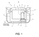
- FIG. 1 illustrates an overview of a vehicular instrument-mounting structure within an engine compartment 20 in a hybrid vehicle 10.
- the engine compartment 20 is located toward the front side of the hybrid vehicle 10 with respect to a passenger compartment.
- the engine compartment 20 includes side members 15 which are vehicular skeleton members of the hybrid vehicle 10, a front cross member 18 for connecting the two side members 15, spring supports 16 connected to the side members 15, an auxiliary battery 14 which is disposed further toward the front side of the vehicle with respect to a PCU 13 and is attached to the front cross member 18 via a support platform 23 and a securing piece 22, a radiator 17 which is attached to the front cross member 18, an engine 11 and a motor case 12 connected to the vehicular skeleton member via an engine mount, an axle 25 extending from the motor case 12, and the PCU 13 connected to the motor case 12 via a guide plate 19 and a linkage bolt.
- side members 15 which are vehicular skeleton members of the hybrid vehicle 10
- a front cross member 18 for connecting the two side members 15, spring supports 16 connected to the side members 15, an auxiliary battery 14 which is disposed further toward the front side of the vehicle with respect to a PCU 13 and is attached to the front cross member 18 via a support platform 23 and a securing piece 22, a radiator
- the PCU 13 includes a boost converter for boosting the voltage of a main battery, an inverter for controlling a boosting coil and a motor generator, and a capacitor for smoothing. Also, a male connector 21 engaging with a female connector of the motor case 12 and a cable connected to the main battery are provided toward the rear side of the vehicle with respect to the PCU 13.
- One of the characteristic features of the present embodiment is to disengageably mount the PCU 13 in a region having a depth formed by a twin-shaft type motor case with the guide plate 19 by using an impact load and to dispose the auxiliary battery 14 toward the front side of the vehicle with respect to the PCU 13. While in the conventional mounting structure a disengagement structure is provided on the vehicular skeleton member such as the front cross member to support the PCU in a disengageable manner, with the disengagement structure being mounted on the PCU 13 as in the present embodiment, it is possible to moderate the restrictions for mounting.
- the PCU 13 itself can absorb the impact load by being disengaged at the time of collision, it is possible to speedily discharge the high voltage electric charge in the inverter and the boost converter of the PCU 13 by using an internal circuit of the PCU 13.
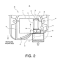
- FIG. 2 is a top view illustrating a deformation of the engine compartment 20 when a barrier intrudes into the hybrid vehicle 10 of FIG. 1 from the vehicle's front side with respect to the engine compartment 20 and right half portion of the vehicle (offset collision).
- offset collision the safety processing for dealing with a collision with a barrier will be described in detail in four separate stages.
- the first stage is a stage of initial collision, in which the barrier comes in contact with the front cross member 18, and the radiator 17 and the auxiliary battery 14 attached to the support platform 23 with the securing piece are pushed into the engine compartment 20 by the barrier.
- the second stage is an impact absorption start stage, in which the front cross member 18 which is squeezed by the barrier transmits the impact load to the side member 15, and the side member 15 and peripheral members of the side member 15 are crushed to thereby absorb the impact load.
- the intrusion of the barrier may be stopped at this stage.
- the third stage is a disengagement stage of the PCU 13 when the barrier further intrudes.
- the auxiliary battery 14 which is squeezed by the barrier comes into contact with a front surface of the PCU 13 and squeezes the PCU 13 toward the vehicle's rear side. With the squeezing of the PCU 13, linkage between the PCU 13 and the motor case 12 by a linkage means is released so that the PCU 13 disengages from the motor case and moves toward the backward side of the vehicle.
- the fourth stage concerns safety processing of the PCU 13 after disengagement.
- the host controller or the PCU 13 stops supply of electric power from the main battery to the inverter and the converter, and also the PCU 13 discharges the electric charge of the boost converter, the smoothing capacitor, and the like, by using the internal circuit of the inverter, thereby securing safety.
- the power cable which is connected from the main battery to the PCU 13 is allowed to have an extra length, corresponding to the disengagement at the time of collision, to maintain connection, and, concerning the connection from the PCU 13 to the motor generator, connection between the male connector 21 and the female connector 31 is released with the disengagement of the PCU 13.
- the connectors are used in the present embodiment, it is a matter of course that a short generator cable which is broken safely or an isolation terminal block connected with a bus bar whose joint portion is disconnected safely may also be used.
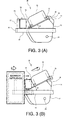
- FIG. 3 is a side view illustrating a deformation of the engine compartment 20 illustrated in FIG. 1 when a barrier intrudes into the engine compartment 20 from the vehicle's front side.
- FIG. 3(A) illustrates the vehicular instrument-mounting structure including the auxiliary battery 14 and the PCU 13 of the engine compartment 20 before collision
- FIG. 3(B) illustrates the vehicular instrument-mounting structure with a displacement of the auxiliary battery 14 caused when the barrier intrudes into the engine compartment 20 and with a displacement of the PCU 13 which is pushed up with the displacement of the auxiliary battery 14.
- FIG. 4 illustrates a PCU disengagement structure 30 in the vehicular instrument-mounting structure
- FIG. 5 illustrates a state in which the PCU 13 is disengaged.
- the PCU disengagement structure 30 illustrated in FIG. 4(A) includes the guide plate 19 attached to the motor case 12 with linkage bolts 32a and 32b, the PCU 13 attached to the guide plate 19 with securing bolts 33, and the male connector 21 and the female connector 31.
- description of the structure which has been already described will be omitted.
- FIG. 4(B) illustrates a top view of the PCU disengagement structure 30, in which the guide plate 19 includes guide holes 35 having a long hole shape and fuse holes 36 having a short hole shape in order to allow disengagement only in the direction of the arrow.
- the linkage bolts (32a and) 32b attached to the fuse holes 36 and the guide holes 35 have two roles.
- the first role is a fuse-like role in which when the impact load applied in the direction of arrow in the figure exceeds the fastening force of the linkage bolts 32a and 32b in the fuse holes 36 and the guide holes 35, the linkage bolt 32a in the fuse hole 36 is released from the fastening of the guide plate 19 to cause the guide plate 19 to start disengaging.
- the second role is a guiding role in which after the linkage bolt 32a of the fuse hole 36 is removed off, the linkage bolt 32b in the guide hole 35 specifies the moving direction of the guide plate 19 and also specifies the frictional resistance.
- FIG. 5(A) illustrates that, after the linkage bolt 32a in the fuse hole 36 is removed, the linkage bolt 32b in the guide hole 35 specifies the moving direction of the guide plate 19, and when the guide plate 19 reaches the end point of the guide hole 35, the linkage bolt 32b in the guide hole 35 restricts further disengagement of the guide plate 19.
- This restriction distance is properly set based on a relationship of the frictional resistance and the impact load between the guide hole 35 and the linkage bolt 32b.
- FIG. 5(B) illustrates a top view of the PCU disengagement structure 30 and illustrates the guide plate 19 and the PCU 13 fixed to the guide plate 19 after disengagement.
- the guide plate is supported at three points by the two linkage bolts 32b in the guide holes 35 and the upper surface of the female connector 31.
- the linkage bolt 32a having a sleeve 34 with a diameter corresponding to the inner diameter of the fuse hole 36 and a thickness h1 corresponding to the thickness h2 of the guide plate 19 inserted therein is illustrated.
- the thickness h1 of the sleeve 34 is set to be thinner than the thickness h2 of the guide plate such that a predetermined frictional force is applied to the guide plate 19 when coupled to the guide plate via the linkage bolts 32a and 32b.
- an appropriate frictional force is applied to the guide plate 19 and also the PCU 13 ascends the slope of an angle of elevation ⁇ , so that impact load absorption in accordance with the weight of the PCU 13 can be applied.
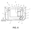
- the auxiliary battery is disposed parallel to the PCU toward the front side of the vehicle with respect to the PCU, an embodiment in which the auxiliary battery is disposed diagonally depending on the restriction of the space in the engine compartment will be described.
- the auxiliary battery By disposing the auxiliary battery at an angle, there is an advantage that the auxiliary battery diagonally pushes the corner portion of the PCU having a relatively high strength, so that the auxiliary battery can turn to make the PCU less deformed and also the distance of squeezing can be reduced.
- FIG. 6 illustrates another embodiment in which the arrangement of the auxiliary battery 14 is modified with respect to the vehicular instrument-mounting structure illustrated in FIG. 1 .
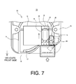
- FIG. 7 is a top view illustrating a deformation of the engine compartment when a barrier intrudes into the engine compartment from the vehicle's front side
- FIG. 8 is a side view illustrating a deformation of the engine compartment when a barrier intrudes into the engine compartment from the vehicle's front side.
- the first stage is a stage of initial collision, in which the barrier comes in contact with the front cross member 18, and the radiator 17 and a corner portion of the auxiliary battery 14 attached to the support platform 23 with the securing piece are pushed into the engine compartment 20 by the barrier.
- the second stage is an impact absorption start stage, in which the front cross member 18 which is squeezed by the barrier transmits the impact load to the side member 15, and the side member 15 and peripheral members of the side member 15 are crushed to thereby absorb the impact load. Further, the auxiliary battery turns its orientation while squeezing the PCU 13 in accordance with the crush of the side member as illustrated in FIG. 7 .
- the third stage is a disengagement stage of the PCU 13 when the barrier further intrudes.
- a portion of the auxiliary battery 14 which is squeezed by the barrier comes into contact with a corner portion on the front surface of the PCU 13, and then, linkage of the linkage means that couples the PCU 13 with the motor case 12 is released.
- the PCU 13 With the squeezing of the auxiliary battery 14, the PCU 13 is allowed to ascend a slope having an elevation angle of ⁇ so that impact load absorption by means of gravity is generated to cause the PCU 13 to disengage and withdraw toward the backward side of the vehicle.
- the PCU 13 discharges the electric charge of the boost converter, the smoothing capacitor and the like by using the internal circuit of the inverter, thereby securing safety.
- the reaction force generated by pushing the motor case with the auxiliary battery can be absorbed by disengaging the power control device at the time of collision. It is therefore possible to discharge the electric charge of high voltage speedily by using a circuit within the power control device.
- the vehicular instrument-mounting structure according to the present embodiment it is possible to eliminate the disadvantages caused by collision even when the auxiliary battery is placed toward the vehicle's front side with respect to the power control device, a high degree of freedom in the layout of the engine compartment can be achieved, so that in vehicles of various sizes and various types, realization of both mounting of the auxiliary battery within the engine compartment and collision safety and also realization of both cost reduction and collision security can be established.
Landscapes
- Engineering & Computer Science (AREA)
- Mechanical Engineering (AREA)
- Chemical & Material Sciences (AREA)
- Combustion & Propulsion (AREA)
- Transportation (AREA)
- Arrangement Or Mounting Of Propulsion Units For Vehicles (AREA)
- Battery Mounting, Suspending (AREA)
- Electric Propulsion And Braking For Vehicles (AREA)
Abstract
Description
- The present invention relates to a vehicular instrument-mounting structure, in which a motor case that stores therein an electric rotating machine for driving a vehicle is disposed in a section formed towards a forward side with respect to a vehicle interior, and a power control device which performs control of the electric rotating machine and an auxiliary battery which supplies electric power to a control section of the power control device are mounted.
- Conventionally, electric vehicles that are driven by a driving force of an electric rotating machine such as a motor generator, hybrid vehicles in which an engine which is an internal combustion engine and an electric rotating machine are used in combination, fuel cell vehicles that driven by electric power generated by a fuel cell, and the like have been known. These vehicles include a power control device having a boost converter, an inverter, and so on, that receives electric power supplied from a main battery or a fuel cell and controls electric power to a motor generator (hereinafter also referred to as a "motor").
- The power control device is also referred to as a PCU (power control unit). As the PCU deals with high voltage and high current, it is necessary to mount the PCU in an engine compartment near the motor generator. Accordingly, in a hybrid vehicle in which an engine is started by a motor generator, because an auxiliary battery for starting the engine does not supply electric power to a cell motor and therefore need not be placed near the engine, and in order to maximize space for disposing the PCU in the engine compartment, the auxiliary battery is disposed in a luggage compartment.
- In recent years, with advancements in downsizing of highvoltage instruments, it has become possible to place the auxiliary battery within the engine compartment and near the power control device. For example,
Patent Document 1 discloses technology of fixing, on a transaxle (also referred to as a motor case) which includes a first motor generator forming a twin-shaft, a second motor generator arranged parallel to an axial line of the first motor generator, and a differential gear arranged on a third axial line parallel to the twin-shaft, a power control device that drives the first motor generator and the second motor generator, which is achieved by downsizing the power control device. With the use of this technology, it is possible to realize downsizing of the power control device and simplification of wiring. - However, in a case in which an auxiliary battery is disposed near a power control device, it is necessary to avoid interference between the auxiliary battery and the power control device in order to perform protection and rapid discharge of the power control device smoothly at the time of vehicle collision in accordance with the regulations for at the time of collision (FMVSS305: Federal Motor Vehicle Safety Standard) of the National Highway Traffic Safety Administration (NHTSA) of the Department of Transportation in the United States. Accordingly, Patent Document 2 discloses a structure having a disengagement mechanism in which, at the time of vehicle collision, due to a load transmitted from an auxiliary battery via a guide surface, which is caused by backward movement of the auxiliary battery with the intrusion of a barrier (obstacle), a relay box moves upward and is separated from a vehicle body. With this mechanism, the battery moves backward smoothly. With such a disengagement structure of the relay box, it is possible to prevent interference between the vehicular instruments and other members that would move as a result of a collision impact and to thereby enhance the impact absorbing effect.
- Further, while the auxiliary battery has a relatively low voltage of 12 volts and therefore damages caused by breakage are not significant, it is desired that damages to the power control device that controls a high voltage such as several hundred volts should be minimized. Accordingly, Patent
Document 3 discloses an instrument-mounting structure in which, in order to protect the power control device itself at the time of vehicle collision, the power control device is mounted such that the front end of the power control device is located further toward the vehicle's rear side with respect to the front end of the transaxle and a motor compressor is placed toward the vehicle's rear side with respect to the power control device, and the auxiliary battery is mounted at the same position of the power control device thereby facilitating protection of the auxiliary battery. - Further, Patent Document 4 discloses an inverter disengagement mechanism which, in order to protect a power control device itself such as an inverter, causes the inverter and an inverter bracket to be disengaged from an inverter tray attached to a front member when an external force is applied to the inverter at the time of collision.
-
- Patent Document 1:
JP 2001-354040 A - Patent Document 2:
JP 2002-362254 A - Patent Document 3:
JP 2010-158991 A - Patent Document 4:
JP 2009-90818 A - While
Patent Document 1 and Patent Document 3 described above disclose technology of fixing the power control device on the transaxle, in a layout in which an auxiliary battery is mounted toward the vehicle's front side with respect to the power control device in relation to other instruments, a corner portion of the auxiliary battery having a relatively high strength partially contacts the power control device to thereby generate a reactive force in a casing of the power control device. When this reactive force exceeds the rigidity of the casing of the power control device, a circuit within the power control device breaks. With such a layout, there are cases in which rapid discharge by using the circuit within the power control device at the time of collision becomes difficult. - Accordingly, in order to protect a circuit within the power control device, it can be considered to increase the rigidity of the casing of the power control device so as to exceed the reactive force generated when the casing is squeezed by the auxiliary battery, or to cause the reactive force to escape by disengaging the power control device from the transaxle at the time of collision, as described in Patent Document 2. However, in the former case, it is necessary to increase the thickness of the plate in order to reinforce the casing rigidity of the power control device, which results in an increase in costs, weight, and physical size, of the power control device. Further, in the latter case, as it is necessary to mount the power control device on the structure member of the vehicle along with the disengagement structure, a limitation in the mounting space arises.
- Accordingly, it is an object of the present invention to provide a vehicular instrument-mounting which is capable of suppressing an impact of an in-vehicle instrument such as a power control device with other members at the time of collision of a vehicle, to thereby suppress damage to the in-vehicle instrument such as the power control device.
- In order to achieve the above object, in accordance with an aspect of the present invention, there is provided a vehicular instrument-mounting structure, in which, in a section formed towards a forward side with respect to a vehicle interior, a motor case that stores therein an electric rotating machine for driving a vehicle is disposed, and a power control device which performs control of the electric rotating machine and an auxiliary battery which supplies electric power to a control section of the power control device are mounted, the vehicular instrument-mounting structure including a guide member for guiding the power control device toward the rear side of the vehicle, and a linkage member for coupling the guide member with an upper surface of the motor case, wherein the linkage member releases linkage between the motor case and the guide member when an impact load is applied to the power control device, with the auxiliary battery being disposed toward the front side of the vehicle with respect to the power control device, and supported such that the auxiliary battery pushes the power control device movably toward the rear side of the vehicle while the auxiliary battery is moved toward the rear side of the vehicle due to the impact load.
- Further, in the vehicular instrument-mounting structure according to the present invention, the auxiliary battery is disposed such that a rear-most end portion of the auxiliary battery is located toward the rear side of the vehicle with respect to a front-most end portion of the power control device.
- Also, in the vehicular instrument-mounting structure according to the present invention, the auxiliary battery is disposed such that a portion of the auxiliary battery is located toward the lateral side with respect to the power control device.
- Furthermore, in the vehicular instrument-mounting structure according to the present invention, a direction of disengagement of the power control device is specified to one direction by the guide member and the linkage member.
- Further, in the vehicular instrument-mounting structure according to the present invention, the auxiliary battery is mounted on a vehicular skeleton member that absorbs the impact load by being crushed in a crush direction.
- Still further, in the vehicular instrument-mounting structure according to the present invention, the motor case is a twin-shaft transaxle having two electrical rotary machines.
- With the application of the vehicular instrument-mounting structure according to the present invention, because, while an auxiliary battery is mounted in a space formed toward the forward direction with respect to a transaxle, which is secured by mounting the power control device on the transaxle, a reactive force generated in the power control device by being pushed by the auxiliary battery at the time of collision can be absorbed due to disengagement of the power control device, it is possible to speedily discharge the electric charge of high voltage by using a circuit within the power control device. As this vehicular instrument-mounting structure can obviate the disadvantages caused by collision even when the auxiliary battery is placed on the forward side with respect to the power control device, there are provided advantages that the degree of freedom is high for the layout of the engine compartment and that, in vehicles of various sizes and types, realization of both mounting of the auxiliary battery within an engine compartment and collision safety can be achieved. There is a further advantage that realization of both cost reduction and collision safety can be achieved.
-
- [
FIG. 1 ]
Schematic view schematically illustrating a vehicular instrument-mounting structure within an engine compartment according to an embodiment of the present invention. - [
FIG. 2 ]
Top view illustrating, from above, a deformation of the engine compartment illustrated inFIG. 1 , when a barrier intrudes from the vehicle's front side. - [
FIG. 3 ]
Side views illustrating, from a lateral side, a deformation of the engine compartment illustrated inFIG. 1 , when a barrier intrudes from the vehicle's front side. - [
FIG. 4 ]
Explanatory views for explaining a disengagement structure of a PCU in the vehicular instrument-mounting structure according to the embodiment of the present invention. - [
FIG. 5 ]
Explanatory views for explaining a state in which the PCU is disengaged in the vehicular instrument-mounting structure illustrated inFIG. 4 . - [
FIG. 6 ]
Explanatory view for explaining another embodiment in which the position of the auxiliary battery is modified with respect to the vehicular instrument-mounting structure illustrated inFIG. 1 . - [
FIG. 7 ]
Top view illustrating, from above, a deformation of the engine compartment illustrated inFIG. 6 , when a barrier intrudes from the vehicle's front side. - [
FIG. 8 ]
Side views illustrating, from a lateral side, a deformation of the engine compartment illustrated inFIG. 6 , when a barrier intrudes from the vehicle's front side. - A best mode for implementing the present invention (which will be referred to as an embodiment) will be described with reference to the drawings.
-
FIG. 1 illustrates an overview of a vehicular instrument-mounting structure within anengine compartment 20 in ahybrid vehicle 10. With reference toFIG. 1 , the vehicular instrument-mounting structure will be generally discussed. Theengine compartment 20 is located toward the front side of thehybrid vehicle 10 with respect to a passenger compartment. Theengine compartment 20 includesside members 15 which are vehicular skeleton members of thehybrid vehicle 10, afront cross member 18 for connecting the twoside members 15, spring supports 16 connected to theside members 15, anauxiliary battery 14 which is disposed further toward the front side of the vehicle with respect to aPCU 13 and is attached to thefront cross member 18 via asupport platform 23 and a securingpiece 22, aradiator 17 which is attached to thefront cross member 18, anengine 11 and amotor case 12 connected to the vehicular skeleton member via an engine mount, anaxle 25 extending from themotor case 12, and thePCU 13 connected to themotor case 12 via aguide plate 19 and a linkage bolt. Further, thePCU 13 includes a boost converter for boosting the voltage of a main battery, an inverter for controlling a boosting coil and a motor generator, and a capacitor for smoothing. Also, amale connector 21 engaging with a female connector of themotor case 12 and a cable connected to the main battery are provided toward the rear side of the vehicle with respect to thePCU 13. - One of the characteristic features of the present embodiment is to disengageably mount the
PCU 13 in a region having a depth formed by a twin-shaft type motor case with theguide plate 19 by using an impact load and to dispose theauxiliary battery 14 toward the front side of the vehicle with respect to thePCU 13. While in the conventional mounting structure a disengagement structure is provided on the vehicular skeleton member such as the front cross member to support the PCU in a disengageable manner, with the disengagement structure being mounted on thePCU 13 as in the present embodiment, it is possible to moderate the restrictions for mounting. With such an arrangement, because, while theauxiliary battery 14 is disposed toward the forward side with respect to thePCU 13, thePCU 13 itself can absorb the impact load by being disengaged at the time of collision, it is possible to speedily discharge the high voltage electric charge in the inverter and the boost converter of thePCU 13 by using an internal circuit of thePCU 13. -
FIG. 2 is a top view illustrating a deformation of theengine compartment 20 when a barrier intrudes into thehybrid vehicle 10 ofFIG. 1 from the vehicle's front side with respect to theengine compartment 20 and right half portion of the vehicle (offset collision). With reference toFIG. 2 , the safety processing for dealing with a collision with a barrier will be described in detail in four separate stages. - The first stage is a stage of initial collision, in which the barrier comes in contact with the
front cross member 18, and theradiator 17 and theauxiliary battery 14 attached to thesupport platform 23 with the securing piece are pushed into theengine compartment 20 by the barrier. - The second stage is an impact absorption start stage, in which the
front cross member 18 which is squeezed by the barrier transmits the impact load to theside member 15, and theside member 15 and peripheral members of theside member 15 are crushed to thereby absorb the impact load. In the case of a relatively small collision, the intrusion of the barrier may be stopped at this stage. - The third stage is a disengagement stage of the
PCU 13 when the barrier further intrudes. Theauxiliary battery 14 which is squeezed by the barrier comes into contact with a front surface of thePCU 13 and squeezes thePCU 13 toward the vehicle's rear side. With the squeezing of thePCU 13, linkage between thePCU 13 and themotor case 12 by a linkage means is released so that thePCU 13 disengages from the motor case and moves toward the backward side of the vehicle. - The fourth stage concerns safety processing of the
PCU 13 after disengagement. When thePCU 13 judges a collision from an air bag or an instruction from a host controller, the host controller or thePCU 13 stops supply of electric power from the main battery to the inverter and the converter, and also thePCU 13 discharges the electric charge of the boost converter, the smoothing capacitor, and the like, by using the internal circuit of the inverter, thereby securing safety. - According to the structure of the present embodiment, the power cable which is connected from the main battery to the
PCU 13 is allowed to have an extra length, corresponding to the disengagement at the time of collision, to maintain connection, and, concerning the connection from thePCU 13 to the motor generator, connection between themale connector 21 and thefemale connector 31 is released with the disengagement of thePCU 13. Here, while the connectors are used in the present embodiment, it is a matter of course that a short generator cable which is broken safely or an isolation terminal block connected with a bus bar whose joint portion is disconnected safely may also be used. -
FIG. 3 is a side view illustrating a deformation of theengine compartment 20 illustrated inFIG. 1 when a barrier intrudes into theengine compartment 20 from the vehicle's front side.FIG. 3(A) illustrates the vehicular instrument-mounting structure including theauxiliary battery 14 and thePCU 13 of theengine compartment 20 before collision, andFIG. 3(B) illustrates the vehicular instrument-mounting structure with a displacement of theauxiliary battery 14 caused when the barrier intrudes into theengine compartment 20 and with a displacement of thePCU 13 which is pushed up with the displacement of theauxiliary battery 14. - In the engine compartment illustrated in
FIG. 3(A) , theside members 15, thefront cross member 18 which is connected to the leading ends of theside members 15, theradiator 17 disposed on thefront cross member 18, theauxiliary battery 14 which is fixed to the radiator attachment portion via thesupport platform 23 and the securingpiece 22, theengine 11 and themotor case 12, theaxle 25 extending from themotor case 12, theguide plate 19 which is disengageably placed on themotor case 12 at an angle of elevation θ, thePCU 13 fixed to theguide plate 19 and thefemale connector 31 attached to themotor case 12, and amale connector 21 which is attached to thePCU 13 and is to be engaged with thefemale connector 31, are arranged. - Now, with reference to
FIG. 3(B) , impact load absorption will be generally discussed. In the engine compartment illustrated inFIG. 3(B) , with the intrusion of the barrier, theauxiliary battery 14 is squeezed in the horizontal direction, and with such squeezing of theauxiliary battery 14, thePCU 13 ascends a slope having an angle of elevation θ so that impact load absorption due to gravity occurs. At this time, the impact load is absorbed by means of a difference between a vertical component and a gravity component of the elevation angle θ, a frictional resistance by the guide plate, and impact load absorption caused by crushing of thefront cross member 18 and theside members 15, and is reduced. Next, the structure of theguide plate 19 will be described in detail. -
FIG. 4 illustrates aPCU disengagement structure 30 in the vehicular instrument-mounting structure, andFIG. 5 illustrates a state in which thePCU 13 is disengaged. ThePCU disengagement structure 30 illustrated inFIG. 4(A) includes theguide plate 19 attached to themotor case 12 withlinkage bolts PCU 13 attached to theguide plate 19 with securingbolts 33, and themale connector 21 and thefemale connector 31. Here, description of the structure which has been already described will be omitted. -
FIG. 4(B) illustrates a top view of thePCU disengagement structure 30, in which theguide plate 19 includes guide holes 35 having a long hole shape and fuseholes 36 having a short hole shape in order to allow disengagement only in the direction of the arrow. The linkage bolts (32a and) 32b attached to the fuse holes 36 and the guide holes 35 have two roles. The first role is a fuse-like role in which when the impact load applied in the direction of arrow in the figure exceeds the fastening force of thelinkage bolts linkage bolt 32a in thefuse hole 36 is released from the fastening of theguide plate 19 to cause theguide plate 19 to start disengaging. The second role is a guiding role in which after thelinkage bolt 32a of thefuse hole 36 is removed off, thelinkage bolt 32b in theguide hole 35 specifies the moving direction of theguide plate 19 and also specifies the frictional resistance. -
FIG. 5(A) illustrates that, after thelinkage bolt 32a in thefuse hole 36 is removed, thelinkage bolt 32b in theguide hole 35 specifies the moving direction of theguide plate 19, and when theguide plate 19 reaches the end point of theguide hole 35, thelinkage bolt 32b in theguide hole 35 restricts further disengagement of theguide plate 19. This restriction distance is properly set based on a relationship of the frictional resistance and the impact load between theguide hole 35 and thelinkage bolt 32b. -
FIG. 5(B) illustrates a top view of thePCU disengagement structure 30 and illustrates theguide plate 19 and thePCU 13 fixed to theguide plate 19 after disengagement. After the disengagement, the guide plate is supported at three points by the twolinkage bolts 32b in the guide holes 35 and the upper surface of thefemale connector 31. Further, in an enlarged view of thelinkage bolt 32a in thefuse hole 36, thelinkage bolt 32a having asleeve 34 with a diameter corresponding to the inner diameter of thefuse hole 36 and a thickness h1 corresponding to the thickness h2 of theguide plate 19 inserted therein is illustrated. Here, the thickness h1 of thesleeve 34 is set to be thinner than the thickness h2 of the guide plate such that a predetermined frictional force is applied to theguide plate 19 when coupled to the guide plate via thelinkage bolts guide plate 19 and also thePCU 13 ascends the slope of an angle of elevation θ, so that impact load absorption in accordance with the weight of thePCU 13 can be applied. - While in the above embodiment, the auxiliary battery is disposed parallel to the PCU toward the front side of the vehicle with respect to the PCU, an embodiment in which the auxiliary battery is disposed diagonally depending on the restriction of the space in the engine compartment will be described. By disposing the auxiliary battery at an angle, there is an advantage that the auxiliary battery diagonally pushes the corner portion of the PCU having a relatively high strength, so that the auxiliary battery can turn to make the PCU less deformed and also the distance of squeezing can be reduced.
-
FIG. 6 illustrates another embodiment in which the arrangement of theauxiliary battery 14 is modified with respect to the vehicular instrument-mounting structure illustrated inFIG. 1 .FIG. 7 is a top view illustrating a deformation of the engine compartment when a barrier intrudes into the engine compartment from the vehicle's front side, andFIG. 8 is a side view illustrating a deformation of the engine compartment when a barrier intrudes into the engine compartment from the vehicle's front side. With reference toFIGs. 6 to 8 , the safety processing against collision with a barrier will be described in detail in four separate stages. Here, description of the structure which has been already described will be omitted. - As illustrated in
FIGs. 7 and8(A) , the first stage is a stage of initial collision, in which the barrier comes in contact with thefront cross member 18, and theradiator 17 and a corner portion of theauxiliary battery 14 attached to thesupport platform 23 with the securing piece are pushed into theengine compartment 20 by the barrier. - The second stage is an impact absorption start stage, in which the
front cross member 18 which is squeezed by the barrier transmits the impact load to theside member 15, and theside member 15 and peripheral members of theside member 15 are crushed to thereby absorb the impact load. Further, the auxiliary battery turns its orientation while squeezing thePCU 13 in accordance with the crush of the side member as illustrated inFIG. 7 . - The third stage is a disengagement stage of the
PCU 13 when the barrier further intrudes. As illustrated inFIG. 8(B) , a portion of theauxiliary battery 14 which is squeezed by the barrier comes into contact with a corner portion on the front surface of thePCU 13, and then, linkage of the linkage means that couples thePCU 13 with themotor case 12 is released. With the squeezing of theauxiliary battery 14, thePCU 13 is allowed to ascend a slope having an elevation angle of θ so that impact load absorption by means of gravity is generated to cause thePCU 13 to disengage and withdraw toward the backward side of the vehicle. - In the fourth stage, for the safety processing of the
PCU 13 after disengagement, thePCU 13 discharges the electric charge of the boost converter, the smoothing capacitor and the like by using the internal circuit of the inverter, thereby securing safety. - As described above, with the application of the vehicular instrument-mounting structure according to the present embodiment, while the auxiliary battery is mounted in a space formed toward the forward side with respect to the transaxle which is secured by mounting the power control device on the transaxle, the reaction force generated by pushing the motor case with the auxiliary battery can be absorbed by disengaging the power control device at the time of collision. It is therefore possible to discharge the electric charge of high voltage speedily by using a circuit within the power control device.
- Further, because with the vehicular instrument-mounting structure according to the present embodiment it is possible to eliminate the disadvantages caused by collision even when the auxiliary battery is placed toward the vehicle's front side with respect to the power control device, a high degree of freedom in the layout of the engine compartment can be achieved, so that in vehicles of various sizes and various types, realization of both mounting of the auxiliary battery within the engine compartment and collision safety and also realization of both cost reduction and collision security can be established.
- 10 hybrid vehicle, 11 engine, 12 motor case, 13 PCU, 14 auxiliary battery, 15 side member, 16 spring support, 17 radiator, 18 front cross member, 19 guide plate, 20 engine compartment, 21 male connector, 22 securing piece, 23 support platform, 25 axle, 30 PCU disengagement structure, 31 female connector, 32a, 32b linkage bolt, 33 securing bolt, 34 sleeve, 35 guide hole, 36 fuse hole
Claims (6)
- A vehicular instrument-mounting structure, in which, in a section formed towards a forward side with respect to a vehicle interior, a motor case that stores therein an electric rotating machine for driving a vehicle is disposed, and a power control device which performs control of the electric rotating machine and an auxiliary battery which supplies electric power to a control section of the power control device are mounted,
the vehicular instrument-mounting structure, comprising:a guide member for guiding the power control device toward the rear side of the vehicle; anda linkage member for coupling the guide member with an upper surface of the motor case,
whereinthe linkage member releases linkage between the motor case and the guide member when an impact load is applied to the power control device, andthe auxiliary battery is disposed toward the front side of the vehicle with respect to the power control device, and is supported such that the auxiliary battery pushes the power control device movably toward the rear side of the vehicle while the auxiliary battery is moved toward the rear side of the vehicle due to the impact load. - The vehicular instrument-mounting structure according to Claim 1, wherein
the auxiliary battery is disposed such that a rear-most end portion of the auxiliary battery is located toward the rear side of the vehicle with respect to a front-most end portion of the power control device. - The vehicular instrument-mounting structure according to Claim 1, wherein
the auxiliary battery is disposed such that a portion of the auxiliary battery is located toward the lateral side with respect to the power control device. - The vehicular instrument-mounting structure according to any one of Claims 1 to 3, wherein
a direction of disengagement of the power control device is specified to one direction by the guide member and the linkage member. - The vehicular instrument-mounting structure according to any one of Claims 1 to 3, wherein
the auxiliary battery is mounted on a vehicular skeleton member that absorbs the impact load by being crushed in a crush direction. - The vehicular instrument-mounting structure according to any one of Claims 1 to 3, wherein
the motor case is a twin-shaft transaxle having two electrical rotary machines.
Applications Claiming Priority (2)
| Application Number | Priority Date | Filing Date | Title |
|---|---|---|---|
| JP2011028363A JP5270702B2 (en) | 2011-02-14 | 2011-02-14 | Vehicle equipment mounting structure |
| PCT/JP2012/053232 WO2012111591A1 (en) | 2011-02-14 | 2012-02-13 | Vehicular instrument-mounting structure |
Publications (3)
| Publication Number | Publication Date |
|---|---|
| EP2636562A1 true EP2636562A1 (en) | 2013-09-11 |
| EP2636562A4 EP2636562A4 (en) | 2014-06-18 |
| EP2636562B1 EP2636562B1 (en) | 2015-05-27 |
Family
ID=46672510
Family Applications (1)
| Application Number | Title | Priority Date | Filing Date |
|---|---|---|---|
| EP12747327.0A Active EP2636562B1 (en) | 2011-02-14 | 2012-02-13 | Vehicular instrument-mounting structure |
Country Status (5)
| Country | Link |
|---|---|
| US (1) | US9254871B2 (en) |
| EP (1) | EP2636562B1 (en) |
| JP (1) | JP5270702B2 (en) |
| CN (1) | CN103370230B (en) |
| WO (1) | WO2012111591A1 (en) |
Cited By (6)
| Publication number | Priority date | Publication date | Assignee | Title |
|---|---|---|---|---|
| WO2015125001A3 (en) * | 2014-02-24 | 2015-11-26 | Toyota Jidosha Kabushiki Kaisha | Mounting structure for vehicle allowing a guided gliding of a electric battery in case of collision |
| FR3023517A1 (en) * | 2014-07-11 | 2016-01-15 | Peugeot Citroen Automobiles Sa | BATTERY SUPPORT WITH PROGRAMMING MOVEMENT |
| WO2016034794A1 (en) * | 2014-09-05 | 2016-03-10 | Renault S.A.S | Vehicle with a non-compressible element attached to a compressible element in case of collision |
| FR3034376A1 (en) * | 2015-04-01 | 2016-10-07 | Peugeot Citroen Automobiles Sa | HOUSING PLACE WITHIN AN ENGINE COMPARTMENT |
| FR3111322A1 (en) * | 2020-06-16 | 2021-12-17 | Psa Automobiles Sa | Vehicle on-board computer support |
| FR3163041A1 (en) * | 2024-06-07 | 2025-12-12 | Stellantis Auto Sas | MOTOR VEHICLE WITH ENHANCED FRONT-END IMPACT SAFETY |
Families Citing this family (54)
| Publication number | Priority date | Publication date | Assignee | Title |
|---|---|---|---|---|
| JP5519559B2 (en) * | 2011-03-10 | 2014-06-11 | トヨタ自動車株式会社 | Protection structure for in-vehicle electrical equipment |
| KR101380476B1 (en) * | 2011-07-26 | 2014-04-01 | 도요타 지도샤(주) | Automobile having vehicle drive motor |
| JP5776622B2 (en) * | 2012-05-08 | 2015-09-09 | トヨタ自動車株式会社 | Electric car |
| CN107804149B (en) * | 2012-10-05 | 2020-08-18 | 日产自动车株式会社 | Mounting structure of equipment for vehicle |
| JP5900320B2 (en) * | 2012-12-27 | 2016-04-06 | トヨタ自動車株式会社 | Vehicle front structure |
| JP5790714B2 (en) * | 2013-06-20 | 2015-10-07 | トヨタ自動車株式会社 | Vehicle lower structure |
| JP5696955B2 (en) | 2013-07-30 | 2015-04-08 | 三菱自動車工業株式会社 | Rotating electric machine for vehicles |
| JP5963117B2 (en) * | 2013-10-04 | 2016-08-03 | トヨタ自動車株式会社 | Power branching device |
| US9321337B2 (en) * | 2013-12-23 | 2016-04-26 | Ford Global Technologies, Llc | Battery array rail assembly with tie bracket |
| US9061714B1 (en) * | 2014-01-24 | 2015-06-23 | Atieva, Inc. | EV battery pack protection system utilizing an undercarriage debris trap |
| JP6063406B2 (en) * | 2014-03-06 | 2017-01-18 | 本田技研工業株式会社 | Fuel cell stack mounting structure |
| JP5979175B2 (en) * | 2014-04-21 | 2016-08-24 | トヨタ自動車株式会社 | Structure for fixing electrical equipment to vehicles |
| JP6098618B2 (en) * | 2014-11-19 | 2017-03-22 | マツダ株式会社 | Automotive front structure |
| DE102015006365B4 (en) | 2015-05-20 | 2021-09-30 | Deutz Aktiengesellschaft | Internal combustion engine with at least one electric motor |
| JP6557531B2 (en) * | 2015-07-21 | 2019-08-07 | 株式会社Subaru | Vehicle structure |
| US9643660B2 (en) | 2015-08-27 | 2017-05-09 | Atieva, Inc. | Bumper assembly for an undercarriage mounted battery pack |
| KR102120664B1 (en) * | 2016-05-25 | 2020-06-09 | 닛산 지도우샤 가부시키가이샤 | Mounting structure of power converter |
| JP6341233B2 (en) * | 2016-06-13 | 2018-06-13 | トヨタ自動車株式会社 | In-vehicle structure of power converter |
| WO2018033880A2 (en) | 2016-08-17 | 2018-02-22 | Shape Corp. | Battery support and protection structure for a vehicle |
| US10062885B2 (en) * | 2016-11-07 | 2018-08-28 | Thomas Gerald Tessier | Battery tray glide system |
| EP3566253B1 (en) | 2017-01-04 | 2022-12-28 | Shape Corp. | Battery support structure for a vehicle |
| JP6536596B2 (en) * | 2017-01-19 | 2019-07-03 | トヨタ自動車株式会社 | On-board structure of power control device |
| US9963028B1 (en) * | 2017-02-21 | 2018-05-08 | Ford Global Technologies, Llc | Battery support structure for electrified vehicle |
| JP6589909B2 (en) * | 2017-03-01 | 2019-10-16 | トヨタ自動車株式会社 | vehicle |
| GB2560519C (en) * | 2017-03-13 | 2021-07-07 | Ford Global Tech Llc | An engine assembly |
| US10886513B2 (en) | 2017-05-16 | 2021-01-05 | Shape Corp. | Vehicle battery tray having tub-based integration |
| US10483510B2 (en) | 2017-05-16 | 2019-11-19 | Shape Corp. | Polarized battery tray for a vehicle |
| WO2018213383A1 (en) | 2017-05-16 | 2018-11-22 | Shape Corp. | Vehicle battery tray with integrated battery retention and support features |
| CN107472006A (en) * | 2017-06-28 | 2017-12-15 | 奇瑞汽车股份有限公司 | A kind of layout pattern of plug-in hybrid-power automobile front deck |
| WO2019055658A2 (en) | 2017-09-13 | 2019-03-21 | Shape Corp. | Vehicle battery tray with tubular peripheral wall |
| US12347879B2 (en) | 2017-09-13 | 2025-07-01 | Shape Corp. | Vehicle battery tray with tubular peripheral wall |
| JP7017047B2 (en) * | 2017-09-14 | 2022-02-08 | トヨタ自動車株式会社 | Vehicle with power control unit |
| DE112018005556T5 (en) | 2017-10-04 | 2020-06-25 | Shape Corp. | BATTERY RACK FLOOR ASSEMBLY FOR ELECTRIC VEHICLES |
| JP6926998B2 (en) * | 2017-12-05 | 2021-08-25 | トヨタ自動車株式会社 | In-vehicle structure of electrical equipment |
| JP7006251B2 (en) * | 2017-12-25 | 2022-01-24 | トヨタ自動車株式会社 | In-vehicle structure of electrical equipment |
| JP7127298B2 (en) * | 2018-02-28 | 2022-08-30 | トヨタ自動車株式会社 | fuel cell vehicle |
| WO2019169080A1 (en) | 2018-03-01 | 2019-09-06 | Shape Corp. | Cooling system integrated with vehicle battery tray |
| US11688910B2 (en) | 2018-03-15 | 2023-06-27 | Shape Corp. | Vehicle battery tray having tub-based component |
| JP7024589B2 (en) * | 2018-05-10 | 2022-02-24 | トヨタ自動車株式会社 | In-vehicle structure of electrical equipment |
| CN112602255B (en) * | 2018-09-03 | 2024-09-17 | 本田技研工业株式会社 | Electric power unit and working machine |
| JP2020078995A (en) * | 2018-11-13 | 2020-05-28 | 本田技研工業株式会社 | Drive unit |
| JP7167720B2 (en) * | 2019-01-10 | 2022-11-09 | トヨタ自動車株式会社 | vehicle |
| JP6871971B2 (en) | 2019-05-28 | 2021-05-19 | 本田技研工業株式会社 | vehicle |
| JP7247815B2 (en) * | 2019-08-23 | 2023-03-29 | マツダ株式会社 | In-vehicle structure of electrical equipment |
| JP7312377B2 (en) * | 2019-09-20 | 2023-07-21 | マツダ株式会社 | engine side structure |
| JP6870786B1 (en) * | 2019-12-25 | 2021-05-12 | 株式会社明電舎 | Mounting structure of motor assembly |
| JP7256146B2 (en) * | 2020-04-28 | 2023-04-11 | トヨタ自動車株式会社 | vehicle rear structure |
| JP7484652B2 (en) * | 2020-10-16 | 2024-05-16 | トヨタ自動車株式会社 | Vehicle compressor mounting structure |
| CN117120288A (en) * | 2021-03-30 | 2023-11-24 | 三菱自动车工业株式会社 | Vehicle inverter mounting structure |
| JP7544087B2 (en) * | 2022-03-02 | 2024-09-03 | トヨタ自動車株式会社 | Support structure for in-vehicle electronic device unit |
| JP2024118327A (en) * | 2023-02-20 | 2024-08-30 | トヨタ自動車株式会社 | Electric vehicles |
| FR3158913B1 (en) * | 2024-02-01 | 2026-01-30 | Ampere Sas | Mounting system for a high-power electronic component of an electric or hybrid vehicle, vehicle chassis including the mounting system and electric or hybrid vehicle including the chassis |
| FR3161165A1 (en) * | 2024-04-11 | 2025-10-17 | Stellantis Auto Sas | MOTOR VEHICLE COMPRISING A PROTECTION DEVICE FOR A MULTI-FUNCTION UNIT |
| CN118288793A (en) * | 2024-05-09 | 2024-07-05 | 浙江极氪智能科技有限公司 | Collision protection component and vehicle |
Family Cites Families (35)
| Publication number | Priority date | Publication date | Assignee | Title |
|---|---|---|---|---|
| US5555950A (en) * | 1992-03-04 | 1996-09-17 | Toyota Jidosha Kabushiki Kaisha | Body structure for electric vehicle |
| JP2932133B2 (en) * | 1993-03-19 | 1999-08-09 | トヨタ自動車株式会社 | Auxiliary parts arrangement structure for electric vehicles |
| JP4081889B2 (en) * | 1998-11-11 | 2008-04-30 | 日産自動車株式会社 | High-voltage harness wiring structure for electric vehicles |
| JP3843702B2 (en) | 2000-06-09 | 2006-11-08 | アイシン・エィ・ダブリュ株式会社 | Driving device for driving electric vehicle |
| JP3923281B2 (en) | 2001-06-13 | 2007-05-30 | 本田技研工業株式会社 | Mounting structure for vehicle equipment |
| JP3867060B2 (en) * | 2003-03-28 | 2007-01-10 | 三菱電機株式会社 | Vehicle power supply system |
| JP2005262894A (en) * | 2004-03-16 | 2005-09-29 | Toyota Motor Corp | Vehicle with high voltage line |
| JP4371036B2 (en) * | 2004-10-20 | 2009-11-25 | 日産自動車株式会社 | Hybrid vehicle inverter buffer structure |
| JP4654691B2 (en) * | 2005-01-18 | 2011-03-23 | 日産自動車株式会社 | Wiring structure of wire harness |
| JP4363391B2 (en) * | 2005-10-13 | 2009-11-11 | トヨタ自動車株式会社 | Electrical component mounting structure |
| JP2007113486A (en) * | 2005-10-20 | 2007-05-10 | Toyota Industries Corp | Vehicular accessary including inverter circuit |
| US7561445B2 (en) * | 2005-11-10 | 2009-07-14 | Nissan Motor Co., Ltd. | Harness routing structure for vehicle |
| JP5141026B2 (en) * | 2006-02-27 | 2013-02-13 | トヨタ自動車株式会社 | In-vehicle structure of power storage pack |
| JP4935112B2 (en) * | 2006-02-28 | 2012-05-23 | トヨタ自動車株式会社 | In-vehicle structure of power storage pack |
| US20100025131A1 (en) * | 2006-04-03 | 2010-02-04 | Bluwav Systems, Llc | Electric propulsion system |
| JP4940749B2 (en) * | 2006-04-28 | 2012-05-30 | トヨタ自動車株式会社 | Power supply device mounting structure |
| US7913786B2 (en) * | 2006-09-29 | 2011-03-29 | Honda Motor Co., Ltd. | Battery mounting system |
| JP2008279955A (en) * | 2007-05-11 | 2008-11-20 | Toyota Motor Corp | Vehicle with fuel cell |
| KR20090006911A (en) * | 2007-07-13 | 2009-01-16 | 현대자동차주식회사 | Arrangement structure of LP cylinder for hybrid vehicle and integrated battery |
| JP2009040263A (en) * | 2007-08-09 | 2009-02-26 | Toyota Motor Corp | Fixed structure for on-vehicle equipment |
| CN101784407B (en) * | 2007-08-24 | 2013-08-14 | 丰田自动车株式会社 | Vehicle |
| JP2009090818A (en) | 2007-10-09 | 2009-04-30 | Toyota Motor Corp | Fixed structure for on-vehicle equipment |
| JP4740982B2 (en) | 2008-06-18 | 2011-08-03 | 東芝テック株式会社 | Programmable logic circuit |
| DE102008058511A1 (en) * | 2008-11-21 | 2010-05-27 | Kostal Industrie Elektrik Gmbh | Frequency converter for controlling an electric motor |
| JP5163486B2 (en) * | 2008-12-25 | 2013-03-13 | トヨタ自動車株式会社 | Power transmission device |
| JP2010158991A (en) | 2009-01-08 | 2010-07-22 | Toyota Industries Corp | Arrangement structure of electric compressor |
| JP5425508B2 (en) * | 2009-03-30 | 2014-02-26 | 矢崎総業株式会社 | Motor cable device and cable body manufacturing method of motor cable device |
| JP2010264793A (en) * | 2009-05-12 | 2010-11-25 | Toyota Motor Corp | Power supply device for vehicle and vehicle |
| US8459399B2 (en) * | 2009-05-28 | 2013-06-11 | Toyota Jidosha Kabushiki Kaisha | Fuel cell system and vehicle |
| JP5252311B2 (en) * | 2009-09-25 | 2013-07-31 | スズキ株式会社 | Hybrid vehicle cooling system |
| JP4826670B2 (en) * | 2009-11-06 | 2011-11-30 | 株式会社豊田自動織機 | Towing tractor |
| US8479858B2 (en) * | 2009-12-03 | 2013-07-09 | Mazda Motor Corporation | Battery arrangement structure of vehicle |
| JP4858607B2 (en) * | 2009-12-14 | 2012-01-18 | トヨタ自動車株式会社 | Power supply |
| US8336657B2 (en) * | 2010-02-12 | 2012-12-25 | Ford Global Technologies, Llc | Support structure for inverter system controller module |
| ITTO20110483A1 (en) * | 2011-06-03 | 2012-12-04 | Oerlikon Graziano Spa | ELECTRIC PROPULSION SYSTEM FOR VEHICLES |
-
2011
- 2011-02-14 JP JP2011028363A patent/JP5270702B2/en not_active Expired - Fee Related
-
2012
- 2012-02-13 US US13/995,387 patent/US9254871B2/en active Active
- 2012-02-13 EP EP12747327.0A patent/EP2636562B1/en active Active
- 2012-02-13 CN CN201280008618.1A patent/CN103370230B/en active Active
- 2012-02-13 WO PCT/JP2012/053232 patent/WO2012111591A1/en not_active Ceased
Cited By (8)
| Publication number | Priority date | Publication date | Assignee | Title |
|---|---|---|---|---|
| WO2015125001A3 (en) * | 2014-02-24 | 2015-11-26 | Toyota Jidosha Kabushiki Kaisha | Mounting structure for vehicle allowing a guided gliding of a electric battery in case of collision |
| FR3023517A1 (en) * | 2014-07-11 | 2016-01-15 | Peugeot Citroen Automobiles Sa | BATTERY SUPPORT WITH PROGRAMMING MOVEMENT |
| WO2016034794A1 (en) * | 2014-09-05 | 2016-03-10 | Renault S.A.S | Vehicle with a non-compressible element attached to a compressible element in case of collision |
| FR3025572A1 (en) * | 2014-09-05 | 2016-03-11 | Renault Sas | VEHICLE WITH AN INCOMPRESSIBLE ELEMENT FIXED ON A COMPRESSIBLE ELEMENT IN CASE OF COLLISION |
| FR3034376A1 (en) * | 2015-04-01 | 2016-10-07 | Peugeot Citroen Automobiles Sa | HOUSING PLACE WITHIN AN ENGINE COMPARTMENT |
| FR3111322A1 (en) * | 2020-06-16 | 2021-12-17 | Psa Automobiles Sa | Vehicle on-board computer support |
| WO2021255359A1 (en) * | 2020-06-16 | 2021-12-23 | Psa Automobiles Sa | Stand for on-board vehicle computer |
| FR3163041A1 (en) * | 2024-06-07 | 2025-12-12 | Stellantis Auto Sas | MOTOR VEHICLE WITH ENHANCED FRONT-END IMPACT SAFETY |
Also Published As
| Publication number | Publication date |
|---|---|
| US20130270862A1 (en) | 2013-10-17 |
| WO2012111591A1 (en) | 2012-08-23 |
| CN103370230B (en) | 2015-11-25 |
| EP2636562A4 (en) | 2014-06-18 |
| JP5270702B2 (en) | 2013-08-21 |
| CN103370230A (en) | 2013-10-23 |
| EP2636562B1 (en) | 2015-05-27 |
| JP2012166653A (en) | 2012-09-06 |
| US9254871B2 (en) | 2016-02-09 |
Similar Documents
| Publication | Publication Date | Title |
|---|---|---|
| EP2636562B1 (en) | Vehicular instrument-mounting structure | |
| EP2711221B1 (en) | Vehicular instrument mounting structure | |
| EP2670613B1 (en) | Vehicle equipment mounting structure | |
| CN107487208B (en) | In-vehicle structure of power converter | |
| EP3228527B1 (en) | Vehicle equipped with traveling motor | |
| JP5712956B2 (en) | Electric vehicle | |
| US8698347B2 (en) | Power unit | |
| JP5602646B2 (en) | Mounting structure of power control device | |
| CN110316110B (en) | Configuration structure of electrical equipment in electric vehicle | |
| JP2019111982A (en) | On-vehicle structure for electric apparatus | |
| EP3287307A1 (en) | Electric device mounting structure | |
| JP6642458B2 (en) | In-vehicle structure of power control unit | |
| JP6597512B2 (en) | In-vehicle structure of power control unit | |
| JP5644661B2 (en) | Vehicle equipment mounting structure | |
| JP6642305B2 (en) | In-vehicle structure of power control unit | |
| JP2018083510A (en) | In-vehicle structure of inverter | |
| JP2013193652A (en) | Electric vehicle | |
| EP4663443A1 (en) | Mechatronic unit and electric vehicle | |
| US20200198704A1 (en) | Protective system for a high voltage module arranged in a crush zone of an electrified vehicle |
Legal Events
| Date | Code | Title | Description |
|---|---|---|---|
| PUAI | Public reference made under article 153(3) epc to a published international application that has entered the european phase |
Free format text: ORIGINAL CODE: 0009012 |
|
| 17P | Request for examination filed |
Effective date: 20130604 |
|
| AK | Designated contracting states |
Kind code of ref document: A1 Designated state(s): AL AT BE BG CH CY CZ DE DK EE ES FI FR GB GR HR HU IE IS IT LI LT LU LV MC MK MT NL NO PL PT RO RS SE SI SK SM TR |
|
| RAP1 | Party data changed (applicant data changed or rights of an application transferred) |
Owner name: TOYOTA JIDOSHA KABUSHIKI KAISHA Owner name: AISIN AW CO., LTD. |
|
| DAX | Request for extension of the european patent (deleted) | ||
| A4 | Supplementary search report drawn up and despatched |
Effective date: 20140516 |
|
| RIC1 | Information provided on ipc code assigned before grant |
Ipc: B60K 1/04 20060101ALI20140512BHEP Ipc: B60R 16/04 20060101AFI20140512BHEP |
|
| RIN1 | Information on inventor provided before grant (corrected) |
Inventor name: HOTTA, YUTAKA Inventor name: YAMANAKA, KENSHI Inventor name: HOTTA, KOJI |
|
| GRAP | Despatch of communication of intention to grant a patent |
Free format text: ORIGINAL CODE: EPIDOSNIGR1 |
|
| INTG | Intention to grant announced |
Effective date: 20141222 |
|
| GRAS | Grant fee paid |
Free format text: ORIGINAL CODE: EPIDOSNIGR3 |
|
| GRAA | (expected) grant |
Free format text: ORIGINAL CODE: 0009210 |
|
| AK | Designated contracting states |
Kind code of ref document: B1 Designated state(s): AL AT BE BG CH CY CZ DE DK EE ES FI FR GB GR HR HU IE IS IT LI LT LU LV MC MK MT NL NO PL PT RO RS SE SI SK SM TR |
|
| REG | Reference to a national code |
Ref country code: GB Ref legal event code: FG4D |
|
| REG | Reference to a national code |
Ref country code: CH Ref legal event code: EP |
|
| REG | Reference to a national code |
Ref country code: AT Ref legal event code: REF Ref document number: 728654 Country of ref document: AT Kind code of ref document: T Effective date: 20150615 |
|
| REG | Reference to a national code |
Ref country code: IE Ref legal event code: FG4D |
|
| REG | Reference to a national code |
Ref country code: DE Ref legal event code: R096 Ref document number: 602012007625 Country of ref document: DE |
|
| REG | Reference to a national code |
Ref country code: AT Ref legal event code: MK05 Ref document number: 728654 Country of ref document: AT Kind code of ref document: T Effective date: 20150527 |
|
| REG | Reference to a national code |
Ref country code: LT Ref legal event code: MG4D |
|
| PG25 | Lapsed in a contracting state [announced via postgrant information from national office to epo] |
Ref country code: HR Free format text: LAPSE BECAUSE OF FAILURE TO SUBMIT A TRANSLATION OF THE DESCRIPTION OR TO PAY THE FEE WITHIN THE PRESCRIBED TIME-LIMIT Effective date: 20150527 Ref country code: PT Free format text: LAPSE BECAUSE OF FAILURE TO SUBMIT A TRANSLATION OF THE DESCRIPTION OR TO PAY THE FEE WITHIN THE PRESCRIBED TIME-LIMIT Effective date: 20150928 Ref country code: NO Free format text: LAPSE BECAUSE OF FAILURE TO SUBMIT A TRANSLATION OF THE DESCRIPTION OR TO PAY THE FEE WITHIN THE PRESCRIBED TIME-LIMIT Effective date: 20150827 Ref country code: ES Free format text: LAPSE BECAUSE OF FAILURE TO SUBMIT A TRANSLATION OF THE DESCRIPTION OR TO PAY THE FEE WITHIN THE PRESCRIBED TIME-LIMIT Effective date: 20150527 Ref country code: LT Free format text: LAPSE BECAUSE OF FAILURE TO SUBMIT A TRANSLATION OF THE DESCRIPTION OR TO PAY THE FEE WITHIN THE PRESCRIBED TIME-LIMIT Effective date: 20150527 Ref country code: FI Free format text: LAPSE BECAUSE OF FAILURE TO SUBMIT A TRANSLATION OF THE DESCRIPTION OR TO PAY THE FEE WITHIN THE PRESCRIBED TIME-LIMIT Effective date: 20150527 |
|
| REG | Reference to a national code |
Ref country code: NL Ref legal event code: MP Effective date: 20150527 |
|
| PG25 | Lapsed in a contracting state [announced via postgrant information from national office to epo] |
Ref country code: BG Free format text: LAPSE BECAUSE OF FAILURE TO SUBMIT A TRANSLATION OF THE DESCRIPTION OR TO PAY THE FEE WITHIN THE PRESCRIBED TIME-LIMIT Effective date: 20150827 Ref country code: RS Free format text: LAPSE BECAUSE OF FAILURE TO SUBMIT A TRANSLATION OF THE DESCRIPTION OR TO PAY THE FEE WITHIN THE PRESCRIBED TIME-LIMIT Effective date: 20150527 Ref country code: IS Free format text: LAPSE BECAUSE OF FAILURE TO SUBMIT A TRANSLATION OF THE DESCRIPTION OR TO PAY THE FEE WITHIN THE PRESCRIBED TIME-LIMIT Effective date: 20150927 Ref country code: AT Free format text: LAPSE BECAUSE OF FAILURE TO SUBMIT A TRANSLATION OF THE DESCRIPTION OR TO PAY THE FEE WITHIN THE PRESCRIBED TIME-LIMIT Effective date: 20150527 Ref country code: LV Free format text: LAPSE BECAUSE OF FAILURE TO SUBMIT A TRANSLATION OF THE DESCRIPTION OR TO PAY THE FEE WITHIN THE PRESCRIBED TIME-LIMIT Effective date: 20150527 Ref country code: GR Free format text: LAPSE BECAUSE OF FAILURE TO SUBMIT A TRANSLATION OF THE DESCRIPTION OR TO PAY THE FEE WITHIN THE PRESCRIBED TIME-LIMIT Effective date: 20150828 |
|
| PG25 | Lapsed in a contracting state [announced via postgrant information from national office to epo] |
Ref country code: DK Free format text: LAPSE BECAUSE OF FAILURE TO SUBMIT A TRANSLATION OF THE DESCRIPTION OR TO PAY THE FEE WITHIN THE PRESCRIBED TIME-LIMIT Effective date: 20150527 Ref country code: EE Free format text: LAPSE BECAUSE OF FAILURE TO SUBMIT A TRANSLATION OF THE DESCRIPTION OR TO PAY THE FEE WITHIN THE PRESCRIBED TIME-LIMIT Effective date: 20150527 |
|
| PG25 | Lapsed in a contracting state [announced via postgrant information from national office to epo] |
Ref country code: PL Free format text: LAPSE BECAUSE OF FAILURE TO SUBMIT A TRANSLATION OF THE DESCRIPTION OR TO PAY THE FEE WITHIN THE PRESCRIBED TIME-LIMIT Effective date: 20150527 Ref country code: SK Free format text: LAPSE BECAUSE OF FAILURE TO SUBMIT A TRANSLATION OF THE DESCRIPTION OR TO PAY THE FEE WITHIN THE PRESCRIBED TIME-LIMIT Effective date: 20150527 Ref country code: CZ Free format text: LAPSE BECAUSE OF FAILURE TO SUBMIT A TRANSLATION OF THE DESCRIPTION OR TO PAY THE FEE WITHIN THE PRESCRIBED TIME-LIMIT Effective date: 20150527 Ref country code: RO Free format text: LAPSE BECAUSE OF NON-PAYMENT OF DUE FEES Effective date: 20150527 |
|
| REG | Reference to a national code |
Ref country code: DE Ref legal event code: R097 Ref document number: 602012007625 Country of ref document: DE |
|
| PLBE | No opposition filed within time limit |
Free format text: ORIGINAL CODE: 0009261 |
|
| STAA | Information on the status of an ep patent application or granted ep patent |
Free format text: STATUS: NO OPPOSITION FILED WITHIN TIME LIMIT |
|
| PG25 | Lapsed in a contracting state [announced via postgrant information from national office to epo] |
Ref country code: IT Free format text: LAPSE BECAUSE OF FAILURE TO SUBMIT A TRANSLATION OF THE DESCRIPTION OR TO PAY THE FEE WITHIN THE PRESCRIBED TIME-LIMIT Effective date: 20150527 |
|
| 26N | No opposition filed |
Effective date: 20160301 |
|
| PG25 | Lapsed in a contracting state [announced via postgrant information from national office to epo] |
Ref country code: BE Free format text: LAPSE BECAUSE OF NON-PAYMENT OF DUE FEES Effective date: 20160229 Ref country code: SI Free format text: LAPSE BECAUSE OF FAILURE TO SUBMIT A TRANSLATION OF THE DESCRIPTION OR TO PAY THE FEE WITHIN THE PRESCRIBED TIME-LIMIT Effective date: 20150527 |
|
| PG25 | Lapsed in a contracting state [announced via postgrant information from national office to epo] |
Ref country code: BE Free format text: LAPSE BECAUSE OF FAILURE TO SUBMIT A TRANSLATION OF THE DESCRIPTION OR TO PAY THE FEE WITHIN THE PRESCRIBED TIME-LIMIT Effective date: 20150527 |
|
| PG25 | Lapsed in a contracting state [announced via postgrant information from national office to epo] |
Ref country code: MC Free format text: LAPSE BECAUSE OF FAILURE TO SUBMIT A TRANSLATION OF THE DESCRIPTION OR TO PAY THE FEE WITHIN THE PRESCRIBED TIME-LIMIT Effective date: 20150527 Ref country code: LU Free format text: LAPSE BECAUSE OF FAILURE TO SUBMIT A TRANSLATION OF THE DESCRIPTION OR TO PAY THE FEE WITHIN THE PRESCRIBED TIME-LIMIT Effective date: 20160213 |
|
| REG | Reference to a national code |
Ref country code: CH Ref legal event code: PL |
|
| GBPC | Gb: european patent ceased through non-payment of renewal fee |
Effective date: 20160213 |
|
| PG25 | Lapsed in a contracting state [announced via postgrant information from national office to epo] |
Ref country code: LI Free format text: LAPSE BECAUSE OF NON-PAYMENT OF DUE FEES Effective date: 20160229 Ref country code: CH Free format text: LAPSE BECAUSE OF NON-PAYMENT OF DUE FEES Effective date: 20160229 |
|
| REG | Reference to a national code |
Ref country code: FR Ref legal event code: ST Effective date: 20161028 |
|
| REG | Reference to a national code |
Ref country code: IE Ref legal event code: MM4A |
|
| PG25 | Lapsed in a contracting state [announced via postgrant information from national office to epo] |
Ref country code: IE Free format text: LAPSE BECAUSE OF NON-PAYMENT OF DUE FEES Effective date: 20160213 Ref country code: GB Free format text: LAPSE BECAUSE OF NON-PAYMENT OF DUE FEES Effective date: 20160213 Ref country code: FR Free format text: LAPSE BECAUSE OF NON-PAYMENT OF DUE FEES Effective date: 20160229 |
|
| PG25 | Lapsed in a contracting state [announced via postgrant information from national office to epo] |
Ref country code: SE Free format text: LAPSE BECAUSE OF FAILURE TO SUBMIT A TRANSLATION OF THE DESCRIPTION OR TO PAY THE FEE WITHIN THE PRESCRIBED TIME-LIMIT Effective date: 20150527 Ref country code: NL Free format text: LAPSE BECAUSE OF FAILURE TO SUBMIT A TRANSLATION OF THE DESCRIPTION OR TO PAY THE FEE WITHIN THE PRESCRIBED TIME-LIMIT Effective date: 20150527 |
|
| PG25 | Lapsed in a contracting state [announced via postgrant information from national office to epo] |
Ref country code: MT Free format text: LAPSE BECAUSE OF FAILURE TO SUBMIT A TRANSLATION OF THE DESCRIPTION OR TO PAY THE FEE WITHIN THE PRESCRIBED TIME-LIMIT Effective date: 20150527 |
|
| PG25 | Lapsed in a contracting state [announced via postgrant information from national office to epo] |
Ref country code: CY Free format text: LAPSE BECAUSE OF FAILURE TO SUBMIT A TRANSLATION OF THE DESCRIPTION OR TO PAY THE FEE WITHIN THE PRESCRIBED TIME-LIMIT Effective date: 20150527 Ref country code: HU Free format text: LAPSE BECAUSE OF FAILURE TO SUBMIT A TRANSLATION OF THE DESCRIPTION OR TO PAY THE FEE WITHIN THE PRESCRIBED TIME-LIMIT; INVALID AB INITIO Effective date: 20120213 Ref country code: SM Free format text: LAPSE BECAUSE OF FAILURE TO SUBMIT A TRANSLATION OF THE DESCRIPTION OR TO PAY THE FEE WITHIN THE PRESCRIBED TIME-LIMIT Effective date: 20150527 |
|
| PG25 | Lapsed in a contracting state [announced via postgrant information from national office to epo] |
Ref country code: TR Free format text: LAPSE BECAUSE OF FAILURE TO SUBMIT A TRANSLATION OF THE DESCRIPTION OR TO PAY THE FEE WITHIN THE PRESCRIBED TIME-LIMIT Effective date: 20150527 Ref country code: MT Free format text: LAPSE BECAUSE OF FAILURE TO SUBMIT A TRANSLATION OF THE DESCRIPTION OR TO PAY THE FEE WITHIN THE PRESCRIBED TIME-LIMIT Effective date: 20160229 Ref country code: MK Free format text: LAPSE BECAUSE OF FAILURE TO SUBMIT A TRANSLATION OF THE DESCRIPTION OR TO PAY THE FEE WITHIN THE PRESCRIBED TIME-LIMIT Effective date: 20150527 |
|
| PG25 | Lapsed in a contracting state [announced via postgrant information from national office to epo] |
Ref country code: AL Free format text: LAPSE BECAUSE OF FAILURE TO SUBMIT A TRANSLATION OF THE DESCRIPTION OR TO PAY THE FEE WITHIN THE PRESCRIBED TIME-LIMIT Effective date: 20150527 |
|
| P01 | Opt-out of the competence of the unified patent court (upc) registered |
Effective date: 20231024 |
|
| PGFP | Annual fee paid to national office [announced via postgrant information from national office to epo] |
Ref country code: DE Payment date: 20251230 Year of fee payment: 15 |