EP2636558A1 - Seat frame for vehicle - Google Patents
Seat frame for vehicle Download PDFInfo
- Publication number
- EP2636558A1 EP2636558A1 EP11838090.6A EP11838090A EP2636558A1 EP 2636558 A1 EP2636558 A1 EP 2636558A1 EP 11838090 A EP11838090 A EP 11838090A EP 2636558 A1 EP2636558 A1 EP 2636558A1
- Authority
- EP
- European Patent Office
- Prior art keywords
- seat
- side member
- wall portion
- belt
- seat back
- Prior art date
- Legal status (The legal status is an assumption and is not a legal conclusion. Google has not performed a legal analysis and makes no representation as to the accuracy of the status listed.)
- Granted
Links
Images




Classifications
-
- B—PERFORMING OPERATIONS; TRANSPORTING
- B60—VEHICLES IN GENERAL
- B60N—SEATS SPECIALLY ADAPTED FOR VEHICLES; VEHICLE PASSENGER ACCOMMODATION NOT OTHERWISE PROVIDED FOR
- B60N2/00—Seats specially adapted for vehicles; Arrangement or mounting of seats in vehicles
- B60N2/68—Seat frames
- B60N2/688—Particular seat belt attachment and guiding
-
- B—PERFORMING OPERATIONS; TRANSPORTING
- B60—VEHICLES IN GENERAL
- B60N—SEATS SPECIALLY ADAPTED FOR VEHICLES; VEHICLE PASSENGER ACCOMMODATION NOT OTHERWISE PROVIDED FOR
- B60N2/00—Seats specially adapted for vehicles; Arrangement or mounting of seats in vehicles
- B60N2/68—Seat frames
- B60N2/682—Joining means
-
- B—PERFORMING OPERATIONS; TRANSPORTING
- B60—VEHICLES IN GENERAL
- B60N—SEATS SPECIALLY ADAPTED FOR VEHICLES; VEHICLE PASSENGER ACCOMMODATION NOT OTHERWISE PROVIDED FOR
- B60N2/00—Seats specially adapted for vehicles; Arrangement or mounting of seats in vehicles
- B60N2/64—Back-rests or cushions
- B60N2/643—Back-rests or cushions shape of the back-rests
Definitions
- the present invention relates to a seat frame for a vehicle.
- a seat frame including: a seat cushion frame for supporting a seat cushion of a seat of a vehicle; and a seat back frame to which a retractor (seat belt retaining member) is coupled, the seat back frame being coupled to the seat cushion frame, and supporting a seat back of the seat.
- Patent Literature 1 discloses a seat back frame including: a pipe frame extending along a contour of a seat back; and a tower frame provided so as to extend in an up-and-down direction of a vehicle. To an upper portion of the tower frame of the seat back frame, a belt guide portion is mounted. The belt guide portion guides a shoulder belt for holding a shoulder portion of an occupant. Further, a bracket is fixed to a lower pipe (lower cross member) formed on an inner side of a lower portion of the tower frame, and a retractor (seat belt retaining member) for winding a seat belt is fixed to the bracket.
- the tower frame of the seat frame described in Patent Literature 1 includes: an outer wall member shaped into a rectangular column and including an outer side bracket and an inner side bracket; and an insert brace provided inside the outer wall member. Both the brackets and the insert brace are partially connected together by welding. The insert brace reinforces the tower frame.
- the tower frame forming the seat back frame is reinforced by the insert brace.
- the insert brace is not designed in consideration of a direction of tension that the seat back frame receives from the seat belt. Therefore, rigidity of the seat back frame with respect to the tension of the seat belt is not greatly increased.
- the tower frame is formed of three sheets of steel plates (outer side bracket, inner side bracket, and insert brace), and the three sheets of steel plates are partially joined together at certain intervals by spot welding. Accordingly, the tower frame is more likely to buckle and deform in a portion between joining points.
- the number of components is increased and man-hours for welding are increased, which leads to increase in cost.
- the present invention has been made in order to solve the above-mentioned problems, and has an object to provide a seat frame including a seat back frame having a relatively simple configuration and having increased rigidity with respect to the tension of the seat belt.
- a seat frame including: a seat cushion frame for supporting a seat cushion of a seat of a vehicle; and a seat back frame to which a seat belt retaining member is coupled, the seat back frame being coupled to the seat cushion frame and supporting a seat back of the seat, the seat belt retaining member retaining one end of a seat belt for holding an occupant seated on the seat.
- the seat back frame includes: a first side member and a second side member each formed into an elongated shape along an up-and-down direction of the seat back so as to support each side portion of the seat back; and a belt guide portion on which tension of the seat belt is applied when the seat belt is pulled, the belt guide portion being formed in an upper portion of the first side member and guiding the seat belt having the one end retained by the seat belt retaining member.
- the first side member is formed of one sheet of steel plate, and includes: a side member side wall portion formed in parallel to a direction of application of the tension of the seat belt on the belt guide portion and formed continuously along a longitudinal direction of the first side member; a side member front wall portion formed on a front side of the vehicle with respect to the side member side wall portion; and a side member rear wall portion formed on a rear side of the vehicle with respect to the side member side wall portion, the first side member having an open cross-sectional shape.
- the belt guide portion is formed in the upper portion of the first side member.
- the belt guide portion guides the seat belt, and receives the tension of the seat belt when the seat belt is pulled.
- the first side member includes the side member side wall portion, the side member front wall portion, and the side member rear wall portion.
- the side member side wall portion is formed along the longitudinal direction of the first side member.
- the side member side wall portion is formed in parallel to the direction of application of the tension of the seat belt on the belt guide portion. Therefore, when the tension of the seat belt is applied onto the belt guide portion, the side member side wall portion effectively functions as a reinforcing portion against the tension. Accordingly, it is possible to provide the seat frame including the seat back frame having increased rigidity with respect to the tension of the seat belt.
- the first side member is formed of one sheet of steel plate. Accordingly, the number of components is reduced, and thus it is possible to reduce a manufacturing cost of the seat frame.
- the first side member has the open cross-sectional shape, and it is unnecessary to weld a plurality of sheets of steel plate together so as to form a closed cross-section. As a result, man-hours for working such as welding are reduced. Accordingly, it is possible to further reduce the manufacturing cost of the seat frame.
- the open cross-sectional shape means an unclosed cross-sectional shape.
- the first side member and the belt guide portion be integrally molded from one sheet of steel plate. In this way, it is possible to further reduce the manufacturing cost of the seat frame.
- the side member front wall portion include a front projecting portion projecting to an outer side of the seat back with respect to the side member side wall portion
- the side member rear wall portion include a rear projecting portion projecting to the outer side of the seat back with respect to the side member side wall portion.
- the front projecting portion and the rear projecting portion be formed continuously along the longitudinal direction of the first side member, and the front projecting portion have a projecting amount larger than a projecting amount of the rear projecting portion.
- the front projecting portion forms a ridge formed on the front side of the vehicle with respect to the side member side wall portion along the longitudinal direction of the first side member
- the rear projecting portion forms a ridge formed on the rear side of the vehicle with respect to the side member side wall portion along the longitudinal direction of the first side member.
- the ridge (front projecting portion) which is formed on the front side of the vehicle with respect to the side member side wall portion, prevents the first side member from buckling and deforming when the first side member is pulled to the front side of the vehicle.
- the ridge which is formed on the rear side of the vehicle with respect to the side member side wall portion, prevents the first side member from buckling and deforming when the first side member is pulled to the rear side of the vehicle.
- the front projecting portion has the projecting amount larger than the projecting amount of the rear projecting portion. Therefore, when the first side member is pulled to the front side of the vehicle by a large force, for example, at the time of sudden braking of the vehicle, the first side member is more effectively prevented from buckling and deforming.
- the belt guide portion include: a belt guide side wall portion formed in parallel to the direction of application of the tension of the seat belt on the belt guide portion; a belt guide front wall portion formed on the front side of the vehicle with respect to the belt guide side wall portion so as to extend to an inner side of the seat back; and a belt guide rear wall portion formed on the rear side of the vehicle with respect to the belt guide side wall portion so as to extend to the inner side of the seat back.
- the belt guide portion which is formed in the upper portion of the first side member, includes the belt guide side wall portion formed in parallel to the direction of application of the tension of the seat belt. Accordingly, rigidity with respect to the tension of the seat belt is further increased.
- the belt guide front wall portion and the belt guide rear wall portion each include a portion orthogonal to the direction of application of the tension of the seat belt on the belt guide portion.
- the belt guide front wall portion and the belt guide rear wall portion are formed in a direction orthogonal to the direction of application of the tension of the seat belt on the belt guide portion, and hence the seat belt is prevented from slipping off when the seat belt is hung over the belt guide portion. Accordingly, the tension of the seat belt is correctly applied in a direction of formation of the belt guide side wall portion.
- the first side member be produced by die quenching. That is, it is preferred that the first side member be molded in a die assembly and quenched in the die assembly through contact with dies. In this way, the first side member including the side member side wall portion, the side member front wall portion, and the side member rear wall portion can be molded from one sheet of steel plate by, for example, pressing. Further, the first side member molded in the die assembly is quenched and hardened through contact with the dies, and thus it is possible to increase strength of the first side member. Note that, in this case, the first side member and the belt guide portion are integrally molded by die quenching, and thus it is possible to further reduce the manufacturing cost.
- the seat back frame include a cross member for coupling the first side member and the second side member together.
- the cross member be set to have a vertical length larger than a widthwise length thereof in cross-section.
- the cross member has a vertically elongated shape in cross-section, and hence also a recess, which is formed in the first side member in order to fix the cross member, is formed into a vertically elongated shape.
- the recess formed in the first side member can be formed into a vertically elongated shape, and thus an area of the recess formed in the first side member is correspondingly reduced. Consequently, the cross member can be supported by the first side member while preventing reduction in strength of the first side member that is accompanied with formation of the recess.
- the seat belt retaining member be mounted to the cross member.
- FIG. 1 is a perspective view of a seat frame according to this embodiment
- FIG. 2 is a front view of the seat frame.
- a seat frame 1 according to this embodiment includes a seat cushion frame 10 and a seat back frame 20.
- the seat cushion frame 10 supports a seat cushion 30 serving as a portion to be seated of a seat of a vehicle.
- the seat back frame 20 supports a seat back 40 serving as a backrest portion of the seat of the vehicle.
- the seat back frame 20 is swingably coupled to the seat cushion frame 10 through the intermediation of a recliner 50.
- the seat cushion frame 10 includes a seat cushion right-hand side member 11, a seat cushion left-hand side member 12, and a coupling member 13.
- the seat cushion right-hand side member 11 is arranged under a right-hand side portion of the seat cushion 30, and the seat cushion left-hand side member 12 is arranged under a left-hand side portion of the seat cushion 30.
- a right-and-left direction corresponds to a direction viewed from an occupant who is seated on the seat of the vehicle.
- the seat cushion right-hand side member 11 is formed into an elongated shape along a fore-and-aft direction of the vehicle.
- the seat cushion right-hand side member 11 is coupled at its proximal end portion 11 a to a seat back right-hand side member 21 described later through the intermediation of the recliner 50.
- the seat cushion left-hand side member 12 is formed into an elongated shape along the fore-and-aft direction of the vehicle.
- the seat cushion left-hand side member 12 is coupled at its proximal end portion 12a to a seat back left-hand side member 22 described later.
- the coupling member 13 couples a distal end portion 11 b of the seat cushion right-hand side member 11 and a distal end portion 12b of the seat cushion left-hand side member 12 together.
- rail guide members 62, 62 which are fitted respectively onto seat rails 61, 61 formed along the fore-and-aft direction of the vehicle, are connected to a lower surface of the seat cushion right-hand side member 11 and a lower surface of the seat cushion left-hand side member 12, respectively. Therefore, the rail guide members 62, 62 move along the seat rails 61, 61, and thus a position of the seat frame 1 is adjusted in its fore-and-aft direction.
- the seat back frame 20 includes the seat back right-hand side member 21, the seat back left-hand side member 22, an upper cross member 23, and a lower cross member 24.
- the seat back right-hand side member 21 supports the right-hand side portion of the seat back 40
- the seat back left-hand side member 22 supports the left-hand side portion of the seat back 40.
- the side members 21, 22 are each formed into an elongated shape along an up-and-down direction of the seat back 40.
- the seat back right-hand side member 21 is coupled to the proximal end portion 11 a of the seat cushion right-hand side member 11 through the intermediation of the recliner 50 at a recliner fixing portion 21 a formed at a lower end portion of the seat back right-hand side member 21.
- the seat back left-hand side member 22 is coupled at its lower end portion 22a to the proximal end portion 12a of the seat cushion left-hand side member 12.
- the upper cross member 23 extends in a vehicle width direction, and couples an upper end portion 21 b of the seat back right-hand side member 21 and an upper end portion 22b of the seat back left-hand side member 22 together.
- the lower cross member 24 extends in the vehicle width direction, and couples a slightly lower portion of the seat back right-hand side member 21 and a slightly lower portion of the seat back left-hand side member 22 together.
- FIG. 3 is a cross-sectional view taken along the line III-III of FIG. 2 , that is, a cross-sectional view of the lower cross member 24.
- the lower cross member 24 is a hollow member.
- the lower cross member 24 can be processed, for example, by squeezing a pipe having a circular cross-section.
- the lower cross member 24 has a cross-section elongated in the up-and-down direction, and has such a shape that circular portions are formed respectively at both end portions in the up-and-down direction of the lower cross member 24 so as to be connected to each other by parallel straight portions.
- the lower cross member 24 has a vertical length H larger than a widthwise length W thereof.
- FIG. 4 is a cross-sectional view taken along the line IV-IV of FIG. 2 .
- a bolt insertion hole 241 passing through the lower cross member 24 in its width direction is formed in the lower cross member 24 in its width direction.
- a bolt BT is inserted through the bolt insertion hole 241.
- the bolt BT and a nut NT threadingly engaged with the bolt BT fix a bracket 25 to the lower cross member 24.
- a retractor (seat belt retaining member) 26 is fixed to a distal end of the bracket 25. That is, the retractor 26 is fixed to the lower cross member 24 through the intermediation of the bracket 25.
- the retractor 26 retains one end of a seat belt. Further, the retractor 26 may wind the seat belt in a case where predetermined tension is applied from the seat belt.
- FIG. 5 is a left-hand side view of the seat back frame 20.
- the seat back left-hand side member 22 becomes narrower as extending upward and is warped rearward in side view.
- a first recess 22c and a second recess 22d are formed in the seat back left-hand side member 22.
- the first recess 22c has the same shape as a cross-section of a contour of the lower cross member 24, and the second recess 22d has the same shape as a cross-section of a contour of the upper cross member 23.
- the upper cross member 23 has substantially a rectangular cross-sectional shape.
- a belt guide portion 27 is formed in an upper portion of the seat back right-hand side member 21.
- the belt guide portion 27 guides a seat belt 29 retained by the retractor 26 at one end.
- the seat belt 29 is hung over the belt guide portion 27.
- a tongue plate (not shown) is provided at an intermediate portion of the seat belt 29 which is hung over the belt guide portion 27, and the tongue plate is fixed to a buckle 70 provided below the seat back left-hand side member 22 (see FIG. 2 ).
- another end of the seat belt 29 is fixed to an anchor plate (not shown) provided below the seat back right-hand side member 21. Therefore, the occupant is held from a right shoulder side to a left lower back side by a part of the seat belt stretching between the belt guide portion 27 and the buckle 70 (tongue plate).
- FIGS. 6 are views illustrating the seat back right-hand side member 21 and the belt guide portion 27.
- FIG. 6(a) is a top view of the seat back right-hand side member 21 and the belt guide portion 27,
- FIG. 6(b) is a front view thereof
- FIG. 6(c) is a right-hand side view thereof.
- the seat back right-hand side member 21 becomes narrower as extending upward and is warped rearward in side view.
- a first recess 21 c and a second recess 21 d are formed in the seat back right-hand side member 21.
- first recess 21 c another end of the lower cross member 24 is inserted, and in the second recess 21 d, another end of the upper cross member 23 is inserted.
- the first recess 21 c formed in the seat back right-hand side member 21 and the first recess 22c formed in the seat back left-hand side member 22 have the same shape.
- the first recesses 21 c, 22c support the lower cross member 24.
- the second recess 21 d formed in the seat back right-hand side member 21 and the second recess 22d formed in the seat back left-hand side member 22 have the same shape.
- the second recesses 21 d, 22d support the upper cross member 23.
- the recliner fixing portion 21a is formed at a lowermost portion of the seat back right-hand side member 21.
- the recliner 50 is fixed to the recliner fixing portion 21 a.
- the recliner 50 adjusts an angle of the seat back frame 20 with respect to the seat cushion frame 10.
- a configuration of the recliner 50 is well-known, and hence description thereof is omitted.
- FIG. 7 is a cross-sectional view taken along the line VII-VII of FIG. 2 .
- FIG. 7 illustrates a cross-sectional shape of the seat back right-hand side member 21 in a vicinity of a center in a longitudinal direction thereof.
- the seat back right-hand side member 21 includes: a side member side wall portion 211 formed into a straight portion at substantially a center portion thereof in the fore-and-aft direction of the vehicle; a side member front wall portion 212 formed on a front side of the vehicle (lower side of FIG. 7 ) with respect to the straight portion; and a side member rear wall portion 213 formed on a rear side of the vehicle (upper side of FIG. 7 ) with respect to the straight portion.
- the side member side wall portion 211 is inclined at an angle ⁇ with respect to the fore-and-aft direction of the vehicle. Specifically, the side member side wall portion 211 is inclined at the angle ⁇ with respect to the fore-and-aft direction of the vehicle so as to be inclined inward from an outer side of the vehicle as extending from the rear side of the vehicle to the front side of the vehicle.
- the side member front wall portion 212 includes a front projecting portion 212a projecting outward (to the outer side of the seat back 40: left side of FIG. 7 ) with respect to the side member side wall portion 211.
- the side member rear wall portion 213 includes a rear projecting portion 213a projecting outward with respect to the side member side wall portion 211.
- the front projecting portion 212a has a projecting amount larger than a projecting amount of the rear projecting portion 213a.
- FIGS. 8 to 16 are respectively a cross-sectional view ( FIG. 8 ) taken along the line VIII-VIII of FIG. 6(b) , a cross-sectional view ( FIG. 9 ) taken along the line IX-IX of FIG. 6(b) , a cross-sectional view ( FIG. 10 ) taken along the line X-X of FIG. 6(b) , a cross-sectional view ( FIG. 11 ) taken along the line XI-XI of FIG. 6(b) , a cross-sectional view ( FIG. 12 ) taken along the line XII-XII of FIG. 6(b) , a cross-sectional view ( FIG. 13 ) taken along the line XIII-XIII of FIG.
- FIGS. 8 to 13 are cross-sectional views illustrating the upper portion of the seat back right-hand side member 21 in the longitudinal direction thereof.
- FIGS. 14 to 16 are cross-sectional views of the belt guide portion 27.
- the upper portion of the seat back right-hand side member 21 includes: the side member side wall portion 211 formed into a straight portion at substantially the center portion thereof in the fore-and-aft direction of the vehicle; the side member front wall portion 212 formed on the front side of the vehicle (lower side of FIG. 8, 9 , 10, or 11 ) with respect to the side member side wall portion 211; and the side member rear wall portion 213 formed on the rear side of the vehicle (upper side of FIG. 8, 9 , 10, or 11 ) with respect to the side member side wall portion 211.
- the front projecting portion 212a is formed in the side member front wall portion 212
- the rear projecting portion 213a is formed in the side member rear wall portion 213.
- the front projecting portion 212a has the projecting amount larger than the projecting amount of the rear projecting portion 213a.
- the second recess 21 d is formed in the seat back right-hand side member 21 at a position in cross-section illustrated in FIGS. 12 and 13 , and hence the side member side wall portion 211, the front projecting portion 212a, and the rear projecting portion 213a are not shown in FIGS. 12 and 13 .
- the side member side wall portion 211 illustrated in FIGS. 8 to 11 is inclined at the angle ⁇ with respect to the fore-and-aft direction of the vehicle.
- the side member side wall portion 211 is formed continuously as illustrated in FIGS. 7 to 11 . That is, a side wall, which is inclined at the angle ⁇ with respect to the fore-and-aft direction of the vehicle so as to be inclined inward from the outer side of the vehicle as extending from the rear side of the vehicle to the front side of the vehicle, is formed continuously in the seat back right-hand side member 21 along the longitudinal direction of the seat back right-hand side member 21.
- the front projecting portion 212a and the rear projecting portion 213a illustrated FIGS. 7 to 11 are formed continuously. That is, a ridge formed by the front projecting portion 212a is formed continuously on the front side of the vehicle with respect to the side member side wall portion 211 along the longitudinal direction of the seat back right-hand side member 21, and a ridge formed by the rear projecting portion 213a is formed continuously on the rear side of the vehicle with respect to the side member side wall portion 211 along the longitudinal direction of the seat back right-hand side member 21.
- the ridge formed on the front side of the vehicle with respect to the side member side wall portion 211 has a projecting amount larger than a projecting amount of the ridge formed on the rear side of the vehicle with respect to the side member side wall portion 211.
- the belt guide portion 27 includes: a belt guide side wall portion 271 having a surface inclined at the angle ⁇ with respect to the fore-and-aft direction of the vehicle; a belt guide front wall portion 272 extending from the front side of the vehicle with respect to the belt guide side wall portion 271 to the inner side of the seat back 40; and a belt guide rear wall portion 273 extending from the rear side of the vehicle with respect to the belt guide side wall portion 271 to the inner side of the seat back 40.
- the belt guide front wall portion 272 and the belt guide rear wall portion 273 are orthogonal to the fore-and-aft direction of the vehicle at positions illustrated in FIG. 14 . However, at positions illustrated in FIGS.
- the belt guide front wall portion 272 and the belt guide rear wall portion 273 obliquely cross the fore-and-aft direction of the vehicle at the angle ⁇ with respect to the fore-and-aft direction of the vehicle.
- the side member side wall portion 211 formed in the seat back right-hand side member 21, and the belt guide side wall portion 271 formed in the belt guide portion 27 be formed on the same plane.
- the above-mentioned angle ⁇ corresponds to an angle formed by the fore-and-aft direction of the vehicle and a direction of application of the tension of the seat belt 29 on the belt guide portion 27, the tension of the seat belt 29 being caused when the occupant held by the seat belt 29 is thrust to the front side of the vehicle by an inertial force at the time of sudden braking of the vehicle.
- a direction inclined at the angle ⁇ with respect to the fore-and-aft direction of the vehicle corresponds to the direction of application of the tension of the seat belt 29 on the belt guide portion 27.
- the occupant is held by the seat belt 29.
- the seat belt 29 passes, via the belt guide portion 27 situated near a right shoulder of the occupant, the tongue plate fixed to the buckle 70 situated near a left lower back of the occupant. Therefore, the occupant is held by the seat belt that is slung from an upper right side to a lower left side of an upper part of his/her body.
- the seat belt 29 is pulled so as to extend obliquely with respect to the fore-and-aft direction of the vehicle when viewed from above. Accordingly, the direction of application of the tension of the seat belt 29 on the belt guide portion 27 is inclined with respect to the fore-and-aft direction of the vehicle. This inclination angle is represented by ⁇ in this embodiment.
- FIG. 17 is a top view of the belt guide portion 27. As illustrated in FIG. 17 , an extending direction of a crest portion 275 connecting between an upper end of the belt guide front wall portion 272 and an upper end of the belt guide rear wall portion 273 obliquely crosses the fore-and-aft direction of the vehicle at the angle ⁇ . Further, a guide frame 274 for allowing the seat belt to pass therethrough is fixed to the belt guide portion 27. A direction of the guide frame is inclined at the angle ⁇ with respect to the fore-and-aft direction of the vehicle.
- the seat back right-hand side member 21 and the belt guide portion 27 are integrally molded from one sheet of steel plate by a die quenching process. That is, one sheet of steel plate is pressed to integrally mold the seat back right-hand side member 21 and the belt guide portion 27, and after molding, dies and a molded product are held in contact with each other in a die assembly. Thus, the molded product is quenched. Through the quenching, the molded product is hardened. Then, after cooling, the molded product is taken out of the die assembly.
- the seat frame configured as described above, while the occupant seated on the seat is held by the seat belt 29, when, for example, the vehicle is braked suddenly, the occupant is thrust to the front side of the vehicle. Accordingly, the seat belt 29 is pulled, and thus the seat belt 29 generates the tension.
- the tension of the seat belt 29 is applied onto the belt guide portion 27 over which the seat belt 29 is hung, and the tension of the seat belt 29 is also applied on the seat back right-hand side member 21 to which the belt guide portion 27 is fixed.
- the direction of application of the tension of the seat belt 29 on the seat back right-hand side member 21 and the belt guide portion 27 is inclined at the angle ⁇ with respect to the fore-and-aft direction of the vehicle.
- the seat back right-hand side member 21 includes the side member side wall portion 211 that is inclined at the angle ⁇ with respect to the fore-and-aft direction of the vehicle. Further, also the belt guide portion 27 includes the belt guide side wall portion 271 that is inclined at the angle ⁇ with respect to the fore-and-aft direction of the vehicle. That is, the side wall portions 211, 271 are formed in parallel to the direction of application of the tension of the seat belt 29 on the belt guide portion 27.
- the side wall portions 211, 271 are formed in parallel to the direction of application of the tension of the seat belt on the belt guide portion 29 and formed continuously along the longitudinal direction of the seat back right-hand side member 21 (that is, formed in parallel to the direction of application of the tension of the seat belt and to the longitudinal direction of the seat back right-hand side member 21).
- the seat back right-hand side member 21 and the belt guide portion 27 are formed of one sheet of steel plate. Accordingly, the number of components is reduced, and thus it is possible to reduce a manufacturing cost of the seat frame.
- the seat back right-hand side member 21 has an open cross-sectional shape.
- the seat back right-hand side member 21 has a closed cross-sectional shape, it is necessary to superpose a plurality of sheets of steel plate and join the sheets of steel plate together by wending or the like.
- the seat back right-hand side member 21 can be processed using one sheet of steel plate. Therefore, man-hours for welding the plurality of sheets of steel plate are reduced. Accordingly, it is possible to further reduce the manufacturing cost of the seat frame.
- the front projecting portion 212a forms the ridge formed on the front side of the vehicle with respect to the side member side wall portion 211 along the longitudinal direction of the seat back right-hand side member 21.
- the ridge prevents the seat back right-hand side member 21 from buckling and deforming when the seat back right-hand side member 21 is pulled to the front side of the vehicle by the tension of the seat belt 29.
- the rear projecting portion 213a forms the ridge formed on the rear side of the vehicle with respect to the side member side wall portion 211 along the longitudinal direction of the seat back right-hand side member 21.
- the ridge reinforces the seat back right-hand side member 21, and thus prevents the seat back right-hand side member 21 from buckling and deforming when the seat back right-hand side member 21 is pulled to the rear side of the vehicle.
- the front projecting portion 212a has the projecting amount larger than the projecting amount of the rear projecting portion 213a. Therefore, when the seat back right-hand side member 21 is pulled to the front side of the vehicle by the seat belt 29 with a large force, for example, at the time of sudden braking of the vehicle, the seat back right-hand side member 21 is more effectively prevented from buckling and deforming.
- the belt guide portion 27 includes the belt guide side wall portion 271 formed in parallel to the direction of application of the tension of the seat belt 29 on the belt guide portion 27. Accordingly, against the tension of the seat belt, the belt guide side wall portion 271 effectively functions as a reinforcing portion. Thus, rigidity with respect to the tension of the seat belt is further increased.
- a portion of the belt guide front wall portion 272 and a portion of the belt guide rear wall portion 273 in the upper portion of the belt guide portion 27 are orthogonal to the direction of application of the tension of the seat belt 29 on the belt guide portion 27. Accordingly, when the seat belt 29 generates the tension while the seat belt 29 is hung over the belt guide portion 27, the seat belt 29 is prevented from slipping off. Thus, the tension of the seat belt 29 is correctly applied in the direction along the belt guide side wall portion 271 and the side member side wall portion 211.
- the seat back right-hand side member 21 and the belt guide portion 27 are integrally produced by die quenching, and hence it is possible to increase strength of the seat back right-hand side member 21 and the belt guide portion 27.
- the lower cross member 24 is set to have the vertical length larger than its widthwise length in cross-section. Accordingly, the first recess 21 c, which is formed in the seat back right-hand side member 21 in order to fix the lower cross member 24, is formed into a vertically elongated shape. As described above, the first recess 21 c can be formed into a vertically elongated shape, and thus an area of the recess formed in the seat back right-hand side member 21 is correspondingly reduced. Consequently, it is possible to prevent reduction in strength of the seat back right-hand side member that is accompanied with formation of the recess.
Landscapes
- Engineering & Computer Science (AREA)
- Aviation & Aerospace Engineering (AREA)
- Transportation (AREA)
- Mechanical Engineering (AREA)
- Seats For Vehicles (AREA)
- Automotive Seat Belt Assembly (AREA)
Abstract
Description
- The present invention relates to a seat frame for a vehicle.
- There is known a seat frame including: a seat cushion frame for supporting a seat cushion of a seat of a vehicle; and a seat back frame to which a retractor (seat belt retaining member) is coupled, the seat back frame being coupled to the seat cushion frame, and supporting a seat back of the seat. Patent Literature 1 discloses a seat back frame including: a pipe frame extending along a contour of a seat back; and a tower frame provided so as to extend in an up-and-down direction of a vehicle. To an upper portion of the tower frame of the seat back frame, a belt guide portion is mounted. The belt guide portion guides a shoulder belt for holding a shoulder portion of an occupant. Further, a bracket is fixed to a lower pipe (lower cross member) formed on an inner side of a lower portion of the tower frame, and a retractor (seat belt retaining member) for winding a seat belt is fixed to the bracket.
-
- [PTL 1]
JP 2002-283892 A - The tower frame of the seat frame described in Patent Literature 1 includes: an outer wall member shaped into a rectangular column and including an outer side bracket and an inner side bracket; and an insert brace provided inside the outer wall member. Both the brackets and the insert brace are partially connected together by welding. The insert brace reinforces the tower frame.
- Tension of the seat belt is applied to the seat back frame to which the retractor is mounted, and hence the seat back frame is reinforced as needed in order to obtain rigidity commensurate to the tension. In Patent Literature 1 above, the tower frame forming the seat back frame is reinforced by the insert brace. However, the insert brace is not designed in consideration of a direction of tension that the seat back frame receives from the seat belt. Therefore, rigidity of the seat back frame with respect to the tension of the seat belt is not greatly increased. Further, the tower frame is formed of three sheets of steel plates (outer side bracket, inner side bracket, and insert brace), and the three sheets of steel plates are partially joined together at certain intervals by spot welding. Accordingly, the tower frame is more likely to buckle and deform in a portion between joining points. In addition, the number of components is increased and man-hours for welding are increased, which leads to increase in cost.
- The present invention has been made in order to solve the above-mentioned problems, and has an object to provide a seat frame including a seat back frame having a relatively simple configuration and having increased rigidity with respect to the tension of the seat belt.
- According to the present invention, there is provided a seat frame, including: a seat cushion frame for supporting a seat cushion of a seat of a vehicle; and a seat back frame to which a seat belt retaining member is coupled, the seat back frame being coupled to the seat cushion frame and supporting a seat back of the seat, the seat belt retaining member retaining one end of a seat belt for holding an occupant seated on the seat. The seat back frame includes: a first side member and a second side member each formed into an elongated shape along an up-and-down direction of the seat back so as to support each side portion of the seat back; and a belt guide portion on which tension of the seat belt is applied when the seat belt is pulled, the belt guide portion being formed in an upper portion of the first side member and guiding the seat belt having the one end retained by the seat belt retaining member. The first side member is formed of one sheet of steel plate, and includes: a side member side wall portion formed in parallel to a direction of application of the tension of the seat belt on the belt guide portion and formed continuously along a longitudinal direction of the first side member; a side member front wall portion formed on a front side of the vehicle with respect to the side member side wall portion; and a side member rear wall portion formed on a rear side of the vehicle with respect to the side member side wall portion, the first side member having an open cross-sectional shape.
- According to the present invention, the belt guide portion is formed in the upper portion of the first side member. The belt guide portion guides the seat belt, and receives the tension of the seat belt when the seat belt is pulled. Further, the first side member includes the side member side wall portion, the side member front wall portion, and the side member rear wall portion. The side member side wall portion is formed along the longitudinal direction of the first side member. Further, the side member side wall portion is formed in parallel to the direction of application of the tension of the seat belt on the belt guide portion. Therefore, when the tension of the seat belt is applied onto the belt guide portion, the side member side wall portion effectively functions as a reinforcing portion against the tension. Accordingly, it is possible to provide the seat frame including the seat back frame having increased rigidity with respect to the tension of the seat belt.
- Further, the first side member is formed of one sheet of steel plate. Accordingly, the number of components is reduced, and thus it is possible to reduce a manufacturing cost of the seat frame. In addition, the first side member has the open cross-sectional shape, and it is unnecessary to weld a plurality of sheets of steel plate together so as to form a closed cross-section. As a result, man-hours for working such as welding are reduced. Accordingly, it is possible to further reduce the manufacturing cost of the seat frame. Note that, the open cross-sectional shape means an unclosed cross-sectional shape.
- In this case, it is preferred that the first side member and the belt guide portion be integrally molded from one sheet of steel plate. In this way, it is possible to further reduce the manufacturing cost of the seat frame.
- Further, it is preferred that the side member front wall portion include a front projecting portion projecting to an outer side of the seat back with respect to the side member side wall portion, and the side member rear wall portion include a rear projecting portion projecting to the outer side of the seat back with respect to the side member side wall portion. It is preferred that the front projecting portion and the rear projecting portion be formed continuously along the longitudinal direction of the first side member, and the front projecting portion have a projecting amount larger than a projecting amount of the rear projecting portion.
- With this, the front projecting portion forms a ridge formed on the front side of the vehicle with respect to the side member side wall portion along the longitudinal direction of the first side member, and the rear projecting portion forms a ridge formed on the rear side of the vehicle with respect to the side member side wall portion along the longitudinal direction of the first side member. The ridge (front projecting portion), which is formed on the front side of the vehicle with respect to the side member side wall portion, prevents the first side member from buckling and deforming when the first side member is pulled to the front side of the vehicle. The ridge (rear projecting portion), which is formed on the rear side of the vehicle with respect to the side member side wall portion, prevents the first side member from buckling and deforming when the first side member is pulled to the rear side of the vehicle. Further, the front projecting portion has the projecting amount larger than the projecting amount of the rear projecting portion. Therefore, when the first side member is pulled to the front side of the vehicle by a large force, for example, at the time of sudden braking of the vehicle, the first side member is more effectively prevented from buckling and deforming.
- Further, it is preferred that the belt guide portion include: a belt guide side wall portion formed in parallel to the direction of application of the tension of the seat belt on the belt guide portion; a belt guide front wall portion formed on the front side of the vehicle with respect to the belt guide side wall portion so as to extend to an inner side of the seat back; and a belt guide rear wall portion formed on the rear side of the vehicle with respect to the belt guide side wall portion so as to extend to the inner side of the seat back. With this, also the belt guide portion, which is formed in the upper portion of the first side member, includes the belt guide side wall portion formed in parallel to the direction of application of the tension of the seat belt. Accordingly, rigidity with respect to the tension of the seat belt is further increased.
- Further, it is preferred that the belt guide front wall portion and the belt guide rear wall portion each include a portion orthogonal to the direction of application of the tension of the seat belt on the belt guide portion. With this, the belt guide front wall portion and the belt guide rear wall portion are formed in a direction orthogonal to the direction of application of the tension of the seat belt on the belt guide portion, and hence the seat belt is prevented from slipping off when the seat belt is hung over the belt guide portion. Accordingly, the tension of the seat belt is correctly applied in a direction of formation of the belt guide side wall portion.
- Further, it is preferred that the first side member be produced by die quenching. That is, it is preferred that the first side member be molded in a die assembly and quenched in the die assembly through contact with dies. In this way, the first side member including the side member side wall portion, the side member front wall portion, and the side member rear wall portion can be molded from one sheet of steel plate by, for example, pressing. Further, the first side member molded in the die assembly is quenched and hardened through contact with the dies, and thus it is possible to increase strength of the first side member. Note that, in this case, the first side member and the belt guide portion are integrally molded by die quenching, and thus it is possible to further reduce the manufacturing cost.
- Further, it is preferred that the seat back frame include a cross member for coupling the first side member and the second side member together. Further, it is preferred that the cross member be set to have a vertical length larger than a widthwise length thereof in cross-section. With this, the cross member has a vertically elongated shape in cross-section, and hence also a recess, which is formed in the first side member in order to fix the cross member, is formed into a vertically elongated shape. As described above, the recess formed in the first side member can be formed into a vertically elongated shape, and thus an area of the recess formed in the first side member is correspondingly reduced. Consequently, the cross member can be supported by the first side member while preventing reduction in strength of the first side member that is accompanied with formation of the recess. In this case, it is preferred that the seat belt retaining member be mounted to the cross member.
-
- [
FIG. 1] FIG.1 is a perspective view of a seat frame according to an embodiment of the present invention. - [
FIG. 2] FIG.2 is a front view of the seat frame according to the embodiment of the present invention. - [
FIG. 3] FIG.3 is a cross-sectional view taken along the line III-III ofFIG. 2 . - [
FIG. 4] FIG.4 is a cross-sectional view taken along the line IV-IV ofFIG. 2 . - [
FIG. 5] FIG.5 is a left-hand side view of a seat back frame. - [
FIGS. 6] FIGS.6 are views illustrating a seat back right-hand side member and a belt guide portion. - [
FIG. 7] FIG. 7 is a cross-sectional view taken along the line VII-VII ofFIG. 2 . - [
FIG. 8] FIG.8 is a cross-sectional view taken along the line VIII-VIII ofFIGS. 6 . - [
FIG. 9] FIG.9 is a cross-sectional view taken along the line IX-IX ofFIGS. 6 . - [
FIG. 10] FIG. 10 is a cross-sectional view taken along the line X-X ofFIGS. 6 . - [
FIG. 11] FIG. 11 is a cross-sectional view taken along the line XI-XI ofFIGS. 6 . - [
FIG. 12] FIG. 12 is a cross-sectional view taken along the line XII-XII ofFIGS. 6 . - [
FIG. 13] FIG. 13 is a cross-sectional view taken along the line XIII-XIII ofFIGS. 6 . - [
FIG. 14] FIG. 14 is a cross-sectional view taken along the line XIV-XIV ofFIGS. 6 . - [
FIG. 15] FIG. 15 is a cross-sectional view taken along the line XV-XV ofFIGS. 6 . - [
FIG. 16] FIG. 16 is across-sectional view taken along the line XVI-XVI ofFIGS. 6 . - [
FIG. 17] FIG. 17 is a top view of the belt guide portion. - In the following, an embodiment of the present invention is described.
FIG. 1 is a perspective view of a seat frame according to this embodiment, andFIG. 2 is a front view of the seat frame. As illustrated inFIGS. 1 and2 , a seat frame 1 according to this embodiment includes aseat cushion frame 10 and a seat backframe 20. Theseat cushion frame 10 supports aseat cushion 30 serving as a portion to be seated of a seat of a vehicle. The seat backframe 20 supports a seat back 40 serving as a backrest portion of the seat of the vehicle. The seat backframe 20 is swingably coupled to theseat cushion frame 10 through the intermediation of arecliner 50. - The
seat cushion frame 10 includes a seat cushion right-hand side member 11, a seat cushion left-hand side member 12, and acoupling member 13. The seat cushion right-hand side member 11 is arranged under a right-hand side portion of theseat cushion 30, and the seat cushion left-hand side member 12 is arranged under a left-hand side portion of theseat cushion 30. Note that, in this specification, a right-and-left direction corresponds to a direction viewed from an occupant who is seated on the seat of the vehicle. - The seat cushion right-
hand side member 11 is formed into an elongated shape along a fore-and-aft direction of the vehicle. The seat cushion right-hand side member 11 is coupled at itsproximal end portion 11 a to a seat back right-hand side member 21 described later through the intermediation of therecliner 50. Also the seat cushion left-hand side member 12 is formed into an elongated shape along the fore-and-aft direction of the vehicle. The seat cushion left-hand side member 12 is coupled at itsproximal end portion 12a to a seat back left-hand side member 22 described later. Thecoupling member 13 couples adistal end portion 11 b of the seat cushion right-hand side member 11 and adistal end portion 12b of the seat cushion left-hand side member 12 together. Note that,rail guide members hand side member 11 and a lower surface of the seat cushion left-hand side member 12, respectively. Therefore, therail guide members - The seat back
frame 20 includes the seat back right-hand side member 21, the seat back left-hand side member 22, anupper cross member 23, and alower cross member 24. The seat back right-hand side member 21 supports the right-hand side portion of the seat back 40, and the seat back left-hand side member 22 supports the left-hand side portion of the seat back 40. Theside members hand side member 21 is coupled to theproximal end portion 11 a of the seat cushion right-hand side member 11 through the intermediation of therecliner 50 at arecliner fixing portion 21 a formed at a lower end portion of the seat back right-hand side member 21. The seat back left-hand side member 22 is coupled at itslower end portion 22a to theproximal end portion 12a of the seat cushion left-hand side member 12. Theupper cross member 23 extends in a vehicle width direction, and couples anupper end portion 21 b of the seat back right-hand side member 21 and anupper end portion 22b of the seat back left-hand side member 22 together. Also thelower cross member 24 extends in the vehicle width direction, and couples a slightly lower portion of the seat back right-hand side member 21 and a slightly lower portion of the seat back left-hand side member 22 together. -
FIG. 3 is a cross-sectional view taken along the line III-III ofFIG. 2 , that is, a cross-sectional view of thelower cross member 24. As illustrated inFIG. 3 , thelower cross member 24 is a hollow member. Thelower cross member 24 can be processed, for example, by squeezing a pipe having a circular cross-section. Thelower cross member 24 has a cross-section elongated in the up-and-down direction, and has such a shape that circular portions are formed respectively at both end portions in the up-and-down direction of thelower cross member 24 so as to be connected to each other by parallel straight portions. Thelower cross member 24 has a vertical length H larger than a widthwise length W thereof. -
FIG. 4 is a cross-sectional view taken along the line IV-IV ofFIG. 2 . As illustrated inFIG. 4 , in thelower cross member 24, abolt insertion hole 241 passing through thelower cross member 24 in its width direction is formed. A bolt BT is inserted through thebolt insertion hole 241. The bolt BT and a nut NT threadingly engaged with the bolt BT fix abracket 25 to thelower cross member 24. A retractor (seat belt retaining member) 26 is fixed to a distal end of thebracket 25. That is, theretractor 26 is fixed to thelower cross member 24 through the intermediation of thebracket 25. Theretractor 26 retains one end of a seat belt. Further, theretractor 26 may wind the seat belt in a case where predetermined tension is applied from the seat belt. -
FIG. 5 is a left-hand side view of the seat backframe 20. As illustrated inFIG. 5 , the seat back left-hand side member 22 becomes narrower as extending upward and is warped rearward in side view. Further, afirst recess 22c and asecond recess 22d are formed in the seat back left-hand side member 22. In thefirst recess 22c, one end of thelower cross member 24 is inserted, and in thesecond recess 22d, one end of theupper cross member 23 is inserted. Thefirst recess 22c has the same shape as a cross-section of a contour of thelower cross member 24, and thesecond recess 22d has the same shape as a cross-section of a contour of theupper cross member 23. According to this embodiment, theupper cross member 23 has substantially a rectangular cross-sectional shape. - Further, as is apparent from
FIGS. 1 and2 , in an upper portion of the seat back right-hand side member 21, abelt guide portion 27 is formed. Thebelt guide portion 27 guides aseat belt 29 retained by theretractor 26 at one end. Theseat belt 29 is hung over thebelt guide portion 27. A tongue plate (not shown) is provided at an intermediate portion of theseat belt 29 which is hung over thebelt guide portion 27, and the tongue plate is fixed to abuckle 70 provided below the seat back left-hand side member 22 (seeFIG. 2 ). Note that, another end of theseat belt 29 is fixed to an anchor plate (not shown) provided below the seat back right-hand side member 21. Therefore, the occupant is held from a right shoulder side to a left lower back side by a part of the seat belt stretching between thebelt guide portion 27 and the buckle 70 (tongue plate). -
FIGS. 6 are views illustrating the seat back right-hand side member 21 and thebelt guide portion 27.FIG. 6(a) is a top view of the seat back right-hand side member 21 and thebelt guide portion 27,FIG. 6(b) is a front view thereof, andFIG. 6(c) is a right-hand side view thereof. As illustrated inFIG. 6(c) , similarly to the seat back left-hand side member 22, also the seat back right-hand side member 21 becomes narrower as extending upward and is warped rearward in side view. Further, afirst recess 21 c and asecond recess 21 d are formed in the seat back right-hand side member 21. In thefirst recess 21 c, another end of thelower cross member 24 is inserted, and in thesecond recess 21 d, another end of theupper cross member 23 is inserted. Thefirst recess 21 c formed in the seat back right-hand side member 21 and thefirst recess 22c formed in the seat back left-hand side member 22 have the same shape. The first recesses 21 c, 22c support thelower cross member 24. Thesecond recess 21 d formed in the seat back right-hand side member 21 and thesecond recess 22d formed in the seat back left-hand side member 22 have the same shape. The second recesses 21 d, 22d support theupper cross member 23. - As is apparent from
FIG. 6(c) , therecliner fixing portion 21a is formed at a lowermost portion of the seat back right-hand side member 21. Therecliner 50 is fixed to therecliner fixing portion 21 a. Therecliner 50 adjusts an angle of the seat backframe 20 with respect to theseat cushion frame 10. A configuration of therecliner 50 is well-known, and hence description thereof is omitted. -
FIG. 7 is a cross-sectional view taken along the line VII-VII ofFIG. 2 .FIG. 7 illustrates a cross-sectional shape of the seat back right-hand side member 21 in a vicinity of a center in a longitudinal direction thereof. As illustrated inFIG. 7 , the seat back right-hand side member 21 includes: a side memberside wall portion 211 formed into a straight portion at substantially a center portion thereof in the fore-and-aft direction of the vehicle; a side memberfront wall portion 212 formed on a front side of the vehicle (lower side ofFIG. 7 ) with respect to the straight portion; and a side memberrear wall portion 213 formed on a rear side of the vehicle (upper side ofFIG. 7 ) with respect to the straight portion. As illustrated inFIG. 7 , the side memberside wall portion 211 is inclined at an angle α with respect to the fore-and-aft direction of the vehicle. Specifically, the side memberside wall portion 211 is inclined at the angle α with respect to the fore-and-aft direction of the vehicle so as to be inclined inward from an outer side of the vehicle as extending from the rear side of the vehicle to the front side of the vehicle. - Further, the side member
front wall portion 212 includes a front projectingportion 212a projecting outward (to the outer side of the seat back 40: left side ofFIG. 7 ) with respect to the side memberside wall portion 211. Similarly, the side memberrear wall portion 213 includes arear projecting portion 213a projecting outward with respect to the side memberside wall portion 211. As is apparent fromFIG. 7 , thefront projecting portion 212a has a projecting amount larger than a projecting amount of therear projecting portion 213a. -
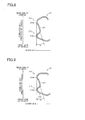
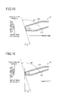
FIGS. 8 to 16 are respectively a cross-sectional view (FIG. 8 ) taken along the line VIII-VIII ofFIG. 6(b) , a cross-sectional view (FIG. 9 ) taken along the line IX-IX ofFIG. 6(b) , a cross-sectional view (FIG. 10 ) taken along the line X-X ofFIG. 6(b) , a cross-sectional view (FIG. 11 ) taken along the line XI-XI ofFIG. 6(b) , a cross-sectional view (FIG. 12 ) taken along the line XII-XII ofFIG. 6(b) , a cross-sectional view (FIG. 13 ) taken along the line XIII-XIII ofFIG. 6(b) , a cross-sectional view (FIG. 14 ) taken along the line XIV-XIV ofFIG. 6(b) , a cross-sectional view (FIG. 15 ) taken along the line XV-XV ofFIG. 6(b) , and a cross-sectional view (FIG. 16 ) taken along the line XVI-XVI ofFIG. 6(b) .FIGS. 8 to 13 are cross-sectional views illustrating the upper portion of the seat back right-hand side member 21 in the longitudinal direction thereof.FIGS. 14 to 16 are cross-sectional views of thebelt guide portion 27. - As illustrated in
FIGS. 8 to 11 , similarly to the center portion of the seat back right-hand side member 21 illustrated inFIG. 7 , also the upper portion of the seat back right-hand side member 21 includes: the side memberside wall portion 211 formed into a straight portion at substantially the center portion thereof in the fore-and-aft direction of the vehicle; the side memberfront wall portion 212 formed on the front side of the vehicle (lower side ofFIG. 8, 9 ,10, or 11 ) with respect to the side memberside wall portion 211; and the side memberrear wall portion 213 formed on the rear side of the vehicle (upper side ofFIG. 8, 9 ,10, or 11 ) with respect to the side memberside wall portion 211. Further, thefront projecting portion 212a is formed in the side memberfront wall portion 212, and therear projecting portion 213a is formed in the side memberrear wall portion 213. The front projectingportion 212a has the projecting amount larger than the projecting amount of therear projecting portion 213a. Note that, thesecond recess 21 d is formed in the seat back right-hand side member 21 at a position in cross-section illustrated inFIGS. 12 and13 , and hence the side memberside wall portion 211, thefront projecting portion 212a, and therear projecting portion 213a are not shown inFIGS. 12 and13 . - Further, similarly to the side member
side wall portion 211 illustrated inFIG. 7 , the side memberside wall portion 211 illustrated inFIGS. 8 to 11 is inclined at the angle α with respect to the fore-and-aft direction of the vehicle. The side memberside wall portion 211 is formed continuously as illustrated inFIGS. 7 to 11 . That is, a side wall, which is inclined at the angle α with respect to the fore-and-aft direction of the vehicle so as to be inclined inward from the outer side of the vehicle as extending from the rear side of the vehicle to the front side of the vehicle, is formed continuously in the seat back right-hand side member 21 along the longitudinal direction of the seat back right-hand side member 21. - Further, the
front projecting portion 212a and therear projecting portion 213a illustratedFIGS. 7 to 11 are formed continuously. That is, a ridge formed by thefront projecting portion 212a is formed continuously on the front side of the vehicle with respect to the side memberside wall portion 211 along the longitudinal direction of the seat back right-hand side member 21, and a ridge formed by therear projecting portion 213a is formed continuously on the rear side of the vehicle with respect to the side memberside wall portion 211 along the longitudinal direction of the seat back right-hand side member 21. The ridge formed on the front side of the vehicle with respect to the side memberside wall portion 211 has a projecting amount larger than a projecting amount of the ridge formed on the rear side of the vehicle with respect to the side memberside wall portion 211. - Further, as is apparent from
FIGS. 14 to 16 , thebelt guide portion 27 includes: a belt guideside wall portion 271 having a surface inclined at the angle α with respect to the fore-and-aft direction of the vehicle; a belt guidefront wall portion 272 extending from the front side of the vehicle with respect to the belt guideside wall portion 271 to the inner side of the seat back 40; and a belt guiderear wall portion 273 extending from the rear side of the vehicle with respect to the belt guideside wall portion 271 to the inner side of the seat back 40. The belt guidefront wall portion 272 and the belt guiderear wall portion 273 are orthogonal to the fore-and-aft direction of the vehicle at positions illustrated inFIG. 14 . However, at positions illustrated inFIGS. 15 and 16 , that is, in the upper portion of thebelt guide portion 27, the belt guidefront wall portion 272 and the belt guiderear wall portion 273 obliquely cross the fore-and-aft direction of the vehicle at the angle α with respect to the fore-and-aft direction of the vehicle. - Note that, according to this embodiment, it is preferred that the side member
side wall portion 211 formed in the seat back right-hand side member 21, and the belt guideside wall portion 271 formed in thebelt guide portion 27 be formed on the same plane. - The above-mentioned angle α corresponds to an angle formed by the fore-and-aft direction of the vehicle and a direction of application of the tension of the
seat belt 29 on thebelt guide portion 27, the tension of theseat belt 29 being caused when the occupant held by theseat belt 29 is thrust to the front side of the vehicle by an inertial force at the time of sudden braking of the vehicle. In other words, a direction inclined at the angle α with respect to the fore-and-aft direction of the vehicle corresponds to the direction of application of the tension of theseat belt 29 on thebelt guide portion 27. - According to this embodiment, the occupant is held by the
seat belt 29. Theseat belt 29 passes, via thebelt guide portion 27 situated near a right shoulder of the occupant, the tongue plate fixed to thebuckle 70 situated near a left lower back of the occupant. Therefore, the occupant is held by the seat belt that is slung from an upper right side to a lower left side of an upper part of his/her body. In a case where theseat belt 29 thus holding the occupant is pulled by the occupant to the front side of the vehicle, theseat belt 29 is pulled so as to extend obliquely with respect to the fore-and-aft direction of the vehicle when viewed from above. Accordingly, the direction of application of the tension of theseat belt 29 on thebelt guide portion 27 is inclined with respect to the fore-and-aft direction of the vehicle. This inclination angle is represented by α in this embodiment. -
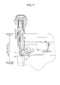
FIG. 17 is a top view of thebelt guide portion 27. As illustrated inFIG. 17 , an extending direction of acrest portion 275 connecting between an upper end of the belt guidefront wall portion 272 and an upper end of the belt guiderear wall portion 273 obliquely crosses the fore-and-aft direction of the vehicle at the angle α. Further, aguide frame 274 for allowing the seat belt to pass therethrough is fixed to thebelt guide portion 27. A direction of the guide frame is inclined at the angle α with respect to the fore-and-aft direction of the vehicle. - Further, according to this embodiment, the seat back right-
hand side member 21 and thebelt guide portion 27 are integrally molded from one sheet of steel plate by a die quenching process. That is, one sheet of steel plate is pressed to integrally mold the seat back right-hand side member 21 and thebelt guide portion 27, and after molding, dies and a molded product are held in contact with each other in a die assembly. Thus, the molded product is quenched. Through the quenching, the molded product is hardened. Then, after cooling, the molded product is taken out of the die assembly. - In the seat frame configured as described above, while the occupant seated on the seat is held by the
seat belt 29, when, for example, the vehicle is braked suddenly, the occupant is thrust to the front side of the vehicle. Accordingly, theseat belt 29 is pulled, and thus theseat belt 29 generates the tension. The tension of theseat belt 29 is applied onto thebelt guide portion 27 over which theseat belt 29 is hung, and the tension of theseat belt 29 is also applied on the seat back right-hand side member 21 to which thebelt guide portion 27 is fixed. As described above, the direction of application of the tension of theseat belt 29 on the seat back right-hand side member 21 and thebelt guide portion 27 is inclined at the angle α with respect to the fore-and-aft direction of the vehicle. - The seat back right-
hand side member 21 according to this embodiment includes the side memberside wall portion 211 that is inclined at the angle α with respect to the fore-and-aft direction of the vehicle. Further, also thebelt guide portion 27 includes the belt guideside wall portion 271 that is inclined at the angle α with respect to the fore-and-aft direction of the vehicle. That is, theside wall portions seat belt 29 on thebelt guide portion 27. More specifically, theside wall portions belt guide portion 29 and formed continuously along the longitudinal direction of the seat back right-hand side member 21 (that is, formed in parallel to the direction of application of the tension of the seat belt and to the longitudinal direction of the seat back right-hand side member 21). By virtue of this configuration, when the tension of theseat belt 29 is applied onto thebelt guide portion 27, the side memberside wall portion 211 and the belt guideside wall portion 271 effectively function as reinforcing portions against the tension, because the side memberside wall portion 211 and the belt guideside wall portion 271 are provided parallel to the tension. As a result, the rigidity with respect to the tension of theseat belt 29 can be increased. Accordingly, it is possible to provide the seat frame in which rigidity with respect to the tension of theseat belt 29 is increased. - Further, the seat back right-
hand side member 21 and thebelt guide portion 27 are formed of one sheet of steel plate. Accordingly, the number of components is reduced, and thus it is possible to reduce a manufacturing cost of the seat frame. - Further, as is apparent from
FIGS. 7 to 13 , the seat back right-hand side member 21 has an open cross-sectional shape. In a case where the seat back right-hand side member 21 has a closed cross-sectional shape, it is necessary to superpose a plurality of sheets of steel plate and join the sheets of steel plate together by wending or the like. However, when the seat back right-hand side member 21 has an open cross-sectional shape, the seat back right-hand side member 21 can be processed using one sheet of steel plate. Therefore, man-hours for welding the plurality of sheets of steel plate are reduced. Accordingly, it is possible to further reduce the manufacturing cost of the seat frame. - Further, the
front projecting portion 212a forms the ridge formed on the front side of the vehicle with respect to the side memberside wall portion 211 along the longitudinal direction of the seat back right-hand side member 21. The ridge prevents the seat back right-hand side member 21 from buckling and deforming when the seat back right-hand side member 21 is pulled to the front side of the vehicle by the tension of theseat belt 29. Further, therear projecting portion 213a forms the ridge formed on the rear side of the vehicle with respect to the side memberside wall portion 211 along the longitudinal direction of the seat back right-hand side member 21. The ridge reinforces the seat back right-hand side member 21, and thus prevents the seat back right-hand side member 21 from buckling and deforming when the seat back right-hand side member 21 is pulled to the rear side of the vehicle. - Further, the
front projecting portion 212a has the projecting amount larger than the projecting amount of therear projecting portion 213a. Therefore, when the seat back right-hand side member 21 is pulled to the front side of the vehicle by theseat belt 29 with a large force, for example, at the time of sudden braking of the vehicle, the seat back right-hand side member 21 is more effectively prevented from buckling and deforming. - Further, also the
belt guide portion 27 includes the belt guideside wall portion 271 formed in parallel to the direction of application of the tension of theseat belt 29 on thebelt guide portion 27. Accordingly, against the tension of the seat belt, the belt guideside wall portion 271 effectively functions as a reinforcing portion. Thus, rigidity with respect to the tension of the seat belt is further increased. - Further, a portion of the belt guide
front wall portion 272 and a portion of the belt guiderear wall portion 273 in the upper portion of thebelt guide portion 27 are orthogonal to the direction of application of the tension of theseat belt 29 on thebelt guide portion 27. Accordingly, when theseat belt 29 generates the tension while theseat belt 29 is hung over thebelt guide portion 27, theseat belt 29 is prevented from slipping off. Thus, the tension of theseat belt 29 is correctly applied in the direction along the belt guideside wall portion 271 and the side memberside wall portion 211. - Further, the seat back right-
hand side member 21 and thebelt guide portion 27 are integrally produced by die quenching, and hence it is possible to increase strength of the seat back right-hand side member 21 and thebelt guide portion 27. - Further, the
lower cross member 24 is set to have the vertical length larger than its widthwise length in cross-section. Accordingly, thefirst recess 21 c, which is formed in the seat back right-hand side member 21 in order to fix thelower cross member 24, is formed into a vertically elongated shape. As described above, thefirst recess 21 c can be formed into a vertically elongated shape, and thus an area of the recess formed in the seat back right-hand side member 21 is correspondingly reduced. Consequently, it is possible to prevent reduction in strength of the seat back right-hand side member that is accompanied with formation of the recess.
Claims (9)
- A seat frame, comprising:a seat cushion frame for supporting a seat cushion of a seat of a vehicle; anda seat back frame to which a seat belt retaining member is coupled, the seat back frame being coupled to the seat cushion frame and supporting a seat back of the seat, the seat belt retaining member retaining one end of a seat belt for holding an occupant seated on the seat,the seat back frame comprising:a first side member and a second side member each formed into an elongated shape along an up-and-down direction of the seat back so as to support each side portion of the seat back; anda belt guide portion on which tension of the seat belt is applied when the seat belt is pulled, the belt guide portion being formed in an upper portion of the first side member and guiding the seat belt having the one end retained by the seat belt retaining member,the first side member being formed of one sheet of steel plate and comprising:a side member side wall portion formed in parallel to a direction of application of the tension of the seat belt on the belt guide portion and formed continuously along a longitudinal direction of the first side member;a side member front wall portion formed on a front side of the vehicle with respect to the side member side wall portion; anda side member rear wall portion formed on a rear side of the vehicle with respect to the side member side wall portion,the first side member having an open cross-sectional shape.
- A seat frame according to claim 1, wherein:the side member front wall portion comprises a front projecting portion projecting to an outer side of the seat back with respect to the side member side wall portion;the side member rear wall portion comprises a rear projecting portion projecting to the outer side of the seat back with respect to the side member side wall portion;the front projecting portion and the rear projecting portion are formed continuously along the longitudinal direction of the first side member; andthe front projecting portion has a projecting amount larger than a projecting amount of the rear projecting portion.
- A seat frame according to claim 1 or 2, wherein the belt guide portion comprises:a belt guide side wall portion formed in parallel to the direction of application of the tension of the seat belt on the belt guide portion;a belt guide front wall portion formed on the front side of the vehicle with respect to the belt guide side wall portion so as to extend to an inner side of the seat back; anda belt guide rear wall portion formed on the rear side of the vehicle with respect to the belt guide side wall portion so as to extend to the inner side of the seat back.
- A seat frame according to claim 3, wherein the belt guide front wall portion and the belt guide rear wall portion each comprise a portion orthogonal to the direction of application of the tension of the seat belt on the belt guide portion.
- A seat frame according to any one of claims 1 to 4, wherein the first side member is produced by die quenching.
- A seat frame according to any one of claims 1 to 5, wherein:the seat back frame comprises a cross member for coupling the first side member and the second side member together; andthe cross member is set to have a vertical length larger than a widthwise length thereof in cross-section.
- A seat frame, comprising:a seat cushion frame for supporting a seat cushion of a seat of a vehicle; anda seat back frame to which a seat belt retaining member is coupled, the seat back frame being coupled to the seat cushion frame and supporting a seat back of the seat, the seat belt retaining member retaining one end of a seat belt for holding an occupant seated on the seat,the seat back frame comprising:a first side member and a second side member each formed into an elongated shape along an up-and-down direction of the seat back so as to support each side portion of the seat back; anda belt guide portion on which tension of the seat belt is applied when the seat belt is pulled, the belt guide portion being formed in an upper portion of the first side member and guiding the seat belt having the one end retained by the seat belt retaining member,the first side member being formed of one sheet of steel plate and comprising:a side member side wall portion formed so as to be inclined with respect to a fore-and-aft direction of the vehicle and formed continuously along a longitudinal direction of the first side member;a side member front wall portion formed on a front side of the vehicle with respect to the side member side wall portion; anda side member rear wall portion formed on a rear side of the vehicle with respect to the side member side wall portion,the first side member having an open cross-sectional shape.
- A seat frame according to claim 7, wherein the side member side wall portion is inclined inward from an outer side of the vehicle as extending from the rear side of the vehicle to the front side of the vehicle.
- A seat frame according to claim 8, wherein a direction of inclination of the side member side wall portion is parallel to the direction of application of the tension of the seat belt on the belt guide portion.
Applications Claiming Priority (2)
| Application Number | Priority Date | Filing Date | Title |
|---|---|---|---|
| JP2010248561A JP5768356B2 (en) | 2010-11-05 | 2010-11-05 | Vehicle seat frame |
| PCT/JP2011/075430 WO2012060440A1 (en) | 2010-11-05 | 2011-11-04 | Seat frame for vehicle |
Publications (3)
| Publication Number | Publication Date |
|---|---|
| EP2636558A1 true EP2636558A1 (en) | 2013-09-11 |
| EP2636558A4 EP2636558A4 (en) | 2015-11-04 |
| EP2636558B1 EP2636558B1 (en) | 2017-04-19 |
Family
ID=46024553
Family Applications (1)
| Application Number | Title | Priority Date | Filing Date |
|---|---|---|---|
| EP11838090.6A Not-in-force EP2636558B1 (en) | 2010-11-05 | 2011-11-04 | Seat frame for vehicle |
Country Status (5)
| Country | Link |
|---|---|
| US (1) | US9039094B2 (en) |
| EP (1) | EP2636558B1 (en) |
| JP (1) | JP5768356B2 (en) |
| CN (1) | CN203267825U (en) |
| WO (1) | WO2012060440A1 (en) |
Families Citing this family (25)
| Publication number | Priority date | Publication date | Assignee | Title |
|---|---|---|---|---|
| EP2483103A1 (en) * | 2009-10-02 | 2012-08-08 | Johnson Controls Technology Company | One-piece seat bottom chassis |
| JP5695870B2 (en) * | 2010-09-30 | 2015-04-08 | テイ・エス テック株式会社 | Vehicle seat |
| JP5799838B2 (en) * | 2012-02-01 | 2015-10-28 | トヨタ紡織株式会社 | Vehicle seat cushion frame |
| KR101398172B1 (en) * | 2012-04-24 | 2014-05-22 | 경북대학교 산학협력단 | Car Seat Belts |
| CN104487286A (en) * | 2012-07-23 | 2015-04-01 | 提爱思科技股份有限公司 | Seatbelt guide support, seat back frame, and seat device |
| DE102013003788B3 (en) * | 2012-11-30 | 2014-05-15 | Keiper Gmbh & Co. Kg | vehicle seat |
| US20150352982A1 (en) * | 2012-12-28 | 2015-12-10 | Ts Tech Co., Ltd. | Seat device |
| ITTO20130290A1 (en) * | 2013-04-10 | 2014-10-11 | Ruspa Officine S P A | SEAT FOR VEHICLE |
| JP6218324B2 (en) | 2014-01-29 | 2017-10-25 | 株式会社タチエス | Seat frame forming method for vehicle seat, seat frame and vehicle seat |
| US10227023B2 (en) * | 2015-03-31 | 2019-03-12 | Safran Seats Usa Llc | Energy absorbing brackets for passenger seats |
| JP6527418B2 (en) * | 2015-07-31 | 2019-06-05 | トヨタ紡織株式会社 | Vehicle seat |
| JP6565785B2 (en) * | 2016-04-28 | 2019-08-28 | トヨタ紡織株式会社 | Vehicle seat |
| JP6651981B2 (en) | 2016-05-19 | 2020-02-19 | トヨタ紡織株式会社 | Seat back frame |
| JP2017210084A (en) * | 2016-05-25 | 2017-11-30 | トヨタ紡織株式会社 | Back frame structure of vehicular seat |
| BR112019005879B1 (en) * | 2016-09-27 | 2022-12-20 | Proma S.P.A. | SEAT FOR VEHICLES HAVING COUPLING EDGE |
| JP6874360B2 (en) * | 2016-12-21 | 2021-05-19 | トヨタ紡織株式会社 | Vehicle seat |
| US10086792B1 (en) * | 2017-03-30 | 2018-10-02 | Ts Tech Co., Ltd. | Vehicle Seat |
| JP2018192934A (en) * | 2017-05-18 | 2018-12-06 | トヨタ紡織株式会社 | Back frame of seat for vehicle |
| JP6979319B2 (en) * | 2017-09-25 | 2021-12-08 | 株式会社タチエス | Vehicle seat |
| JP6785206B2 (en) * | 2017-09-25 | 2020-11-18 | 株式会社タチエス | Vehicle seat |
| JP7103587B2 (en) * | 2018-12-27 | 2022-07-20 | 日本発條株式会社 | Vehicle seat |
| KR102284175B1 (en) * | 2019-12-20 | 2021-07-30 | 광우알엔에이 주식회사 | Seat back frame for a vehicle and manufacturing method thereof |
| US11827175B2 (en) | 2020-12-30 | 2023-11-28 | Joyson Safety Systems Acquisition Llc | Adapting shoulder anchor for seatbelt |
| WO2023076480A1 (en) * | 2021-10-27 | 2023-05-04 | Magna Seating Inc. | Multi-function rear seat structure with stow to floor |
| KR20230089269A (en) * | 2021-12-13 | 2023-06-20 | 주식회사 포스코 | Seat back |
Family Cites Families (20)
| Publication number | Priority date | Publication date | Assignee | Title |
|---|---|---|---|---|
| DE3624295A1 (en) | 1986-07-18 | 1988-01-21 | Keiper Recaro Gmbh Co | BACKREST FRAME FOR SEATS, ESPECIALLY FOR MOTOR VEHICLE SEATS |
| FR2736312B1 (en) * | 1995-07-03 | 1997-09-19 | Faure Bertrand Equipements Sa | BACKREST FOR VEHICLE SEAT AND SEAT COMPRISING SUCH A BACKREST |
| US5722731A (en) * | 1995-10-25 | 1998-03-03 | Chang; Chung L. | Vehicle seat and seat belt arrangement |
| DE19603946C2 (en) * | 1996-02-05 | 1998-06-04 | Daimler Benz Ag | Vehicle seat |
| JPH09254689A (en) * | 1996-03-22 | 1997-09-30 | Toyota Motor Corp | Seat back frame that allows the seat to lean forward |
| FR2750374B1 (en) * | 1996-06-28 | 1998-09-18 | Ecia Equip Composants Ind Auto | SEAT FOR A MOTOR VEHICLE WITH IMPROVED BACKREST |
| FR2777518B1 (en) * | 1998-04-17 | 2000-06-16 | Faure Bertrand Equipements Sa | MOTOR VEHICLE SEAT BACKREST |
| JP2001149176A (en) * | 1999-11-29 | 2001-06-05 | Tachi S Co Ltd | Seat back frame structure |
| JP2002283893A (en) * | 2001-03-23 | 2002-10-03 | Johnson Controls Automotive Systems Corp | Seat back frame in vehicular seat |
| JP2002283892A (en) | 2001-03-23 | 2002-10-03 | Johnson Controls Automotive Systems Corp | Seat back frame in vehicular seat |
| JP2002283891A (en) * | 2001-03-23 | 2002-10-03 | Johnson Controls Automotive Systems Corp | Seat back frame in vehicular seat |
| US6767055B1 (en) * | 2002-03-11 | 2004-07-27 | Bostrom Seating, Inc. | Vehicle seat frame and belt assembly |
| JP2005145168A (en) * | 2003-11-13 | 2005-06-09 | Aisin Takaoka Ltd | Method of manufacturing vehicle skeleton member |
| JP4643480B2 (en) * | 2006-03-23 | 2011-03-02 | トヨタ自動車株式会社 | Vehicle seat back frame |
| US7497521B2 (en) * | 2006-08-30 | 2009-03-03 | Honda Motor Co., Ltd | Seat belt retractor mounting system |
| JP5082795B2 (en) | 2007-11-20 | 2012-11-28 | アイシン精機株式会社 | Vehicle seat frame |
| JP5608930B2 (en) * | 2009-08-21 | 2014-10-22 | 株式会社デルタツーリング | Vehicle seat |
| EP2498644A4 (en) * | 2009-11-12 | 2015-12-09 | Johnson Controls Tech Co | ONE-PIECE SEAT BACK FOLDING ASSEMBLY AND METHOD OF MANUFACTURING SAME |
| JP2011132727A (en) | 2009-12-24 | 2011-07-07 | Aisin Seiki Co Ltd | Catching-in detector of opening/closing body |
| JP5625831B2 (en) * | 2010-12-01 | 2014-11-19 | アイシン精機株式会社 | Seat frame |
-
2010
- 2010-11-05 JP JP2010248561A patent/JP5768356B2/en not_active Expired - Fee Related
-
2011
- 2011-11-04 EP EP11838090.6A patent/EP2636558B1/en not_active Not-in-force
- 2011-11-04 WO PCT/JP2011/075430 patent/WO2012060440A1/en not_active Ceased
- 2011-11-04 CN CN2011900008520U patent/CN203267825U/en not_active Expired - Fee Related
- 2011-11-04 US US13/883,305 patent/US9039094B2/en not_active Expired - Fee Related
Also Published As
| Publication number | Publication date |
|---|---|
| JP5768356B2 (en) | 2015-08-26 |
| EP2636558B1 (en) | 2017-04-19 |
| EP2636558A4 (en) | 2015-11-04 |
| CN203267825U (en) | 2013-11-06 |
| WO2012060440A1 (en) | 2012-05-10 |
| JP2012096759A (en) | 2012-05-24 |
| US9039094B2 (en) | 2015-05-26 |
| US20130221725A1 (en) | 2013-08-29 |
Similar Documents
| Publication | Publication Date | Title |
|---|---|---|
| EP2636558B1 (en) | Seat frame for vehicle | |
| US8882195B2 (en) | Base for a person's seat | |
| DE102014202562B4 (en) | FRAME STRUCTURE OF A VEHICLE SEAT | |
| EP2103480B1 (en) | Seat apparatus for vehicle | |
| US7040708B2 (en) | Vehicle seat | |
| US10144326B2 (en) | Vehicle seat | |
| US9586508B2 (en) | Vehicle seat | |
| CN102328603B (en) | Support structure of vehicle seat frame | |
| JP2002283891A (en) | Seat back frame in vehicular seat | |
| US10889207B2 (en) | Longitudinal adjuster and vehicle seat | |
| JP2004189208A (en) | Front side rail rear part reinforcing structure of automobile | |
| US10166896B2 (en) | Seat belt attachment structure for off-road vehicle | |
| CN109715438B (en) | Guide rail and vehicle seat | |
| MX2015002728A (en) | Vehicle seat. | |
| US9725021B2 (en) | Vehicle seat, and seat frame for vehicle seat | |
| JP6169134B2 (en) | Vehicle seat rail | |
| CN109552125B (en) | Vehicle seat | |
| DE602004002247T2 (en) | Vehicle with a seat belt device | |
| KR101394919B1 (en) | Vehicle seat, particularly motor vehicle seat | |
| JP5433847B2 (en) | Vehicle seat back frame structure | |
| EP2544925B1 (en) | Safety belt system in a vehicle | |
| US8820842B2 (en) | Vehicle seat with a support structure | |
| CN212243065U (en) | vehicle seat | |
| JP3928242B2 (en) | Vehicle seat belt device | |
| CN212073812U (en) | vehicle seat |
Legal Events
| Date | Code | Title | Description |
|---|---|---|---|
| PUAI | Public reference made under article 153(3) epc to a published international application that has entered the european phase |
Free format text: ORIGINAL CODE: 0009012 |
|
| 17P | Request for examination filed |
Effective date: 20130520 |
|
| AK | Designated contracting states |
Kind code of ref document: A1 Designated state(s): AL AT BE BG CH CY CZ DE DK EE ES FI FR GB GR HR HU IE IS IT LI LT LU LV MC MK MT NL NO PL PT RO RS SE SI SK SM TR |
|
| DAX | Request for extension of the european patent (deleted) | ||
| RIN1 | Information on inventor provided before grant (corrected) |
Inventor name: GOTO, NAOKI Inventor name: YAMADA, YUKIFUMI |
|
| REG | Reference to a national code |
Ref country code: DE Ref legal event code: R079 Ref document number: 602011037221 Country of ref document: DE Free format text: PREVIOUS MAIN CLASS: B60N0002440000 Ipc: B60N0002480000 |
|
| RA4 | Supplementary search report drawn up and despatched (corrected) |
Effective date: 20151002 |
|
| RIC1 | Information provided on ipc code assigned before grant |
Ipc: B60N 2/68 20060101ALI20150928BHEP Ipc: B60N 2/64 20060101ALI20150928BHEP Ipc: B60N 2/48 20060101AFI20150928BHEP |
|
| GRAP | Despatch of communication of intention to grant a patent |
Free format text: ORIGINAL CODE: EPIDOSNIGR1 |
|
| INTG | Intention to grant announced |
Effective date: 20160621 |
|
| GRAJ | Information related to disapproval of communication of intention to grant by the applicant or resumption of examination proceedings by the epo deleted |
Free format text: ORIGINAL CODE: EPIDOSDIGR1 |
|
| GRAP | Despatch of communication of intention to grant a patent |
Free format text: ORIGINAL CODE: EPIDOSNIGR1 |
|
| INTC | Intention to grant announced (deleted) | ||
| INTG | Intention to grant announced |
Effective date: 20161014 |
|
| GRAS | Grant fee paid |
Free format text: ORIGINAL CODE: EPIDOSNIGR3 |
|
| GRAJ | Information related to disapproval of communication of intention to grant by the applicant or resumption of examination proceedings by the epo deleted |
Free format text: ORIGINAL CODE: EPIDOSDIGR1 |
|
| GRAL | Information related to payment of fee for publishing/printing deleted |
Free format text: ORIGINAL CODE: EPIDOSDIGR3 |
|
| GRAR | Information related to intention to grant a patent recorded |
Free format text: ORIGINAL CODE: EPIDOSNIGR71 |
|
| GRAA | (expected) grant |
Free format text: ORIGINAL CODE: 0009210 |
|
| INTC | Intention to grant announced (deleted) | ||
| INTG | Intention to grant announced |
Effective date: 20170308 |
|
| AK | Designated contracting states |
Kind code of ref document: B1 Designated state(s): AL AT BE BG CH CY CZ DE DK EE ES FI FR GB GR HR HU IE IS IT LI LT LU LV MC MK MT NL NO PL PT RO RS SE SI SK SM TR |
|
| REG | Reference to a national code |
Ref country code: GB Ref legal event code: FG4D |
|
| REG | Reference to a national code |
Ref country code: CH Ref legal event code: EP |
|
| REG | Reference to a national code |
Ref country code: AT Ref legal event code: REF Ref document number: 885609 Country of ref document: AT Kind code of ref document: T Effective date: 20170515 |
|
| REG | Reference to a national code |
Ref country code: IE Ref legal event code: FG4D |
|
| REG | Reference to a national code |
Ref country code: DE Ref legal event code: R096 Ref document number: 602011037221 Country of ref document: DE |
|
| REG | Reference to a national code |
Ref country code: NL Ref legal event code: MP Effective date: 20170419 |
|
| REG | Reference to a national code |
Ref country code: LT Ref legal event code: MG4D |
|
| REG | Reference to a national code |
Ref country code: AT Ref legal event code: MK05 Ref document number: 885609 Country of ref document: AT Kind code of ref document: T Effective date: 20170419 |
|
| REG | Reference to a national code |
Ref country code: FR Ref legal event code: PLFP Year of fee payment: 7 |
|
| PG25 | Lapsed in a contracting state [announced via postgrant information from national office to epo] |
Ref country code: NL Free format text: LAPSE BECAUSE OF FAILURE TO SUBMIT A TRANSLATION OF THE DESCRIPTION OR TO PAY THE FEE WITHIN THE PRESCRIBED TIME-LIMIT Effective date: 20170419 |
|
| PG25 | Lapsed in a contracting state [announced via postgrant information from national office to epo] |
Ref country code: NO Free format text: LAPSE BECAUSE OF FAILURE TO SUBMIT A TRANSLATION OF THE DESCRIPTION OR TO PAY THE FEE WITHIN THE PRESCRIBED TIME-LIMIT Effective date: 20170719 Ref country code: AT Free format text: LAPSE BECAUSE OF FAILURE TO SUBMIT A TRANSLATION OF THE DESCRIPTION OR TO PAY THE FEE WITHIN THE PRESCRIBED TIME-LIMIT Effective date: 20170419 Ref country code: FI Free format text: LAPSE BECAUSE OF FAILURE TO SUBMIT A TRANSLATION OF THE DESCRIPTION OR TO PAY THE FEE WITHIN THE PRESCRIBED TIME-LIMIT Effective date: 20170419 Ref country code: LT Free format text: LAPSE BECAUSE OF FAILURE TO SUBMIT A TRANSLATION OF THE DESCRIPTION OR TO PAY THE FEE WITHIN THE PRESCRIBED TIME-LIMIT Effective date: 20170419 Ref country code: HR Free format text: LAPSE BECAUSE OF FAILURE TO SUBMIT A TRANSLATION OF THE DESCRIPTION OR TO PAY THE FEE WITHIN THE PRESCRIBED TIME-LIMIT Effective date: 20170419 Ref country code: GR Free format text: LAPSE BECAUSE OF FAILURE TO SUBMIT A TRANSLATION OF THE DESCRIPTION OR TO PAY THE FEE WITHIN THE PRESCRIBED TIME-LIMIT Effective date: 20170720 Ref country code: ES Free format text: LAPSE BECAUSE OF FAILURE TO SUBMIT A TRANSLATION OF THE DESCRIPTION OR TO PAY THE FEE WITHIN THE PRESCRIBED TIME-LIMIT Effective date: 20170419 |
|
| REG | Reference to a national code |
Ref country code: DE Ref legal event code: R079 Ref document number: 602011037221 Country of ref document: DE Free format text: PREVIOUS MAIN CLASS: B60N0002480000 Ipc: B60N0002800000 |
|
| PG25 | Lapsed in a contracting state [announced via postgrant information from national office to epo] |
Ref country code: RS Free format text: LAPSE BECAUSE OF FAILURE TO SUBMIT A TRANSLATION OF THE DESCRIPTION OR TO PAY THE FEE WITHIN THE PRESCRIBED TIME-LIMIT Effective date: 20170419 Ref country code: IS Free format text: LAPSE BECAUSE OF FAILURE TO SUBMIT A TRANSLATION OF THE DESCRIPTION OR TO PAY THE FEE WITHIN THE PRESCRIBED TIME-LIMIT Effective date: 20170819 Ref country code: PL Free format text: LAPSE BECAUSE OF FAILURE TO SUBMIT A TRANSLATION OF THE DESCRIPTION OR TO PAY THE FEE WITHIN THE PRESCRIBED TIME-LIMIT Effective date: 20170419 Ref country code: BG Free format text: LAPSE BECAUSE OF FAILURE TO SUBMIT A TRANSLATION OF THE DESCRIPTION OR TO PAY THE FEE WITHIN THE PRESCRIBED TIME-LIMIT Effective date: 20170719 Ref country code: SE Free format text: LAPSE BECAUSE OF FAILURE TO SUBMIT A TRANSLATION OF THE DESCRIPTION OR TO PAY THE FEE WITHIN THE PRESCRIBED TIME-LIMIT Effective date: 20170419 Ref country code: LV Free format text: LAPSE BECAUSE OF FAILURE TO SUBMIT A TRANSLATION OF THE DESCRIPTION OR TO PAY THE FEE WITHIN THE PRESCRIBED TIME-LIMIT Effective date: 20170419 |
|
| REG | Reference to a national code |
Ref country code: DE Ref legal event code: R097 Ref document number: 602011037221 Country of ref document: DE |
|
| PG25 | Lapsed in a contracting state [announced via postgrant information from national office to epo] |
Ref country code: DK Free format text: LAPSE BECAUSE OF FAILURE TO SUBMIT A TRANSLATION OF THE DESCRIPTION OR TO PAY THE FEE WITHIN THE PRESCRIBED TIME-LIMIT Effective date: 20170419 Ref country code: EE Free format text: LAPSE BECAUSE OF FAILURE TO SUBMIT A TRANSLATION OF THE DESCRIPTION OR TO PAY THE FEE WITHIN THE PRESCRIBED TIME-LIMIT Effective date: 20170419 Ref country code: RO Free format text: LAPSE BECAUSE OF FAILURE TO SUBMIT A TRANSLATION OF THE DESCRIPTION OR TO PAY THE FEE WITHIN THE PRESCRIBED TIME-LIMIT Effective date: 20170419 Ref country code: CZ Free format text: LAPSE BECAUSE OF FAILURE TO SUBMIT A TRANSLATION OF THE DESCRIPTION OR TO PAY THE FEE WITHIN THE PRESCRIBED TIME-LIMIT Effective date: 20170419 Ref country code: SK Free format text: LAPSE BECAUSE OF FAILURE TO SUBMIT A TRANSLATION OF THE DESCRIPTION OR TO PAY THE FEE WITHIN THE PRESCRIBED TIME-LIMIT Effective date: 20170419 |
|
| PLBE | No opposition filed within time limit |
Free format text: ORIGINAL CODE: 0009261 |
|
| STAA | Information on the status of an ep patent application or granted ep patent |
Free format text: STATUS: NO OPPOSITION FILED WITHIN TIME LIMIT |
|
| PG25 | Lapsed in a contracting state [announced via postgrant information from national office to epo] |
Ref country code: IT Free format text: LAPSE BECAUSE OF FAILURE TO SUBMIT A TRANSLATION OF THE DESCRIPTION OR TO PAY THE FEE WITHIN THE PRESCRIBED TIME-LIMIT Effective date: 20170419 Ref country code: SM Free format text: LAPSE BECAUSE OF FAILURE TO SUBMIT A TRANSLATION OF THE DESCRIPTION OR TO PAY THE FEE WITHIN THE PRESCRIBED TIME-LIMIT Effective date: 20170419 |
|
| 26N | No opposition filed |
Effective date: 20180122 |
|
| PG25 | Lapsed in a contracting state [announced via postgrant information from national office to epo] |
Ref country code: SI Free format text: LAPSE BECAUSE OF FAILURE TO SUBMIT A TRANSLATION OF THE DESCRIPTION OR TO PAY THE FEE WITHIN THE PRESCRIBED TIME-LIMIT Effective date: 20170419 |
|
| PG25 | Lapsed in a contracting state [announced via postgrant information from national office to epo] |
Ref country code: MC Free format text: LAPSE BECAUSE OF FAILURE TO SUBMIT A TRANSLATION OF THE DESCRIPTION OR TO PAY THE FEE WITHIN THE PRESCRIBED TIME-LIMIT Effective date: 20170419 |
|
| GBPC | Gb: european patent ceased through non-payment of renewal fee |
Effective date: 20171104 |
|
| PG25 | Lapsed in a contracting state [announced via postgrant information from national office to epo] |
Ref country code: LI Free format text: LAPSE BECAUSE OF NON-PAYMENT OF DUE FEES Effective date: 20171130 Ref country code: CH Free format text: LAPSE BECAUSE OF NON-PAYMENT OF DUE FEES Effective date: 20171130 |
|
| PG25 | Lapsed in a contracting state [announced via postgrant information from national office to epo] |
Ref country code: LU Free format text: LAPSE BECAUSE OF NON-PAYMENT OF DUE FEES Effective date: 20171104 |
|
| REG | Reference to a national code |
Ref country code: BE Ref legal event code: MM Effective date: 20171130 |
|
| REG | Reference to a national code |
Ref country code: IE Ref legal event code: MM4A |
|
| REG | Reference to a national code |
Ref country code: FR Ref legal event code: PLFP Year of fee payment: 8 |
|
| PG25 | Lapsed in a contracting state [announced via postgrant information from national office to epo] |
Ref country code: MT Free format text: LAPSE BECAUSE OF NON-PAYMENT OF DUE FEES Effective date: 20171104 |
|
| PG25 | Lapsed in a contracting state [announced via postgrant information from national office to epo] |
Ref country code: IE Free format text: LAPSE BECAUSE OF NON-PAYMENT OF DUE FEES Effective date: 20171104 |
|
| PG25 | Lapsed in a contracting state [announced via postgrant information from national office to epo] |
Ref country code: BE Free format text: LAPSE BECAUSE OF NON-PAYMENT OF DUE FEES Effective date: 20171130 Ref country code: GB Free format text: LAPSE BECAUSE OF NON-PAYMENT OF DUE FEES Effective date: 20171104 |
|
| PG25 | Lapsed in a contracting state [announced via postgrant information from national office to epo] |
Ref country code: HU Free format text: LAPSE BECAUSE OF FAILURE TO SUBMIT A TRANSLATION OF THE DESCRIPTION OR TO PAY THE FEE WITHIN THE PRESCRIBED TIME-LIMIT; INVALID AB INITIO Effective date: 20111104 |
|
| PG25 | Lapsed in a contracting state [announced via postgrant information from national office to epo] |
Ref country code: CY Free format text: LAPSE BECAUSE OF NON-PAYMENT OF DUE FEES Effective date: 20170419 |
|
| PGFP | Annual fee paid to national office [announced via postgrant information from national office to epo] |
Ref country code: FR Payment date: 20190913 Year of fee payment: 9 |
|
| PG25 | Lapsed in a contracting state [announced via postgrant information from national office to epo] |
Ref country code: MK Free format text: LAPSE BECAUSE OF FAILURE TO SUBMIT A TRANSLATION OF THE DESCRIPTION OR TO PAY THE FEE WITHIN THE PRESCRIBED TIME-LIMIT Effective date: 20170419 |
|
| PGFP | Annual fee paid to national office [announced via postgrant information from national office to epo] |
Ref country code: DE Payment date: 20191022 Year of fee payment: 9 |
|
| PG25 | Lapsed in a contracting state [announced via postgrant information from national office to epo] |
Ref country code: TR Free format text: LAPSE BECAUSE OF FAILURE TO SUBMIT A TRANSLATION OF THE DESCRIPTION OR TO PAY THE FEE WITHIN THE PRESCRIBED TIME-LIMIT Effective date: 20170419 |
|
| PG25 | Lapsed in a contracting state [announced via postgrant information from national office to epo] |
Ref country code: PT Free format text: LAPSE BECAUSE OF FAILURE TO SUBMIT A TRANSLATION OF THE DESCRIPTION OR TO PAY THE FEE WITHIN THE PRESCRIBED TIME-LIMIT Effective date: 20170419 |
|
| PG25 | Lapsed in a contracting state [announced via postgrant information from national office to epo] |
Ref country code: AL Free format text: LAPSE BECAUSE OF FAILURE TO SUBMIT A TRANSLATION OF THE DESCRIPTION OR TO PAY THE FEE WITHIN THE PRESCRIBED TIME-LIMIT Effective date: 20170419 |
|
| REG | Reference to a national code |
Ref country code: DE Ref legal event code: R119 Ref document number: 602011037221 Country of ref document: DE |
|
| PG25 | Lapsed in a contracting state [announced via postgrant information from national office to epo] |
Ref country code: FR Free format text: LAPSE BECAUSE OF NON-PAYMENT OF DUE FEES Effective date: 20201130 |
|
| PG25 | Lapsed in a contracting state [announced via postgrant information from national office to epo] |
Ref country code: DE Free format text: LAPSE BECAUSE OF NON-PAYMENT OF DUE FEES Effective date: 20210601 |