EP2636481A2 - Apparatus having cup attaching unit - Google Patents
Apparatus having cup attaching unit Download PDFInfo
- Publication number
- EP2636481A2 EP2636481A2 EP13001140.6A EP13001140A EP2636481A2 EP 2636481 A2 EP2636481 A2 EP 2636481A2 EP 13001140 A EP13001140 A EP 13001140A EP 2636481 A2 EP2636481 A2 EP 2636481A2
- Authority
- EP
- European Patent Office
- Prior art keywords
- lens
- unit
- cup
- attaching
- processing
- Prior art date
- Legal status (The legal status is an assumption and is not a legal conclusion. Google has not performed a legal analysis and makes no representation as to the accuracy of the status listed.)
- Granted
Links
Images





Classifications
-
- B—PERFORMING OPERATIONS; TRANSPORTING
- B29—WORKING OF PLASTICS; WORKING OF SUBSTANCES IN A PLASTIC STATE IN GENERAL
- B29D—PRODUCING PARTICULAR ARTICLES FROM PLASTICS OR FROM SUBSTANCES IN A PLASTIC STATE
- B29D11/00—Producing optical elements, e.g. lenses or prisms
- B29D11/00932—Combined cutting and grinding thereof
- B29D11/00942—Combined cutting and grinding thereof where the lens material is mounted in a support for mounting onto a cutting device, e.g. a lathe, and where the support is of machinable material, e.g. plastics
-
- B—PERFORMING OPERATIONS; TRANSPORTING
- B24—GRINDING; POLISHING
- B24B—MACHINES, DEVICES, OR PROCESSES FOR GRINDING OR POLISHING; DRESSING OR CONDITIONING OF ABRADING SURFACES; FEEDING OF GRINDING, POLISHING, OR LAPPING AGENTS
- B24B13/00—Machines or devices designed for grinding or polishing optical surfaces on lenses or surfaces of similar shape on other work; Accessories therefor
- B24B13/005—Blocking means, chucks or the like; Alignment devices
- B24B13/0052—Lens block moulding devices
-
- B—PERFORMING OPERATIONS; TRANSPORTING
- B24—GRINDING; POLISHING
- B24B—MACHINES, DEVICES, OR PROCESSES FOR GRINDING OR POLISHING; DRESSING OR CONDITIONING OF ABRADING SURFACES; FEEDING OF GRINDING, POLISHING, OR LAPPING AGENTS
- B24B9/00—Machines or devices designed for grinding edges or bevels on work or for removing burrs; Accessories therefor
- B24B9/02—Machines or devices designed for grinding edges or bevels on work or for removing burrs; Accessories therefor characterised by a special design with respect to properties of materials specific to articles to be ground
- B24B9/06—Machines or devices designed for grinding edges or bevels on work or for removing burrs; Accessories therefor characterised by a special design with respect to properties of materials specific to articles to be ground of non-metallic inorganic material, e.g. stone, ceramics, porcelain
- B24B9/08—Machines or devices designed for grinding edges or bevels on work or for removing burrs; Accessories therefor characterised by a special design with respect to properties of materials specific to articles to be ground of non-metallic inorganic material, e.g. stone, ceramics, porcelain of glass
- B24B9/14—Machines or devices designed for grinding edges or bevels on work or for removing burrs; Accessories therefor characterised by a special design with respect to properties of materials specific to articles to be ground of non-metallic inorganic material, e.g. stone, ceramics, porcelain of glass of optical work, e.g. lenses, prisms
- B24B9/146—Accessories, e.g. lens mounting devices
Definitions
- the present invention relates to an apparatus having a cup attaching unit for attaching cup which is a processing tool to a surface of an eyeglass lens.
- the eyeglass frame shape measuring device and the cup attaching device are separated from the processing apparatus body.
- a system for performing each of the processes including the process of attaching the cup to the front surface of the lens after obtaining the target lens shape, the process of performing processing of the lens by the eyeglass lens processing apparatus body, and the like is not integral, and thus an operator needs to perform each work while recognizing each of the processes.
- an unskilled operator may get bewildered by correlations therebetween and the work order, resulting in a reduction in work efficiency.
- an installation space needs to be ensured.
- the attaching portion to which the base portion of the cap is attached is fixed while facing downward, and thus the operator is difficult to mount the cup to the attaching portion.
- a technical object of the invention is to provide an apparatus capable of achieving an improvement in the apparatus according to the related art.
- another technical object of the invention is to provide an apparatus capable of improving operability.
- another technical object of the invention is to provide an apparatus capable of enabling works to be smoothly performed.
- another technical object of the invention is to provide an apparatus capable of achieving an increase in the efficiency of works.
- another technical object of the invention is to provide an apparatus which is advantageous in terms of an installation space and cost of the apparatus.
- the invention has the following configurations.
- the improvement in the apparatus according to the related art may be achieved.
- the improvement in operability may be achieved.
- works may be smoothly performed even by an unskilled operator.
- an increase in efficiency of works may be achieved.
- an apparatus which is advantageous in terms of an installation space and cost of the apparatus may be provided.
- Fig. 1 is a perspective view of an external form as a schematic configuration diagram of an eyeglass lens processing apparatus.
- a processing apparatus body 1 includes: a base 170; a lens processing mechanism section 10 (see Fig. 2 ) disposed in a housing 2 of the processing apparatus body 1; a window (door) 12 which is able to be opened and closed to take an eyeglass lens in and out of the lens processing mechanism section 10, the window 12 being disposed in the vicinity of the center in the left and right direction on the surface of the housing 2; an eyeglass frame shape measuring unit 30 which is disposed at the rear right side of the housing 2 with respect to the window 12; a display unit 40 which is disposed on the surface of the housing 2 in front of the eyeglass frame shape measuring unit 30 on the right of the window 12; and a blocker unit (cup attaching unit) 500 which is disposed in front of the display unit 40 at the front right side of the housing 2 in order to mount a cup which is a processing tool to the surface of the eyeglass lens.
- the lens processing mechanism section 10, the eyeglass frame shape measuring unit 30, the display unit 40, and the blocker unit 500 are mounted to the base 170 in one body.
- the display unit 40 is disposed at the rear right side of the housing 2 with respect to the window 12.
- the eyeglass frame shape measuring unit 30 is disposed in the rear of the housing 2 with respect to the display unit 40.
- the blocker unit 500 is disposed in the front of the housing 2 with respect to the display unit 40.
- the display unit 40 is disposed at the right side of the window 12
- the eyeglass frame shape measuring unit 30 is disposed at the rear right side
- the blocker unit 500 is disposed at the front right side.
- the display unit 40, the eyeglass frame shape measuring unit 30, and the blocker unit 500 may also be disposed on the left of the window 12.
- the eyeglass frame shape measuring unit 30 has a frame holding mechanism that holds an eyeglass frame, and a measuring mechanism which measures the three-dimensional shape of a rim by detecting the movement of a tracing stylus inserted into the groove of the rim of the eyeglass frame.
- the eyeglass frame shape measuring unit 30 may use a unit that has a well-known configuration.
- the display unit 40 has a display with a touch panel function. As the operator touches a switch displayed on the screen of the display unit 40, a signal corresponding to a display of the switch is input.
- the display unit 40 is used in common in a stage of measuring the shape of a rim by the eyeglass frame shape measuring unit 30, a stage of attaching a cup by the blocker unit 500, and a stage of processing a lens LE by the lens processing mechanism section 10.
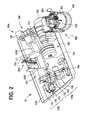
- Fig. 2 is a schematic configuration diagram of the lens processing mechanism section 10 disposed in the housing 2.
- the processing apparatus body 1 includes a lens holding section 100 having lens chuck shafts to hold a lens LE to be processed, and a processing tool rotating unit 160 that rotates a processing tool rotating shaft 161a to which a lens processing tool 168 for processing the peripheral edge of the lens is attached.
- the processing tool rotating unit 160 is disposed in the front of the base 170.
- the lens processing tool 168 is constituted by a roughing grindstone, a bevel-processing and plano-processing finishing grindstone, a flat-polish-finishing grindstone, and the like.
- the processing tool rotating shaft 161a is rotated by a motor 161.
- the lens holding section 100 includes: a lens rotating unit 100a that rotates a pair of lens chuck shafts 102L and 102R; an X-direction moving unit (chuck shaft moving unit) 100b that moves the lens chuck shafts 102L and 102R disposed in a carriage 101 in an axial direction (X direction); and a Y-direction moving unit (inter-shaft distance changing unit) 100c that moves the lens chuck shafts 102L and 102R in such a direction (Y direction) to approach or to be distant from the processing tool rotating shaft 161a.
- a lens rotating unit 100a that rotates a pair of lens chuck shafts 102L and 102R
- an X-direction moving unit (chuck shaft moving unit) 100b that moves the lens chuck shafts 102L and 102R disposed in a carriage 101 in an axial direction (X direction)
- a Y-direction moving unit (inter-shaft distance changing unit) 100c that moves the lens chuck shafts 102L and
- the lens rotating unit 100a has a motor 120 that rotates the pair of lens chuck shafts 102L and 102R held in the carriage 101.
- a motor 110 for moving the lens chuck shaft 102R toward the lens chuck shaft 102L to nip the lens LE between the lens chuck shafts 102L and 102R is disposed in the carriage 101.
- the base portion of a cup CU attached to the front surface of the lens LE is attached to a cup holder (illustration thereof is omitted) disposed on the lens chuck shaft 102L.
- the X-direction moving unit 100b has a motor 145.
- the carriage 101 is mounted on an X-axis movement support base 140 that is able to move along shafts 103 and 104 extending in the X direction.
- the carriage 101 is linearly moved in the X direction along with the support base 140 by the rotation of the motor 145.
- the Y-direction moving unit 100c has a motor 150 mounted on the support base 140.
- the rotation of the motor 150 is transmitted to a ball screw 155 extending in the Y direction, and the carriage 101 is moved in the Y direction by the rotation of the ball screw 155.
- the lens LE held by the lens chuck shafts 102L and 102R is moved in the X direction by the X-direction moving unit 100b such that the position in the X direction thereof with respect to the lens processing tool 168 is changed.
- the distance of the lens LE from the processing tool rotating shaft 161a is changed by the Y-direction moving unit 100c so as to be subjected to peripheral edge processing based on a target lens shape.
- a lens shape measuring unit 200 is disposed in the rear of the carriage 101.
- the lens shape measuring unit 200 has a tracing stylus 260 that comes into contact with the front surface and the rear surface of a lens, and the shapes of the front surface and the rear surface of the lens are measured by detecting the movement position of the tracing stylus 260.
- the lens LE is rotated and the Y-direction moving unit 100c is driven on the basis of a target lens shape, and the position in the X direction of the refractive surface of the lens with which the tracing stylus 260 comes into contact is detected by a sensor (not shown).
- Fig. 3A is a schematic configuration diagram of the blocker unit 500.
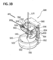
- Fig. 3B is a diagram of a state where a cup attaching portion 560 in Fig. 3A is directed downward.
- Fig. 3C is a diagram of the blocker unit 500 of Fig. 3B viewed in an arrow A01 direction.
- Fig. 4 is a diagram of an optical system disposed in the blocker unit 500.
- the blocker unit 500 includes lens support portions (support pins 505) disposed to support the lens LE on a reference axis L01 extending in the vertical direction, a support arm 562 to which the attaching portion 560 to which the base portion of the cup CU is attached is attached, moving arms 556 that hold the support arm 562 to be rotatable about an axis extending in the lateral direction as the center, and are movable in the upward and downward direction which is the direction of the reference axis L01.
- lens support portions support pins 505
- a support arm 562 to which the attaching portion 560 to which the base portion of the cup CU is attached is attached
- moving arms 556 that hold the support arm 562 to be rotatable about an axis extending in the lateral direction as the center, and are movable in the upward and downward direction which is the direction of the reference axis L01.
- the moving arms 556 hold the support arm 562 to be rotatable about an axis X02 extending in the lateral direction so that the attaching portion 560 is directed in a first direction which is a downward direction, a forward direction in which the operator is positioned with respect to the blocker unit 500, or a second direction which is an upward direction.
- the blocker unit 500 has a lever 564 operated by the operator to rotate the support arm 562 so that the attaching portion 560 is directed in the first direction from the second direction.
- the lever is disposed in the support arm, and preferably, is also used as an operation member for lowering the cup CU attached to the attaching portion 564 along with the moving arms 556 by the operator after the attaching portion 564 is directed in the first direction.
- the blocker unit have a first impelling member (spring 555) that impels the moving arms 556 in the upward direction, a second impelling member (spring 559) that applies an impelling force to rotate the support arm so that the attaching portion is directed in the second direction from the first direction, and a restriction portion 570 that restricts rotation of the support arm so that the center of the attaching portion is positioned on the reference axis L01 when the support arm is rotated to cause the attaching portion to be directed in the first direction.
- the impelling force of the first impelling member is set to be greater than the impelling force of the second impelling member.
- the impelling force of the first impelling member be greater than a moment load in the lever when the support arm is rotated by the impelling force of the second impelling member.
- the second direction in which the attaching portion is directed be in a range of a direction rotated toward the operator side by 45 degrees to 180 degrees with respect to the downward direction of the reference axis L01.
- the lens LE is placed on the support pins 505.
- Two support columns 552 are attached to extend upward from the pedestal 502. The upper ends of the support columns 552 are supported by a block 566.
- Movement support bases 554 to which the moving arms 556 are integrally attached are attached to the support columns 552 to be movable in the upward and downward direction.
- the spring 555 as the impelling member that always impels the movement support base 554 in the upward direction is disposed in the movement support base 554.
- Two arms 556 are disposed to extend forward from the movement support base 554.
- a shaft 558 which is a coaxial with the axis X02 that extends in the lateral direction is mounted to the front portion of the arm 556.
- the support arm 562 that supports the cup attaching portion 560 is held by the arm 556 to rotate about the shaft 558 (the axis X02) so that the cup attaching portion 560 is directed forward (forward an operator) and the cup attaching portion 560 is directed downward.
- the base portion of the cup CU which is a tool for holding the lens LE with the lens chuck shafts 102L and 102R of the lens LE is mounted to a hole provided in the cup attaching portion 560.
- a lever 564 for enabling the operator to rotate the support arm 562 is fixed to the support arm 562.
- the lever 564 has a plate shape.
- the coil spring 559 as the impelling member is disposed in the shaft 558.
- the coil spring 559 applies an impelling force to rotate the support arm 562 so that the attaching portion 560 is directed in the second direction (forward direction) from the downward direction.
- the impelling force of the spring 555 is set to be greater than the impelling force of the coil spring 559.
- a cut-off part 563A formed in the support arm 562 abuts on the restriction portion 570, the rotation of the support arm 562 is restricted in a state where the cup attaching portion 560 is directed in the downward direction.
- a cut-off part 563B is formed in the support arm 562.
- the restriction portion 570 is also used as a restriction portion that restricts rotation of the support arm 562 to cause the cup attaching portion 560 to be directed in the second direction.
- the lever 564 extends substantially in the upward direction as illustrated in Fig. 3A when the attaching portion 560 is directed in the forward direction (second direction), and the lever 564 is disposed to extend substantially in the horizontal direction (in a range of ⁇ 30 degrees with respect to a surface orthogonal to the reference axis L01) when the attaching portion 560 is directed in the downward direction (first direction). Therefore, the operator continuously performs an operation of the lever 564 when the attaching portion 560 is directed in the downward direction from the forward direction and an operation of the lever 564 when the attaching portion 560 is lowered toward the lens LE placed on the support pins 505 in association with each other.
- the second direction in which the attaching portion 560 is directed is a direction in which the operator substantially faces the front in the example of Fig. 3A .
- the second direction in which the attaching portion 560 is directed may be a range of a direction rotated by 45 degrees to 180 degrees with respect to the downward direction of the reference axis L01. In this range, the base portion of the cup CU may be attached to the attaching portion 560 while the operator views the hole of the attaching portion 560.
- the attaching portion 560 is in a state of being directed in the forward direction (second direction) by the coil spring 559.
- the operator mounts the base portion of the cup CP to the attaching portion 560 in this state.
- the operator is able to check the hole of the attaching portion 560, and thus it is easy to mount the base portion of the cup CU to the attaching portion 560.
- the operator operates the lever 564 and rotates the lever 564 directed in the upward direction toward the forward direction.
- an impelling force is applied by the coil spring 559 in the direction in which the operator rotates the lever 564.
- the rotation of the support arm 562 (the attaching portion 560) is restricted by the restriction portion 570.
- a state in which the attaching portion 560 is directed in the downward direction is achieved, and the lever 564 is substantially in the horizontal direction, and a force of the operator for operating the lever 564 is in the downward direction.
- an impelling force in the upward direction is applied to the moving arms 556 to which the support arm 562 is attached by the spring 555.
- the impelling force of the spring 555 is set to be greater than the impelling force of the coil spring 559, the moving arms 556 are not lowered until the rotation of the support arm 562 is restricted by the restriction portion 570.
- the rotation of the support arm 562 is restricted by the restriction portion 570, when the operator continuously presses the lever 564, the pressing force is directed in the downward direction, and thus the attaching portion 560 and the cup CU are lowered along with the moving arms 556. Accordingly, the cup CU is fixed to the front surface of the lens LE. After fixing of the cup CU to the lens LE is completed, when the operator raises the finger in the upward direction and removes the finger from the lever 564, the support arm 562 is raised along with the moving arms 556 by the spring 555, and the rotation of the support arm 562 is returned to its original state by the coil spring 559. Accordingly, the position and the direction of the attaching portion 560 are returned to the initial states.
- the operator need to perform a first operation of rotating an arm having a attaching portion into which a cup is inserted in the horizontal direction about an axis in the upward and downward direction as the center, and a second operation of lowering the arm.
- the direction of the first operation and the direction of the second operation are different, have no association in the operation directions, and have no continuity.
- the blocker unit 500 described in the specification after performing the operation of bringing down the lever 564 directed in the upward direction to be lowered, the operator performs the operation of continuously pressing the lever 564 in the downward direction, thereby fixing the cup to the lens.
- Fig. 4 is a diagram of the optical system disposed in the blocker unit 500.
- the blocker unit 500 includes an illumination optical system 520 that illuminates the lens LE, and an imaging optical system 530 that takes an image of the lens LE.
- the illumination optical system 520 includes: a light source 521 such as an LED that emits white light; a mirror 523 that changes the direction of the illumination light; and a retroreflective member 527 disposed at the lower side of the transparent plate 503.
- the retroreflective member 527 is a member that has a characteristic of reflecting incident light in its original incident direction.
- the lens LE placed on the support pins 505 is illuminated from the below by the retroreflective member 527.
- the imaging optical system 530 uses the mirror 523 of the illumination optical system 520 in common, and a half mirror 531 is disposed between the mirror 523 and the light source 521. In the reflected direction of the half mirror 531, an aperture 532, a lens 533, and an imaging element (camera) 534 are disposed.
- the aperture 532 is disposed at a position that is substantially a conjugate of the light source 521 via the half mirror 531.
- the optical axis of the imaging optical system 530 (the lens 533) is disposed to be aligned with the reference shaft L01.
- the focal position of the imaging optical system 530 is set to substantially focus on the surface of the lens LE placed on the support pins 505.
- the image of the front surface side of the lens LE is imaged by the imaging element 534 of the imaging optical system 530.
- the image of the lens LE taken by the imaging element 534 is displayed on the display unit 40.
- Fig. 5 is a control block diagram associated with the eyeglass lens processing apparatus.
- a memory 51, the lens processing mechanism section 10, the eyeglass frame shape measuring unit 30, the display unit 40, and the blocker unit 500 are connected to a control section 50.
- the control section 50 receives an input signal through the touch panel function included in the display unit 40 and controls a display of figures and information on the screen.
- the display unit 40 is used in common in the stage of measuring the shape of a rim by the eyeglass frame shape measuring unit 30, the stage of attaching the cup by the blocker unit 500, and the stage of processing the lens LE by the lens processing mechanism section 10.
- the operator through the display unit 40 as the center, the operator has the display unit 40 as the center in the arrangement of the window 12, the eyeglass frame shape measuring unit 30, and the blocker unit 500 as described above, and thus the movement of the line of sight of a worker and the distance of the flow line of a work are shortened. Therefore, the operator may efficiency perform the work in each stage.
- Figs. 6 to 12 are examples of screens switched and displayed on the display unit 40.
- a switch 404a is a switch that inputs a signal for switching to a screen of the next operation order.
- the control section 50 sequentially switches predetermined screens according to each of the operations processes including rim shape measurement, cup attaching, and lens processing on the basis of the input signal for screen switching by the switch 404a and displays the screens on the display unit 40.
- the operator performs measurement of the shape of the rim of an eyeglass frame using the eyeglass frame shape measuring unit 30.
- a trace mode is selected from a menu screen (illustration thereof is omitted) displayed on the display unit 40, as illustrated in Fig. 6 , a screen 410 for starting the measurement by the eyeglass frame shape measuring unit 30 is displayed on the display unit 40.
- a switch 411a for starting measurement of the right rim of the eyeglass frame a switch 411b for starting measurement of the left rim, and a switch 411c for sequentially starting the measurements of the right rim and the left rim are displayed.
- the switch 404a is a switch that inputs a signal for switching to a screen of the next process.
- a switch 404b is a switch that inputs a signal for returning to the previous screen.
- a switch 402a is a switch that sends a command to nip the lens LE with the pair of lens chuck shafts 102L and 102R included in the lens processing mechanism section 10.
- a switch 402d is a switch that inputs a signal for stopping lens processing on the way. The switches 402a and 402d may not be displayed on the screens in stages in which processing of the lens LE is not performed.
- the measurement result (target lens shape) is stored (input) in the memory 51.
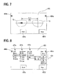
- the screen of the display 40 is switched to a screen 415 illustrated in Fig. 7 .
- target lens shape figures TS are displayed as the target lens shapes of the left rim and the right rim.
- a value indicating a frame papillary distance FPD between the left and right rims is displayed through the measurements of the left and right rims.
- the screen of the display 40 is switched to a screen 420 for inputting processing conditions for the lens LE as illustrated in Fig. 8 .
- the operator may recognize that inputting of processing conditions is needed in this stage.
- the material of the eyeglass frame may be selected by a switch of a display portion 422s
- the material of the lens LE may be selected by a switch of a display portion 422n
- the kind of the lens LE may be selected by a switch of a display portion 422c.
- processing modes (bevel-processing, plano-processing, and the like) and chamfering may be selected by switches of a display portion 424.
- switches of a display portion 424 a switch that selects the center of attaching of the cup with respect to the lens LE from the optical center of the lens and the center of the target lens shape is disposed.
- the screen of the display unit 40 is changed to a screen 425 to which data for a layout of the positional relationship of the lens with respect to the target lens shape is input.
- the screen is switched to the input screen 425 for a layout of the optical center OC of the lens LE with respect to the geometric center FC of the target lens shape.
- layout data including the papillary distance PD of a wearer, the height of the optical center OC with respect to the geometric center FC, and the like may be input.
- the input layout data is stored in the memory 51.
- the input screen 425 for the layout may be a screen that also functions as the input screen 420 for the processing conditions of Fig. 8 .
- the screen of the display 40 is switched to a screen 430 illustrating a transition to the cup attaching process by the blocker unit 500 as illustrated in Fig. 10 . Accordingly, the operator may recognize that the cup attaching work is needed.
- the screen 430 is a display example in a case where the lens LE for the right eye is selected by a switch 402b.
- the cup attaching operation using the blocker unit 500 will be simply described.
- the operator places an unprocessed lens LE on the support pins 505 of the blocker unit 500.
- the lens LE is illuminated by the illumination optical system 520, and the image of the lens LE is taken by the imaging element 534.
- a lens image LEM taken by the imaging element 534 is displayed on a display portion 432 of the screen 430.
- the lens image LEM also includes an image 434b of a printed dot mark that is attached in advance.
- a target lens shape figure TS for the right eye obtained by the eyeglass frame shape measuring unit 30 is displayed by being synthesized (superimposed) with the lens image LEM.
- the display position of the target lens shape figure TS on the display portion 432 is determined on the basis of the layout data and selection of the position of the cup attaching center, and the display of the target lens shape figure TS is controlled by the control section 50.
- the display portion 432 displays a guide mark 435 for aligning the position of the printed dot mark image 434b, which is synthesized (superimposed) with the lens image LEM. As the operator moves the lens LE to enable the guide mark 435 and the printed dot mark image 434b have a predetermined positional relationship, the position of the reference axis L01 may be aligned with the cup attaching center of the lens LE.
- a display portion 431 displays setting data for the layout data and the processing conditions (detailed illustration is omitted).
- the operator rotates the lever 564 in the downward direction and further lowers the lever 564. Accordingly, the cup CU is attached to the surface of the lens.
- the cup CU is attached to the lens LE for the left eye in the same order.
- a screen 435 illustrating a transition to a stage in which lens processing is able to be performed by the lens processing mechanism 10 is displayed.
- a switch 402c that inputs a signal for allowing the lens processing mechanism section 10 to start processing of the lens LE is displayed.
- the switch 402b that inputs a signal for selecting any of the left and the right of the lens LE to be processed is displayed. Accordingly, the operator may recognize that the stage proceeds to the stage of performing the processing of the lens LE as the next stage.
- a display for checking the layout data is made at the center of a screen 435.
- the operator opens the window 12 disposed above the lens processing mechanism section 10 and holds the lens LE with the lens chuck shafts 102L and 102R.
- the motor 110 is driven by the control of the control section 50 to move the lens chuck shaft 102R.
- the control section 50 executes lens shape measurement using the lens shape measuring unit 200.
- the screen 440 is an example of a simulation screen during bevel-processing.
- the target lens shape figure TS, and a figure 442 of a bevel cross-section at the edge position designated by a cursor 444 are displayed.
- the position of the cursor 444 may be changed by switches 445a and 445b.
- the bevel position for the lens edge during bevel-processing may be adjusted by changing the value of condition data of a display field 446.
- the operator may confirm whether or not it is appropriate to perform bevel-processing, and conditions of bevel-processing may be changed.
- the switch 402c is pushed again, driving of the X-direction moving unit 100b and the Y-direction moving unit 100c is controlled, and processing of the peripheral edge of the lens LE is performed by the lens processing tool 168.
- screens in a predetermined order according to the operation processes including rim shape measurement, cup attaching, and lens processing are sequentially switched and displayed on the basis of the input signals while the screens are switched, an operator who is unaccustomed to processing may also smoothly work.
- the switched displays of the screens inputting of data needed for processing is accurately performed. Accordingly, the operator efficiently performs a series of the works including rim shape measurement, cup attaching, and lens processing.
Landscapes
- Engineering & Computer Science (AREA)
- Mechanical Engineering (AREA)
- Chemical & Material Sciences (AREA)
- Ceramic Engineering (AREA)
- Inorganic Chemistry (AREA)
- Health & Medical Sciences (AREA)
- Manufacturing & Machinery (AREA)
- Ophthalmology & Optometry (AREA)
- Grinding And Polishing Of Tertiary Curved Surfaces And Surfaces With Complex Shapes (AREA)
- Eyeglasses (AREA)
- Beverage Vending Machines With Cups, And Gas Or Electricity Vending Machines (AREA)
Abstract
Description
- The present invention relates to an apparatus having a cup attaching unit for attaching cup which is a processing tool to a surface of an eyeglass lens.
- When the peripheral edge of an eyeglass lens is processed, a process of obtaining a target lens shape by measuring the shape of the rim of an eyeglass frame using an eyeglass frame shape measuring device, a process of attaching a cup which is a processing tool to the front surface of the lens using a cup attaching device (blocker), a process of inputting processing conditions of the lens, and a process of holding the lens to which the cup is attached with lens chuck shafts included in an eyeglass lens processing apparatus body to perform processing of the peripheral edge of the lens on the basis of the target lens shape and the processing conditions are performed. The eyeglass frame shape measuring device and the cup attaching device are separated from the processing apparatus body. However, a system in which the eyeglass frame shape measuring device is assembled into the processing apparatus body (for example, refer to
JP-A-2000-314617 JP-A-2007-275998 JP-A-2008-246634 - However, in the apparatus according to the related art, a system for performing each of the processes including the process of attaching the cup to the front surface of the lens after obtaining the target lens shape, the process of performing processing of the lens by the eyeglass lens processing apparatus body, and the like is not integral, and thus an operator needs to perform each work while recognizing each of the processes. When the devices are independent from each other, an unskilled operator may get bewildered by correlations therebetween and the work order, resulting in a reduction in work efficiency. In addition, when the devices are independent from each other, an installation space needs to be ensured.
In addition, in the manual type cup attaching device according to the related art as in Patent Document 3, the attaching portion to which the base portion of the cap is attached is fixed while facing downward, and thus the operator is difficult to mount the cup to the attaching portion. - A technical object of the invention is to provide an apparatus capable of achieving an improvement in the apparatus according to the related art. In addition, another technical object of the invention is to provide an apparatus capable of improving operability. In addition, another technical object of the invention is to provide an apparatus capable of enabling works to be smoothly performed. In addition, another technical object of the invention is to provide an apparatus capable of achieving an increase in the efficiency of works. In addition, another technical object of the invention is to provide an apparatus which is advantageous in terms of an installation space and cost of the apparatus.
- In order to accomplish the objects, the invention has the following configurations.
- (1) An apparatus including a cup attaching unit for attaching a cup, which is a processing jig, to a surface of an eyeglass lens, the apparatus comprising:
- a lens support portion for supporting a lens on a reference axis extending in a vertical direction;
- a support arm to which an attaching portion to which a base portion of the cup is attached is attached;
- a moving arm for support the support arm to be movable around an axis extending a lateral direction so that the attaching portion can be directed in a first direction which is a downward direction toward the lens support portion and in a second direction which is an upward direction or a forward direction in which an operation is positioned with respect to the apparatus; and
- a lever configured to be operated by the operation and rotate the support arm so as to direct the attaching portion in from the second direction to the first direction,
- wherein the lever is provided at the support arm and lowers the attaching portion together with the moving arm after the attaching portion is directed in the first direction.
- (2) The apparatus according to (1), wherein the cup attaching portion includes:
- a first urging member for urging the moving arm upwardly;
- second urging member for applying urging force to rotate the support arm so that the attaching portion is directed in from the first direction to the second direction; and
- a restricting member for restricting the rotation of the support arm so that a center of the attaching portion is positioned above the reference axis when the support arm is rotated so as to direct the attaching portion in the first direction.
- (3) The apparatus according to (2), wherein urging force of the first urging member is larger than that of the second urging member.
- (4) The apparatus according to (1), wherein the second direction is a direction in a range of a direction rotated toward the operator side by 45 degrees to 180 degrees with respect to the downward direction of the reference axis.
- (5) The apparatus according to (1), wherein the lever is arranged so as to extend in a substantially horizontal direction when the attaching portion is directed in the first direction.
- (6) The apparatus according to (1) further comprising:
- a processing apparatus body having a housing where a lens processing mechanism having a processing tool for processing a periphery of the eyeglass lens held by a lens chuck shaft is arranged,
- a display unit arranged in the housing;
- a signal input unit for inputting a switching signal for switching a screen of the display unit to a next process step screen;
- a control unit for controlling the display unit, based on the switching signal, to display, in a predetermined order, a screen to which data for a layout of a positional relationship of the lens with respect to a target lens shape is input, a screen illustrating a transition to a cup attaching process by the cup attaching unit, and a screen illustrating a transition to a stage in which lens processing is able to be performed by the lens processing mechanism.
- (7) The apparatus according to (6), wherein
the processing apparatus body includes a base to which the lens processing mechanism is mounted, and
the cup attaching unit is mounted on the base, and is integrally arranged with the processing apparatus body. - (8) The apparatus according to (6), wherein
the cup attaching unit includes a camera for imaging the lens,
the control unit controls the display unit to display a lens image imaged by the camera and superimposes a figure of the target lens shape on the lens image. - (9) An apparatus including a cup attaching unit for attaching a cup, which is a processing jig, to a surface of an eyeglass lens, the apparatus comprising:
- a processing apparatus body having a housing where a lens processing mechanism having a processing tool for processing a periphery of the eyeglass lens held by a lens chuck shaft is arranged,
- a display unit arranged in the housing;
- a signal input unit for inputting a switching signal for switching a screen of the display unit to a next process step screen;
- a control unit for controlling the display unit, based on the switching signal, to display, in a predetermined order, a screen to which data for a layout of a positional relationship of the lens with respect to a target lens shape is input, a screen illustrating a transition to a cup attaching process by the cup attaching unit, and a screen illustrating a transition to a stage in which lens processing is able to be performed by the lens processing mechanism.
- (10) The apparatus according to (9), wherein
the processing apparatus body includes a base to which the lens processing mechanism is mounted, and
the cup attaching unit is mounted on the base, and is integrally arranged with the processing apparatus body. - (11) The apparatus according to (9), wherein
the cup attaching unit includes a camera for imaging the lens,
the control unit controls the display unit to display a lens image imaged by the camera and superimposes a figure of the target lens shape on the lens image. - (12) The apparatus according to (9) further comprising:
- an eyeglass frame shape measuring unit for obtaining the target lens shape by measuring a shape of a rim of an eyeglass frame, and
- a window configured to be opened and closed, the window being provided at an upper surface of the housing to take the eyeglass lens in and out of the lens processing mechanism,
- wherein the eyeglass frame shape measuring unit is arranged behind the display unit, the cup attaching unit is arranged in front of the display unit, and the window is arranged at a side of the display unit.
- According to the invention, the improvement in the apparatus according to the related art may be achieved. In addition, the improvement in operability may be achieved. In addition, works may be smoothly performed even by an unskilled operator. In addition, an increase in efficiency of works may be achieved. In addition, an apparatus which is advantageous in terms of an installation space and cost of the apparatus may be provided.
-
-
Fig. 1 is a perspective view of the external form of an eyeglass lens processing apparatus. -
Fig. 2 is a schematic configuration diagram of a lens processing mechanism section. -
Fig. 3A is a schematic configuration diagram of a blocker unit. -
Fig. 3B is a schematic configuration diagram of the blocker unit. -
Fig. 3C is a diagram of the blocker unit ofFig. 3B viewed in an arrow A01 direction. -
Fig. 4 is a diagram of an optical system disposed in the blocker unit. -
Fig. 5 is a control block diagram associated with the eyeglass lens processing apparatus. -
Fig. 6 is an example of a screen switched and displayed on a display unit. -
Fig. 7 is an example of a screen switched and displayed on a display unit. -
Fig. 8 is an example of a screen switched and displayed on a display unit. -
Fig. 9 is an example of a screen switched and displayed on a display unit. -
Fig. 10 is an example of a screen switched and displayed on a display unit. -
Fig. 11 is an example of a screen switched and displayed on a display unit. -
Fig. 12 is an example of a screen switched and displayed on a display unit. - Hereinafter, an embodiment of the invention will be described with reference to the drawings.
Fig. 1 is a perspective view of an external form as a schematic configuration diagram of an eyeglass lens processing apparatus. - A
processing apparatus body 1 includes: a base 170; a lens processing mechanism section 10 (seeFig. 2 ) disposed in ahousing 2 of theprocessing apparatus body 1; a window (door) 12 which is able to be opened and closed to take an eyeglass lens in and out of the lensprocessing mechanism section 10, thewindow 12 being disposed in the vicinity of the center in the left and right direction on the surface of thehousing 2; an eyeglass frameshape measuring unit 30 which is disposed at the rear right side of thehousing 2 with respect to thewindow 12; adisplay unit 40 which is disposed on the surface of thehousing 2 in front of the eyeglass frameshape measuring unit 30 on the right of thewindow 12; and a blocker unit (cup attaching unit) 500 which is disposed in front of thedisplay unit 40 at the front right side of thehousing 2 in order to mount a cup which is a processing tool to the surface of the eyeglass lens. The lensprocessing mechanism section 10, the eyeglass frameshape measuring unit 30, thedisplay unit 40, and theblocker unit 500 are mounted to the base 170 in one body.
Thedisplay unit 40 is disposed at the rear right side of thehousing 2 with respect to thewindow 12. The eyeglass frameshape measuring unit 30 is disposed in the rear of thehousing 2 with respect to thedisplay unit 40. Theblocker unit 500 is disposed in the front of thehousing 2 with respect to thedisplay unit 40. In this embodiment, as viewed from an operator, thedisplay unit 40 is disposed at the right side of thewindow 12, the eyeglass frameshape measuring unit 30 is disposed at the rear right side, and theblocker unit 500 is disposed at the front right side. Thedisplay unit 40, the eyeglass frameshape measuring unit 30, and theblocker unit 500 may also be disposed on the left of thewindow 12. - The eyeglass frame
shape measuring unit 30 has a frame holding mechanism that holds an eyeglass frame, and a measuring mechanism which measures the three-dimensional shape of a rim by detecting the movement of a tracing stylus inserted into the groove of the rim of the eyeglass frame. The eyeglass frameshape measuring unit 30 may use a unit that has a well-known configuration. - The
display unit 40 has a display with a touch panel function. As the operator touches a switch displayed on the screen of thedisplay unit 40, a signal corresponding to a display of the switch is input. In addition, thedisplay unit 40 is used in common in a stage of measuring the shape of a rim by the eyeglass frameshape measuring unit 30, a stage of attaching a cup by theblocker unit 500, and a stage of processing a lens LE by the lensprocessing mechanism section 10. -
Fig. 2 is a schematic configuration diagram of the lensprocessing mechanism section 10 disposed in thehousing 2. Theprocessing apparatus body 1 includes alens holding section 100 having lens chuck shafts to hold a lens LE to be processed, and a processingtool rotating unit 160 that rotates a processing tool rotating shaft 161a to which alens processing tool 168 for processing the peripheral edge of the lens is attached. - The processing
tool rotating unit 160 is disposed in the front of thebase 170. Thelens processing tool 168 is constituted by a roughing grindstone, a bevel-processing and plano-processing finishing grindstone, a flat-polish-finishing grindstone, and the like. The processing tool rotating shaft 161a is rotated by amotor 161. - The
lens holding section 100 includes: alens rotating unit 100a that rotates a pair oflens chuck shafts lens chuck shafts carriage 101 in an axial direction (X direction); and a Y-direction moving unit (inter-shaft distance changing unit) 100c that moves thelens chuck shafts - The
lens rotating unit 100a has amotor 120 that rotates the pair oflens chuck shafts carriage 101. In addition, amotor 110 for moving thelens chuck shaft 102R toward thelens chuck shaft 102L to nip the lens LE between thelens chuck shafts carriage 101. The base portion of a cup CU attached to the front surface of the lens LE is attached to a cup holder (illustration thereof is omitted) disposed on thelens chuck shaft 102L. - The
X-direction moving unit 100b has amotor 145. Thecarriage 101 is mounted on an X-axismovement support base 140 that is able to move alongshafts carriage 101 is linearly moved in the X direction along with thesupport base 140 by the rotation of themotor 145. - The Y-
direction moving unit 100c has amotor 150 mounted on thesupport base 140. The rotation of themotor 150 is transmitted to aball screw 155 extending in the Y direction, and thecarriage 101 is moved in the Y direction by the rotation of theball screw 155. - The lens LE held by the
lens chuck shafts X-direction moving unit 100b such that the position in the X direction thereof with respect to thelens processing tool 168 is changed. In addition, the distance of the lens LE from the processing tool rotating shaft 161a is changed by the Y-direction moving unit 100c so as to be subjected to peripheral edge processing based on a target lens shape. - In the rear of the
carriage 101, a lensshape measuring unit 200 is disposed. The lensshape measuring unit 200 has atracing stylus 260 that comes into contact with the front surface and the rear surface of a lens, and the shapes of the front surface and the rear surface of the lens are measured by detecting the movement position of thetracing stylus 260. During lens shape measurement, the lens LE is rotated and the Y-direction moving unit 100c is driven on the basis of a target lens shape, and the position in the X direction of the refractive surface of the lens with which thetracing stylus 260 comes into contact is detected by a sensor (not shown). -
Fig. 3A is a schematic configuration diagram of theblocker unit 500.Fig. 3B is a diagram of a state where acup attaching portion 560 inFig. 3A is directed downward.Fig. 3C is a diagram of theblocker unit 500 ofFig. 3B viewed in an arrow A01 direction.Fig. 4 is a diagram of an optical system disposed in theblocker unit 500. Theblocker unit 500 includes lens support portions (support pins 505) disposed to support the lens LE on a reference axis L01 extending in the vertical direction, asupport arm 562 to which the attachingportion 560 to which the base portion of the cup CU is attached is attached, movingarms 556 that hold thesupport arm 562 to be rotatable about an axis extending in the lateral direction as the center, and are movable in the upward and downward direction which is the direction of the reference axis L01. The movingarms 556 hold thesupport arm 562 to be rotatable about an axis X02 extending in the lateral direction so that the attachingportion 560 is directed in a first direction which is a downward direction, a forward direction in which the operator is positioned with respect to theblocker unit 500, or a second direction which is an upward direction.
In addition, theblocker unit 500 has alever 564 operated by the operator to rotate thesupport arm 562 so that the attachingportion 560 is directed in the first direction from the second direction. The lever is disposed in the support arm, and preferably, is also used as an operation member for lowering the cup CU attached to the attachingportion 564 along with the movingarms 556 by the operator after the attachingportion 564 is directed in the first direction.
In addition, it is preferable that the blocker unit have a first impelling member (spring 555) that impels the movingarms 556 in the upward direction, a second impelling member (spring 559) that applies an impelling force to rotate the support arm so that the attaching portion is directed in the second direction from the first direction, and arestriction portion 570 that restricts rotation of the support arm so that the center of the attaching portion is positioned on the reference axis L01 when the support arm is rotated to cause the attaching portion to be directed in the first direction.
In addition, the impelling force of the first impelling member is set to be greater than the impelling force of the second impelling member. Moreover, it is preferable that the impelling force of the first impelling member be greater than a moment load in the lever when the support arm is rotated by the impelling force of the second impelling member. In addition, it is preferable that the second direction in which the attaching portion is directed be in a range of a direction rotated toward the operator side by 45 degrees to 180 degrees with respect to the downward direction of the reference axis L01.
A specific example of a cup attaching mechanism of theblocker unit 500 is as follows. InFigs. 3A and3B , atransparent plate 503 is disposed on apedestal 502. On thetransparent plate 503, three support pins (lens support portions) 505 are provided about a reference axis L01 for cup attaching as the center. The lens LE is placed on the support pins 505. Twosupport columns 552 are attached to extend upward from thepedestal 502. The upper ends of thesupport columns 552 are supported by ablock 566. Movement support bases 554 to which the movingarms 556 are integrally attached are attached to thesupport columns 552 to be movable in the upward and downward direction. Thespring 555 as the impelling member that always impels themovement support base 554 in the upward direction is disposed in themovement support base 554. Twoarms 556 are disposed to extend forward from themovement support base 554. Ashaft 558 which is a coaxial with the axis X02 that extends in the lateral direction is mounted to the front portion of thearm 556. - The
support arm 562 that supports thecup attaching portion 560 is held by thearm 556 to rotate about the shaft 558 (the axis X02) so that thecup attaching portion 560 is directed forward (forward an operator) and thecup attaching portion 560 is directed downward. The base portion of the cup CU which is a tool for holding the lens LE with thelens chuck shafts cup attaching portion 560. In addition, alever 564 for enabling the operator to rotate thesupport arm 562 is fixed to thesupport arm 562. Thelever 564 has a plate shape.
Thecoil spring 559 as the impelling member is disposed in theshaft 558. When the operator does not operate thelever 564, thecoil spring 559 applies an impelling force to rotate thesupport arm 562 so that the attachingportion 560 is directed in the second direction (forward direction) from the downward direction. In addition, the impelling force of thespring 555 is set to be greater than the impelling force of thecoil spring 559.
When thelever 564 is operated by a finger of the operator and thesupport arm 562 is rotated so that the center of thecup attaching portion 560 is positioned on the reference axis L01 as illustrated inFigs. 3B and3C , therestriction portion 570 for restricting the rotation of thesupport arm 562 is provided in the movingarms 556. InFig. 3C , as a cut-offpart 563A formed in thesupport arm 562 abuts on therestriction portion 570, the rotation of thesupport arm 562 is restricted in a state where thecup attaching portion 560 is directed in the downward direction.
In addition, separately from the cut-offpart 563A, a cut-offpart 563B is formed in thesupport arm 562. When thecup attaching portion 560 is rotated to be directed in the forward direction by thecoil spring 559, the cut-offpart 563B abuts on therestriction portion 570 such that the rotation of thesupport arm 562 is restricted. Therestriction portion 570 is also used as a restriction portion that restricts rotation of thesupport arm 562 to cause thecup attaching portion 560 to be directed in the second direction.
In addition, thelever 564 extends substantially in the upward direction as illustrated inFig. 3A when the attachingportion 560 is directed in the forward direction (second direction), and thelever 564 is disposed to extend substantially in the horizontal direction (in a range of ±30 degrees with respect to a surface orthogonal to the reference axis L01) when the attachingportion 560 is directed in the downward direction (first direction). Therefore, the operator continuously performs an operation of thelever 564 when the attachingportion 560 is directed in the downward direction from the forward direction and an operation of thelever 564 when the attachingportion 560 is lowered toward the lens LE placed on the support pins 505 in association with each other.
In addition, the second direction in which the attachingportion 560 is directed is a direction in which the operator substantially faces the front in the example ofFig. 3A . However, the second direction in which the attachingportion 560 is directed may be a range of a direction rotated by 45 degrees to 180 degrees with respect to the downward direction of the reference axis L01. In this range, the base portion of the cup CU may be attached to the attachingportion 560 while the operator views the hole of the attachingportion 560. - A cup attaching operation by the cup attaching mechanism as described above will be described. When the operator does not operate the lever, as illustrated in
Fig. 3A , the attachingportion 560 is in a state of being directed in the forward direction (second direction) by thecoil spring 559. The operator mounts the base portion of the cup CP to the attachingportion 560 in this state. Here, the operator is able to check the hole of the attachingportion 560, and thus it is easy to mount the base portion of the cup CU to the attachingportion 560.
The operator operates thelever 564 and rotates thelever 564 directed in the upward direction toward the forward direction. Here, an impelling force is applied by thecoil spring 559 in the direction in which the operator rotates thelever 564. When the operator rotates thelever 564 against the impelling force, the rotation of the support arm 562 (the attaching portion 560) is restricted by therestriction portion 570. Here, a state in which the attachingportion 560 is directed in the downward direction is achieved, and thelever 564 is substantially in the horizontal direction, and a force of the operator for operating thelever 564 is in the downward direction. In addition, an impelling force in the upward direction is applied to the movingarms 556 to which thesupport arm 562 is attached by thespring 555. However, since the impelling force of thespring 555 is set to be greater than the impelling force of thecoil spring 559, the movingarms 556 are not lowered until the rotation of thesupport arm 562 is restricted by therestriction portion 570. After the rotation of thesupport arm 562 is restricted by therestriction portion 570, when the operator continuously presses thelever 564, the pressing force is directed in the downward direction, and thus the attachingportion 560 and the cup CU are lowered along with the movingarms 556. Accordingly, the cup CU is fixed to the front surface of the lens LE.
After fixing of the cup CU to the lens LE is completed, when the operator raises the finger in the upward direction and removes the finger from thelever 564, thesupport arm 562 is raised along with the movingarms 556 by thespring 555, and the rotation of thesupport arm 562 is returned to its original state by thecoil spring 559. Accordingly, the position and the direction of the attachingportion 560 are returned to the initial states.
In the apparatus ofJP-A-2008-246634 blocker unit 500 described in the specification, after performing the operation of bringing down thelever 564 directed in the upward direction to be lowered, the operator performs the operation of continuously pressing thelever 564 in the downward direction, thereby fixing the cup to the lens. -
Fig. 4 is a diagram of the optical system disposed in theblocker unit 500. Theblocker unit 500 includes an illuminationoptical system 520 that illuminates the lens LE, and an imagingoptical system 530 that takes an image of the lens LE. The illuminationoptical system 520 includes: alight source 521 such as an LED that emits white light; amirror 523 that changes the direction of the illumination light; and aretroreflective member 527 disposed at the lower side of thetransparent plate 503. Theretroreflective member 527 is a member that has a characteristic of reflecting incident light in its original incident direction. The lens LE placed on the support pins 505 is illuminated from the below by theretroreflective member 527. - The imaging
optical system 530 uses themirror 523 of the illuminationoptical system 520 in common, and ahalf mirror 531 is disposed between themirror 523 and thelight source 521. In the reflected direction of thehalf mirror 531, anaperture 532, alens 533, and an imaging element (camera) 534 are disposed. Theaperture 532 is disposed at a position that is substantially a conjugate of thelight source 521 via thehalf mirror 531. The optical axis of the imaging optical system 530 (the lens 533) is disposed to be aligned with the reference shaft L01. In addition, the focal position of the imagingoptical system 530 is set to substantially focus on the surface of the lens LE placed on the support pins 505. The image of the front surface side of the lens LE is imaged by theimaging element 534 of the imagingoptical system 530. The image of the lens LE taken by theimaging element 534 is displayed on thedisplay unit 40. -
Fig. 5 is a control block diagram associated with the eyeglass lens processing apparatus. A memory 51, the lensprocessing mechanism section 10, the eyeglass frameshape measuring unit 30, thedisplay unit 40, and theblocker unit 500 are connected to acontrol section 50. Thecontrol section 50 receives an input signal through the touch panel function included in thedisplay unit 40 and controls a display of figures and information on the screen. - In addition, the
display unit 40 is used in common in the stage of measuring the shape of a rim by the eyeglass frameshape measuring unit 30, the stage of attaching the cup by theblocker unit 500, and the stage of processing the lens LE by the lensprocessing mechanism section 10. In addition, through thedisplay unit 40 as the center, the operator has thedisplay unit 40 as the center in the arrangement of thewindow 12, the eyeglass frameshape measuring unit 30, and theblocker unit 500 as described above, and thus the movement of the line of sight of a worker and the distance of the flow line of a work are shortened. Therefore, the operator may efficiency perform the work in each stage. - Next, the operations of the apparatus will be described.
Figs. 6 to 12 are examples of screens switched and displayed on thedisplay unit 40. In each of the diagrams, aswitch 404a is a switch that inputs a signal for switching to a screen of the next operation order. Thecontrol section 50 sequentially switches predetermined screens according to each of the operations processes including rim shape measurement, cup attaching, and lens processing on the basis of the input signal for screen switching by theswitch 404a and displays the screens on thedisplay unit 40. - As the initial work process, first, the operator performs measurement of the shape of the rim of an eyeglass frame using the eyeglass frame
shape measuring unit 30. When a trace mode is selected from a menu screen (illustration thereof is omitted) displayed on thedisplay unit 40, as illustrated inFig. 6 , ascreen 410 for starting the measurement by the eyeglass frameshape measuring unit 30 is displayed on thedisplay unit 40. On thescreen 410, aswitch 411a for starting measurement of the right rim of the eyeglass frame, aswitch 411b for starting measurement of the left rim, and aswitch 411c for sequentially starting the measurements of the right rim and the left rim are displayed. - In
Fig. 6 , theswitch 404a is a switch that inputs a signal for switching to a screen of the next process. Aswitch 404b is a switch that inputs a signal for returning to the previous screen. In addition, aswitch 402a is a switch that sends a command to nip the lens LE with the pair oflens chuck shafts processing mechanism section 10. Aswitch 402d is a switch that inputs a signal for stopping lens processing on the way. Theswitches - When the
switch 411c ofFig. 6 is selected and measurements of the right rim and the left rim are performed by the eyeglass frameshape measuring unit 30, the measurement result (target lens shape) is stored (input) in the memory 51. After measurements of the shapes of the rims, when theswitch 404a is pushed, the screen of thedisplay 40 is switched to ascreen 415 illustrated inFig. 7 . In thescreen 415, target lens shape figures TS are displayed as the target lens shapes of the left rim and the right rim. In addition, a value indicating a frame papillary distance FPD between the left and right rims is displayed through the measurements of the left and right rims. As thescreen 415 is displayed, the operator is able to see that the left and right target lens shapes are obtained by the eyeglass frameshape measuring unit 30 and is able to confirm the shapes of the target lens shapes. - Next, when the
switch 404a is pushed, the screen of thedisplay 40 is switched to ascreen 420 for inputting processing conditions for the lens LE as illustrated inFig. 8 . By displaying thescreen 420, the operator may recognize that inputting of processing conditions is needed in this stage. On thescreen 420, the material of the eyeglass frame may be selected by a switch of a display portion 422s, the material of the lens LE may be selected by a switch of a display portion 422n, and the kind of the lens LE (single vision lens, bifocal lens, progressive lens, and the like) may be selected by a switch of adisplay portion 422c. In addition, processing modes (bevel-processing, plano-processing, and the like) and chamfering may be selected by switches of adisplay portion 424. In addition, in thedisplay portion 424, a switch that selects the center of attaching of the cup with respect to the lens LE from the optical center of the lens and the center of the target lens shape is disposed. - When the
switch 404a on thescreen 420 ofFig. 8 is pushed, as illustrated inFig. 9 , the screen of thedisplay unit 40 is changed to ascreen 425 to which data for a layout of the positional relationship of the lens with respect to the target lens shape is input. For example, the screen is switched to theinput screen 425 for a layout of the optical center OC of the lens LE with respect to the geometric center FC of the target lens shape. By displaying thescreen 425, the operator may recognize that inputting of layout data is needed in this stage. By touching display fields of numerical values of thescreen 425, layout data including the papillary distance PD of a wearer, the height of the optical center OC with respect to the geometric center FC, and the like may be input. The input layout data is stored in the memory 51. In addition, theinput screen 425 for the layout may be a screen that also functions as theinput screen 420 for the processing conditions ofFig. 8 . - When the
switch 404a on thescreen 425 ofFig. 9 is pushed, in the next step, the screen of thedisplay 40 is switched to ascreen 430 illustrating a transition to the cup attaching process by theblocker unit 500 as illustrated inFig. 10 . Accordingly, the operator may recognize that the cup attaching work is needed. In addition, thescreen 430 is a display example in a case where the lens LE for the right eye is selected by aswitch 402b. - The cup attaching operation using the
blocker unit 500 will be simply described. The operator places an unprocessed lens LE on the support pins 505 of theblocker unit 500. The lens LE is illuminated by the illuminationoptical system 520, and the image of the lens LE is taken by theimaging element 534. A lens image LEM taken by theimaging element 534 is displayed on adisplay portion 432 of thescreen 430. The lens image LEM also includes animage 434b of a printed dot mark that is attached in advance. In thedisplay portion 432, a target lens shape figure TS for the right eye obtained by the eyeglass frameshape measuring unit 30 is displayed by being synthesized (superimposed) with the lens image LEM. The display position of the target lens shape figure TS on thedisplay portion 432 is determined on the basis of the layout data and selection of the position of the cup attaching center, and the display of the target lens shape figure TS is controlled by thecontrol section 50. In addition, thedisplay portion 432 displays aguide mark 435 for aligning the position of the printeddot mark image 434b, which is synthesized (superimposed) with the lens image LEM. As the operator moves the lens LE to enable theguide mark 435 and the printeddot mark image 434b have a predetermined positional relationship, the position of the reference axis L01 may be aligned with the cup attaching center of the lens LE. In addition, by observing the positional relationship between the outside diameter of the lens image LEM and the target lens shape figure TS, whether or not a lens diameter from the target lens shape (peripheral edge processing shape) is insufficient may be confirmed. In addition, adisplay portion 431 displays setting data for the layout data and the processing conditions (detailed illustration is omitted). - After completing the alignment of the position of the lens LE, as described above, the operator rotates the
lever 564 in the downward direction and further lowers thelever 564. Accordingly, the cup CU is attached to the surface of the lens. The cup CU is attached to the lens LE for the left eye in the same order. - When the
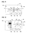
switch 404a on thescreen 430 is pushed, as illustrated inFig. 11 , ascreen 435 illustrating a transition to a stage in which lens processing is able to be performed by thelens processing mechanism 10 is displayed. For example, on thescreen 435, aswitch 402c that inputs a signal for allowing the lensprocessing mechanism section 10 to start processing of the lens LE is displayed. In addition, theswitch 402b that inputs a signal for selecting any of the left and the right of the lens LE to be processed is displayed. Accordingly, the operator may recognize that the stage proceeds to the stage of performing the processing of the lens LE as the next stage. In addition, at the center of ascreen 435, as inFig. 9 , a display for checking the layout data is made. - The operator opens the
window 12 disposed above the lensprocessing mechanism section 10 and holds the lens LE with thelens chuck shafts switch 402a is input, themotor 110 is driven by the control of thecontrol section 50 to move thelens chuck shaft 102R. Thereafter, when theswitch 402c is pushed, thecontrol section 50 executes lens shape measurement using the lensshape measuring unit 200. - After completing the lens shape measurement, when the
switch 404a of thescreen 435 ofFig. 11 is pushed, the screen is switched to ascreen 440 ofFig. 12 . Thescreen 440 is an example of a simulation screen during bevel-processing. On thescreen 440, the target lens shape figure TS, and a figure 442 of a bevel cross-section at the edge position designated by acursor 444 are displayed. The position of thecursor 444 may be changed byswitches screen 440, the operator may confirm whether or not it is appropriate to perform bevel-processing, and conditions of bevel-processing may be changed. In addition, when theswitch 402c is pushed again, driving of theX-direction moving unit 100b and the Y-direction moving unit 100c is controlled, and processing of the peripheral edge of the lens LE is performed by thelens processing tool 168. - As such, since screens in a predetermined order according to the operation processes including rim shape measurement, cup attaching, and lens processing are sequentially switched and displayed on the basis of the input signals while the screens are switched, an operator who is unaccustomed to processing may also smoothly work. In addition, by following the switched displays of the screens, inputting of data needed for processing is accurately performed. Accordingly, the operator efficiently performs a series of the works including rim shape measurement, cup attaching, and lens processing.
Claims (9)
- An apparatus including a cup attaching unit (500) for attaching a cup (CU), which is a processing jig, to a surface of an eyeglass lens, the apparatus comprising:a lens support portion for supporting a lens on a reference axis (L01) extending in a vertical direction;a support arm (562) to which an attaching portion (560) to which a base portion of the cup is attached is attached;a moving arm (556) for support the support arm to be rotatable around an axis (X02) extending a lateral direction so that the attaching portion can be directed in a first direction which is a downward direction toward the lens support portion and in a second direction which is an upward direction or a forward direction in which an operation is positioned with respect to the apparatus; anda lever (564) configured to be operated by the operation and rotate the support arm so as to direct the attaching portion in from the second direction to the first direction,wherein the lever (564) is provided at the support arm and lowers the attaching portion together with the moving arm (556) after the attaching portion is directed in the first direction.
- The apparatus according to claim 1, wherein the cup attaching portion includes:first urging means (555) for urging the moving arm upwardly;second urging means (559) for applying urging force to rotate the support arm so that the attaching portion is directed in from the first direction to the second direction; andrestricting means (570) for restricting the rotation of the support arm so that a center of the attaching portion is positioned above the reference axis when the support arm is rotated so as to direct the attaching portion in the first direction.
- The apparatus according to claim 2, wherein urging force of the first urging means is larger than that of the second urging means.
- The apparatus according to any one of claims 1 to 3, wherein the second direction is a direction in a range of a direction rotated toward the operator side by 45 degrees to 180 degrees with respect to the downward direction of the reference axis.
- The apparatus according to any one of claims 1 to 4, wherein the lever is arranged so as to extend in a substantially horizontal direction when the attaching portion is directed in the first direction.
- The apparatus according to any one of claims 1 to 5 further comprising:a processing apparatus body (1) having a housing where a lens processing mechanism (10) having a processing tool for processing a periphery of the eyeglass lens held by a lens chuck shaft (102L, 102R) is arranged,a display unit (40) arranged in the housing;a signal input unit (40, 404a) for inputting a switching signal for switching a screen of the display unit to a next process step screen;a control unit (50) for controlling the display unit, based on the switching signal, to display, in a predetermined order, a screen (425) to which data for a layout of a positional relationship of the lens with respect to a target lens shape is input, a screen (430) illustrating a transition to a cup attaching process by the cup attaching unit, and a screen (435) illustrating a transition to a stage in which lens processing is able to be performed by the lens processing mechanism.
- The apparatus according to claim 6, wherein
the processing apparatus body includes a base (170) to which the lens processing mechanism is mounted, and
the cup attaching unit is mounted on the base, and is integrally arranged with the processing apparatus body. - The apparatus according to claim 6 or 7, wherein
the cup attaching unit includes imaging means (534) for imaging the lens,
the control unit controls the display unit to display a lens image imaged by the imaging means and superimposes a figure of the target lens shape on the lens image. - The apparatus according to any one of claims 6 to 8 further comprising:an eyeglass frame shape measuring unit for obtaining the target lens shape by measuring a shape of a rim of an eyeglass frame, anda window configured to be opened and closed, the window being provided at an upper surface of the housing to take the eyeglass lens in and out of the lens processing mechanism,wherein the eyeglass frame shape measuring unit is arranged behind the display unit, the cup attaching unit is arranged in front of the display unit, and the window is arranged at a side of the display unit.
Applications Claiming Priority (2)
| Application Number | Priority Date | Filing Date | Title |
|---|---|---|---|
| JP2012053862 | 2012-03-09 | ||
| JP2013036693A JP6338039B2 (en) | 2012-03-09 | 2013-02-27 | Device with cup mounting unit |
Publications (3)
| Publication Number | Publication Date |
|---|---|
| EP2636481A2 true EP2636481A2 (en) | 2013-09-11 |
| EP2636481A3 EP2636481A3 (en) | 2013-12-04 |
| EP2636481B1 EP2636481B1 (en) | 2014-11-26 |
Family
ID=47900438
Family Applications (1)
| Application Number | Title | Priority Date | Filing Date |
|---|---|---|---|
| EP13001140.6A Active EP2636481B1 (en) | 2012-03-09 | 2013-03-07 | Apparatus having cup attaching unit |
Country Status (4)
| Country | Link |
|---|---|
| US (1) | US9421720B2 (en) |
| EP (1) | EP2636481B1 (en) |
| JP (1) | JP6338039B2 (en) |
| CN (2) | CN103302568A (en) |
Cited By (1)
| Publication number | Priority date | Publication date | Assignee | Title |
|---|---|---|---|---|
| EP3495093A1 (en) * | 2017-12-05 | 2019-06-12 | Nidek Co., Ltd. | Shaft alignment apparatus, lens processing apparatus, eyeglasses lens processing system, and eyeglasses lens processing method |
Families Citing this family (7)
| Publication number | Priority date | Publication date | Assignee | Title |
|---|---|---|---|---|
| ITMI20131758A1 (en) | 2013-10-22 | 2015-04-23 | Mei S R L | PROCESS OF PROCESSING A LENS |
| KR102141448B1 (en) * | 2014-06-17 | 2020-08-05 | 가부시키가이샤 니데크 | Apparatus having means for attaching cup |
| EP3409419B1 (en) * | 2014-12-19 | 2022-03-30 | Schneider GmbH & Co. KG | Method and device for machining the edge of an optical lens |
| US10627799B2 (en) | 2015-09-30 | 2020-04-21 | Nidek Co., Ltd. | Terminal device and terminal control program |
| JP7143652B2 (en) | 2018-07-02 | 2022-09-29 | 株式会社ニデック | Eyeglass measurement system and eyeglass measurement program |
| JP7268308B2 (en) * | 2018-09-03 | 2023-05-08 | 株式会社ニデック | cup mounting device |
| CN121586632A (en) | 2023-08-01 | 2026-02-27 | 尼德克株式会社 | Spectacle lens processing device and mounting unit mounted on spectacle lens processing device |
Citations (3)
| Publication number | Priority date | Publication date | Assignee | Title |
|---|---|---|---|---|
| JP2000314617A (en) | 1999-04-30 | 2000-11-14 | Nidek Co Ltd | Spectacles frame-shape measuring device and spectacles lens working device having the device |
| JP2007275998A (en) | 2006-04-03 | 2007-10-25 | Nidek Co Ltd | Cup mounting device |
| JP2008246634A (en) | 2007-03-30 | 2008-10-16 | Nidek Co Ltd | Cup mounting device |
Family Cites Families (14)
| Publication number | Priority date | Publication date | Assignee | Title |
|---|---|---|---|---|
| JPS5617151Y2 (en) * | 1972-11-17 | 1981-04-21 | ||
| DE2931723A1 (en) | 1979-08-04 | 1981-02-19 | Wernicke & Co Gmbh | DEVICE FOR DECENTRATING CORRECTIVE EYE GLASSES AND ATTACHING A HOLDING PART |
| JP3110030B2 (en) * | 1990-03-16 | 2000-11-20 | 株式会社ニデック | Eyeglass lens grinding machine |
| US6798501B1 (en) * | 1998-01-30 | 2004-09-28 | Nidek Co., Ltd. | Cup attaching apparatus |
| JP3929595B2 (en) * | 1998-03-31 | 2007-06-13 | 株式会社ニデック | Eyeglass lens processing system |
| JP4442846B2 (en) * | 2000-12-15 | 2010-03-31 | 株式会社トプコン | Processing order system for eyeglass lenses |
| JP3966696B2 (en) | 2001-03-26 | 2007-08-29 | 株式会社ニデック | Cup mounting device |
| ATE433826T1 (en) | 2002-01-09 | 2009-07-15 | Hoya Corp | GRINDING TOOL |
| US7715023B2 (en) | 2004-03-31 | 2010-05-11 | Kabushiki Kaisha Topcon | Jig mounting apparatus |
| CN100587553C (en) | 2004-03-31 | 2010-02-03 | 株式会社拓普康 | Automatic jig installation device for spectacle lens and automatic jig installation method |
| JP2007152439A (en) * | 2005-11-30 | 2007-06-21 | Nidek Co Ltd | Spectacle lens machining device |
| JP4699243B2 (en) * | 2006-02-28 | 2011-06-08 | 株式会社ニデック | Layout setting device for spectacle lens peripheral processing and spectacle lens peripheral processing system |
| JP5085922B2 (en) * | 2006-11-30 | 2012-11-28 | 株式会社ニデック | Eyeglass lens processing system |
| JP5453354B2 (en) * | 2011-07-04 | 2014-03-26 | シャープ株式会社 | Production management system, production management method, control program, and readable storage medium |
-
2013
- 2013-02-27 JP JP2013036693A patent/JP6338039B2/en active Active
- 2013-03-07 US US13/788,439 patent/US9421720B2/en active Active
- 2013-03-07 EP EP13001140.6A patent/EP2636481B1/en active Active
- 2013-03-11 CN CN2013100765579A patent/CN103302568A/en active Pending
- 2013-03-11 CN CN201710532489.0A patent/CN107253112B/en active Active
Patent Citations (3)
| Publication number | Priority date | Publication date | Assignee | Title |
|---|---|---|---|---|
| JP2000314617A (en) | 1999-04-30 | 2000-11-14 | Nidek Co Ltd | Spectacles frame-shape measuring device and spectacles lens working device having the device |
| JP2007275998A (en) | 2006-04-03 | 2007-10-25 | Nidek Co Ltd | Cup mounting device |
| JP2008246634A (en) | 2007-03-30 | 2008-10-16 | Nidek Co Ltd | Cup mounting device |
Cited By (1)
| Publication number | Priority date | Publication date | Assignee | Title |
|---|---|---|---|---|
| EP3495093A1 (en) * | 2017-12-05 | 2019-06-12 | Nidek Co., Ltd. | Shaft alignment apparatus, lens processing apparatus, eyeglasses lens processing system, and eyeglasses lens processing method |
Also Published As
| Publication number | Publication date |
|---|---|
| EP2636481A3 (en) | 2013-12-04 |
| US20130236585A1 (en) | 2013-09-12 |
| CN107253112A (en) | 2017-10-17 |
| JP2013212573A (en) | 2013-10-17 |
| JP6338039B2 (en) | 2018-06-06 |
| CN107253112B (en) | 2021-03-30 |
| EP2636481B1 (en) | 2014-11-26 |
| CN103302568A (en) | 2013-09-18 |
| US9421720B2 (en) | 2016-08-23 |
Similar Documents
| Publication | Publication Date | Title |
|---|---|---|
| EP2636481B1 (en) | Apparatus having cup attaching unit | |
| JP4920284B2 (en) | Cup mounting device | |
| KR101423768B1 (en) | Eyeglass lens processing system | |
| KR101381121B1 (en) | Cup attaching apparatus | |
| US7532315B2 (en) | Automatic lens blocking apparatus | |
| JP2014233788A (en) | Spectacle lens processing device and spectacle lens vertical direction detection program | |
| JP2019060651A (en) | Lens characteristic measuring device | |
| KR20070099434A (en) | Cup mounting device | |
| US9421658B2 (en) | Apparatus having cup attaching unit | |
| JP4104297B2 (en) | Cup mounting device | |
| KR102141448B1 (en) | Apparatus having means for attaching cup | |
| JP7087366B2 (en) | Axis setting device, spectacle lens processing system, and spectacle lens processing method | |
| JP7172029B2 (en) | Alignment device | |
| JP2019211213A (en) | Lens shape measurement apparatus | |
| KR101497691B1 (en) | Glasses lens processing equipment | |
| JP2026046893A (en) | Step formation data setting device, step formation data setting program, and spectacle lens rim processing device | |
| JP7243706B2 (en) | Lens shape acquisition device | |
| JP4593648B2 (en) | Lens shape data processing device | |
| JP2019209380A (en) | Spectacle lens processing control data acquisition device | |
| JPH09248746A (en) | Collimating machine | |
| JP2024145241A (en) | Centering device and centering program | |
| JP2024145240A (en) | Centering device and centering program | |
| JP4688827B2 (en) | Method and apparatus for tilting bevel | |
| JP2001315046A (en) | Eyeglass lens bevel shape data processing apparatus and lens grinding apparatus having the same |
Legal Events
| Date | Code | Title | Description |
|---|---|---|---|
| PUAI | Public reference made under article 153(3) epc to a published international application that has entered the european phase |
Free format text: ORIGINAL CODE: 0009012 |
|
| AK | Designated contracting states |
Kind code of ref document: A2 Designated state(s): AL AT BE BG CH CY CZ DE DK EE ES FI FR GB GR HR HU IE IS IT LI LT LU LV MC MK MT NL NO PL PT RO RS SE SI SK SM TR |
|
| AX | Request for extension of the european patent |
Extension state: BA ME |
|
| PUAL | Search report despatched |
Free format text: ORIGINAL CODE: 0009013 |
|
| AK | Designated contracting states |
Kind code of ref document: A3 Designated state(s): AL AT BE BG CH CY CZ DE DK EE ES FI FR GB GR HR HU IE IS IT LI LT LU LV MC MK MT NL NO PL PT RO RS SE SI SK SM TR |
|
| AX | Request for extension of the european patent |
Extension state: BA ME |
|
| RIC1 | Information provided on ipc code assigned before grant |
Ipc: B24B 13/005 20060101AFI20131029BHEP Ipc: B24B 9/14 20060101ALI20131029BHEP |
|
| GRAP | Despatch of communication of intention to grant a patent |
Free format text: ORIGINAL CODE: EPIDOSNIGR1 |
|
| 17P | Request for examination filed |
Effective date: 20140523 |
|
| RBV | Designated contracting states (corrected) |
Designated state(s): AL AT BE BG CH CY CZ DE DK EE ES FI FR GB GR HR HU IE IS IT LI LT LU LV MC MK MT NL NO PL PT RO RS SE SI SK SM TR |
|
| INTG | Intention to grant announced |
Effective date: 20140702 |
|
| GRAS | Grant fee paid |
Free format text: ORIGINAL CODE: EPIDOSNIGR3 |
|
| GRAA | (expected) grant |
Free format text: ORIGINAL CODE: 0009210 |
|
| AK | Designated contracting states |
Kind code of ref document: B1 Designated state(s): AL AT BE BG CH CY CZ DE DK EE ES FI FR GB GR HR HU IE IS IT LI LT LU LV MC MK MT NL NO PL PT RO RS SE SI SK SM TR |
|
| REG | Reference to a national code |
Ref country code: GB Ref legal event code: FG4D |
|
| REG | Reference to a national code |
Ref country code: CH Ref legal event code: EP |
|
| REG | Reference to a national code |
Ref country code: AT Ref legal event code: REF Ref document number: 697896 Country of ref document: AT Kind code of ref document: T Effective date: 20141215 |
|
| REG | Reference to a national code |
Ref country code: IE Ref legal event code: FG4D |
|
| REG | Reference to a national code |
Ref country code: DE Ref legal event code: R096 Ref document number: 602013000499 Country of ref document: DE Effective date: 20150115 |
|
| REG | Reference to a national code |
Ref country code: NL Ref legal event code: VDEP Effective date: 20141126 |
|
| REG | Reference to a national code |
Ref country code: AT Ref legal event code: MK05 Ref document number: 697896 Country of ref document: AT Kind code of ref document: T Effective date: 20141126 |
|
| REG | Reference to a national code |
Ref country code: LT Ref legal event code: MG4D |
|
| PG25 | Lapsed in a contracting state [announced via postgrant information from national office to epo] |
Ref country code: PT Free format text: LAPSE BECAUSE OF FAILURE TO SUBMIT A TRANSLATION OF THE DESCRIPTION OR TO PAY THE FEE WITHIN THE PRESCRIBED TIME-LIMIT Effective date: 20150326 Ref country code: LT Free format text: LAPSE BECAUSE OF FAILURE TO SUBMIT A TRANSLATION OF THE DESCRIPTION OR TO PAY THE FEE WITHIN THE PRESCRIBED TIME-LIMIT Effective date: 20141126 Ref country code: ES Free format text: LAPSE BECAUSE OF FAILURE TO SUBMIT A TRANSLATION OF THE DESCRIPTION OR TO PAY THE FEE WITHIN THE PRESCRIBED TIME-LIMIT Effective date: 20141126 Ref country code: NL Free format text: LAPSE BECAUSE OF FAILURE TO SUBMIT A TRANSLATION OF THE DESCRIPTION OR TO PAY THE FEE WITHIN THE PRESCRIBED TIME-LIMIT Effective date: 20141126 Ref country code: IS Free format text: LAPSE BECAUSE OF FAILURE TO SUBMIT A TRANSLATION OF THE DESCRIPTION OR TO PAY THE FEE WITHIN THE PRESCRIBED TIME-LIMIT Effective date: 20150326 Ref country code: NO Free format text: LAPSE BECAUSE OF FAILURE TO SUBMIT A TRANSLATION OF THE DESCRIPTION OR TO PAY THE FEE WITHIN THE PRESCRIBED TIME-LIMIT Effective date: 20150226 Ref country code: FI Free format text: LAPSE BECAUSE OF FAILURE TO SUBMIT A TRANSLATION OF THE DESCRIPTION OR TO PAY THE FEE WITHIN THE PRESCRIBED TIME-LIMIT Effective date: 20141126 |
|
| PG25 | Lapsed in a contracting state [announced via postgrant information from national office to epo] |
Ref country code: CY Free format text: LAPSE BECAUSE OF FAILURE TO SUBMIT A TRANSLATION OF THE DESCRIPTION OR TO PAY THE FEE WITHIN THE PRESCRIBED TIME-LIMIT Effective date: 20141126 Ref country code: LV Free format text: LAPSE BECAUSE OF FAILURE TO SUBMIT A TRANSLATION OF THE DESCRIPTION OR TO PAY THE FEE WITHIN THE PRESCRIBED TIME-LIMIT Effective date: 20141126 Ref country code: HR Free format text: LAPSE BECAUSE OF FAILURE TO SUBMIT A TRANSLATION OF THE DESCRIPTION OR TO PAY THE FEE WITHIN THE PRESCRIBED TIME-LIMIT Effective date: 20141126 Ref country code: SE Free format text: LAPSE BECAUSE OF FAILURE TO SUBMIT A TRANSLATION OF THE DESCRIPTION OR TO PAY THE FEE WITHIN THE PRESCRIBED TIME-LIMIT Effective date: 20141126 Ref country code: AT Free format text: LAPSE BECAUSE OF FAILURE TO SUBMIT A TRANSLATION OF THE DESCRIPTION OR TO PAY THE FEE WITHIN THE PRESCRIBED TIME-LIMIT Effective date: 20141126 Ref country code: RS Free format text: LAPSE BECAUSE OF FAILURE TO SUBMIT A TRANSLATION OF THE DESCRIPTION OR TO PAY THE FEE WITHIN THE PRESCRIBED TIME-LIMIT Effective date: 20141126 Ref country code: GR Free format text: LAPSE BECAUSE OF FAILURE TO SUBMIT A TRANSLATION OF THE DESCRIPTION OR TO PAY THE FEE WITHIN THE PRESCRIBED TIME-LIMIT Effective date: 20150227 |
|
| PG25 | Lapsed in a contracting state [announced via postgrant information from national office to epo] |
Ref country code: EE Free format text: LAPSE BECAUSE OF FAILURE TO SUBMIT A TRANSLATION OF THE DESCRIPTION OR TO PAY THE FEE WITHIN THE PRESCRIBED TIME-LIMIT Effective date: 20141126 Ref country code: SK Free format text: LAPSE BECAUSE OF FAILURE TO SUBMIT A TRANSLATION OF THE DESCRIPTION OR TO PAY THE FEE WITHIN THE PRESCRIBED TIME-LIMIT Effective date: 20141126 Ref country code: DK Free format text: LAPSE BECAUSE OF FAILURE TO SUBMIT A TRANSLATION OF THE DESCRIPTION OR TO PAY THE FEE WITHIN THE PRESCRIBED TIME-LIMIT Effective date: 20141126 Ref country code: RO Free format text: LAPSE BECAUSE OF FAILURE TO SUBMIT A TRANSLATION OF THE DESCRIPTION OR TO PAY THE FEE WITHIN THE PRESCRIBED TIME-LIMIT Effective date: 20141126 Ref country code: CZ Free format text: LAPSE BECAUSE OF FAILURE TO SUBMIT A TRANSLATION OF THE DESCRIPTION OR TO PAY THE FEE WITHIN THE PRESCRIBED TIME-LIMIT Effective date: 20141126 |
|
| REG | Reference to a national code |
Ref country code: DE Ref legal event code: R097 Ref document number: 602013000499 Country of ref document: DE |
|
| PG25 | Lapsed in a contracting state [announced via postgrant information from national office to epo] |
Ref country code: PL Free format text: LAPSE BECAUSE OF FAILURE TO SUBMIT A TRANSLATION OF THE DESCRIPTION OR TO PAY THE FEE WITHIN THE PRESCRIBED TIME-LIMIT Effective date: 20141126 |
|
| PLBE | No opposition filed within time limit |
Free format text: ORIGINAL CODE: 0009261 |
|
| STAA | Information on the status of an ep patent application or granted ep patent |
Free format text: STATUS: NO OPPOSITION FILED WITHIN TIME LIMIT |
|
| PG25 | Lapsed in a contracting state [announced via postgrant information from national office to epo] |
Ref country code: LU Free format text: LAPSE BECAUSE OF FAILURE TO SUBMIT A TRANSLATION OF THE DESCRIPTION OR TO PAY THE FEE WITHIN THE PRESCRIBED TIME-LIMIT Effective date: 20150307 Ref country code: MC Free format text: LAPSE BECAUSE OF FAILURE TO SUBMIT A TRANSLATION OF THE DESCRIPTION OR TO PAY THE FEE WITHIN THE PRESCRIBED TIME-LIMIT Effective date: 20141126 |
|
| 26N | No opposition filed |
Effective date: 20150827 |
|
| PG25 | Lapsed in a contracting state [announced via postgrant information from national office to epo] |
Ref country code: IT Free format text: LAPSE BECAUSE OF FAILURE TO SUBMIT A TRANSLATION OF THE DESCRIPTION OR TO PAY THE FEE WITHIN THE PRESCRIBED TIME-LIMIT Effective date: 20141126 |
|
| REG | Reference to a national code |
Ref country code: IE Ref legal event code: MM4A |
|
| PG25 | Lapsed in a contracting state [announced via postgrant information from national office to epo] |
Ref country code: IE Free format text: LAPSE BECAUSE OF NON-PAYMENT OF DUE FEES Effective date: 20150307 |
|
| REG | Reference to a national code |
Ref country code: FR Ref legal event code: PLFP Year of fee payment: 4 |
|
| PG25 | Lapsed in a contracting state [announced via postgrant information from national office to epo] |
Ref country code: SI Free format text: LAPSE BECAUSE OF FAILURE TO SUBMIT A TRANSLATION OF THE DESCRIPTION OR TO PAY THE FEE WITHIN THE PRESCRIBED TIME-LIMIT Effective date: 20141126 |
|
| REG | Reference to a national code |
Ref country code: CH Ref legal event code: PL |
|
| PG25 | Lapsed in a contracting state [announced via postgrant information from national office to epo] |
Ref country code: MT Free format text: LAPSE BECAUSE OF FAILURE TO SUBMIT A TRANSLATION OF THE DESCRIPTION OR TO PAY THE FEE WITHIN THE PRESCRIBED TIME-LIMIT Effective date: 20141126 |
|
| PG25 | Lapsed in a contracting state [announced via postgrant information from national office to epo] |
Ref country code: CH Free format text: LAPSE BECAUSE OF NON-PAYMENT OF DUE FEES Effective date: 20160331 Ref country code: LI Free format text: LAPSE BECAUSE OF NON-PAYMENT OF DUE FEES Effective date: 20160331 |
|
| REG | Reference to a national code |
Ref country code: FR Ref legal event code: PLFP Year of fee payment: 5 |
|
| PG25 | Lapsed in a contracting state [announced via postgrant information from national office to epo] |
Ref country code: BG Free format text: LAPSE BECAUSE OF FAILURE TO SUBMIT A TRANSLATION OF THE DESCRIPTION OR TO PAY THE FEE WITHIN THE PRESCRIBED TIME-LIMIT Effective date: 20141126 Ref country code: HU Free format text: LAPSE BECAUSE OF FAILURE TO SUBMIT A TRANSLATION OF THE DESCRIPTION OR TO PAY THE FEE WITHIN THE PRESCRIBED TIME-LIMIT; INVALID AB INITIO Effective date: 20130307 |
|
| PG25 | Lapsed in a contracting state [announced via postgrant information from national office to epo] |
Ref country code: TR Free format text: LAPSE BECAUSE OF FAILURE TO SUBMIT A TRANSLATION OF THE DESCRIPTION OR TO PAY THE FEE WITHIN THE PRESCRIBED TIME-LIMIT Effective date: 20141126 |
|
| PG25 | Lapsed in a contracting state [announced via postgrant information from national office to epo] |
Ref country code: BE Free format text: LAPSE BECAUSE OF FAILURE TO SUBMIT A TRANSLATION OF THE DESCRIPTION OR TO PAY THE FEE WITHIN THE PRESCRIBED TIME-LIMIT Effective date: 20141126 |
|
| REG | Reference to a national code |
Ref country code: FR Ref legal event code: PLFP Year of fee payment: 6 |
|
| PG25 | Lapsed in a contracting state [announced via postgrant information from national office to epo] |
Ref country code: SM Free format text: LAPSE BECAUSE OF FAILURE TO SUBMIT A TRANSLATION OF THE DESCRIPTION OR TO PAY THE FEE WITHIN THE PRESCRIBED TIME-LIMIT Effective date: 20141126 |
|
| PG25 | Lapsed in a contracting state [announced via postgrant information from national office to epo] |
Ref country code: MK Free format text: LAPSE BECAUSE OF FAILURE TO SUBMIT A TRANSLATION OF THE DESCRIPTION OR TO PAY THE FEE WITHIN THE PRESCRIBED TIME-LIMIT Effective date: 20141126 |
|
| PG25 | Lapsed in a contracting state [announced via postgrant information from national office to epo] |
Ref country code: AL Free format text: LAPSE BECAUSE OF FAILURE TO SUBMIT A TRANSLATION OF THE DESCRIPTION OR TO PAY THE FEE WITHIN THE PRESCRIBED TIME-LIMIT Effective date: 20141126 |
|
| P01 | Opt-out of the competence of the unified patent court (upc) registered |
Effective date: 20230509 |
|
| PGFP | Annual fee paid to national office [announced via postgrant information from national office to epo] |
Ref country code: DE Payment date: 20240130 Year of fee payment: 12 Ref country code: GB Payment date: 20240201 Year of fee payment: 12 |
|
| REG | Reference to a national code |
Ref country code: DE Ref legal event code: R119 Ref document number: 602013000499 Country of ref document: DE |
|
| GBPC | Gb: european patent ceased through non-payment of renewal fee |
Effective date: 20250307 |
|
| PG25 | Lapsed in a contracting state [announced via postgrant information from national office to epo] |
Ref country code: DE Free format text: LAPSE BECAUSE OF NON-PAYMENT OF DUE FEES Effective date: 20251001 |
|
| PG25 | Lapsed in a contracting state [announced via postgrant information from national office to epo] |
Ref country code: GB Free format text: LAPSE BECAUSE OF NON-PAYMENT OF DUE FEES Effective date: 20250307 |
|
| PGFP | Annual fee paid to national office [announced via postgrant information from national office to epo] |
Ref country code: FR Payment date: 20260209 Year of fee payment: 14 |