EP2634831A1 - Pouch type secondary battery - Google Patents
Pouch type secondary battery Download PDFInfo
- Publication number
- EP2634831A1 EP2634831A1 EP13157182.0A EP13157182A EP2634831A1 EP 2634831 A1 EP2634831 A1 EP 2634831A1 EP 13157182 A EP13157182 A EP 13157182A EP 2634831 A1 EP2634831 A1 EP 2634831A1
- Authority
- EP
- European Patent Office
- Prior art keywords
- secondary battery
- pouch
- insulating member
- sealing portion
- type secondary
- Prior art date
- Legal status (The legal status is an assumption and is not a legal conclusion. Google has not performed a legal analysis and makes no representation as to the accuracy of the status listed.)
- Granted
Links
Images


Classifications
-
- H—ELECTRICITY
- H01—ELECTRIC ELEMENTS
- H01M—PROCESSES OR MEANS, e.g. BATTERIES, FOR THE DIRECT CONVERSION OF CHEMICAL ENERGY INTO ELECTRICAL ENERGY
- H01M50/00—Constructional details or processes of manufacture of the non-active parts of electrochemical cells other than fuel cells, e.g. hybrid cells
- H01M50/10—Primary casings; Jackets or wrappings
- H01M50/147—Lids or covers
- H01M50/166—Lids or covers characterised by the methods of assembling casings with lids
- H01M50/171—Lids or covers characterised by the methods of assembling casings with lids using adhesives or sealing agents
-
- H—ELECTRICITY
- H01—ELECTRIC ELEMENTS
- H01M—PROCESSES OR MEANS, e.g. BATTERIES, FOR THE DIRECT CONVERSION OF CHEMICAL ENERGY INTO ELECTRICAL ENERGY
- H01M50/00—Constructional details or processes of manufacture of the non-active parts of electrochemical cells other than fuel cells, e.g. hybrid cells
- H01M50/10—Primary casings; Jackets or wrappings
- H01M50/102—Primary casings; Jackets or wrappings characterised by their shape or physical structure
- H01M50/105—Pouches or flexible bags
-
- H—ELECTRICITY
- H01—ELECTRIC ELEMENTS
- H01M—PROCESSES OR MEANS, e.g. BATTERIES, FOR THE DIRECT CONVERSION OF CHEMICAL ENERGY INTO ELECTRICAL ENERGY
- H01M50/00—Constructional details or processes of manufacture of the non-active parts of electrochemical cells other than fuel cells, e.g. hybrid cells
- H01M50/10—Primary casings; Jackets or wrappings
- H01M50/116—Primary casings; Jackets or wrappings characterised by the material
- H01M50/117—Inorganic material
- H01M50/119—Metals
-
- H—ELECTRICITY
- H01—ELECTRIC ELEMENTS
- H01M—PROCESSES OR MEANS, e.g. BATTERIES, FOR THE DIRECT CONVERSION OF CHEMICAL ENERGY INTO ELECTRICAL ENERGY
- H01M50/00—Constructional details or processes of manufacture of the non-active parts of electrochemical cells other than fuel cells, e.g. hybrid cells
- H01M50/10—Primary casings; Jackets or wrappings
- H01M50/116—Primary casings; Jackets or wrappings characterised by the material
- H01M50/121—Organic material
-
- H—ELECTRICITY
- H01—ELECTRIC ELEMENTS
- H01M—PROCESSES OR MEANS, e.g. BATTERIES, FOR THE DIRECT CONVERSION OF CHEMICAL ENERGY INTO ELECTRICAL ENERGY
- H01M50/00—Constructional details or processes of manufacture of the non-active parts of electrochemical cells other than fuel cells, e.g. hybrid cells
- H01M50/10—Primary casings; Jackets or wrappings
- H01M50/116—Primary casings; Jackets or wrappings characterised by the material
- H01M50/124—Primary casings; Jackets or wrappings characterised by the material having a layered structure
- H01M50/126—Primary casings; Jackets or wrappings characterised by the material having a layered structure comprising three or more layers
- H01M50/129—Primary casings; Jackets or wrappings characterised by the material having a layered structure comprising three or more layers with two or more layers of only organic material
-
- H—ELECTRICITY
- H01—ELECTRIC ELEMENTS
- H01M—PROCESSES OR MEANS, e.g. BATTERIES, FOR THE DIRECT CONVERSION OF CHEMICAL ENERGY INTO ELECTRICAL ENERGY
- H01M50/00—Constructional details or processes of manufacture of the non-active parts of electrochemical cells other than fuel cells, e.g. hybrid cells
- H01M50/10—Primary casings; Jackets or wrappings
- H01M50/131—Primary casings; Jackets or wrappings characterised by physical properties, e.g. gas permeability, size or heat resistance
- H01M50/136—Flexibility or foldability
-
- H—ELECTRICITY
- H01—ELECTRIC ELEMENTS
- H01M—PROCESSES OR MEANS, e.g. BATTERIES, FOR THE DIRECT CONVERSION OF CHEMICAL ENERGY INTO ELECTRICAL ENERGY
- H01M50/00—Constructional details or processes of manufacture of the non-active parts of electrochemical cells other than fuel cells, e.g. hybrid cells
- H01M50/10—Primary casings; Jackets or wrappings
- H01M50/172—Arrangements of electric connectors penetrating the casing
- H01M50/174—Arrangements of electric connectors penetrating the casing adapted for the shape of the cells
- H01M50/178—Arrangements of electric connectors penetrating the casing adapted for the shape of the cells for pouch or flexible bag cells
-
- H—ELECTRICITY
- H01—ELECTRIC ELEMENTS
- H01M—PROCESSES OR MEANS, e.g. BATTERIES, FOR THE DIRECT CONVERSION OF CHEMICAL ENERGY INTO ELECTRICAL ENERGY
- H01M50/00—Constructional details or processes of manufacture of the non-active parts of electrochemical cells other than fuel cells, e.g. hybrid cells
- H01M50/50—Current conducting connections for cells or batteries
- H01M50/543—Terminals
- H01M50/547—Terminals characterised by the disposition of the terminals on the cells
- H01M50/55—Terminals characterised by the disposition of the terminals on the cells on the same side of the cell
-
- Y—GENERAL TAGGING OF NEW TECHNOLOGICAL DEVELOPMENTS; GENERAL TAGGING OF CROSS-SECTIONAL TECHNOLOGIES SPANNING OVER SEVERAL SECTIONS OF THE IPC; TECHNICAL SUBJECTS COVERED BY FORMER USPC CROSS-REFERENCE ART COLLECTIONS [XRACs] AND DIGESTS
- Y02—TECHNOLOGIES OR APPLICATIONS FOR MITIGATION OR ADAPTATION AGAINST CLIMATE CHANGE
- Y02E—REDUCTION OF GREENHOUSE GAS [GHG] EMISSIONS, RELATED TO ENERGY GENERATION, TRANSMISSION OR DISTRIBUTION
- Y02E60/00—Enabling technologies; Technologies with a potential or indirect contribution to GHG emissions mitigation
- Y02E60/10—Energy storage using batteries
-
- Y—GENERAL TAGGING OF NEW TECHNOLOGICAL DEVELOPMENTS; GENERAL TAGGING OF CROSS-SECTIONAL TECHNOLOGIES SPANNING OVER SEVERAL SECTIONS OF THE IPC; TECHNICAL SUBJECTS COVERED BY FORMER USPC CROSS-REFERENCE ART COLLECTIONS [XRACs] AND DIGESTS
- Y02—TECHNOLOGIES OR APPLICATIONS FOR MITIGATION OR ADAPTATION AGAINST CLIMATE CHANGE
- Y02P—CLIMATE CHANGE MITIGATION TECHNOLOGIES IN THE PRODUCTION OR PROCESSING OF GOODS
- Y02P70/00—Climate change mitigation technologies in the production process for final industrial or consumer products
- Y02P70/50—Manufacturing or production processes characterised by the final manufactured product
-
- Y—GENERAL TAGGING OF NEW TECHNOLOGICAL DEVELOPMENTS; GENERAL TAGGING OF CROSS-SECTIONAL TECHNOLOGIES SPANNING OVER SEVERAL SECTIONS OF THE IPC; TECHNICAL SUBJECTS COVERED BY FORMER USPC CROSS-REFERENCE ART COLLECTIONS [XRACs] AND DIGESTS
- Y10—TECHNICAL SUBJECTS COVERED BY FORMER USPC
- Y10T—TECHNICAL SUBJECTS COVERED BY FORMER US CLASSIFICATION
- Y10T29/00—Metal working
- Y10T29/49—Method of mechanical manufacture
- Y10T29/49002—Electrical device making
- Y10T29/49108—Electric battery cell making
- Y10T29/4911—Electric battery cell making including sealing
Definitions
- the present invention relates to a secondary battery, and more particularly, to a pouch-type secondary battery having improved safety.
- secondary batteries have been variously used as power sources of portable electronic devices.
- portable electronic devices are used in various fields, a demand on secondary batteries rapidly increases.
- the secondary battery is rechargeable and thus can be used plural times. Therefore, the secondary battery is economically and environmentally effective, and thus the use of the secondary battery is promoted.
- Embodiments provide a secondary battery having improved safety by employing a new member.
- Embodiments also provide a secondary battery having improved productivity by simplifying a manufacturing process and decreasing a failure rate.
- a pouch-type secondary battery comprising an electrode assembly, a pouch having an accommodating portion for accommodating the electrode assembly and a sealing portion provided along an edge of the accommodating portion and an insulating member around the sealing portion, wherein the sealing portion is folded against the accommodating portion and a bonding member is arranged between the accommodating portion and the sealing portion, wherein the insulating member and the bonding member are integrally provided.
- the insulating member may be folded around an edge of the sealing portion.
- the insulating member may comprise a first wing extending along a first surface of the sealing portion closest to the accommodating portion and a second wing extending along a second surface of the sealing portion opposite the first surface.
- the secondary battery may further comprise a joining portion joining the first and second wings and extending along the edge of the sealing portion.
- the first and second wings of the insulating member may be symmetrically disposed around the edge of the sealing portion.
- the insulating member may cover substantially the whole of the first and second surfaces of the sealing portion.
- the first wing of the insulating member may be wider than the second wing.
- the first wing may cover substantially the whole of the first surface of the sealing portion.
- the insulating member may further comprise a third wing that is arranged to fold onto a top surface of the accommodating portion.
- the third wing may extend from the joining portion in an opposite direction to the first and second wings.
- the pouch may comprise a main body and a cover for covering the accommodating portion, the main body comprising a flange at the top of the accommodating portion, wherein an edge of the cover is bonded to the flange to form the sealing portion.
- the bonding member may be arranged between the first wing and the accommodating portion.
- the bonding member may correspond to a side of the first wing.
- the pouch-type secondary battery 100 includes an electrode assembly 30 having first and second electrode plates and a separator interposed between the electrode plates, a battery case, or pouch, 20 having an accommodating portion 21 for accommodating the electrode assembly 30 and a sealing portion 24 provided along an edge of the accommodating portion 21 and an insulating member 110 provided to surround at least one part of the sealing portion 24.
- the insulating member 110 has a bonding portion, or member, 120 provided thereon.
- the sealing portion 24 is bent toward the accommodating portion 21, and the bonding portion 120 is interposed between the insulating member 110 and the accommodating portion 21 of the battery case 21.
- the insulating member 110 and the bonding portion 120 are integrally provided.
- the pouch-type secondary battery 100 includes the electrode assembly 30 and the battery case 20, and the battery case 20 accommodates the electrode assembly 30 and an electrolyte in the accommodating portion 21 provided to the inside thereof.
- the electrode assembly 30 includes first and second electrode tabs 31 and 32 respectively connected to the first and second electrode plates, and the first and second electrode tabs 31 and 32 may be extracted outward from the electrode assembly 30.
- the first and second electrode plates may be positive and negative electrode plates, respectively.
- the first electrode tab 31 may be provided to the positive electrode plate so as to act as a positive electrode tab
- the second electrode tab 32 may be provided to the negative electrode plate so as to act as a negative electrode tab.
- Electrochemical energy is generated when ions or electrons move between the first and second electrode plates.
- the electrochemical energy may be provided to the outside of the electrode assembly 30 through the first and second electrode tabs 31 and 32.
- Lead films 33 may be provided to the first and second electrode tabs 31 and 32, respectively.
- the electrode assembly 30 may be manufactured using various methods including a method of winding or laminating the first and second electrode plates and the separator together, and the like.
- the battery case 20 may include a main body having the accommodating portion 21 provided thereto and a cover 23 connected to the main body 22 so as to cover the accommodating portion 21.
- the pouch-type secondary battery 100 may be manufactured by accommodating the electrode assembly 30 and the electrolyte in the accommodating portion 21 of the main body 22 and then thermally bonding edges 24a and 24b of the main body 22 and the cover 23 in the state in which the main body 22 and the cover 23 are adhered closely to each other.
- the accommodating portion 21 may be provided to correspond to the shape of the electrode assembly 30.
- the accommodating portion 21 may be provided to the main body 22 through deep drawing in which a hollow container with no joint is made using a flat plate.
- the battery case 20 may be formed with a plurality of layers including an internal resin layer A', a metal layer B and an external resin layer A.
- the internal resin layer A', the metal layer B and the external resin layer A may be provided to be sequentially laminated.
- the internal resin layer A' is a part that directly faces the electrode assembly 30, and the external resin layer A may be provided to the outermost surface of the secondary battery 20.
- the internal and external resin layers A' and A are used to prevent an electrical short circuit, or the like, and may be formed using polymer resin, or the like, which is a non-conductor.
- the metal layer B is provided between the internal and external resin layers A' and A, so as to provide a predetermined mechanical strength to the battery case.
- the metal layer B may include aluminum or the like.
- the first and second electrode tabs 31 and 32 When the first and second electrode tabs 31 and 32 are extracted to the outside of the battery case 20, the first and second electrode tabs 31 and 32 may prevent the sealing portion 24 from being thermally bonded.
- the lead film 33 is settled on the sealing portion 24 of the battery case 20, so that it is possible to prevent the sealing performance of the sealing portion 24 from being lowered.
- the first electrode tab 31 may include aluminum and the second electrode tab 32 may include nickel. While the first electrode tab 31 may have the same polarity as the metal layer B of the battery case 20, the second electrode tab 32 may have the opposite polarity to the metal layer B of the battery case 20. Therefore, when the second electrode tab 32 comes in contact with the metal layer B exposed at an end of the battery case 20, particularly the sealing portion 24, an electrical short circuit may occur. Further, the sealing portion 24 may increase the volume of the pouch-type secondary battery 100, and may cause a problem in the external appearance of the pouch-type secondary battery 100. In order to such a problem, the pouch-type secondary battery 100 according to this embodiment may have the insulating member 110 provided to the sealing portion 24.
- a pouch-type secondary battery is provided with a sealing portion, and the sealing portion may cause a problem of safety, such as a short circuit.
- the sealing portion is insulated.
- the sealing portion is insulated using a plurality of members, and a separate adhesive is used so that the sealing portion is fixed to a battery case.
- the sealing portion is insulated through a multi-step process. This results in a complicated manufacturing process of the pouch-type secondary battery and a failure of the external appearance of the pouch-type secondary battery, and therefore, the productivity of the pouch-type secondary battery is deteriorated.
- This embodiment provides the insulating member 110 which can allow the external appearance of the pouch-type secondary battery 100 to be improved and improve the productivity efficiency of the pouch-type secondary battery 100 by simplifying the manufacturing process of the pouch-type secondary battery 100.
- the insulating member 110 is integrally provided with the bonding portion 120, and thus, the process of insulating the sealing portion 24 and the process of fixing the sealing portion 24 to the battery case 20 are not performed as individual processes but can be collectively performed by one process.
- the insulating member 110 may guide the sealing portion 24 to be fixed at an exact position of the battery case 20, and thus it is possible to improve the productivity and to minimize a failure rate.
- FIG. 4A is an exploded perspective view of an insulating member according to the embodiment of the present invention.
- FIG. 4B is a perspective view of the insulating member according to the embodiment of the present invention.
- FIG. 5 is an extended view of part X of FIG. 1 .
- the insulating member 110 may be provided to surround one and the other surfaces of the sealing portion 24.
- the insulating member 110 includes a buffer portion, also referred to as a joining portion, 113 provided to an inside thereof, and the buffer portion 113 may be provided to correspond to an end of the sealing portion 24.
- the width of the buffer portion 113 may be provided to correspond to the thickness of the sealing portion 24.
- the insulating member 110 may be divided into first and second portions 111 and 112 with the buffer portion 113 at the centre joining the first and second portions, which are also referred to herein as first and second wings. In this case, the first and second portions 111 and 112 may be provided to have the same size.
- Folding lines 113a may be provided between the buffer portion 113 and the first and second portions 111 and 112, respectively, and the first and second portions 111 and 112 may be bent in the same direction based on the folding lines 113a.
- the first and second portions 111 and 112 of the insulating member 110 are provided to surround the sealing portion 24, and may be provided to have a size corresponding to that of the sealing portion 24.
- the sealing portion 24 may be bent to the main body 22 so as to decrease the volume of the pouch-type secondary battery 100. That is, the sealing portion 24 having the insulating member 110 may be bent to come in contact with the outside of the accommodating portion 21 of the battery case 20.
- the insulating member 110 is integrally provided with the bonding portion 120, and the bonding portion 120 enables the sealing portion 24 to be firmly fixed to the battery case 20.
- FIGS. 6A to 7B components, except the following description, are similar to those in the embodiment described in FIGS. 1 to 5 , and therefore, their detailed descriptions will be omitted.
- FIG. 6A is an exploded perspective view of an insulating member according to another embodiment of the present invention.
- FIG. 6B is a plan view of a pouch-type secondary battery according to the embodiment of the present invention.
- a sealing portion 24 of the battery case 20 may be provided so that at least one part of the sealing portion 24 is surrounded by an insulating member 210.
- the insulating member 210 further includes a bonding portion 220 integrally provided therewith.
- the insulating member 210 may be provided to surround one and the other surfaces of the sealing portion 24, and the sealing portion 24 may be bent to be fixed to the battery case 20.
- the bonding portion 220 is interposed between the insulating member 210 and the battery case 20 so that the sealing portion 24 can be firmly fixed to the battery case 20.
- the insulating member 210 may include a buffer (joining) portion 213 provided to the inside thereof and first and second portions (wings) 211 and 212 respectively extending to both sides from the buffer portion 213.
- the first and second portions 211 and 212 may be bent in the same direction from a folding line 213a of the buffer portion 213.
- the first portion 211 of the insulating member 210 has the bonding portion 220 provided thereto, and the bonding portion 220 is provided between the sealing portion 24 and the battery case 20.
- the second portion 212 of the insulating member 210 may be provided to cover the outer surface of the sealing portion 24.
- the width of the first portion 211 of the insulating member 210 having the bonding portion 220 provided in the insulating member 210 may be greater than that of the second portion 212 of the insulating member 210. That is, the first portion 211 of the insulating member 210 may be provided to have a size corresponding to that of the sealing portion 24, and the bonding portion 220 may be provided to have a size corresponding to that of the first portion 211 of the insulating member 210. In this case, the first portion 211 and the bonding portion 220 of the insulating member 210 are provided to have the size corresponding to that of the sealing portion 24, so as to maintain the fixing force between the sealing portion 24 and the battery case 20. On the other hand, the second portion 212 of the insulating member 210 is provided to have a size smaller than that of the sealing portion 24, so that it is possible to reduce material cost of the pouch-type secondary battery.
- FIG. 7A is an exploded perspective view of an insulating member according to still another embodiment of the present invention.
- FIG. 7B is a plan view of a pouch-type secondary battery according to the embodiment of the present invention.
- the pouch-type secondary battery may include an insulating member 310 and a sealing portion 24.
- the insulating member 310 may be provided to surround one and the other surfaces of the sealing portion 24, and the sealing portion 24 may be bent toward the battery case 20 so as to be fixed to the battery case 20.
- the insulating member 310 may further include a bonding portion 320 interposed between the sealing portion 24 and the battery case 20.
- the insulating member 310 may include a buffer (joining) portion 313 provided to the inside thereof and first and second portions (wings) 311 and 312 respectively extended to both sides from the buffer portion 313. Folding lines 313a may be provided between the buffer portion 313 and the first and second portions 311 and 312, respectively.
- the insulating member 310 may further include a third portion or wing 314 extending from the buffer portion 313.
- the first and second portions 311 and 312 of the insulating member 310 may be provided to cover the sealing portion 24, and the third portion 314 may be extended in the opposite direction to the sealing portion 24.
- the buffer portion 313 may be provided to correspond to an end portion of the sealing portion 24. That is, the first and second portions 311 and 312 of the insulating member 310 fist cover the sealing portion 24, and the sealing portion 24 can be firmly fixed to the battery case 20 by the bonding portion 320 provided on the first portion 311 of the insulating member 310. Subsequently, the third portion 314 of the insulating member 310 is provided to surround the battery case 20 once more, so that the sealing portion 24 can be more firmly fixed to the battery case 20.
Landscapes
- Chemical & Material Sciences (AREA)
- Chemical Kinetics & Catalysis (AREA)
- Electrochemistry (AREA)
- General Chemical & Material Sciences (AREA)
- Inorganic Chemistry (AREA)
- Sealing Battery Cases Or Jackets (AREA)
- Secondary Cells (AREA)
- Cell Separators (AREA)
- Connection Of Batteries Or Terminals (AREA)
Abstract
Description
- The present invention relates to a secondary battery, and more particularly, to a pouch-type secondary battery having improved safety.
- Recently, secondary batteries have been variously used as power sources of portable electronic devices. As portable electronic devices are used in various fields, a demand on secondary batteries rapidly increases. The secondary battery is rechargeable and thus can be used plural times. Therefore, the secondary battery is economically and environmentally effective, and thus the use of the secondary battery is promoted.
- On the other hand, a material such as lithium having high reactivity is included in the inside of the secondary battery, and therefore, the safety of the secondary battery may be problematic in the handling of the secondary battery. Accordingly, various studies have been conducted to improve the safety of the secondary battery.
- Embodiments provide a secondary battery having improved safety by employing a new member.
- Embodiments also provide a secondary battery having improved productivity by simplifying a manufacturing process and decreasing a failure rate.
- According to an aspect of the present invention, there is provided a pouch-type secondary battery comprising an electrode assembly, a pouch having an accommodating portion for accommodating the electrode assembly and a sealing portion provided along an edge of the accommodating portion and an insulating member around the sealing portion, wherein the sealing portion is folded against the accommodating portion and a bonding member is arranged between the accommodating portion and the sealing portion, wherein the insulating member and the bonding member are integrally provided.
- The insulating member may be folded around an edge of the sealing portion.
- The insulating member may comprise a first wing extending along a first surface of the sealing portion closest to the accommodating portion and a second wing extending along a second surface of the sealing portion opposite the first surface.
- The secondary battery may further comprise a joining portion joining the first and second wings and extending along the edge of the sealing portion.
- The first and second wings of the insulating member may be symmetrically disposed around the edge of the sealing portion.
- The insulating member may cover substantially the whole of the first and second surfaces of the sealing portion.
- The first wing of the insulating member may be wider than the second wing. The first wing may cover substantially the whole of the first surface of the sealing portion.
- The insulating member may further comprise a third wing that is arranged to fold onto a top surface of the accommodating portion. The third wing may extend from the joining portion in an opposite direction to the first and second wings.
- The pouch may comprise a main body and a cover for covering the accommodating portion, the main body comprising a flange at the top of the accommodating portion, wherein an edge of the cover is bonded to the flange to form the sealing portion.
- The bonding member may be arranged between the first wing and the accommodating portion.
- The bonding member may correspond to a side of the first wing.
- As described above, according to the present invention, it is possible to provide a secondary battery having improved safety by employing a new member.
- Further, it is possible to provide a secondary battery having improved productivity by simplifying a manufacturing process and decreasing a failure rate.
- The accompanying drawings, together with the specification, illustrate exemplary embodiments of the present invention, and, together with the description, serve to explain the principles of the present invention.
-
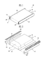
FIG. 1 is a perspective view of a pouch-type secondary battery according to an embodiment of the present invention. -
FIG. 2 is an exploded perspective view ofFIG. 1 . -
FIG. 3 is a perspective view of a battery case and an electrode assembly. -
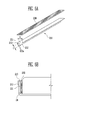
FIG. 4A is an exploded perspective view of an insulating member according to the embodiment of the present invention. -
FIG. 4B is a perspective view of the insulating member according to the embodiment of the present invention. -
FIG. 5 is an extended view of part X ofFIG. 1 . -
FIG. 6A is an exploded perspective view of an insulating member according to another embodiment of the present invention. -
FIG. 6B is a plan view of a pouch-type secondary battery according to the embodiment of the present invention. -
FIG. 7A is an exploded perspective view of an insulating member according to still another embodiment of the present invention. -
FIG. 7B is a plan view of a pouch-type secondary battery according to the embodiment of the present invention. - Referring to
Figures 1 to 3 , the pouch-typesecondary battery 100 according to this embodiment includes anelectrode assembly 30 having first and second electrode plates and a separator interposed between the electrode plates, a battery case, or pouch, 20 having anaccommodating portion 21 for accommodating theelectrode assembly 30 and asealing portion 24 provided along an edge of theaccommodating portion 21 and aninsulating member 110 provided to surround at least one part of thesealing portion 24. Theinsulating member 110 has a bonding portion, or member, 120 provided thereon. The sealingportion 24 is bent toward theaccommodating portion 21, and thebonding portion 120 is interposed between theinsulating member 110 and theaccommodating portion 21 of thebattery case 21. Theinsulating member 110 and thebonding portion 120 are integrally provided. - The pouch-type
secondary battery 100 includes theelectrode assembly 30 and thebattery case 20, and thebattery case 20 accommodates theelectrode assembly 30 and an electrolyte in theaccommodating portion 21 provided to the inside thereof. Theelectrode assembly 30 includes first andsecond electrode tabs second electrode tabs electrode assembly 30. For example, the first and second electrode plates may be positive and negative electrode plates, respectively. Thefirst electrode tab 31 may be provided to the positive electrode plate so as to act as a positive electrode tab, and thesecond electrode tab 32 may be provided to the negative electrode plate so as to act as a negative electrode tab. - Electrochemical energy is generated when ions or electrons move between the first and second electrode plates. The electrochemical energy may be provided to the outside of the
electrode assembly 30 through the first andsecond electrode tabs Lead films 33 may be provided to the first andsecond electrode tabs electrode assembly 30 may be manufactured using various methods including a method of winding or laminating the first and second electrode plates and the separator together, and the like. - The
battery case 20 may include a main body having theaccommodating portion 21 provided thereto and acover 23 connected to themain body 22 so as to cover theaccommodating portion 21. The pouch-typesecondary battery 100 may be manufactured by accommodating theelectrode assembly 30 and the electrolyte in theaccommodating portion 21 of themain body 22 and then thermally bondingedges main body 22 and thecover 23 in the state in which themain body 22 and thecover 23 are adhered closely to each other. Theaccommodating portion 21 may be provided to correspond to the shape of theelectrode assembly 30. Theaccommodating portion 21 may be provided to themain body 22 through deep drawing in which a hollow container with no joint is made using a flat plate. - The
battery case 20 may be formed with a plurality of layers including an internal resin layer A', a metal layer B and an external resin layer A. Here, the internal resin layer A', the metal layer B and the external resin layer A may be provided to be sequentially laminated. The internal resin layer A' is a part that directly faces theelectrode assembly 30, and the external resin layer A may be provided to the outermost surface of thesecondary battery 20. The internal and external resin layers A' and A are used to prevent an electrical short circuit, or the like, and may be formed using polymer resin, or the like, which is a non-conductor. On the other hand, the metal layer B is provided between the internal and external resin layers A' and A, so as to provide a predetermined mechanical strength to the battery case. For example, the metal layer B may include aluminum or the like. - When the first and
second electrode tabs battery case 20, the first andsecond electrode tabs portion 24 from being thermally bonded. Thus, thelead film 33 is settled on the sealingportion 24 of thebattery case 20, so that it is possible to prevent the sealing performance of the sealingportion 24 from being lowered. - For example, the
first electrode tab 31 may include aluminum and thesecond electrode tab 32 may include nickel. While thefirst electrode tab 31 may have the same polarity as the metal layer B of thebattery case 20, thesecond electrode tab 32 may have the opposite polarity to the metal layer B of thebattery case 20. Therefore, when thesecond electrode tab 32 comes in contact with the metal layer B exposed at an end of thebattery case 20, particularly the sealingportion 24, an electrical short circuit may occur. Further, the sealingportion 24 may increase the volume of the pouch-typesecondary battery 100, and may cause a problem in the external appearance of the pouch-typesecondary battery 100. In order to such a problem, the pouch-typesecondary battery 100 according to this embodiment may have the insulatingmember 110 provided to the sealingportion 24. - Typically, a pouch-type secondary battery is provided with a sealing portion, and the sealing portion may cause a problem of safety, such as a short circuit. In order to solve such a problem, the sealing portion is insulated. In this case, the sealing portion is insulated using a plurality of members, and a separate adhesive is used so that the sealing portion is fixed to a battery case. As such, the sealing portion is insulated through a multi-step process. This results in a complicated manufacturing process of the pouch-type secondary battery and a failure of the external appearance of the pouch-type secondary battery, and therefore, the productivity of the pouch-type secondary battery is deteriorated.
- This embodiment provides the insulating
member 110 which can allow the external appearance of the pouch-typesecondary battery 100 to be improved and improve the productivity efficiency of the pouch-typesecondary battery 100 by simplifying the manufacturing process of the pouch-typesecondary battery 100. The insulatingmember 110 is integrally provided with thebonding portion 120, and thus, the process of insulating the sealingportion 24 and the process of fixing the sealingportion 24 to thebattery case 20 are not performed as individual processes but can be collectively performed by one process. In the pouch-typesecondary battery 100, the insulatingmember 110 may guide the sealingportion 24 to be fixed at an exact position of thebattery case 20, and thus it is possible to improve the productivity and to minimize a failure rate. -
FIG. 4A is an exploded perspective view of an insulating member according to the embodiment of the present invention.FIG. 4B is a perspective view of the insulating member according to the embodiment of the present invention.FIG. 5 is an extended view of part X ofFIG. 1 . - Referring to
FIGS. 4A to 5 , the insulatingmember 110 may be provided to surround one and the other surfaces of the sealingportion 24. The insulatingmember 110 includes a buffer portion, also referred to as a joining portion, 113 provided to an inside thereof, and thebuffer portion 113 may be provided to correspond to an end of the sealingportion 24. For example, the width of thebuffer portion 113 may be provided to correspond to the thickness of the sealingportion 24. The insulatingmember 110 may be divided into first andsecond portions buffer portion 113 at the centre joining the first and second portions, which are also referred to herein as first and second wings. In this case, the first andsecond portions Folding lines 113a may be provided between thebuffer portion 113 and the first andsecond portions second portions folding lines 113a. The first andsecond portions member 110 are provided to surround the sealingportion 24, and may be provided to have a size corresponding to that of the sealingportion 24. - The sealing
portion 24 may be bent to themain body 22 so as to decrease the volume of the pouch-typesecondary battery 100. That is, the sealingportion 24 having the insulatingmember 110 may be bent to come in contact with the outside of theaccommodating portion 21 of thebattery case 20. The insulatingmember 110 is integrally provided with thebonding portion 120, and thebonding portion 120 enables the sealingportion 24 to be firmly fixed to thebattery case 20. - Hereinafter, other embodiments of the present invention will be described with reference to
FIGS. 6A to 7B . In these embodiments, components, except the following description, are similar to those in the embodiment described inFIGS. 1 to 5 , and therefore, their detailed descriptions will be omitted. -
FIG. 6A is an exploded perspective view of an insulating member according to another embodiment of the present invention.FIG. 6B is a plan view of a pouch-type secondary battery according to the embodiment of the present invention. - Referring to
FIGS. 6A and 6B , in the pouch-type secondary battery according to this embodiment, a sealingportion 24 of thebattery case 20 may be provided so that at least one part of the sealingportion 24 is surrounded by an insulatingmember 210. The insulatingmember 210 further includes abonding portion 220 integrally provided therewith. The insulatingmember 210 may be provided to surround one and the other surfaces of the sealingportion 24, and the sealingportion 24 may be bent to be fixed to thebattery case 20. Thebonding portion 220 is interposed between the insulatingmember 210 and thebattery case 20 so that the sealingportion 24 can be firmly fixed to thebattery case 20. - The insulating
member 210 may include a buffer (joining)portion 213 provided to the inside thereof and first and second portions (wings) 211 and 212 respectively extending to both sides from thebuffer portion 213. The first andsecond portions folding line 213a of thebuffer portion 213. Thefirst portion 211 of the insulatingmember 210 has thebonding portion 220 provided thereto, and thebonding portion 220 is provided between the sealingportion 24 and thebattery case 20. Thesecond portion 212 of the insulatingmember 210 may be provided to cover the outer surface of the sealingportion 24. - For example, the width of the
first portion 211 of the insulatingmember 210 having thebonding portion 220 provided in the insulatingmember 210 may be greater than that of thesecond portion 212 of the insulatingmember 210. That is, thefirst portion 211 of the insulatingmember 210 may be provided to have a size corresponding to that of the sealingportion 24, and thebonding portion 220 may be provided to have a size corresponding to that of thefirst portion 211 of the insulatingmember 210. In this case, thefirst portion 211 and thebonding portion 220 of the insulatingmember 210 are provided to have the size corresponding to that of the sealingportion 24, so as to maintain the fixing force between the sealingportion 24 and thebattery case 20. On the other hand, thesecond portion 212 of the insulatingmember 210 is provided to have a size smaller than that of the sealingportion 24, so that it is possible to reduce material cost of the pouch-type secondary battery. -
FIG. 7A is an exploded perspective view of an insulating member according to still another embodiment of the present invention.FIG. 7B is a plan view of a pouch-type secondary battery according to the embodiment of the present invention. - Referring to
FIGS. 7A and 7B , the pouch-type secondary battery may include an insulatingmember 310 and a sealingportion 24. The insulatingmember 310 may be provided to surround one and the other surfaces of the sealingportion 24, and the sealingportion 24 may be bent toward thebattery case 20 so as to be fixed to thebattery case 20. The insulatingmember 310 may further include abonding portion 320 interposed between the sealingportion 24 and thebattery case 20. - The insulating
member 310 may include a buffer (joining)portion 313 provided to the inside thereof and first and second portions (wings) 311 and 312 respectively extended to both sides from thebuffer portion 313. Folding lines 313a may be provided between thebuffer portion 313 and the first andsecond portions member 310 may further include a third portion orwing 314 extending from thebuffer portion 313. - The first and
second portions member 310 may be provided to cover the sealingportion 24, and thethird portion 314 may be extended in the opposite direction to the sealingportion 24. Thebuffer portion 313 may be provided to correspond to an end portion of the sealingportion 24. That is, the first andsecond portions member 310 fist cover the sealingportion 24, and the sealingportion 24 can be firmly fixed to thebattery case 20 by thebonding portion 320 provided on thefirst portion 311 of the insulatingmember 310. Subsequently, thethird portion 314 of the insulatingmember 310 is provided to surround thebattery case 20 once more, so that the sealingportion 24 can be more firmly fixed to thebattery case 20. - While the present invention has been described in connection with certain exemplary embodiments, it is to be understood that the invention is not limited to the disclosed embodiments, but, on the contrary, is intended to cover various modifications and equivalent arrangements included within the scope of the appended claims.
Claims (14)
- A pouch-type secondary battery comprising:an electrode assembly (30);a pouch (20) having an accommodating portion (21) for accommodating the electrode assembly and a sealing portion (24) provided along an edge of the accommodating portion; andan insulating member (110) around the sealing portion;wherein the sealing portion (24) is folded against the accommodating portion (21) and a bonding member (120) is arranged between the accommodating portion (21) and the sealing portion (24), wherein the insulating member (110) and the bonding member (120) are integrally provided.
- The pouch-type secondary battery of claim 1, wherein the insulating member (110) is folded around an edge of the sealing portion.
- The pouch-type secondary battery of claim 1 or 2, wherein the insulating member includes folding lines (113a, 213a, 313a) to allow folding of the insulating member.
- The pouch-type secondary battery of any one of the preceding claims, wherein the insulating member comprises a first wing (111) extending along a first surface of the sealing portion closest to the accommodating portion and a second wing (112) extending along a second surface of the sealing portion opposite the first surface.
- The pouch-type secondary battery of claim 4, further comprising a joining portion (113) joining the first and second wings and extending along the edge of the sealing portion.
- The pouch-type secondary battery of claim 4 or 5, wherein the first and second wings (111, 112) of the insulating member are symmetrically disposed around the edge of the sealing portion.
- The pouch-type secondary battery of claim 6, wherein the insulating member covers substantially the whole of the first and second surfaces of the sealing portion.
- The pouch-type secondary battery of claim 4 or 5, wherein the first wing (211) of the insulating member is wider than the second wing (212).
- The pouch-type secondary battery of claim 8, wherein the first wing (211) covers substantially the whole of the first surface of the sealing portion.
- The pouch-type secondary battery of any one of claims 4 to 9, wherein the insulating member further comprises a third wing (314) that is arranged to fold onto a top surface of the accommodating portion (21).
- The pouch-type secondary battery of claim 10 when dependent on claim 5, wherein the third wing extends from the joining portion in an opposite direction to the first and second wings.
- The pouch-type secondary battery of any one of the preceding claims, wherein the pouch comprises a main body and a cover for covering the accommodating portion, the main body comprising a flange at the top of the accommodating portion, wherein an edge of the cover is bonded to the flange to form the sealing portion.
- The pouch-type secondary battery of any one of the preceding claims when dependent on claim 4, wherein the bonding member (120) is arranged between the first wing and the accommodating portion.
- The pouch-type secondary battery of any one of the preceding claims when dependent on claim 4, wherein the bonding member corresponds to a side of the first wing.
Applications Claiming Priority (2)
| Application Number | Priority Date | Filing Date | Title |
|---|---|---|---|
| US201261606084P | 2012-03-02 | 2012-03-02 | |
| US13/772,151 US9017852B2 (en) | 2012-03-02 | 2013-02-20 | Secondary battery |
Publications (2)
| Publication Number | Publication Date |
|---|---|
| EP2634831A1 true EP2634831A1 (en) | 2013-09-04 |
| EP2634831B1 EP2634831B1 (en) | 2017-11-29 |
Family
ID=47750548
Family Applications (1)
| Application Number | Title | Priority Date | Filing Date |
|---|---|---|---|
| EP13157182.0A Active EP2634831B1 (en) | 2012-03-02 | 2013-02-28 | Pouch type secondary battery |
Country Status (4)
| Country | Link |
|---|---|
| US (1) | US9017852B2 (en) |
| EP (1) | EP2634831B1 (en) |
| KR (1) | KR101973056B1 (en) |
| CN (1) | CN103296231B (en) |
Cited By (1)
| Publication number | Priority date | Publication date | Assignee | Title |
|---|---|---|---|---|
| WO2020050992A1 (en) * | 2018-09-04 | 2020-03-12 | Apple Inc. | Methods and configurations for battery cell packaging |
Families Citing this family (16)
| Publication number | Priority date | Publication date | Assignee | Title |
|---|---|---|---|---|
| KR101595611B1 (en) * | 2013-03-22 | 2016-02-18 | 주식회사 엘지화학 | a secondary battery for improving energy degree |
| KR102221808B1 (en) * | 2014-08-11 | 2021-03-02 | 삼성에스디아이 주식회사 | Secondary battery |
| US20160351865A1 (en) * | 2015-05-27 | 2016-12-01 | GM Global Technology Operations LLC | Folded laminate battery cell |
| KR101766014B1 (en) * | 2015-06-17 | 2017-08-07 | 현대자동차주식회사 | Battery Cell Unit, Battery Module and System using Pouch Contact type Battery Cell |
| KR102650147B1 (en) | 2015-08-04 | 2024-03-21 | 삼성에스디아이 주식회사 | Secondary battery |
| KR101927262B1 (en) * | 2015-11-03 | 2018-12-10 | 주식회사 엘지화학 | A pouch case for a secondary battery |
| KR102395482B1 (en) * | 2016-11-07 | 2022-05-06 | 삼성에스디아이 주식회사 | Rechargeable battery |
| CN109994798B (en) * | 2017-12-26 | 2025-08-15 | Sk新能源株式会社 | Battery module and method for manufacturing same |
| KR102642969B1 (en) * | 2018-03-27 | 2024-03-04 | 에스케이온 주식회사 | Bettery cell and fabricating method of the same |
| EP4293797B1 (en) * | 2021-08-31 | 2025-10-01 | LG Energy Solution, Ltd. | Pouch-type secondary battery having excellent insulation and heat dissipation properties |
| JP2025512852A (en) * | 2022-03-31 | 2025-04-22 | エノビクス・コーポレイション | Method for forming a secondary battery assembly |
| KR102777013B1 (en) | 2022-07-05 | 2025-03-10 | 주식회사 지엔티코퍼레이션 | Roll folding and tape attach system |
| KR20240037645A (en) * | 2022-09-15 | 2024-03-22 | 에스케이온 주식회사 | Battery cell |
| KR20240109817A (en) * | 2023-01-05 | 2024-07-12 | 에스케이온 주식회사 | Folding method for battery pouch and lithium secondary battery including battery pouch |
| KR20250101294A (en) * | 2023-12-27 | 2025-07-04 | 삼성에스디아이 주식회사 | Secondary Battery |
| KR20250149486A (en) * | 2024-04-09 | 2025-10-16 | 삼성에스디아이 주식회사 | Rechargeable battery and manufacturing method thereof |
Citations (3)
| Publication number | Priority date | Publication date | Assignee | Title |
|---|---|---|---|---|
| JP2001250586A (en) * | 2000-03-03 | 2001-09-14 | Mitsubishi Chemicals Corp | Battery |
| US20050142439A1 (en) * | 2003-12-26 | 2005-06-30 | Sang-Ho Lee | Pouch type lithium secondary battery |
| JP2008041494A (en) * | 2006-08-08 | 2008-02-21 | Densei Lambda Kk | Battery cell and battery pack structure |
Family Cites Families (8)
| Publication number | Priority date | Publication date | Assignee | Title |
|---|---|---|---|---|
| JP2001250516A (en) * | 2000-03-06 | 2001-09-14 | Mitsubishi Chemicals Corp | Battery |
| JP3829630B2 (en) * | 2001-02-09 | 2006-10-04 | 三菱化学株式会社 | Secondary battery |
| KR20040107868A (en) | 2003-06-14 | 2004-12-23 | 삼성에스디아이 주식회사 | Pouched-type lithium secondary battery |
| KR100770097B1 (en) | 2006-08-07 | 2007-10-24 | 삼성에스디아이 주식회사 | Polymer battery pack |
| KR100824897B1 (en) | 2005-12-29 | 2008-04-23 | 삼성에스디아이 주식회사 | Pouch-type Battery and Formation Method |
| KR100876254B1 (en) | 2007-07-20 | 2008-12-26 | 삼성에스디아이 주식회사 | Pouch Type Secondary Battery |
| KR101002468B1 (en) | 2008-07-01 | 2010-12-17 | 삼성에스디아이 주식회사 | Pouch Type Lithium Secondary Battery |
| KR101408539B1 (en) | 2008-12-19 | 2014-06-17 | 주식회사 엘지화학 | Secondary battery pouch and pouch type secondary battery |
-
2013
- 2013-02-20 US US13/772,151 patent/US9017852B2/en active Active
- 2013-02-22 KR KR1020130019315A patent/KR101973056B1/en active Active
- 2013-02-28 EP EP13157182.0A patent/EP2634831B1/en active Active
- 2013-03-04 CN CN201310066941.0A patent/CN103296231B/en active Active
Patent Citations (3)
| Publication number | Priority date | Publication date | Assignee | Title |
|---|---|---|---|---|
| JP2001250586A (en) * | 2000-03-03 | 2001-09-14 | Mitsubishi Chemicals Corp | Battery |
| US20050142439A1 (en) * | 2003-12-26 | 2005-06-30 | Sang-Ho Lee | Pouch type lithium secondary battery |
| JP2008041494A (en) * | 2006-08-08 | 2008-02-21 | Densei Lambda Kk | Battery cell and battery pack structure |
Cited By (3)
| Publication number | Priority date | Publication date | Assignee | Title |
|---|---|---|---|---|
| WO2020050992A1 (en) * | 2018-09-04 | 2020-03-12 | Apple Inc. | Methods and configurations for battery cell packaging |
| CN112567561A (en) * | 2018-09-04 | 2021-03-26 | 苹果公司 | Method and configuration for battery cell packaging |
| US11114697B2 (en) | 2018-09-04 | 2021-09-07 | Apple Inc. | Configurations for battery cell packaging |
Also Published As
| Publication number | Publication date |
|---|---|
| CN103296231B (en) | 2017-06-20 |
| US9017852B2 (en) | 2015-04-28 |
| KR101973056B1 (en) | 2019-04-26 |
| CN103296231A (en) | 2013-09-11 |
| EP2634831B1 (en) | 2017-11-29 |
| US20130230767A1 (en) | 2013-09-05 |
| KR20130100701A (en) | 2013-09-11 |
Similar Documents
| Publication | Publication Date | Title |
|---|---|---|
| EP2634831B1 (en) | Pouch type secondary battery | |
| EP3024060B1 (en) | Electrode assembly and battery pack having the same | |
| JP6788107B2 (en) | Manufacturing method of electrode unit for battery cell and electrode unit | |
| KR100870354B1 (en) | Battery exterior material and secondary battery using same | |
| US8658308B2 (en) | Pouch-type secondary battery with insulating member and alignment mark on case | |
| CN107851852B (en) | Electricity storage device | |
| US11315744B2 (en) | Electric storage device | |
| KR20130105549A (en) | Battery cell of asymmetric structure and battery pack employed with the same | |
| JP2016502742A (en) | Electrode assembly including round corners | |
| US10177351B2 (en) | Rechargeable battery | |
| US10128470B2 (en) | Rechargeable battery | |
| US9595698B2 (en) | Battery | |
| KR101893958B1 (en) | Secondary battery | |
| KR20170047756A (en) | Rechargeable battery | |
| KR20150013014A (en) | Electrode assembly, and rechargeable battery | |
| EP2840625B1 (en) | Pouch type rechargeable battery | |
| US9236586B2 (en) | Battery pack | |
| JP2019091563A (en) | Power storage element | |
| US9240582B2 (en) | Battery pack | |
| KR101834605B1 (en) | Polymer Battery And Manufacturing Method | |
| CN106532098A (en) | Secondary battery | |
| KR20130107574A (en) | Battery cell | |
| KR20180122074A (en) | Flexible electrode assembly having strengthening structure using expanded metal on outermost electrode and inner electrode | |
| CN104037384A (en) | Rechargeable battery and pouch used for rechargeable battery |
Legal Events
| Date | Code | Title | Description |
|---|---|---|---|
| PUAI | Public reference made under article 153(3) epc to a published international application that has entered the european phase |
Free format text: ORIGINAL CODE: 0009012 |
|
| AK | Designated contracting states |
Kind code of ref document: A1 Designated state(s): AL AT BE BG CH CY CZ DE DK EE ES FI FR GB GR HR HU IE IS IT LI LT LU LV MC MK MT NL NO PL PT RO RS SE SI SK SM TR |
|
| AX | Request for extension of the european patent |
Extension state: BA ME |
|
| 17P | Request for examination filed |
Effective date: 20140304 |
|
| RBV | Designated contracting states (corrected) |
Designated state(s): AL AT BE BG CH CY CZ DE DK EE ES FI FR GB GR HR HU IE IS IT LI LT LU LV MC MK MT NL NO PL PT RO RS SE SI SK SM TR |
|
| 17Q | First examination report despatched |
Effective date: 20160125 |
|
| STAA | Information on the status of an ep patent application or granted ep patent |
Free format text: STATUS: EXAMINATION IS IN PROGRESS |
|
| GRAP | Despatch of communication of intention to grant a patent |
Free format text: ORIGINAL CODE: EPIDOSNIGR1 |
|
| STAA | Information on the status of an ep patent application or granted ep patent |
Free format text: STATUS: GRANT OF PATENT IS INTENDED |
|
| INTG | Intention to grant announced |
Effective date: 20170623 |
|
| GRAS | Grant fee paid |
Free format text: ORIGINAL CODE: EPIDOSNIGR3 |
|
| GRAA | (expected) grant |
Free format text: ORIGINAL CODE: 0009210 |
|
| STAA | Information on the status of an ep patent application or granted ep patent |
Free format text: STATUS: THE PATENT HAS BEEN GRANTED |
|
| AK | Designated contracting states |
Kind code of ref document: B1 Designated state(s): AL AT BE BG CH CY CZ DE DK EE ES FI FR GB GR HR HU IE IS IT LI LT LU LV MC MK MT NL NO PL PT RO RS SE SI SK SM TR |
|
| REG | Reference to a national code |
Ref country code: CH Ref legal event code: EP |
|
| REG | Reference to a national code |
Ref country code: AT Ref legal event code: REF Ref document number: 951151 Country of ref document: AT Kind code of ref document: T Effective date: 20171215 |
|
| REG | Reference to a national code |
Ref country code: IE Ref legal event code: FG4D |
|
| REG | Reference to a national code |
Ref country code: DE Ref legal event code: R096 Ref document number: 602013030006 Country of ref document: DE |
|
| REG | Reference to a national code |
Ref country code: FR Ref legal event code: PLFP Year of fee payment: 6 |
|
| REG | Reference to a national code |
Ref country code: NL Ref legal event code: MP Effective date: 20171129 |
|
| REG | Reference to a national code |
Ref country code: LT Ref legal event code: MG4D |
|
| REG | Reference to a national code |
Ref country code: AT Ref legal event code: MK05 Ref document number: 951151 Country of ref document: AT Kind code of ref document: T Effective date: 20171129 |
|
| PG25 | Lapsed in a contracting state [announced via postgrant information from national office to epo] |
Ref country code: LT Free format text: LAPSE BECAUSE OF FAILURE TO SUBMIT A TRANSLATION OF THE DESCRIPTION OR TO PAY THE FEE WITHIN THE PRESCRIBED TIME-LIMIT Effective date: 20171129 Ref country code: NO Free format text: LAPSE BECAUSE OF FAILURE TO SUBMIT A TRANSLATION OF THE DESCRIPTION OR TO PAY THE FEE WITHIN THE PRESCRIBED TIME-LIMIT Effective date: 20180228 Ref country code: FI Free format text: LAPSE BECAUSE OF FAILURE TO SUBMIT A TRANSLATION OF THE DESCRIPTION OR TO PAY THE FEE WITHIN THE PRESCRIBED TIME-LIMIT Effective date: 20171129 Ref country code: ES Free format text: LAPSE BECAUSE OF FAILURE TO SUBMIT A TRANSLATION OF THE DESCRIPTION OR TO PAY THE FEE WITHIN THE PRESCRIBED TIME-LIMIT Effective date: 20171129 Ref country code: SE Free format text: LAPSE BECAUSE OF FAILURE TO SUBMIT A TRANSLATION OF THE DESCRIPTION OR TO PAY THE FEE WITHIN THE PRESCRIBED TIME-LIMIT Effective date: 20171129 |
|
| PG25 | Lapsed in a contracting state [announced via postgrant information from national office to epo] |
Ref country code: BG Free format text: LAPSE BECAUSE OF FAILURE TO SUBMIT A TRANSLATION OF THE DESCRIPTION OR TO PAY THE FEE WITHIN THE PRESCRIBED TIME-LIMIT Effective date: 20180228 Ref country code: AT Free format text: LAPSE BECAUSE OF FAILURE TO SUBMIT A TRANSLATION OF THE DESCRIPTION OR TO PAY THE FEE WITHIN THE PRESCRIBED TIME-LIMIT Effective date: 20171129 Ref country code: LV Free format text: LAPSE BECAUSE OF FAILURE TO SUBMIT A TRANSLATION OF THE DESCRIPTION OR TO PAY THE FEE WITHIN THE PRESCRIBED TIME-LIMIT Effective date: 20171129 Ref country code: GR Free format text: LAPSE BECAUSE OF FAILURE TO SUBMIT A TRANSLATION OF THE DESCRIPTION OR TO PAY THE FEE WITHIN THE PRESCRIBED TIME-LIMIT Effective date: 20180301 Ref country code: HR Free format text: LAPSE BECAUSE OF FAILURE TO SUBMIT A TRANSLATION OF THE DESCRIPTION OR TO PAY THE FEE WITHIN THE PRESCRIBED TIME-LIMIT Effective date: 20171129 Ref country code: RS Free format text: LAPSE BECAUSE OF FAILURE TO SUBMIT A TRANSLATION OF THE DESCRIPTION OR TO PAY THE FEE WITHIN THE PRESCRIBED TIME-LIMIT Effective date: 20171129 |
|
| PG25 | Lapsed in a contracting state [announced via postgrant information from national office to epo] |
Ref country code: NL Free format text: LAPSE BECAUSE OF FAILURE TO SUBMIT A TRANSLATION OF THE DESCRIPTION OR TO PAY THE FEE WITHIN THE PRESCRIBED TIME-LIMIT Effective date: 20171129 |
|
| PG25 | Lapsed in a contracting state [announced via postgrant information from national office to epo] |
Ref country code: CZ Free format text: LAPSE BECAUSE OF FAILURE TO SUBMIT A TRANSLATION OF THE DESCRIPTION OR TO PAY THE FEE WITHIN THE PRESCRIBED TIME-LIMIT Effective date: 20171129 Ref country code: SK Free format text: LAPSE BECAUSE OF FAILURE TO SUBMIT A TRANSLATION OF THE DESCRIPTION OR TO PAY THE FEE WITHIN THE PRESCRIBED TIME-LIMIT Effective date: 20171129 Ref country code: EE Free format text: LAPSE BECAUSE OF FAILURE TO SUBMIT A TRANSLATION OF THE DESCRIPTION OR TO PAY THE FEE WITHIN THE PRESCRIBED TIME-LIMIT Effective date: 20171129 Ref country code: CY Free format text: LAPSE BECAUSE OF FAILURE TO SUBMIT A TRANSLATION OF THE DESCRIPTION OR TO PAY THE FEE WITHIN THE PRESCRIBED TIME-LIMIT Effective date: 20171129 Ref country code: DK Free format text: LAPSE BECAUSE OF FAILURE TO SUBMIT A TRANSLATION OF THE DESCRIPTION OR TO PAY THE FEE WITHIN THE PRESCRIBED TIME-LIMIT Effective date: 20171129 |
|
| REG | Reference to a national code |
Ref country code: DE Ref legal event code: R097 Ref document number: 602013030006 Country of ref document: DE |
|
| PG25 | Lapsed in a contracting state [announced via postgrant information from national office to epo] |
Ref country code: IT Free format text: LAPSE BECAUSE OF FAILURE TO SUBMIT A TRANSLATION OF THE DESCRIPTION OR TO PAY THE FEE WITHIN THE PRESCRIBED TIME-LIMIT Effective date: 20171129 Ref country code: PL Free format text: LAPSE BECAUSE OF FAILURE TO SUBMIT A TRANSLATION OF THE DESCRIPTION OR TO PAY THE FEE WITHIN THE PRESCRIBED TIME-LIMIT Effective date: 20171129 Ref country code: SM Free format text: LAPSE BECAUSE OF FAILURE TO SUBMIT A TRANSLATION OF THE DESCRIPTION OR TO PAY THE FEE WITHIN THE PRESCRIBED TIME-LIMIT Effective date: 20171129 Ref country code: RO Free format text: LAPSE BECAUSE OF FAILURE TO SUBMIT A TRANSLATION OF THE DESCRIPTION OR TO PAY THE FEE WITHIN THE PRESCRIBED TIME-LIMIT Effective date: 20171129 |
|
| REG | Reference to a national code |
Ref country code: CH Ref legal event code: PL |
|
| PG25 | Lapsed in a contracting state [announced via postgrant information from national office to epo] |
Ref country code: MC Free format text: LAPSE BECAUSE OF FAILURE TO SUBMIT A TRANSLATION OF THE DESCRIPTION OR TO PAY THE FEE WITHIN THE PRESCRIBED TIME-LIMIT Effective date: 20171129 |
|
| PLBE | No opposition filed within time limit |
Free format text: ORIGINAL CODE: 0009261 |
|
| STAA | Information on the status of an ep patent application or granted ep patent |
Free format text: STATUS: NO OPPOSITION FILED WITHIN TIME LIMIT |
|
| 26N | No opposition filed |
Effective date: 20180830 |
|
| REG | Reference to a national code |
Ref country code: IE Ref legal event code: MM4A |
|
| REG | Reference to a national code |
Ref country code: BE Ref legal event code: MM Effective date: 20180228 |
|
| PG25 | Lapsed in a contracting state [announced via postgrant information from national office to epo] |
Ref country code: LI Free format text: LAPSE BECAUSE OF NON-PAYMENT OF DUE FEES Effective date: 20180228 Ref country code: SI Free format text: LAPSE BECAUSE OF FAILURE TO SUBMIT A TRANSLATION OF THE DESCRIPTION OR TO PAY THE FEE WITHIN THE PRESCRIBED TIME-LIMIT Effective date: 20171129 Ref country code: LU Free format text: LAPSE BECAUSE OF NON-PAYMENT OF DUE FEES Effective date: 20180228 Ref country code: CH Free format text: LAPSE BECAUSE OF NON-PAYMENT OF DUE FEES Effective date: 20180228 |
|
| PG25 | Lapsed in a contracting state [announced via postgrant information from national office to epo] |
Ref country code: IE Free format text: LAPSE BECAUSE OF NON-PAYMENT OF DUE FEES Effective date: 20180228 |
|
| PG25 | Lapsed in a contracting state [announced via postgrant information from national office to epo] |
Ref country code: BE Free format text: LAPSE BECAUSE OF NON-PAYMENT OF DUE FEES Effective date: 20180228 |
|
| PG25 | Lapsed in a contracting state [announced via postgrant information from national office to epo] |
Ref country code: MT Free format text: LAPSE BECAUSE OF NON-PAYMENT OF DUE FEES Effective date: 20180228 |
|
| PG25 | Lapsed in a contracting state [announced via postgrant information from national office to epo] |
Ref country code: TR Free format text: LAPSE BECAUSE OF FAILURE TO SUBMIT A TRANSLATION OF THE DESCRIPTION OR TO PAY THE FEE WITHIN THE PRESCRIBED TIME-LIMIT Effective date: 20171129 |
|
| PG25 | Lapsed in a contracting state [announced via postgrant information from national office to epo] |
Ref country code: HU Free format text: LAPSE BECAUSE OF FAILURE TO SUBMIT A TRANSLATION OF THE DESCRIPTION OR TO PAY THE FEE WITHIN THE PRESCRIBED TIME-LIMIT; INVALID AB INITIO Effective date: 20130228 Ref country code: PT Free format text: LAPSE BECAUSE OF FAILURE TO SUBMIT A TRANSLATION OF THE DESCRIPTION OR TO PAY THE FEE WITHIN THE PRESCRIBED TIME-LIMIT Effective date: 20171129 |
|
| PG25 | Lapsed in a contracting state [announced via postgrant information from national office to epo] |
Ref country code: MK Free format text: LAPSE BECAUSE OF NON-PAYMENT OF DUE FEES Effective date: 20171129 |
|
| PG25 | Lapsed in a contracting state [announced via postgrant information from national office to epo] |
Ref country code: AL Free format text: LAPSE BECAUSE OF FAILURE TO SUBMIT A TRANSLATION OF THE DESCRIPTION OR TO PAY THE FEE WITHIN THE PRESCRIBED TIME-LIMIT Effective date: 20171129 Ref country code: IS Free format text: LAPSE BECAUSE OF FAILURE TO SUBMIT A TRANSLATION OF THE DESCRIPTION OR TO PAY THE FEE WITHIN THE PRESCRIBED TIME-LIMIT Effective date: 20180329 |
|
| REG | Reference to a national code |
Ref country code: DE Ref legal event code: R079 Ref document number: 602013030006 Country of ref document: DE Free format text: PREVIOUS MAIN CLASS: H01M0002020000 Ipc: H01M0050100000 |
|
| P01 | Opt-out of the competence of the unified patent court (upc) registered |
Effective date: 20230528 |
|
| PGFP | Annual fee paid to national office [announced via postgrant information from national office to epo] |
Ref country code: GB Payment date: 20260128 Year of fee payment: 14 |
|
| PGFP | Annual fee paid to national office [announced via postgrant information from national office to epo] |
Ref country code: DE Payment date: 20260128 Year of fee payment: 14 |
|
| PGFP | Annual fee paid to national office [announced via postgrant information from national office to epo] |
Ref country code: FR Payment date: 20260121 Year of fee payment: 14 |