EP2634375A2 - Seal for a turbine engine, turbine engine arrangement, and corresponding method of production - Google Patents
Seal for a turbine engine, turbine engine arrangement, and corresponding method of production Download PDFInfo
- Publication number
- EP2634375A2 EP2634375A2 EP13157045.9A EP13157045A EP2634375A2 EP 2634375 A2 EP2634375 A2 EP 2634375A2 EP 13157045 A EP13157045 A EP 13157045A EP 2634375 A2 EP2634375 A2 EP 2634375A2
- Authority
- EP
- European Patent Office
- Prior art keywords
- seal
- turbine engine
- degrees
- engine
- angled
- Prior art date
- Legal status (The legal status is an assumption and is not a legal conclusion. Google has not performed a legal analysis and makes no representation as to the accuracy of the status listed.)
- Granted
Links
- 238000000034 method Methods 0.000 title claims abstract description 8
- 241000879887 Cyrtopleura costata Species 0.000 claims description 26
- 238000005266 casting Methods 0.000 claims description 11
- PXHVJJICTQNCMI-UHFFFAOYSA-N Nickel Chemical compound [Ni] PXHVJJICTQNCMI-UHFFFAOYSA-N 0.000 claims description 6
- 239000000463 material Substances 0.000 claims description 4
- 229910052759 nickel Inorganic materials 0.000 claims description 3
- 229910000601 superalloy Inorganic materials 0.000 claims description 3
- 239000007789 gas Substances 0.000 description 8
- 230000037406 food intake Effects 0.000 description 2
- 230000001052 transient effect Effects 0.000 description 2
- 230000000712 assembly Effects 0.000 description 1
- 238000000429 assembly Methods 0.000 description 1
- 238000001816 cooling Methods 0.000 description 1
- 230000003247 decreasing effect Effects 0.000 description 1
- 230000003993 interaction Effects 0.000 description 1
- 238000003754 machining Methods 0.000 description 1
- 239000000203 mixture Substances 0.000 description 1
- 125000006850 spacer group Chemical group 0.000 description 1
Images


Classifications
-
- F—MECHANICAL ENGINEERING; LIGHTING; HEATING; WEAPONS; BLASTING
- F01—MACHINES OR ENGINES IN GENERAL; ENGINE PLANTS IN GENERAL; STEAM ENGINES
- F01D—NON-POSITIVE DISPLACEMENT MACHINES OR ENGINES, e.g. STEAM TURBINES
- F01D11/00—Preventing or minimising internal leakage of working-fluid, e.g. between stages
- F01D11/001—Preventing or minimising internal leakage of working-fluid, e.g. between stages for sealing space between stator blade and rotor
-
- F—MECHANICAL ENGINEERING; LIGHTING; HEATING; WEAPONS; BLASTING
- F01—MACHINES OR ENGINES IN GENERAL; ENGINE PLANTS IN GENERAL; STEAM ENGINES
- F01D—NON-POSITIVE DISPLACEMENT MACHINES OR ENGINES, e.g. STEAM TURBINES
- F01D11/00—Preventing or minimising internal leakage of working-fluid, e.g. between stages
- F01D11/02—Preventing or minimising internal leakage of working-fluid, e.g. between stages by non-contact sealings, e.g. of labyrinth type
-
- F—MECHANICAL ENGINEERING; LIGHTING; HEATING; WEAPONS; BLASTING
- F01—MACHINES OR ENGINES IN GENERAL; ENGINE PLANTS IN GENERAL; STEAM ENGINES
- F01D—NON-POSITIVE DISPLACEMENT MACHINES OR ENGINES, e.g. STEAM TURBINES
- F01D5/00—Blades; Blade-carrying members; Heating, heat-insulating, cooling or antivibration means on the blades or the members
- F01D5/30—Fixing blades to rotors; Blade roots ; Blade spacers
- F01D5/3007—Fixing blades to rotors; Blade roots ; Blade spacers of axial insertion type
- F01D5/3015—Fixing blades to rotors; Blade roots ; Blade spacers of axial insertion type with side plates
-
- F—MECHANICAL ENGINEERING; LIGHTING; HEATING; WEAPONS; BLASTING
- F02—COMBUSTION ENGINES; HOT-GAS OR COMBUSTION-PRODUCT ENGINE PLANTS
- F02C—GAS-TURBINE PLANTS; AIR INTAKES FOR JET-PROPULSION PLANTS; CONTROLLING FUEL SUPPLY IN AIR-BREATHING JET-PROPULSION PLANTS
- F02C7/00—Features, components parts, details or accessories, not provided for in, or of interest apart form groups F02C1/00 - F02C6/00; Air intakes for jet-propulsion plants
- F02C7/28—Arrangement of seals
-
- F—MECHANICAL ENGINEERING; LIGHTING; HEATING; WEAPONS; BLASTING
- F05—INDEXING SCHEMES RELATING TO ENGINES OR PUMPS IN VARIOUS SUBCLASSES OF CLASSES F01-F04
- F05D—INDEXING SCHEME FOR ASPECTS RELATING TO NON-POSITIVE-DISPLACEMENT MACHINES OR ENGINES, GAS-TURBINES OR JET-PROPULSION PLANTS
- F05D2250/00—Geometry
- F05D2250/30—Arrangement of components
- F05D2250/38—Arrangement of components angled, e.g. sweep angle
-
- F—MECHANICAL ENGINEERING; LIGHTING; HEATING; WEAPONS; BLASTING
- F05—INDEXING SCHEMES RELATING TO ENGINES OR PUMPS IN VARIOUS SUBCLASSES OF CLASSES F01-F04
- F05D—INDEXING SCHEME FOR ASPECTS RELATING TO NON-POSITIVE-DISPLACEMENT MACHINES OR ENGINES, GAS-TURBINES OR JET-PROPULSION PLANTS
- F05D2250/00—Geometry
- F05D2250/70—Shape
- F05D2250/71—Shape curved
- F05D2250/712—Shape curved concave
-
- F—MECHANICAL ENGINEERING; LIGHTING; HEATING; WEAPONS; BLASTING
- F05—INDEXING SCHEMES RELATING TO ENGINES OR PUMPS IN VARIOUS SUBCLASSES OF CLASSES F01-F04
- F05D—INDEXING SCHEME FOR ASPECTS RELATING TO NON-POSITIVE-DISPLACEMENT MACHINES OR ENGINES, GAS-TURBINES OR JET-PROPULSION PLANTS
- F05D2300/00—Materials; Properties thereof
- F05D2300/10—Metals, alloys or intermetallic compounds
- F05D2300/17—Alloys
- F05D2300/175—Superalloys
Definitions
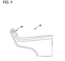
- Fig. 4 shows a perspective view of an embodiment of angel wing seal 38.
- angel wing seal 38 is formed, for example by casting, with a tuning portion 60.
- Tuning portion 60 facilitates tuning of gap 58 by providing extra material which can be removed to change the size of gap 58.
- tuning refers to changing and/or optimizing the size of gap 58. For example, during start-up and shut-down conditions of turbine 10, the temperatures of the components are constantly changing, which creates a transient condition (i.e., a continuously changing size of gap 58). However, such transient conditions are not known until testing of turbine 10.
Abstract
Description
- The present invention relates generally to rotary machines and, more particularly, to angel wing seals.
- Rotor assemblies used with turbine engines include a row of circumferentially-spaced rotor blades. Each rotor blade, sometimes referred to as a "bucket" includes an airfoil that includes a pressure side and a suction side that are connected together along leading and trailing edges. Each bucket extends radially outward from a bucket platform. Each bucket typically includes a dovetail that extends radially inward from a shank extending between the platform and the dovetail. The dovetail is used to couple the rotor blade to a rotor disk or spool.
- Wheel space cavities, defined between the rotating parts, such as the buckets, and the stationary parts of gas turbines, may be purged with cooling air to maintain the temperature of the wheel space and rotor within a desired temperature range, and to prevent hot gas path ingestion into the cavities. Seals are provided to seal the wheel space cavity. At least some known rotor blades include "angel wing seals" that extend generally axially away from the blades to form a seal by overlapping with nozzle seal lands extending from fixed components in the gas turbine. Typically, angel wing seals are cast integrally with the blade and are generally substantially planar, in cross-section, or include a preformed 90° bend at the tip that enables a portion of the angel wing to extend substantially perpendicular to the turbine engine centerline. Thus, if the angel wing seals need to be adjusted, for example to change a gap size with respect to an adjacent engine component, the gap size may be changed with respect to one direction only (i.e., axial or radial) by grinding down the angel wing seal.
- In one aspect, the invention resides in a seal for a turbine engine including a seal body disposed at a base of a turbine engine blade and a wing portion extending axially from said seal body. The wing portion has a first portion substantially parallel to a centerline of the engine and an angled upturn portion. The first portion is disposed between the seal body and the angled upturn portion. An angle between the angled upturn portion and the centerline of the engine is between 0 degrees and 90 degrees.
- In another aspect, the invention resides in a method of producing a seal for a turbine engine including forming a mold for casting the seal. The mold includes a seal body portion for forming a base of a turbine engine blade, and a wing portion for forming an angel wing extending axially from said seal body. The angel wing includes a first portion substantially parallel to a centerline of the engine and an angled upturn portion, the first portion is disposed between the seal body and the angled upturn portion. An angle between the angled upturn portion and the centerline of the engine is between 0 degrees and 90 degrees. The method also includes casting the seal using the mo ld.
- In yet another aspect, the invention resides in a turbine engine arrangement including a stationary component and a rotating component having a plurality of turbine blades. Each of the turbine blades includes a seal body disposed at a base of a turbine engine blade and a wing portion extending axially from the seal body. The wing portion has a first portion substantially parallel to a centerline of the engine and an angled upturn portion. The first portion is disposed between the seal body and the angled upturn portion. An angle between the angled upturn portion and the centerline of the engine is between 0 degrees and 90 degrees.
- Embodiments of the present invention will now be described, by way of example only, with reference to the accompanying drawings in which:
-
Fig. 1 shows a cross section of an exemplary gas turbine. -
Fig. 2 shows an enlarged perspective view of an exemplary turbine blade that may be used with the gas turbine shown inFig. 1 . -
Fig. 3 shows a cross section of the turbine blade shown inFig. 2 and taken along line 3-3. -
Fig. 1 shows illustrates a portion of anexemplary gas turbine 10 that includes arotor 11 having axially-spacedrotor wheels spacers 14 joined by a plurality of circumferentially spaced, axially extendingfasteners 16. In one embodiment,turbine 10 includes a plurality ofstages stage nozzles 18 and second-stage nozzles 20. In one embodiment, a plurality ofrotor blades stage rotor blades 22 and second-stage rotor blades 24 are circumferentially spaced aboutrotor wheels stage nozzles 18 and second-stage nozzles 20. First-stage rotor blades 22 and second-stage rotor blades 24 are rotatable with therotor wheels -
Fig. 2 illustrates an exemplary first-stage rotor blade 22 used withturbine 10. In the exemplary embodiment,rotor blade 22 includes anairfoil 26 extending from ashank 28. Shank 28 includes aplatform 30 and ashank pocket 32 havingcover plates 34. Adovetail 36 extends partially fromshank 28 to enableairfoil 26 to couple with rotor wheel 12 (shown inFig. 1 ). In the exemplary embodimentangel wing seals 38 extend outward fromrotor blade 22. Angelwing seals 38 are configured to overlap with lands 40 (shown inFig. 1 ) formed on an adjacent nozzle to form a seal. In one embodiment, theangel wing seals 38 are configured to limit ingestion of the hot gases flowing through thehot gas path 42 intowheel spaces 44. - In the exemplary embodiment,
angel wing seals 38 include anangel wing body 46 and anangled upturn portion 48 at a distal end thereof and one or morecurved root blends 50. Angelwing seals 38 include a lowerseal body surface 52 and an upperseal body surface 54. In the exemplary embodiment, lowerseal body surface 52 and upperseal body surface 54 are substantially parallel to engine centerline C. -
Fig. 3 illustrates a cross-section of a portion ofrotor blade 22. In the exemplary embodiment,angled upturn portion 48 is disposed at an angle A with respect to engine centerline C. Angle A is an angle between about 0 degrees and 90 degrees, more particularly between about 60 degrees and 70 degrees. In one embodiment, angle A is about 65 degrees. In the exemplary embodiment, at least a portion ofangel wing seal 38 overlaps a portion ofstationary part 56 and thereby forms a seal withstationary part 56 ofturbine 10. The interaction ofangel wing seal 38 withstationary part 56, which forms the seal, substantially limits hot gasses fromflow path 42 from passing through the seal. - In the exemplary embodiment, a
gap 58 having an axial component and a radial component is formed betweenstationary part 56 andangel wing seal 38. The axial direction is indicated generally as direction L and the radial direction is indicated generally as direction R. Decreasing the size ofgap 58 may increase the effectiveness of the seal. However, the size ofgap 58 may fluctuate based upon a temperature of the components inturbine 10. For example, when all of the components are cold (i.e., during engine startup conditions),gap 58 may be a first size. After all of the components have warmed up (i.e., in a steady state operating condition),gap 58 may be a second size that is smaller than the first size. Angle A and the length ofangled upturn portion 48 may be sized and configured to minimize the size ofgap 58 during steady state conditions. -
Fig. 4 shows a perspective view of an embodiment ofangel wing seal 38. In the exemplary embodiment,angel wing seal 38 is formed, for example by casting, with atuning portion 60. Tuningportion 60 facilitates tuning ofgap 58 by providing extra material which can be removed to change the size ofgap 58. As used herein, "tuning" refers to changing and/or optimizing the size ofgap 58. For example, during start-up and shut-down conditions ofturbine 10, the temperatures of the components are constantly changing, which creates a transient condition (i.e., a continuously changing size of gap 58). However, such transient conditions are not known until testing ofturbine 10. If during testing it is determined thatgap 58 is too small, in at least one of the axial and radial directions, a portion oftuning portion 60 may be removed, for example by machining, to increase the size ofgap 58. Thus, because the angled upturn portion is angled from between 0 degrees and 90 degrees, it is possible to tune the radial and axial components ofgap 58 without having to redesign, or recast,angel wing seal 38. In some embodiments, tuningportion 60 is between approximately 0.5 mm to 13 mm in length. -
Angel wing seal 38 may be formed by casting. In such embodiment, a casting mold is formed ofangel wing 38 for casting. In this embodiment, angle A may be set to maximize throughput of the casting process. In another embodiment, angle A may be set to provide a predetermined throughput (i.e., a number of castings per specified time period) of the casting process. In one embodiment,angel wing seal 38 is made of a nickel superalloy material. In another embodiment,angel wing seal 38 is integrally cast with one or more other components ofturbine 10. - This written description uses examples to disclose the invention, including the best mode, and also to enable any person skilled in the art to practice the invention, including making and using any devices or systems and performing any incorporated methods. The patentable scope of the invention is defined by the claims, and may include other examples that occur to those skilled in the art. Such other examples are intended to be within the scope of the claims if they have structural elements that do not differ from the literal language of the claims, or if they include equivalent structural elements with insubstantial differences from the literal languages of the claims.
Claims (13)
- A seal for a turbine engine (10), comprising:a seal body (38) disposed at a base of a turbine engine blade (22, 24);a wing portion (46) extending axially from said seal body, said wing portion comprising a first portion (52, 54) substantially parallel with a centerline of the engine and an angled upturn portion (48), said first portion (52, 54) extending between said seal body (38) and said angled upturn portion (48),wherein an angle (A) defined between the engine centerline (C) and said angled upturn portion (48) is between about 0 degrees and about 90 degrees.
- The seal according to Claim 1, further comprising an arcuate segment extending between said angled upturn portion (48) and said first portion (52, 54).
- The seal according to Claim 1 or 2, wherein said seal body (38) forms a shank (28) of a bucket in the turbine engine (10).
- The seal according to any of Claims 1 to 3, wherein said angled upturn portion (48) is configured to seal against a stationary component (56) of the gas turbine engine (10).
- The seal according to any of Claims 1 to 4, further comprising a tunable tip portion (60) disposed at an end of said angled upturn portion (48).
- The seal according to Claim 5, wherein said tunable tip portion (60) is configured to adjust a radial gap and an axial gap (58) of said seal with respect to a stationary component (56) in the gas turbine engine.
- The seal according to any preceding Claim, wherein said seal is configured to overlap at least a portion of a stationary component (56) in the gas turbine engine (10).
- The seal according to any preceding Claim, wherein the angled upturn portion (48) is disposed at an angle of between about 60 degrees to 70 degrees.
- The seal according to any preceding Claim, wherein said seal is fabricated from a nickel superalloy material.
- A turbine engine arrangement, comprising:a stationary component (56); anda rotating component (11) comprising a plurality of turbine blades (22, 24), each blade comprising the seal of any of claims 1 to 9.
- A method of producing a seal for a turbine engine (10), comprising:forming a mold for casting the seal, said mold comprising:a seal body portion (38) for forming a base of a turbine engine blade (22, 24);a wing portion (46) for forming an angel wing extending axially from said seal body (38), said angel wing comprising a first portion (52, 54) substantially parallel with a centerline of the engine (10) and an angled upturn portion (48), said first portion (52, 54) extending between the seal body (38) and said angled upturn portion (48);wherein an angle defined between the engine centerline and the angled upturn portion (48) is between about 0 degrees and about 90 degrees; andcasting said seal using said mold.
- The method according to Claim 11, further comprising filling said mold with a nickel superalloy material.
- The method according to Claim 11 or 12, wherein forming said mold further comprises forming a tip portion of said mold for forming a tunable tip portion (60) extending from an end of said angled upturn portion (48).
Applications Claiming Priority (1)
| Application Number | Priority Date | Filing Date | Title |
|---|---|---|---|
| US13/407,099 US9097128B2 (en) | 2012-02-28 | 2012-02-28 | Seals for rotary devices and methods of producing the same |
Publications (3)
| Publication Number | Publication Date |
|---|---|
| EP2634375A2 true EP2634375A2 (en) | 2013-09-04 |
| EP2634375A3 EP2634375A3 (en) | 2016-10-26 |
| EP2634375B1 EP2634375B1 (en) | 2019-10-23 |
Family
ID=47779904
Family Applications (1)
| Application Number | Title | Priority Date | Filing Date |
|---|---|---|---|
| EP13157045.9A Active EP2634375B1 (en) | 2012-02-28 | 2013-02-27 | Method of producing a seal between stationary and rotating components of a turbine engine |
Country Status (5)
| Country | Link |
|---|---|
| US (1) | US9097128B2 (en) |
| EP (1) | EP2634375B1 (en) |
| JP (1) | JP6259192B2 (en) |
| CN (1) | CN103291378B (en) |
| RU (1) | RU2638250C2 (en) |
Cited By (1)
| Publication number | Priority date | Publication date | Assignee | Title |
|---|---|---|---|---|
| EP3020929A1 (en) * | 2014-11-17 | 2016-05-18 | United Technologies Corporation | Airfoil platform rim seal assembly |
Families Citing this family (2)
| Publication number | Priority date | Publication date | Assignee | Title |
|---|---|---|---|---|
| US10132182B2 (en) * | 2014-11-12 | 2018-11-20 | United Technologies Corporation | Platforms with leading edge features |
| US10968762B2 (en) * | 2018-11-19 | 2021-04-06 | General Electric Company | Seal assembly for a turbo machine |
Family Cites Families (18)
| Publication number | Priority date | Publication date | Assignee | Title |
|---|---|---|---|---|
| SU1200609A1 (en) * | 1984-03-01 | 1990-10-30 | Предприятие П/Я А-1469 | Nozzle unit of gas turbine |
| JP2729531B2 (en) * | 1990-09-14 | 1998-03-18 | 株式会社日立製作所 | Gas turbine blade, method of manufacturing the same, and gas turbine |
| GB2251040B (en) | 1990-12-22 | 1994-06-22 | Rolls Royce Plc | Seal arrangement |
| JPH07259505A (en) * | 1994-03-23 | 1995-10-09 | Tohoku Electric Power Co Inc | Turbine blade and manufacture thereof |
| JPH10252412A (en) * | 1997-03-12 | 1998-09-22 | Mitsubishi Heavy Ind Ltd | Gas turbine sealing device |
| JPH10259703A (en) | 1997-03-18 | 1998-09-29 | Mitsubishi Heavy Ind Ltd | Shroud for gas turbine and platform seal system |
| DE10122732C2 (en) * | 2001-05-10 | 2003-04-30 | Mtu Aero Engines Gmbh | Arrangement for a non-hermetic seal |
| US6506016B1 (en) | 2001-11-15 | 2003-01-14 | General Electric Company | Angel wing seals for blades of a gas turbine and methods for determining angel wing seal profiles |
| US6669443B2 (en) * | 2001-11-16 | 2003-12-30 | General Electric Company | Rotor platform modification and methods using brush seals in diaphragm packing area of steam turbines to eliminate rotor bowing |
| US6779972B2 (en) | 2002-10-31 | 2004-08-24 | General Electric Company | Flowpath sealing and streamlining configuration for a turbine |
| US6905559B2 (en) * | 2002-12-06 | 2005-06-14 | General Electric Company | Nickel-base superalloy composition and its use in single-crystal articles |
| US6890150B2 (en) * | 2003-08-12 | 2005-05-10 | General Electric Company | Center-located cutter teeth on shrouded turbine blades |
| US20060275106A1 (en) * | 2005-06-07 | 2006-12-07 | Ioannis Alvanos | Blade neck fluid seal |
| US7334983B2 (en) * | 2005-10-27 | 2008-02-26 | United Technologies Corporation | Integrated bladed fluid seal |
| US7708520B2 (en) * | 2006-11-29 | 2010-05-04 | United Technologies Corporation | Gas turbine engine with concave pocket with knife edge seal |
| US8167547B2 (en) * | 2007-03-05 | 2012-05-01 | United Technologies Corporation | Gas turbine engine with canted pocket and canted knife edge seal |
| US20080263863A1 (en) * | 2007-04-27 | 2008-10-30 | United Technologies Corporation | Dimensional restoration of turbine blade knife edge seals |
| US7967559B2 (en) | 2007-05-30 | 2011-06-28 | General Electric Company | Stator-rotor assembly having surface feature for enhanced containment of gas flow and related processes |
-
2012
- 2012-02-28 US US13/407,099 patent/US9097128B2/en active Active
-
2013
- 2013-02-25 JP JP2013034220A patent/JP6259192B2/en active Active
- 2013-02-27 EP EP13157045.9A patent/EP2634375B1/en active Active
- 2013-02-27 RU RU2013108682A patent/RU2638250C2/en active
- 2013-02-28 CN CN201310063879.XA patent/CN103291378B/en active Active
Non-Patent Citations (1)
| Title |
|---|
| None |
Cited By (1)
| Publication number | Priority date | Publication date | Assignee | Title |
|---|---|---|---|---|
| EP3020929A1 (en) * | 2014-11-17 | 2016-05-18 | United Technologies Corporation | Airfoil platform rim seal assembly |
Also Published As
| Publication number | Publication date |
|---|---|
| US9097128B2 (en) | 2015-08-04 |
| CN103291378B (en) | 2017-04-26 |
| EP2634375A3 (en) | 2016-10-26 |
| RU2638250C2 (en) | 2017-12-12 |
| CN103291378A (en) | 2013-09-11 |
| US20130224026A1 (en) | 2013-08-29 |
| RU2013108682A (en) | 2014-09-10 |
| EP2634375B1 (en) | 2019-10-23 |
| JP6259192B2 (en) | 2018-01-10 |
| JP2013177892A (en) | 2013-09-09 |
Similar Documents
| Publication | Publication Date | Title |
|---|---|---|
| US8961134B2 (en) | Turbine blade or vane with separate endwall | |
| CN107035422B (en) | Turbine rotor blade with midspan shroud | |
| US9863254B2 (en) | Turbine airfoil with local wall thickness control | |
| JP2017120085A (en) | Tip shrouded turbine rotor blades | |
| US9638051B2 (en) | Turbomachine bucket having angel wing for differently sized discouragers and related methods | |
| EP3196414B1 (en) | Dual-fed airfoil tip | |
| US10066488B2 (en) | Turbomachine blade with generally radial cooling conduit to wheel space | |
| US10294805B2 (en) | Gas turbine engine integrally bladed rotor with asymmetrical trench fillets | |
| EP3184755A2 (en) | Manifold for use in a clearance control system and method of manufacturing | |
| US20160208620A1 (en) | Gas turbine engine airfoil turbulator for airfoil creep resistance | |
| EP2728120A2 (en) | Integral cover bucket assembly | |
| US10544687B2 (en) | Shrouded blade of a gas turbine engine | |
| EP2623719B1 (en) | Stress Relieving Slots for Turbine Vane Ring | |
| EP2634375B1 (en) | Method of producing a seal between stationary and rotating components of a turbine engine | |
| US10119406B2 (en) | Blade with stress-reducing bulbous projection at turn opening of coolant passages | |
| WO2013181006A1 (en) | Turbine cooling apparatus | |
| EP3693546B1 (en) | Airfoil having dead-end tip flag cavity and corresponding core assembly | |
| US10738638B2 (en) | Rotor blade with wheel space swirlers and method for forming a rotor blade with wheel space swirlers | |
| EP3159492B1 (en) | Cooling passages for gas turbine engine component |
Legal Events
| Date | Code | Title | Description |
|---|---|---|---|
| PUAI | Public reference made under article 153(3) epc to a published international application that has entered the european phase |
Free format text: ORIGINAL CODE: 0009012 |
|
| AK | Designated contracting states |
Kind code of ref document: A2 Designated state(s): AL AT BE BG CH CY CZ DE DK EE ES FI FR GB GR HR HU IE IS IT LI LT LU LV MC MK MT NL NO PL PT RO RS SE SI SK SM TR |
|
| AX | Request for extension of the european patent |
Extension state: BA ME |
|
| PUAL | Search report despatched |
Free format text: ORIGINAL CODE: 0009013 |
|
| AK | Designated contracting states |
Kind code of ref document: A3 Designated state(s): AL AT BE BG CH CY CZ DE DK EE ES FI FR GB GR HR HU IE IS IT LI LT LU LV MC MK MT NL NO PL PT RO RS SE SI SK SM TR |
|
| AX | Request for extension of the european patent |
Extension state: BA ME |
|
| RIC1 | Information provided on ipc code assigned before grant |
Ipc: F01D 11/02 20060101ALI20160920BHEP Ipc: F01D 11/00 20060101AFI20160920BHEP Ipc: F01D 5/30 20060101ALN20160920BHEP |
|
| 17P | Request for examination filed |
Effective date: 20170426 |
|
| RBV | Designated contracting states (corrected) |
Designated state(s): AL AT BE BG CH CY CZ DE DK EE ES FI FR GB GR HR HU IE IS IT LI LT LU LV MC MK MT NL NO PL PT RO RS SE SI SK SM TR |
|
| STAA | Information on the status of an ep patent application or granted ep patent |
Free format text: STATUS: REQUEST FOR EXAMINATION WAS MADE |
|
| GRAP | Despatch of communication of intention to grant a patent |
Free format text: ORIGINAL CODE: EPIDOSNIGR1 |
|
| STAA | Information on the status of an ep patent application or granted ep patent |
Free format text: STATUS: GRANT OF PATENT IS INTENDED |
|
| RIC1 | Information provided on ipc code assigned before grant |
Ipc: F01D 5/30 20060101ALN20190306BHEP Ipc: F01D 11/00 20060101AFI20190306BHEP Ipc: F01D 11/02 20060101ALI20190306BHEP |
|
| RIC1 | Information provided on ipc code assigned before grant |
Ipc: F01D 11/00 20060101AFI20190319BHEP Ipc: F01D 5/30 20060101ALN20190319BHEP Ipc: F01D 11/02 20060101ALI20190319BHEP |
|
| INTG | Intention to grant announced |
Effective date: 20190405 |
|
| GRAS | Grant fee paid |
Free format text: ORIGINAL CODE: EPIDOSNIGR3 |
|
| GRAA | (expected) grant |
Free format text: ORIGINAL CODE: 0009210 |
|
| STAA | Information on the status of an ep patent application or granted ep patent |
Free format text: STATUS: THE PATENT HAS BEEN GRANTED |
|
| AK | Designated contracting states |
Kind code of ref document: B1 Designated state(s): AL AT BE BG CH CY CZ DE DK EE ES FI FR GB GR HR HU IE IS IT LI LT LU LV MC MK MT NL NO PL PT RO RS SE SI SK SM TR |
|
| REG | Reference to a national code |
Ref country code: GB Ref legal event code: FG4D |
|
| REG | Reference to a national code |
Ref country code: CH Ref legal event code: EP |
|
| REG | Reference to a national code |
Ref country code: IE Ref legal event code: FG4D |
|
| REG | Reference to a national code |
Ref country code: DE Ref legal event code: R096 Ref document number: 602013061905 Country of ref document: DE |
|
| REG | Reference to a national code |
Ref country code: AT Ref legal event code: REF Ref document number: 1193857 Country of ref document: AT Kind code of ref document: T Effective date: 20191115 |
|
| REG | Reference to a national code |
Ref country code: NL Ref legal event code: MP Effective date: 20191023 |
|
| REG | Reference to a national code |
Ref country code: LT Ref legal event code: MG4D |
|
| PG25 | Lapsed in a contracting state [announced via postgrant information from national office to epo] |
Ref country code: ES Free format text: LAPSE BECAUSE OF FAILURE TO SUBMIT A TRANSLATION OF THE DESCRIPTION OR TO PAY THE FEE WITHIN THE PRESCRIBED TIME-LIMIT Effective date: 20191023 Ref country code: SE Free format text: LAPSE BECAUSE OF FAILURE TO SUBMIT A TRANSLATION OF THE DESCRIPTION OR TO PAY THE FEE WITHIN THE PRESCRIBED TIME-LIMIT Effective date: 20191023 Ref country code: LV Free format text: LAPSE BECAUSE OF FAILURE TO SUBMIT A TRANSLATION OF THE DESCRIPTION OR TO PAY THE FEE WITHIN THE PRESCRIBED TIME-LIMIT Effective date: 20191023 Ref country code: NO Free format text: LAPSE BECAUSE OF FAILURE TO SUBMIT A TRANSLATION OF THE DESCRIPTION OR TO PAY THE FEE WITHIN THE PRESCRIBED TIME-LIMIT Effective date: 20200123 Ref country code: PL Free format text: LAPSE BECAUSE OF FAILURE TO SUBMIT A TRANSLATION OF THE DESCRIPTION OR TO PAY THE FEE WITHIN THE PRESCRIBED TIME-LIMIT Effective date: 20191023 Ref country code: GR Free format text: LAPSE BECAUSE OF FAILURE TO SUBMIT A TRANSLATION OF THE DESCRIPTION OR TO PAY THE FEE WITHIN THE PRESCRIBED TIME-LIMIT Effective date: 20200124 Ref country code: BG Free format text: LAPSE BECAUSE OF FAILURE TO SUBMIT A TRANSLATION OF THE DESCRIPTION OR TO PAY THE FEE WITHIN THE PRESCRIBED TIME-LIMIT Effective date: 20200123 Ref country code: FI Free format text: LAPSE BECAUSE OF FAILURE TO SUBMIT A TRANSLATION OF THE DESCRIPTION OR TO PAY THE FEE WITHIN THE PRESCRIBED TIME-LIMIT Effective date: 20191023 Ref country code: PT Free format text: LAPSE BECAUSE OF FAILURE TO SUBMIT A TRANSLATION OF THE DESCRIPTION OR TO PAY THE FEE WITHIN THE PRESCRIBED TIME-LIMIT Effective date: 20200224 Ref country code: LT Free format text: LAPSE BECAUSE OF FAILURE TO SUBMIT A TRANSLATION OF THE DESCRIPTION OR TO PAY THE FEE WITHIN THE PRESCRIBED TIME-LIMIT Effective date: 20191023 Ref country code: NL Free format text: LAPSE BECAUSE OF FAILURE TO SUBMIT A TRANSLATION OF THE DESCRIPTION OR TO PAY THE FEE WITHIN THE PRESCRIBED TIME-LIMIT Effective date: 20191023 |
|
| PG25 | Lapsed in a contracting state [announced via postgrant information from national office to epo] |
Ref country code: RS Free format text: LAPSE BECAUSE OF FAILURE TO SUBMIT A TRANSLATION OF THE DESCRIPTION OR TO PAY THE FEE WITHIN THE PRESCRIBED TIME-LIMIT Effective date: 20191023 Ref country code: HR Free format text: LAPSE BECAUSE OF FAILURE TO SUBMIT A TRANSLATION OF THE DESCRIPTION OR TO PAY THE FEE WITHIN THE PRESCRIBED TIME-LIMIT Effective date: 20191023 Ref country code: IS Free format text: LAPSE BECAUSE OF FAILURE TO SUBMIT A TRANSLATION OF THE DESCRIPTION OR TO PAY THE FEE WITHIN THE PRESCRIBED TIME-LIMIT Effective date: 20200224 |
|
| PG25 | Lapsed in a contracting state [announced via postgrant information from national office to epo] |
Ref country code: AL Free format text: LAPSE BECAUSE OF FAILURE TO SUBMIT A TRANSLATION OF THE DESCRIPTION OR TO PAY THE FEE WITHIN THE PRESCRIBED TIME-LIMIT Effective date: 20191023 |
|
| REG | Reference to a national code |
Ref country code: DE Ref legal event code: R097 Ref document number: 602013061905 Country of ref document: DE |
|
| PG2D | Information on lapse in contracting state deleted |
Ref country code: IS |
|
| PG25 | Lapsed in a contracting state [announced via postgrant information from national office to epo] |
Ref country code: RO Free format text: LAPSE BECAUSE OF FAILURE TO SUBMIT A TRANSLATION OF THE DESCRIPTION OR TO PAY THE FEE WITHIN THE PRESCRIBED TIME-LIMIT Effective date: 20191023 Ref country code: DK Free format text: LAPSE BECAUSE OF FAILURE TO SUBMIT A TRANSLATION OF THE DESCRIPTION OR TO PAY THE FEE WITHIN THE PRESCRIBED TIME-LIMIT Effective date: 20191023 Ref country code: EE Free format text: LAPSE BECAUSE OF FAILURE TO SUBMIT A TRANSLATION OF THE DESCRIPTION OR TO PAY THE FEE WITHIN THE PRESCRIBED TIME-LIMIT Effective date: 20191023 Ref country code: CZ Free format text: LAPSE BECAUSE OF FAILURE TO SUBMIT A TRANSLATION OF THE DESCRIPTION OR TO PAY THE FEE WITHIN THE PRESCRIBED TIME-LIMIT Effective date: 20191023 Ref country code: IS Free format text: LAPSE BECAUSE OF FAILURE TO SUBMIT A TRANSLATION OF THE DESCRIPTION OR TO PAY THE FEE WITHIN THE PRESCRIBED TIME-LIMIT Effective date: 20200223 |
|
| REG | Reference to a national code |
Ref country code: AT Ref legal event code: MK05 Ref document number: 1193857 Country of ref document: AT Kind code of ref document: T Effective date: 20191023 |
|
| PLBE | No opposition filed within time limit |
Free format text: ORIGINAL CODE: 0009261 |
|
| STAA | Information on the status of an ep patent application or granted ep patent |
Free format text: STATUS: NO OPPOSITION FILED WITHIN TIME LIMIT |
|
| PG25 | Lapsed in a contracting state [announced via postgrant information from national office to epo] |
Ref country code: SM Free format text: LAPSE BECAUSE OF FAILURE TO SUBMIT A TRANSLATION OF THE DESCRIPTION OR TO PAY THE FEE WITHIN THE PRESCRIBED TIME-LIMIT Effective date: 20191023 Ref country code: SK Free format text: LAPSE BECAUSE OF FAILURE TO SUBMIT A TRANSLATION OF THE DESCRIPTION OR TO PAY THE FEE WITHIN THE PRESCRIBED TIME-LIMIT Effective date: 20191023 |
|
| 26N | No opposition filed |
Effective date: 20200724 |
|
| REG | Reference to a national code |
Ref country code: CH Ref legal event code: PL |
|
| GBPC | Gb: european patent ceased through non-payment of renewal fee |
Effective date: 20200227 |
|
| REG | Reference to a national code |
Ref country code: BE Ref legal event code: MM Effective date: 20200229 |
|
| PG25 | Lapsed in a contracting state [announced via postgrant information from national office to epo] |
Ref country code: MC Free format text: LAPSE BECAUSE OF FAILURE TO SUBMIT A TRANSLATION OF THE DESCRIPTION OR TO PAY THE FEE WITHIN THE PRESCRIBED TIME-LIMIT Effective date: 20191023 Ref country code: LU Free format text: LAPSE BECAUSE OF NON-PAYMENT OF DUE FEES Effective date: 20200227 |
|
| PG25 | Lapsed in a contracting state [announced via postgrant information from national office to epo] |
Ref country code: AT Free format text: LAPSE BECAUSE OF FAILURE TO SUBMIT A TRANSLATION OF THE DESCRIPTION OR TO PAY THE FEE WITHIN THE PRESCRIBED TIME-LIMIT Effective date: 20191023 Ref country code: CH Free format text: LAPSE BECAUSE OF NON-PAYMENT OF DUE FEES Effective date: 20200229 Ref country code: LI Free format text: LAPSE BECAUSE OF NON-PAYMENT OF DUE FEES Effective date: 20200229 Ref country code: SI Free format text: LAPSE BECAUSE OF FAILURE TO SUBMIT A TRANSLATION OF THE DESCRIPTION OR TO PAY THE FEE WITHIN THE PRESCRIBED TIME-LIMIT Effective date: 20191023 |
|
| PG25 | Lapsed in a contracting state [announced via postgrant information from national office to epo] |
Ref country code: FR Free format text: LAPSE BECAUSE OF NON-PAYMENT OF DUE FEES Effective date: 20200229 Ref country code: IE Free format text: LAPSE BECAUSE OF NON-PAYMENT OF DUE FEES Effective date: 20200227 Ref country code: GB Free format text: LAPSE BECAUSE OF NON-PAYMENT OF DUE FEES Effective date: 20200227 |
|
| PG25 | Lapsed in a contracting state [announced via postgrant information from national office to epo] |
Ref country code: BE Free format text: LAPSE BECAUSE OF NON-PAYMENT OF DUE FEES Effective date: 20200229 |
|
| PG25 | Lapsed in a contracting state [announced via postgrant information from national office to epo] |
Ref country code: TR Free format text: LAPSE BECAUSE OF FAILURE TO SUBMIT A TRANSLATION OF THE DESCRIPTION OR TO PAY THE FEE WITHIN THE PRESCRIBED TIME-LIMIT Effective date: 20191023 Ref country code: MT Free format text: LAPSE BECAUSE OF FAILURE TO SUBMIT A TRANSLATION OF THE DESCRIPTION OR TO PAY THE FEE WITHIN THE PRESCRIBED TIME-LIMIT Effective date: 20191023 Ref country code: CY Free format text: LAPSE BECAUSE OF FAILURE TO SUBMIT A TRANSLATION OF THE DESCRIPTION OR TO PAY THE FEE WITHIN THE PRESCRIBED TIME-LIMIT Effective date: 20191023 |
|
| PG25 | Lapsed in a contracting state [announced via postgrant information from national office to epo] |
Ref country code: MK Free format text: LAPSE BECAUSE OF FAILURE TO SUBMIT A TRANSLATION OF THE DESCRIPTION OR TO PAY THE FEE WITHIN THE PRESCRIBED TIME-LIMIT Effective date: 20191023 |
|
| PGFP | Annual fee paid to national office [announced via postgrant information from national office to epo] |
Ref country code: IT Payment date: 20230120 Year of fee payment: 11 Ref country code: DE Payment date: 20230119 Year of fee payment: 11 |
|
| P01 | Opt-out of the competence of the unified patent court (upc) registered |
Effective date: 20230522 |
|
| REG | Reference to a national code |
Ref country code: DE Ref legal event code: R082 Ref document number: 602013061905 Country of ref document: DE Ref country code: DE Ref legal event code: R081 Ref document number: 602013061905 Country of ref document: DE Owner name: GENERAL ELECTRIC TECHNOLOGY GMBH, CH Free format text: FORMER OWNER: GENERAL ELECTRIC COMPANY, SCHENECTADY, NY, US |