EP3159492B1 - Cooling passages for gas turbine engine component - Google Patents
Cooling passages for gas turbine engine component Download PDFInfo
- Publication number
- EP3159492B1 EP3159492B1 EP16191964.2A EP16191964A EP3159492B1 EP 3159492 B1 EP3159492 B1 EP 3159492B1 EP 16191964 A EP16191964 A EP 16191964A EP 3159492 B1 EP3159492 B1 EP 3159492B1
- Authority
- EP
- European Patent Office
- Prior art keywords
- outlets
- passages
- gas turbine
- turbine engine
- inlets
- Prior art date
- Legal status (The legal status is an assumption and is not a legal conclusion. Google has not performed a legal analysis and makes no representation as to the accuracy of the status listed.)
- Active
Links
- 238000001816 cooling Methods 0.000 title claims description 11
- 238000011144 upstream manufacturing Methods 0.000 claims description 16
- 239000012809 cooling fluid Substances 0.000 claims description 11
- 238000000034 method Methods 0.000 claims description 8
- 239000007789 gas Substances 0.000 description 28
- 239000000567 combustion gas Substances 0.000 description 7
- 239000000446 fuel Substances 0.000 description 5
- 230000000712 assembly Effects 0.000 description 4
- 238000000429 assembly Methods 0.000 description 4
- 239000000284 extract Substances 0.000 description 4
- 230000003068 static effect Effects 0.000 description 4
- 230000014759 maintenance of location Effects 0.000 description 3
- 230000005465 channeling Effects 0.000 description 1
- 238000004891 communication Methods 0.000 description 1
- 230000006835 compression Effects 0.000 description 1
- 238000007906 compression Methods 0.000 description 1
- 239000000463 material Substances 0.000 description 1
- 238000012986 modification Methods 0.000 description 1
- 230000004048 modification Effects 0.000 description 1
Images


Classifications
-
- F—MECHANICAL ENGINEERING; LIGHTING; HEATING; WEAPONS; BLASTING
- F01—MACHINES OR ENGINES IN GENERAL; ENGINE PLANTS IN GENERAL; STEAM ENGINES
- F01D—NON-POSITIVE DISPLACEMENT MACHINES OR ENGINES, e.g. STEAM TURBINES
- F01D5/00—Blades; Blade-carrying members; Heating, heat-insulating, cooling or antivibration means on the blades or the members
- F01D5/12—Blades
- F01D5/14—Form or construction
- F01D5/18—Hollow blades, i.e. blades with cooling or heating channels or cavities; Heating, heat-insulating or cooling means on blades
- F01D5/186—Film cooling
-
- F—MECHANICAL ENGINEERING; LIGHTING; HEATING; WEAPONS; BLASTING
- F01—MACHINES OR ENGINES IN GENERAL; ENGINE PLANTS IN GENERAL; STEAM ENGINES
- F01D—NON-POSITIVE DISPLACEMENT MACHINES OR ENGINES, e.g. STEAM TURBINES
- F01D11/00—Preventing or minimising internal leakage of working-fluid, e.g. between stages
- F01D11/08—Preventing or minimising internal leakage of working-fluid, e.g. between stages for sealing space between rotor blade tips and stator
-
- F—MECHANICAL ENGINEERING; LIGHTING; HEATING; WEAPONS; BLASTING
- F01—MACHINES OR ENGINES IN GENERAL; ENGINE PLANTS IN GENERAL; STEAM ENGINES
- F01D—NON-POSITIVE DISPLACEMENT MACHINES OR ENGINES, e.g. STEAM TURBINES
- F01D25/00—Component parts, details, or accessories, not provided for in, or of interest apart from, other groups
- F01D25/08—Cooling; Heating; Heat-insulation
- F01D25/12—Cooling
-
- F—MECHANICAL ENGINEERING; LIGHTING; HEATING; WEAPONS; BLASTING
- F01—MACHINES OR ENGINES IN GENERAL; ENGINE PLANTS IN GENERAL; STEAM ENGINES
- F01D—NON-POSITIVE DISPLACEMENT MACHINES OR ENGINES, e.g. STEAM TURBINES
- F01D9/00—Stators
- F01D9/02—Nozzles; Nozzle boxes; Stator blades; Guide conduits, e.g. individual nozzles
-
- F—MECHANICAL ENGINEERING; LIGHTING; HEATING; WEAPONS; BLASTING
- F23—COMBUSTION APPARATUS; COMBUSTION PROCESSES
- F23R—GENERATING COMBUSTION PRODUCTS OF HIGH PRESSURE OR HIGH VELOCITY, e.g. GAS-TURBINE COMBUSTION CHAMBERS
- F23R3/00—Continuous combustion chambers using liquid or gaseous fuel
- F23R3/002—Wall structures
-
- F—MECHANICAL ENGINEERING; LIGHTING; HEATING; WEAPONS; BLASTING
- F02—COMBUSTION ENGINES; HOT-GAS OR COMBUSTION-PRODUCT ENGINE PLANTS
- F02C—GAS-TURBINE PLANTS; AIR INTAKES FOR JET-PROPULSION PLANTS; CONTROLLING FUEL SUPPLY IN AIR-BREATHING JET-PROPULSION PLANTS
- F02C3/00—Gas-turbine plants characterised by the use of combustion products as the working fluid
- F02C3/04—Gas-turbine plants characterised by the use of combustion products as the working fluid having a turbine driving a compressor
-
- F—MECHANICAL ENGINEERING; LIGHTING; HEATING; WEAPONS; BLASTING
- F05—INDEXING SCHEMES RELATING TO ENGINES OR PUMPS IN VARIOUS SUBCLASSES OF CLASSES F01-F04
- F05D—INDEXING SCHEME FOR ASPECTS RELATING TO NON-POSITIVE-DISPLACEMENT MACHINES OR ENGINES, GAS-TURBINES OR JET-PROPULSION PLANTS
- F05D2220/00—Application
- F05D2220/30—Application in turbines
- F05D2220/32—Application in turbines in gas turbines
-
- F—MECHANICAL ENGINEERING; LIGHTING; HEATING; WEAPONS; BLASTING
- F05—INDEXING SCHEMES RELATING TO ENGINES OR PUMPS IN VARIOUS SUBCLASSES OF CLASSES F01-F04
- F05D—INDEXING SCHEME FOR ASPECTS RELATING TO NON-POSITIVE-DISPLACEMENT MACHINES OR ENGINES, GAS-TURBINES OR JET-PROPULSION PLANTS
- F05D2240/00—Components
- F05D2240/10—Stators
- F05D2240/11—Shroud seal segments
-
- F—MECHANICAL ENGINEERING; LIGHTING; HEATING; WEAPONS; BLASTING
- F05—INDEXING SCHEMES RELATING TO ENGINES OR PUMPS IN VARIOUS SUBCLASSES OF CLASSES F01-F04
- F05D—INDEXING SCHEME FOR ASPECTS RELATING TO NON-POSITIVE-DISPLACEMENT MACHINES OR ENGINES, GAS-TURBINES OR JET-PROPULSION PLANTS
- F05D2260/00—Function
- F05D2260/20—Heat transfer, e.g. cooling
- F05D2260/202—Heat transfer, e.g. cooling by film cooling
Definitions
- This disclosure relates to a gas turbine engine, and more particularly to a blade outer air seal (BOAS) that may be incorporated into a gas turbine engine.
- BOAS blade outer air seal
- Gas turbine engines typically include a compressor section, a combustor section, and a turbine section. During operation, air is pressurized in the compressor section and is mixed with fuel and burned in the combustor section to generate hot combustion gases. The hot combustion gases are communicated through the turbine section, which extracts energy from the hot combustion gases to power the compressor section and other loads.
- the compressor and turbine sections of a gas turbine engine include alternating rows of rotating blades and stationary vanes.
- the turbine blades rotate and extract energy from the hot combustion gases that are communicated through the gas turbine engine.
- the turbine vanes direct the hot combustion gases at a preferred angle of entry into a downstream row of blades.
- An engine case of an engine static structure may include one or more blade outer air seals (BOAS) that establish an outer radial flow path boundary for channeling the hot combustion gases.
- BOAS blade outer air seals
- BOAS are typically mounted to the engine casing with one or more retention hooks.
- a gas turbine engine having the features of the preamble of claim 1 and a method having the features of the preamble of claim 10 are disclosed in WO 94/12775 A .
- Gas turbine components with cooling hole arrangements are also disclosed in US 2013/205793 A1 and EP 1762705 A1 .
- the present invention provides a gas turbine engine as set forth in claim 1.
- the first plurality of outlets and the second plurality of outlets are positioned in an alternating pattern.
- the first plurality of outlets are located upstream of the plurality of inlets and the second plurality of outlets are located downstream of the plurality of inlets.
- the first plurality of outlets are located on a first circumferential side of the plurality of inlets.
- the second plurality of outlets are located on a second circumferential side of the plurality of inlets.
- the plurality of passages are directed in a circumferential direction.
- the plurality of passages are directed in a radial direction.
- the first plurality of outlets are located in a first linear relationship and the second plurality of outlets are located in a second linear relationship.
- the second linear relationship is parallel to the first linear relationship.
- the invention also provides a method of cooling a gas turbine engine blade outer air seal, as set forth in claim 10.
- the first linear arrangement is parallel to the second linear arrangement.
- the first plurality of outlets are located upstream of each of the inlets and the second plurality of outlets are located downstream of each of the inlets.
- FIG. 1 schematically illustrates a gas turbine engine 20.
- the exemplary gas turbine engine 20 is a two-spool turbofan engine that generally incorporates a fan section 22, a compressor section 24, a combustor section 26 and a turbine section 28.
- Alternative engines might include an augmenter section (not shown) among other systems or features.
- the fan section 22 drives air along a bypass flow path B, while the compressor section 24 drives air along a core flow path C for compression and communication into the combustor section 26.
- the hot combustion gases generated in the combustor section 26 are expanded through the turbine section 28.
- FIG. 1 schematically illustrates a gas turbine engine 20.
- the exemplary gas turbine engine 20 is a two-spool turbofan engine that generally incorporates a fan section 22, a compressor section 24, a combustor section 26 and a turbine section 28.
- Alternative engines might include an augmenter section (not shown) among other systems or features.
- the fan section 22 drives air along a bypass flow path B, while the compressor section 24 drives
- the gas turbine engine 20 generally includes a low speed spool 30 and a high speed spool 32 mounted for rotation about an engine centerline longitudinal axis A.
- the low speed spool 30 and the high speed spool 32 may be mounted relative to an engine static structure 33 via several bearing systems 31. It should be understood that other bearing systems 31 may alternatively or additionally be provided.
- the low speed spool 30 generally includes an inner shaft 34 that interconnects a fan 36, a low pressure compressor 38 and a low pressure turbine 39.
- the inner shaft 34 can be connected to the fan 36 through a geared architecture 45 to drive the fan 36 at a lower speed than the low speed spool 30.
- the high speed spool 32 includes an outer shaft 35 that interconnects a high pressure compressor 37 and a high pressure turbine 40.
- the inner shaft 34 and the outer shaft 35 are supported at various axial locations by bearing systems 31 positioned within the engine static structure 33.
- a combustor 42 is arranged between the high pressure compressor 37 and the high pressure turbine 40.
- a mid-turbine frame 44 may be arranged generally between the high pressure turbine 40 and the low pressure turbine 39.
- the mid-turbine frame 44 can support one or more bearing systems 31 of the turbine section 28.
- the mid-turbine frame 44 may include one or more airfoils 46 that extend within the core flow path C.
- the inner shaft 34 and the outer shaft 35 are concentric and rotate via the bearing systems 31 about the engine centerline longitudinal axis A, which is co-linear with their longitudinal axes.
- the core airflow is compressed by the fan 36 and/or the low pressure compressor 38 and the high pressure compressor 37, is mixed with fuel and burned in the combustor 42, and is then expanded through the high pressure turbine 40 and the low pressure turbine 39.
- the high pressure turbine 40 and the low pressure turbine 39 rotationally drive the respective high speed spool 32 and the low speed spool 30 in response to the expansion.
- the pressure ratio of the low pressure turbine 39 can be calculated by measuring the pressure prior to the inlet of the low pressure turbine 39 and relating it to the pressure measured at the outlet of the low pressure turbine 39 and prior to an exhaust nozzle of the gas turbine engine 20.
- the bypass ratio of the gas turbine engine 20 is greater than about ten
- the fan diameter is significantly larger than that of the low pressure compressor 38
- the low pressure turbine 39 has a pressure ratio that is greater than about five. It should be understood, however, that the above parameters are only exemplary of one embodiment of a geared architecture engine and that the present disclosure is applicable to other gas turbine engines, including direct drive turbofans.
- a significant amount of thrust is provided by the bypass flow path B due to the high bypass ratio.
- the fan section 22 of the gas turbine engine 20 is designed for a particular flight condition--typically cruise at about 0.8 Mach and about 35,000 feet (10,668 m). This flight condition, with the gas turbine engine 20 at its best fuel consumption, is also known as bucket cruise Thrust Specific Fuel Consumption (TSFC).
- TSFC Thrust Specific Fuel Consumption
- Fan Pressure Ratio is the pressure ratio across a blade of the fan section 22 without the use of a Fan Exit Guide Vane system.
- the low Fan Pressure Ratio according to one non-limiting embodiment of the example gas turbine engine 20 is less than 1.45.
- the Low Corrected Fan Tip Speed according to one non-limiting embodiment of the example gas turbine engine 20 is less than about 1150 fps (351 m/s).
- Each of the compressor section 24 and the turbine section 28 may include alternating rows of rotor assemblies and vane assemblies (shown schematically) that carry airfoils that extend into the core flow path C.
- the rotor assemblies can carry a plurality of rotating blades 25, while each vane assembly can carry a plurality of vanes 27 that extend into the core flow path C.
- the blades 25 create or extract energy (in the form of pressure) from the core airflow that is communicated through the gas turbine engine 20 along the core flow path C.
- the vanes 27 direct the core airflow to the blades 25 to either add or extract energy.
- Figure 2 illustrates a portion 62 of a gas turbine engine, such as the gas turbine engine 20 of Figure 1 .
- the portion 62 is representative of the high pressure turbine 40.
- other portions of the gas turbine engine 20 could benefit from the teachings of this disclosure, including but not limited to, the compressor section 24, and the low pressure turbine 39.
- a rotor disk 64 (only one shown, although multiple disks could be disposed within the portion 62) is mounted for rotation about the engine centerline longitudinal axis A relative to an engine case 66 of the engine static structure 33 (see Figure 1 ).
- the portion 62 includes alternating rows of rotating blades 68 (mounted to the rotor disk 64) and vanes (features 70A, 70B) of vane assemblies 70 that are also supported relative to the engine case 66.
- Each blade 68 of the rotor disk 64 extends to a blade tip 68T at a radially outermost portion of the blades 68.
- the blade tip 68T extends toward a blade outer air seal (BOAS) 72 (shown schematically in Figure 2 ).
- the BOAS 72 may be a segment of a BOAS assembly 74 and is secured to the engine case 66 with a retention member 73.
- a plurality of BOAS 72 may be circumferentially positioned relative to one another to provide a segmented BOAS assembly 74 that generally surrounds the rotor disk 64 and the blades 68 carried by the rotor disk 64.
- a cooling fluid F that is separate from the core flow path C may be communicated into a space at least partially defined by the BOAS 72 to provide a dedicated source of cooling fluid for cooling the BOAS 72 and other nearby hardware.
- the cooling fluid F is airflow sourced from the high pressure compressor 37 or any other upstream portion of the gas turbine engine 20.
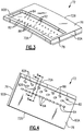
- Figures 3 and 4 illustrate the BOAS 72 without a retention member 73 for securing the BOAS 72 to the engine case 66.
- the BOAS 72 includes a radially outer side 76 and a radially inner side 78. In this disclosure, radial or radially is in relation to the engine axis A unless stated otherwise.
- the BOAS 72 includes an axially upstream side 72A and an axially downstream side 72B. In this disclosure, axial or axially is in relation to the engine axis A unless stated otherwise.
- the radially outer side 76 includes an impingement cavity 80 for directing the cooling fluid F through a first plurality of passages 82 and a second plurality of passage 84 in the BOAS 72.
- the first plurality of passages 82 are axially upstream from the second plurality of passages 84.
- the second plurality of passages 84 could be located upstream of the first plurality of passages 82.
- the first plurality of passages 82 each include an inlet 86 on the radially outer side 76 and an outlet 88 on the radially inner side 78.
- the first plurality of passages 82 include a cylindrical cross section and the inlet 86 and the outlet 88 each have an elliptical shape due to the non-perpendicular angle formed between an axis extending longitudinally through a center of each of the first plurality of passages 82 and the radially outer and inner sides 76, 78.
- Each of the first plurality of passages 82 include a directional component that extends in a circumferential direction either toward or away from opposing first and second circumferential ends 90A, 90B of the BOAS 72.
- the first plurality of passages 82 extends in a direction from the first circumferential end 90A toward the second circumferential end 90B.
- each of the first plurality of passages 82 would extend in a radial direction and would be transverse to the engine axis A.
- the first plurality of passages 82 also includes alternating forward and aft passages 82A, 82B that include an upstream or a downstream directional component in addition to the circumferential component discussed above.
- alternating forward and aft passages 82A, 82B that include an upstream or a downstream directional component in addition to the circumferential component discussed above.
- the second plurality of passages 84 includes an inlet 92 and an outlet 94.
- the second plurality of cooling passages 84 include a cylindrical cross section with the inlet 92 and the outlet 94 having an elliptical shape due to the non-perpendicular angle formed between an axis extending longitudinally through a center of each of the first plurality of passages 82 and the radially outer and inner sides 76, 78.
- Each of the second plurality of passages 84 include a directional component that extends in a circumferential direction toward or away from either the opposing first and second circumferential ends 90A, 90B of the BOAS 72.
- the second plurality of passages 84 extend in a direction from the first circumferential end 90A to the second circumferential end 90B similar to the first plurality of passages 82.
- Figures 5 and 6 illustrate segments views of the radially inner and outer sides 78, 76 of the BOAS 72 surrounding the first plurality of passages 82.
- the inlets 86 to the first plurality of passages 82 have a constant axial position relative to the engine axis A and the outlets 88 include alternating forward and aft passages 82A, 82B that are spaced axially from each other.
- the inlets 86 and the outlets 88 to the forward and aft passages 82A, 82B are arranged linearly with a constant axial position.
- the inlets 86 and the outlets 88 could also be arranged linearly in an axial direction or a direction transverse across the BOAS 72 such that the forward and aft passages 82A, 82B are spaced from each other while still being parallel to each other.
- the forward and aft passages 82A, 82B could be linearly arranged and be parallel to the linear arrangement of the inlets 86.
- the inlets 86 and the outlets 88 could be arranged in a non-linear arrangement.
- the aft passage 82B includes the directional component that extends radially inward and downstream from the upstream side 72A towards the downstream side 72B in additional to having a circumferentially directed component.
- the aft passage 82B includes a cylindrical cross section that increases from the radially outer side 76 toward the radially inner side 78.
- the forward passage 82A includes the component that extends radially inward and upstream from the downstream side 72B towards the upstream side 72A.
- the forward passage 82A includes a cylindrical cross section that increases from the radially outer side 76 to the radially inner side 78.
Description
- This disclosure relates to a gas turbine engine, and more particularly to a blade outer air seal (BOAS) that may be incorporated into a gas turbine engine.
- Gas turbine engines typically include a compressor section, a combustor section, and a turbine section. During operation, air is pressurized in the compressor section and is mixed with fuel and burned in the combustor section to generate hot combustion gases. The hot combustion gases are communicated through the turbine section, which extracts energy from the hot combustion gases to power the compressor section and other loads.
- The compressor and turbine sections of a gas turbine engine include alternating rows of rotating blades and stationary vanes. The turbine blades rotate and extract energy from the hot combustion gases that are communicated through the gas turbine engine. The turbine vanes direct the hot combustion gases at a preferred angle of entry into a downstream row of blades.
- An engine case of an engine static structure may include one or more blade outer air seals (BOAS) that establish an outer radial flow path boundary for channeling the hot combustion gases. BOAS are typically mounted to the engine casing with one or more retention hooks.
- A gas turbine engine having the features of the preamble of
claim 1 and a method having the features of the preamble of claim 10 are disclosed inWO 94/12775 A US 2013/205793 A1 andEP 1762705 A1 . - From a first aspect, the present invention provides a gas turbine engine as set forth in
claim 1. - In an embodiment of the above, the first plurality of outlets and the second plurality of outlets are positioned in an alternating pattern.
- In a further embodiment of any of the above, the first plurality of outlets are located upstream of the plurality of inlets and the second plurality of outlets are located downstream of the plurality of inlets.
- In a further embodiment of any of the above, the first plurality of outlets are located on a first circumferential side of the plurality of inlets. The second plurality of outlets are located on a second circumferential side of the plurality of inlets.
- In a further embodiment of any of the above, the plurality of passages are directed in a circumferential direction.
- In a further embodiment of any of the above, the plurality of passages are directed in a radial direction.
- In a further embodiment of any of the above, the first plurality of outlets are located in a first linear relationship and the second plurality of outlets are located in a second linear relationship.
- In a further embodiment of any of the above, the second linear relationship is parallel to the first linear relationship.
- The invention also provides a method of cooling a gas turbine engine blade outer air seal, as set forth in claim 10.
- In an embodiment of the above method, the first linear arrangement is parallel to the second linear arrangement.
- In a further embodiment of any of the above methods, the first plurality of outlets are located upstream of each of the inlets and the second plurality of outlets are located downstream of each of the inlets.
-
-
Figure 1 is a schematic view of an example gas turbine engine. -
Figure 2 illustrates a cross-sectional view of a portion of the gas turbine engine. -
Figure 3 illustrates a perspective view of a portion of a blade outer air seal. -
Figure 4 illustrates another perspective view of the portion of the blade outer air seal fromFigure 3 . -
Figure 5 illustrates an arrangement of inlets. -
Figure 6 illustrates an arrangement of outlets. -
Figure 7 illustrates a cross-sectional view taken along line 7-7 ofFigure 4 . -
Figure 8 illustrates a cross sectional view taken along line 8-8 ofFigure 4 . -
Figure 1 schematically illustrates agas turbine engine 20. The exemplarygas turbine engine 20 is a two-spool turbofan engine that generally incorporates afan section 22, acompressor section 24, acombustor section 26 and aturbine section 28. Alternative engines might include an augmenter section (not shown) among other systems or features. Thefan section 22 drives air along a bypass flow path B, while thecompressor section 24 drives air along a core flow path C for compression and communication into thecombustor section 26. The hot combustion gases generated in thecombustor section 26 are expanded through theturbine section 28. Although depicted as a turbofan gas turbine engine in this non-limiting embodiment, it should be understood that the concepts described herein are not limited to turbofan engines and these teachings could extend to other types of engines, including but not limited to, three-spool engine architectures. - The
gas turbine engine 20 generally includes alow speed spool 30 and ahigh speed spool 32 mounted for rotation about an engine centerline longitudinal axis A. Thelow speed spool 30 and thehigh speed spool 32 may be mounted relative to an enginestatic structure 33 viaseveral bearing systems 31. It should be understood thatother bearing systems 31 may alternatively or additionally be provided. - The
low speed spool 30 generally includes aninner shaft 34 that interconnects afan 36, alow pressure compressor 38 and alow pressure turbine 39. Theinner shaft 34 can be connected to thefan 36 through a gearedarchitecture 45 to drive thefan 36 at a lower speed than thelow speed spool 30. Thehigh speed spool 32 includes anouter shaft 35 that interconnects ahigh pressure compressor 37 and ahigh pressure turbine 40. In this embodiment, theinner shaft 34 and theouter shaft 35 are supported at various axial locations bybearing systems 31 positioned within the enginestatic structure 33. - A
combustor 42 is arranged between thehigh pressure compressor 37 and thehigh pressure turbine 40. Amid-turbine frame 44 may be arranged generally between thehigh pressure turbine 40 and thelow pressure turbine 39. Themid-turbine frame 44 can support one or more bearingsystems 31 of theturbine section 28. Themid-turbine frame 44 may include one ormore airfoils 46 that extend within the core flow path C. - The
inner shaft 34 and theouter shaft 35 are concentric and rotate via thebearing systems 31 about the engine centerline longitudinal axis A, which is co-linear with their longitudinal axes. The core airflow is compressed by thefan 36 and/or thelow pressure compressor 38 and thehigh pressure compressor 37, is mixed with fuel and burned in thecombustor 42, and is then expanded through thehigh pressure turbine 40 and thelow pressure turbine 39. Thehigh pressure turbine 40 and thelow pressure turbine 39 rotationally drive the respectivehigh speed spool 32 and thelow speed spool 30 in response to the expansion. - The pressure ratio of the
low pressure turbine 39 can be calculated by measuring the pressure prior to the inlet of thelow pressure turbine 39 and relating it to the pressure measured at the outlet of thelow pressure turbine 39 and prior to an exhaust nozzle of thegas turbine engine 20. In one non-limiting embodiment, the bypass ratio of thegas turbine engine 20 is greater than about ten, the fan diameter is significantly larger than that of thelow pressure compressor 38, and thelow pressure turbine 39 has a pressure ratio that is greater than about five. It should be understood, however, that the above parameters are only exemplary of one embodiment of a geared architecture engine and that the present disclosure is applicable to other gas turbine engines, including direct drive turbofans. - In one embodiment of the exemplary
gas turbine engine 20, a significant amount of thrust is provided by the bypass flow path B due to the high bypass ratio. Thefan section 22 of thegas turbine engine 20 is designed for a particular flight condition--typically cruise at about 0.8 Mach and about 35,000 feet (10,668 m). This flight condition, with thegas turbine engine 20 at its best fuel consumption, is also known as bucket cruise Thrust Specific Fuel Consumption (TSFC). TSFC is an industry standard parameter of fuel consumption per unit of thrust. - Fan Pressure Ratio is the pressure ratio across a blade of the
fan section 22 without the use of a Fan Exit Guide Vane system. The low Fan Pressure Ratio according to one non-limiting embodiment of the examplegas turbine engine 20 is less than 1.45. Low Corrected Fan Tip Speed is the actual fan tip speed divided by an industry standard temperature correction of [(Tram°R)/(518.7°R)]^0.5 (where °R = K x 9/5). The Low Corrected Fan Tip Speed according to one non-limiting embodiment of the examplegas turbine engine 20 is less than about 1150 fps (351 m/s). - Each of the
compressor section 24 and theturbine section 28 may include alternating rows of rotor assemblies and vane assemblies (shown schematically) that carry airfoils that extend into the core flow path C. For example, the rotor assemblies can carry a plurality ofrotating blades 25, while each vane assembly can carry a plurality ofvanes 27 that extend into the core flow path C. Theblades 25 create or extract energy (in the form of pressure) from the core airflow that is communicated through thegas turbine engine 20 along the core flow path C. Thevanes 27 direct the core airflow to theblades 25 to either add or extract energy. -
Figure 2 illustrates aportion 62 of a gas turbine engine, such as thegas turbine engine 20 ofFigure 1 . In the illustrated embodiment, theportion 62 is representative of thehigh pressure turbine 40. However, it should be appreciated that other portions of thegas turbine engine 20 could benefit from the teachings of this disclosure, including but not limited to, thecompressor section 24, and thelow pressure turbine 39. - In one exemplary embodiment, a rotor disk 64 (only one shown, although multiple disks could be disposed within the portion 62) is mounted for rotation about the engine centerline longitudinal axis A relative to an
engine case 66 of the engine static structure 33 (seeFigure 1 ). Theportion 62 includes alternating rows of rotating blades 68 (mounted to the rotor disk 64) and vanes (features 70A, 70B) ofvane assemblies 70 that are also supported relative to theengine case 66. - Each
blade 68 of therotor disk 64 extends to ablade tip 68T at a radially outermost portion of theblades 68. Theblade tip 68T extends toward a blade outer air seal (BOAS) 72 (shown schematically inFigure 2 ). TheBOAS 72 may be a segment of aBOAS assembly 74 and is secured to theengine case 66 with aretention member 73. For example, a plurality ofBOAS 72 may be circumferentially positioned relative to one another to provide a segmentedBOAS assembly 74 that generally surrounds therotor disk 64 and theblades 68 carried by therotor disk 64. - A cooling fluid F that is separate from the core flow path C may be communicated into a space at least partially defined by the
BOAS 72 to provide a dedicated source of cooling fluid for cooling theBOAS 72 and other nearby hardware. In one embodiment, the cooling fluid F is airflow sourced from thehigh pressure compressor 37 or any other upstream portion of thegas turbine engine 20. -
Figures 3 and 4 illustrate theBOAS 72 without aretention member 73 for securing theBOAS 72 to theengine case 66. TheBOAS 72 includes a radiallyouter side 76 and a radiallyinner side 78. In this disclosure, radial or radially is in relation to the engine axis A unless stated otherwise. TheBOAS 72 includes an axiallyupstream side 72A and an axiallydownstream side 72B. In this disclosure, axial or axially is in relation to the engine axis A unless stated otherwise. - The radially
outer side 76 includes animpingement cavity 80 for directing the cooling fluid F through a first plurality ofpassages 82 and a second plurality ofpassage 84 in theBOAS 72. In the illustrated embodiment, the first plurality ofpassages 82 are axially upstream from the second plurality ofpassages 84. In another example embodiment, the second plurality ofpassages 84 could be located upstream of the first plurality ofpassages 82. - The first plurality of
passages 82 each include aninlet 86 on the radiallyouter side 76 and anoutlet 88 on the radiallyinner side 78. The first plurality ofpassages 82 include a cylindrical cross section and theinlet 86 and theoutlet 88 each have an elliptical shape due to the non-perpendicular angle formed between an axis extending longitudinally through a center of each of the first plurality ofpassages 82 and the radially outer andinner sides - Each of the first plurality of
passages 82 include a directional component that extends in a circumferential direction either toward or away from opposing first and second circumferential ends 90A, 90B of theBOAS 72. In the illustrated embodiment, the first plurality ofpassages 82 extends in a direction from the firstcircumferential end 90A toward the secondcircumferential end 90B. When applied to an airfoil, such as a blade or vane, each of the first plurality ofpassages 82 would extend in a radial direction and would be transverse to the engine axis A. - The first plurality of
passages 82 also includes alternating forward andaft passages forward passage 82A and theaft passage 82B in an alternating arrangement, a spacing between theadjacent outlets 88 is increased. By increasing the spacing between theadjacent outlets 88, the structural rigidity of theBOAS 72 is increased by reducing the concentration of material removed from theBOAS 72. - The second plurality of
passages 84 includes aninlet 92 and anoutlet 94. The second plurality ofcooling passages 84 include a cylindrical cross section with theinlet 92 and theoutlet 94 having an elliptical shape due to the non-perpendicular angle formed between an axis extending longitudinally through a center of each of the first plurality ofpassages 82 and the radially outer andinner sides - Each of the second plurality of
passages 84 include a directional component that extends in a circumferential direction toward or away from either the opposing first and second circumferential ends 90A, 90B of theBOAS 72. In the illustrated embodiment, the second plurality ofpassages 84 extend in a direction from the firstcircumferential end 90A to the secondcircumferential end 90B similar to the first plurality ofpassages 82. -
Figures 5 and 6 illustrate segments views of the radially inner andouter sides BOAS 72 surrounding the first plurality ofpassages 82. As shown inFigures 5 and 6 , theinlets 86 to the first plurality ofpassages 82 have a constant axial position relative to the engine axis A and theoutlets 88 include alternating forward andaft passages - In the illustrated embodiment, the
inlets 86 and theoutlets 88 to the forward andaft passages inlets 86 and theoutlets 88 could also be arranged linearly in an axial direction or a direction transverse across theBOAS 72 such that the forward andaft passages aft passages inlets 86. Alternatively, theinlets 86 and theoutlets 88 could be arranged in a non-linear arrangement. - As shown in
Figure 7 , theaft passage 82B includes the directional component that extends radially inward and downstream from theupstream side 72A towards thedownstream side 72B in additional to having a circumferentially directed component. Theaft passage 82B includes a cylindrical cross section that increases from the radiallyouter side 76 toward the radiallyinner side 78. By directing the cooling fluid F passing through theaft passages 82B in the circumferential and aft direction, the cooling fluid F passing through theaft passage 82B will provide film cooling for the radiallyinner surface 78 of theBOAS 72. - As shown in
Figure 8 , theforward passage 82A includes the component that extends radially inward and upstream from thedownstream side 72B towards theupstream side 72A. Theforward passage 82A includes a cylindrical cross section that increases from the radiallyouter side 76 to the radiallyinner side 78. By directing the cooling fluid F passing through theforward passage 82A in the circumferential and forward direction, the cooling fluid F passing through theforward passage 82A will provide film cooling for the radiallyinner side 78 of theBOAS 72. - The preceding description is exemplary rather than limiting in nature. Variations and modifications to the disclosed examples may become apparent to those skilled in the art that do not necessarily depart from the essence of this disclosure. The scope of legal protection given to this disclosure can only be determined by studying the following claims.
Claims (12)
- A gas turbine engine (20) comprising:at least one blade outer air seal (72) including a wall portion having a first side (76) and a second side (78); anda plurality of cooling passages (82) extending between the first side (76) of the wall portion and the second side (78) of the wall portion comprising:a plurality of inlets (86) located on the first side (76) of the wall portion at a first axial position, the plurality of inlets (86) having a constant axial position relative to an axis (A) of the engine (20); anda plurality of outlets (88) located on a second side (78) of the wall portion, wherein the plurality of outlets (88) include a first plurality of outlets (88) located axially upstream from a second plurality of outlets (88),characterised in that:the plurality of passages (82) comprises alternating forward passages including an axially upstream directional component in addition to a circumferential component(82A) and aft passages (82B) including an axially downstream directional component in addition to a circumferential component; and the plurality of inlets (86) are connected to corresponding ones of the first plurality of outlets (88) by the forward passages (82A) and to corresponding ones of the second plurality of outlets (88) by the aft passages (82B).
- The gas turbine engine (20) of claim 1, wherein the first plurality of outlets and the second plurality of outlets are positioned in an alternating pattern.
- The gas turbine engine (20) of claim 1 or 2, wherein the first plurality of outlets (88) are located upstream of the plurality of inlets (86) and the second plurality of outlets (88) are located downstream of the plurality of inlets (86).
- The gas turbine engine (20) of any preceding claim, wherein the plurality of passages (82) are directed in a circumferential direction.
- The gas turbine engine (20) of any of claims 1 to 4, wherein the plurality of passages (82) are directed in a radial direction.
- The gas turbine engine (20) of any preceding claim, wherein the plurality of inlets (86) and the plurality of outlets (88) are elliptical.
- The gas turbine engine (20) of any preceding claim, wherein a diameter of at least one of the plurality of passages (82) increases from the first side (76) of the wall portion to the second side (78) of the wall portion.
- The gas turbine engine (20) of any preceding claim, wherein the first plurality of outlets (88) are located in a first linear relationship and the second plurality of outlets (88) are located in a second linear relationship.
- The gas turbine engine (20) of claim 8, wherein the second linear relationship is parallel to the first linear relationship.
- A method of cooling a gas turbine engine blade outer air seal comprising:directing a cooling fluid into a first plurality of linearly arranged inlets (86) located on a first side (76) of a wall portion of the blade outer air seal at a first axial position,characterised in that:the method further comprises directing the cooling fluid through a corresponding one of a plurality of alternating forward passages including an axially upstream directional component in addition to a circumferential component and aft passages (82A, 82B)including an axially downstream directional component in addition to a circumferential component, wherein the first plurality of linearly arranged inlets (86) have a constant axial position relative to an axis (A) of the engine (20); andfilm cooling a second side (78) of the blade outer air seal with cooling fluid exiting the plurality of forward passages (82A) through a first plurality of outlets (88) having a first linear arrangement and with cooling air exiting the plurality of aft passages (82B) through a second plurality of outlets (88) having a second linear arrangement spaced from the first linear arrangement, the first plurality of outlets (88) located axially upstream from the second plurality of outlets (88).
- The method of claim 10, wherein the first linear arrangement is parallel to the second linear arrangement.
- The method of claim 10 or 11, wherein the first plurality of outlets (88) are located upstream of each of the inlets (86) and the second plurality of outlets (88) are located downstream of each of the inlets (86).
Applications Claiming Priority (1)
| Application Number | Priority Date | Filing Date | Title |
|---|---|---|---|
| US14/870,175 US10526897B2 (en) | 2015-09-30 | 2015-09-30 | Cooling passages for gas turbine engine component |
Publications (2)
| Publication Number | Publication Date |
|---|---|
| EP3159492A1 EP3159492A1 (en) | 2017-04-26 |
| EP3159492B1 true EP3159492B1 (en) | 2020-03-11 |
Family
ID=57137832
Family Applications (1)
| Application Number | Title | Priority Date | Filing Date |
|---|---|---|---|
| EP16191964.2A Active EP3159492B1 (en) | 2015-09-30 | 2016-09-30 | Cooling passages for gas turbine engine component |
Country Status (2)
| Country | Link |
|---|---|
| US (1) | US10526897B2 (en) |
| EP (1) | EP3159492B1 (en) |
Family Cites Families (11)
| Publication number | Priority date | Publication date | Assignee | Title |
|---|---|---|---|---|
| US5181379A (en) | 1990-11-15 | 1993-01-26 | General Electric Company | Gas turbine engine multi-hole film cooled combustor liner and method of manufacture |
| WO1994012775A1 (en) | 1992-11-24 | 1994-06-09 | United Technologies Corporation | Coolable outer air seal assembly for a turbine |
| US5649806A (en) | 1993-11-22 | 1997-07-22 | United Technologies Corporation | Enhanced film cooling slot for turbine blade outer air seals |
| US6243948B1 (en) | 1999-11-18 | 2001-06-12 | General Electric Company | Modification and repair of film cooling holes in gas turbine engine components |
| US7296967B2 (en) * | 2005-09-13 | 2007-11-20 | General Electric Company | Counterflow film cooled wall |
| US8439629B2 (en) | 2007-03-01 | 2013-05-14 | United Technologies Corporation | Blade outer air seal |
| US7704039B1 (en) | 2007-03-21 | 2010-04-27 | Florida Turbine Technologies, Inc. | BOAS with multiple trenched film cooling slots |
| US8740551B2 (en) | 2009-08-18 | 2014-06-03 | Pratt & Whitney Canada Corp. | Blade outer air seal cooling |
| US8596962B1 (en) | 2011-03-21 | 2013-12-03 | Florida Turbine Technologies, Inc. | BOAS segment for a turbine |
| US8596963B1 (en) | 2011-07-07 | 2013-12-03 | Florida Turbine Technologies, Inc. | BOAS for a turbine |
| US8572983B2 (en) | 2012-02-15 | 2013-11-05 | United Technologies Corporation | Gas turbine engine component with impingement and diffusive cooling |
-
2015
- 2015-09-30 US US14/870,175 patent/US10526897B2/en active Active
-
2016
- 2016-09-30 EP EP16191964.2A patent/EP3159492B1/en active Active
Non-Patent Citations (1)
| Title |
|---|
| None * |
Also Published As
| Publication number | Publication date |
|---|---|
| US10526897B2 (en) | 2020-01-07 |
| US20170089204A1 (en) | 2017-03-30 |
| EP3159492A1 (en) | 2017-04-26 |
Similar Documents
| Publication | Publication Date | Title |
|---|---|---|
| EP2964934B1 (en) | Gas turbine engine component having variable width feather seal slot | |
| EP3029278B1 (en) | Blade outer air seal support structure | |
| EP3052762B1 (en) | Feature to provide cooling flow to a turbine rotor disk | |
| EP2948636B1 (en) | Gas turbine engine component having contoured rib end | |
| EP2943653B1 (en) | Rotor blade and corresponding gas turbine engine | |
| EP2877709B1 (en) | Blade outer air seal for a gas turbine engine | |
| EP3009616B1 (en) | Gas turbine component with platform cooling | |
| US20140093361A1 (en) | Airfoil with variable trip strip height | |
| US10641103B2 (en) | Trailing edge configuration with cast slots and drilled filmholes | |
| EP2885520B1 (en) | Component for a gas turbine engine and corresponding method of cooling | |
| EP3047111B1 (en) | Component for a gas turbine engine, corresponding gas turbine engine and method of cooling | |
| EP3008309B1 (en) | Gas turbine engine flow control device | |
| EP2961940B1 (en) | Contoured blade outer air seal for a gas turbine engine | |
| EP2927429B1 (en) | Gas turbine engine component with flow separating rib | |
| EP3047107B1 (en) | Gas turbine engine component platform seal cooling | |
| US20160003152A1 (en) | Gas turbine engine multi-vaned stator cooling configuration | |
| US20150369071A1 (en) | Gas turbine engine component having tip vortex creation feature | |
| EP2995778B1 (en) | Method and assembly for reducing secondary heat in a gas turbine engine | |
| EP3159492B1 (en) | Cooling passages for gas turbine engine component | |
| EP3181828B1 (en) | Blade outer air seal with integrated air shield | |
| EP3049640B1 (en) | Boas thermal protection | |
| EP2986823B1 (en) | Airfoil component | |
| EP3091199A1 (en) | Airfoil and corresponding vane | |
| EP3550105B1 (en) | Gas turbine engine rotor disk |
Legal Events
| Date | Code | Title | Description |
|---|---|---|---|
| PUAI | Public reference made under article 153(3) epc to a published international application that has entered the european phase |
Free format text: ORIGINAL CODE: 0009012 |
|
| STAA | Information on the status of an ep patent application or granted ep patent |
Free format text: STATUS: THE APPLICATION HAS BEEN PUBLISHED |
|
| AK | Designated contracting states |
Kind code of ref document: A1 Designated state(s): AL AT BE BG CH CY CZ DE DK EE ES FI FR GB GR HR HU IE IS IT LI LT LU LV MC MK MT NL NO PL PT RO RS SE SI SK SM TR |
|
| AX | Request for extension of the european patent |
Extension state: BA ME |
|
| RIN1 | Information on inventor provided before grant (corrected) |
Inventor name: SWIFT, ANTHONY B. Inventor name: LUTJEN, PAUL M. |
|
| RIN1 | Information on inventor provided before grant (corrected) |
Inventor name: LUTJEN, PAUL M. Inventor name: SWIFT, ANTHONY B. |
|
| STAA | Information on the status of an ep patent application or granted ep patent |
Free format text: STATUS: REQUEST FOR EXAMINATION WAS MADE |
|
| 17P | Request for examination filed |
Effective date: 20171026 |
|
| RBV | Designated contracting states (corrected) |
Designated state(s): AL AT BE BG CH CY CZ DE DK EE ES FI FR GB GR HR HU IE IS IT LI LT LU LV MC MK MT NL NO PL PT RO RS SE SI SK SM TR |
|
| STAA | Information on the status of an ep patent application or granted ep patent |
Free format text: STATUS: EXAMINATION IS IN PROGRESS |
|
| 17Q | First examination report despatched |
Effective date: 20180619 |
|
| GRAP | Despatch of communication of intention to grant a patent |
Free format text: ORIGINAL CODE: EPIDOSNIGR1 |
|
| STAA | Information on the status of an ep patent application or granted ep patent |
Free format text: STATUS: GRANT OF PATENT IS INTENDED |
|
| INTG | Intention to grant announced |
Effective date: 20191104 |
|
| GRAS | Grant fee paid |
Free format text: ORIGINAL CODE: EPIDOSNIGR3 |
|
| GRAA | (expected) grant |
Free format text: ORIGINAL CODE: 0009210 |
|
| STAA | Information on the status of an ep patent application or granted ep patent |
Free format text: STATUS: THE PATENT HAS BEEN GRANTED |
|
| AK | Designated contracting states |
Kind code of ref document: B1 Designated state(s): AL AT BE BG CH CY CZ DE DK EE ES FI FR GB GR HR HU IE IS IT LI LT LU LV MC MK MT NL NO PL PT RO RS SE SI SK SM TR |
|
| REG | Reference to a national code |
Ref country code: GB Ref legal event code: FG4D |
|
| REG | Reference to a national code |
Ref country code: CH Ref legal event code: EP |
|
| REG | Reference to a national code |
Ref country code: AT Ref legal event code: REF Ref document number: 1243382 Country of ref document: AT Kind code of ref document: T Effective date: 20200315 |
|
| REG | Reference to a national code |
Ref country code: IE Ref legal event code: FG4D |
|
| REG | Reference to a national code |
Ref country code: DE Ref legal event code: R096 Ref document number: 602016031403 Country of ref document: DE |
|
| PG25 | Lapsed in a contracting state [announced via postgrant information from national office to epo] |
Ref country code: NO Free format text: LAPSE BECAUSE OF FAILURE TO SUBMIT A TRANSLATION OF THE DESCRIPTION OR TO PAY THE FEE WITHIN THE PRESCRIBED TIME-LIMIT Effective date: 20200611 Ref country code: RS Free format text: LAPSE BECAUSE OF FAILURE TO SUBMIT A TRANSLATION OF THE DESCRIPTION OR TO PAY THE FEE WITHIN THE PRESCRIBED TIME-LIMIT Effective date: 20200311 Ref country code: FI Free format text: LAPSE BECAUSE OF FAILURE TO SUBMIT A TRANSLATION OF THE DESCRIPTION OR TO PAY THE FEE WITHIN THE PRESCRIBED TIME-LIMIT Effective date: 20200311 |
|
| REG | Reference to a national code |
Ref country code: NL Ref legal event code: MP Effective date: 20200311 |
|
| PG25 | Lapsed in a contracting state [announced via postgrant information from national office to epo] |
Ref country code: HR Free format text: LAPSE BECAUSE OF FAILURE TO SUBMIT A TRANSLATION OF THE DESCRIPTION OR TO PAY THE FEE WITHIN THE PRESCRIBED TIME-LIMIT Effective date: 20200311 Ref country code: BG Free format text: LAPSE BECAUSE OF FAILURE TO SUBMIT A TRANSLATION OF THE DESCRIPTION OR TO PAY THE FEE WITHIN THE PRESCRIBED TIME-LIMIT Effective date: 20200611 Ref country code: LV Free format text: LAPSE BECAUSE OF FAILURE TO SUBMIT A TRANSLATION OF THE DESCRIPTION OR TO PAY THE FEE WITHIN THE PRESCRIBED TIME-LIMIT Effective date: 20200311 Ref country code: SE Free format text: LAPSE BECAUSE OF FAILURE TO SUBMIT A TRANSLATION OF THE DESCRIPTION OR TO PAY THE FEE WITHIN THE PRESCRIBED TIME-LIMIT Effective date: 20200311 Ref country code: GR Free format text: LAPSE BECAUSE OF FAILURE TO SUBMIT A TRANSLATION OF THE DESCRIPTION OR TO PAY THE FEE WITHIN THE PRESCRIBED TIME-LIMIT Effective date: 20200612 |
|
| REG | Reference to a national code |
Ref country code: LT Ref legal event code: MG4D |
|
| PG25 | Lapsed in a contracting state [announced via postgrant information from national office to epo] |
Ref country code: NL Free format text: LAPSE BECAUSE OF FAILURE TO SUBMIT A TRANSLATION OF THE DESCRIPTION OR TO PAY THE FEE WITHIN THE PRESCRIBED TIME-LIMIT Effective date: 20200311 |
|
| PG25 | Lapsed in a contracting state [announced via postgrant information from national office to epo] |
Ref country code: CZ Free format text: LAPSE BECAUSE OF FAILURE TO SUBMIT A TRANSLATION OF THE DESCRIPTION OR TO PAY THE FEE WITHIN THE PRESCRIBED TIME-LIMIT Effective date: 20200311 Ref country code: RO Free format text: LAPSE BECAUSE OF FAILURE TO SUBMIT A TRANSLATION OF THE DESCRIPTION OR TO PAY THE FEE WITHIN THE PRESCRIBED TIME-LIMIT Effective date: 20200311 Ref country code: IS Free format text: LAPSE BECAUSE OF FAILURE TO SUBMIT A TRANSLATION OF THE DESCRIPTION OR TO PAY THE FEE WITHIN THE PRESCRIBED TIME-LIMIT Effective date: 20200711 Ref country code: PT Free format text: LAPSE BECAUSE OF FAILURE TO SUBMIT A TRANSLATION OF THE DESCRIPTION OR TO PAY THE FEE WITHIN THE PRESCRIBED TIME-LIMIT Effective date: 20200805 Ref country code: SK Free format text: LAPSE BECAUSE OF FAILURE TO SUBMIT A TRANSLATION OF THE DESCRIPTION OR TO PAY THE FEE WITHIN THE PRESCRIBED TIME-LIMIT Effective date: 20200311 Ref country code: EE Free format text: LAPSE BECAUSE OF FAILURE TO SUBMIT A TRANSLATION OF THE DESCRIPTION OR TO PAY THE FEE WITHIN THE PRESCRIBED TIME-LIMIT Effective date: 20200311 Ref country code: SM Free format text: LAPSE BECAUSE OF FAILURE TO SUBMIT A TRANSLATION OF THE DESCRIPTION OR TO PAY THE FEE WITHIN THE PRESCRIBED TIME-LIMIT Effective date: 20200311 Ref country code: LT Free format text: LAPSE BECAUSE OF FAILURE TO SUBMIT A TRANSLATION OF THE DESCRIPTION OR TO PAY THE FEE WITHIN THE PRESCRIBED TIME-LIMIT Effective date: 20200311 |
|
| REG | Reference to a national code |
Ref country code: AT Ref legal event code: MK05 Ref document number: 1243382 Country of ref document: AT Kind code of ref document: T Effective date: 20200311 |
|
| REG | Reference to a national code |
Ref country code: DE Ref legal event code: R097 Ref document number: 602016031403 Country of ref document: DE |
|
| PLBE | No opposition filed within time limit |
Free format text: ORIGINAL CODE: 0009261 |
|
| STAA | Information on the status of an ep patent application or granted ep patent |
Free format text: STATUS: NO OPPOSITION FILED WITHIN TIME LIMIT |
|
| PG25 | Lapsed in a contracting state [announced via postgrant information from national office to epo] |
Ref country code: IT Free format text: LAPSE BECAUSE OF FAILURE TO SUBMIT A TRANSLATION OF THE DESCRIPTION OR TO PAY THE FEE WITHIN THE PRESCRIBED TIME-LIMIT Effective date: 20200311 Ref country code: AT Free format text: LAPSE BECAUSE OF FAILURE TO SUBMIT A TRANSLATION OF THE DESCRIPTION OR TO PAY THE FEE WITHIN THE PRESCRIBED TIME-LIMIT Effective date: 20200311 Ref country code: DK Free format text: LAPSE BECAUSE OF FAILURE TO SUBMIT A TRANSLATION OF THE DESCRIPTION OR TO PAY THE FEE WITHIN THE PRESCRIBED TIME-LIMIT Effective date: 20200311 Ref country code: ES Free format text: LAPSE BECAUSE OF FAILURE TO SUBMIT A TRANSLATION OF THE DESCRIPTION OR TO PAY THE FEE WITHIN THE PRESCRIBED TIME-LIMIT Effective date: 20200311 |
|
| 26N | No opposition filed |
Effective date: 20201214 |
|
| PG25 | Lapsed in a contracting state [announced via postgrant information from national office to epo] |
Ref country code: PL Free format text: LAPSE BECAUSE OF FAILURE TO SUBMIT A TRANSLATION OF THE DESCRIPTION OR TO PAY THE FEE WITHIN THE PRESCRIBED TIME-LIMIT Effective date: 20200311 Ref country code: SI Free format text: LAPSE BECAUSE OF FAILURE TO SUBMIT A TRANSLATION OF THE DESCRIPTION OR TO PAY THE FEE WITHIN THE PRESCRIBED TIME-LIMIT Effective date: 20200311 |
|
| PG25 | Lapsed in a contracting state [announced via postgrant information from national office to epo] |
Ref country code: MC Free format text: LAPSE BECAUSE OF FAILURE TO SUBMIT A TRANSLATION OF THE DESCRIPTION OR TO PAY THE FEE WITHIN THE PRESCRIBED TIME-LIMIT Effective date: 20200311 |
|
| REG | Reference to a national code |
Ref country code: CH Ref legal event code: PL |
|
| REG | Reference to a national code |
Ref country code: BE Ref legal event code: MM Effective date: 20200930 |
|
| PG25 | Lapsed in a contracting state [announced via postgrant information from national office to epo] |
Ref country code: LU Free format text: LAPSE BECAUSE OF NON-PAYMENT OF DUE FEES Effective date: 20200930 |
|
| PG25 | Lapsed in a contracting state [announced via postgrant information from national office to epo] |
Ref country code: BE Free format text: LAPSE BECAUSE OF NON-PAYMENT OF DUE FEES Effective date: 20200930 Ref country code: CH Free format text: LAPSE BECAUSE OF NON-PAYMENT OF DUE FEES Effective date: 20200930 Ref country code: IE Free format text: LAPSE BECAUSE OF NON-PAYMENT OF DUE FEES Effective date: 20200930 Ref country code: LI Free format text: LAPSE BECAUSE OF NON-PAYMENT OF DUE FEES Effective date: 20200930 |
|
| PG25 | Lapsed in a contracting state [announced via postgrant information from national office to epo] |
Ref country code: TR Free format text: LAPSE BECAUSE OF FAILURE TO SUBMIT A TRANSLATION OF THE DESCRIPTION OR TO PAY THE FEE WITHIN THE PRESCRIBED TIME-LIMIT Effective date: 20200311 Ref country code: MT Free format text: LAPSE BECAUSE OF FAILURE TO SUBMIT A TRANSLATION OF THE DESCRIPTION OR TO PAY THE FEE WITHIN THE PRESCRIBED TIME-LIMIT Effective date: 20200311 Ref country code: CY Free format text: LAPSE BECAUSE OF FAILURE TO SUBMIT A TRANSLATION OF THE DESCRIPTION OR TO PAY THE FEE WITHIN THE PRESCRIBED TIME-LIMIT Effective date: 20200311 |
|
| PG25 | Lapsed in a contracting state [announced via postgrant information from national office to epo] |
Ref country code: MK Free format text: LAPSE BECAUSE OF FAILURE TO SUBMIT A TRANSLATION OF THE DESCRIPTION OR TO PAY THE FEE WITHIN THE PRESCRIBED TIME-LIMIT Effective date: 20200311 Ref country code: AL Free format text: LAPSE BECAUSE OF FAILURE TO SUBMIT A TRANSLATION OF THE DESCRIPTION OR TO PAY THE FEE WITHIN THE PRESCRIBED TIME-LIMIT Effective date: 20200311 |
|
| REG | Reference to a national code |
Ref country code: DE Ref legal event code: R081 Ref document number: 602016031403 Country of ref document: DE Owner name: RAYTHEON TECHNOLOGIES CORPORATION (N.D.GES.D.S, US Free format text: FORMER OWNER: UNITED TECHNOLOGIES CORPORATION, FARMINGTON, CONN., US |
|
| P01 | Opt-out of the competence of the unified patent court (upc) registered |
Effective date: 20230520 |
|
| PGFP | Annual fee paid to national office [announced via postgrant information from national office to epo] |
Ref country code: GB Payment date: 20230823 Year of fee payment: 8 |
|
| PGFP | Annual fee paid to national office [announced via postgrant information from national office to epo] |
Ref country code: FR Payment date: 20230822 Year of fee payment: 8 Ref country code: DE Payment date: 20230822 Year of fee payment: 8 |