EP2634284A1 - Gas wiping device - Google Patents
Gas wiping device Download PDFInfo
- Publication number
- EP2634284A1 EP2634284A1 EP11836071.8A EP11836071A EP2634284A1 EP 2634284 A1 EP2634284 A1 EP 2634284A1 EP 11836071 A EP11836071 A EP 11836071A EP 2634284 A1 EP2634284 A1 EP 2634284A1
- Authority
- EP
- European Patent Office
- Prior art keywords
- gas
- spraying
- gas wiping
- box
- shaped body
- Prior art date
- Legal status (The legal status is an assumption and is not a legal conclusion. Google has not performed a legal analysis and makes no representation as to the accuracy of the status listed.)
- Granted
Links
- 238000005507 spraying Methods 0.000 claims abstract description 130
- 229910000831 Steel Inorganic materials 0.000 claims abstract description 107
- 239000010959 steel Substances 0.000 claims abstract description 107
- 239000002184 metal Substances 0.000 claims abstract description 24
- 229910052751 metal Inorganic materials 0.000 claims abstract description 24
- 238000007747 plating Methods 0.000 claims abstract description 20
- 238000005192 partition Methods 0.000 claims description 10
- 230000001105 regulatory effect Effects 0.000 claims description 7
- 239000007789 gas Substances 0.000 description 209
- 230000000903 blocking effect Effects 0.000 description 9
- 239000007921 spray Substances 0.000 description 9
- 229910018134 Al-Mg Inorganic materials 0.000 description 8
- 229910018467 Al—Mg Inorganic materials 0.000 description 8
- 238000007789 sealing Methods 0.000 description 6
- 238000002425 crystallisation Methods 0.000 description 5
- 230000008025 crystallization Effects 0.000 description 5
- 101100028420 Mus musculus Pla2g2d gene Proteins 0.000 description 4
- 230000007797 corrosion Effects 0.000 description 4
- 238000005260 corrosion Methods 0.000 description 4
- 230000000052 comparative effect Effects 0.000 description 3
- 230000005496 eutectics Effects 0.000 description 3
- 239000011159 matrix material Substances 0.000 description 3
- 230000004048 modification Effects 0.000 description 3
- 238000012986 modification Methods 0.000 description 3
- 239000013078 crystal Substances 0.000 description 2
- 230000000694 effects Effects 0.000 description 2
- 238000007654 immersion Methods 0.000 description 2
- 238000004519 manufacturing process Methods 0.000 description 2
- 238000002844 melting Methods 0.000 description 2
- 230000008018 melting Effects 0.000 description 2
- 238000000034 method Methods 0.000 description 2
- 230000002265 prevention Effects 0.000 description 2
- 230000003746 surface roughness Effects 0.000 description 2
- IJGRMHOSHXDMSA-UHFFFAOYSA-N Atomic nitrogen Chemical compound N#N IJGRMHOSHXDMSA-UHFFFAOYSA-N 0.000 description 1
- 230000002411 adverse Effects 0.000 description 1
- QVGXLLKOCUKJST-UHFFFAOYSA-N atomic oxygen Chemical compound [O] QVGXLLKOCUKJST-UHFFFAOYSA-N 0.000 description 1
- 239000004566 building material Substances 0.000 description 1
- 238000010276 construction Methods 0.000 description 1
- 230000001276 controlling effect Effects 0.000 description 1
- 238000001816 cooling Methods 0.000 description 1
- 230000007547 defect Effects 0.000 description 1
- 238000010586 diagram Methods 0.000 description 1
- 229910001873 dinitrogen Inorganic materials 0.000 description 1
- 238000007599 discharging Methods 0.000 description 1
- 238000002845 discoloration Methods 0.000 description 1
- 239000004744 fabric Substances 0.000 description 1
- 239000003779 heat-resistant material Substances 0.000 description 1
- 239000000203 mixture Substances 0.000 description 1
- 239000001301 oxygen Substances 0.000 description 1
- 229910052760 oxygen Inorganic materials 0.000 description 1
- 238000010587 phase diagram Methods 0.000 description 1
Images


Classifications
-
- B—PERFORMING OPERATIONS; TRANSPORTING
- B05—SPRAYING OR ATOMISING IN GENERAL; APPLYING FLUENT MATERIALS TO SURFACES, IN GENERAL
- B05C—APPARATUS FOR APPLYING FLUENT MATERIALS TO SURFACES, IN GENERAL
- B05C11/00—Component parts, details or accessories not specifically provided for in groups B05C1/00 - B05C9/00
- B05C11/02—Apparatus for spreading or distributing liquids or other fluent materials already applied to a surface ; Controlling means therefor; Control of the thickness of a coating by spreading or distributing liquids or other fluent materials already applied to the coated surface
- B05C11/06—Apparatus for spreading or distributing liquids or other fluent materials already applied to a surface ; Controlling means therefor; Control of the thickness of a coating by spreading or distributing liquids or other fluent materials already applied to the coated surface with a blast of gas or vapour
-
- C—CHEMISTRY; METALLURGY
- C23—COATING METALLIC MATERIAL; COATING MATERIAL WITH METALLIC MATERIAL; CHEMICAL SURFACE TREATMENT; DIFFUSION TREATMENT OF METALLIC MATERIAL; COATING BY VACUUM EVAPORATION, BY SPUTTERING, BY ION IMPLANTATION OR BY CHEMICAL VAPOUR DEPOSITION, IN GENERAL; INHIBITING CORROSION OF METALLIC MATERIAL OR INCRUSTATION IN GENERAL
- C23C—COATING METALLIC MATERIAL; COATING MATERIAL WITH METALLIC MATERIAL; SURFACE TREATMENT OF METALLIC MATERIAL BY DIFFUSION INTO THE SURFACE, BY CHEMICAL CONVERSION OR SUBSTITUTION; COATING BY VACUUM EVAPORATION, BY SPUTTERING, BY ION IMPLANTATION OR BY CHEMICAL VAPOUR DEPOSITION, IN GENERAL
- C23C2/00—Hot-dipping or immersion processes for applying the coating material in the molten state without affecting the shape; Apparatus therefor
- C23C2/003—Apparatus
-
- C—CHEMISTRY; METALLURGY
- C23—COATING METALLIC MATERIAL; COATING MATERIAL WITH METALLIC MATERIAL; CHEMICAL SURFACE TREATMENT; DIFFUSION TREATMENT OF METALLIC MATERIAL; COATING BY VACUUM EVAPORATION, BY SPUTTERING, BY ION IMPLANTATION OR BY CHEMICAL VAPOUR DEPOSITION, IN GENERAL; INHIBITING CORROSION OF METALLIC MATERIAL OR INCRUSTATION IN GENERAL
- C23C—COATING METALLIC MATERIAL; COATING MATERIAL WITH METALLIC MATERIAL; SURFACE TREATMENT OF METALLIC MATERIAL BY DIFFUSION INTO THE SURFACE, BY CHEMICAL CONVERSION OR SUBSTITUTION; COATING BY VACUUM EVAPORATION, BY SPUTTERING, BY ION IMPLANTATION OR BY CHEMICAL VAPOUR DEPOSITION, IN GENERAL
- C23C2/00—Hot-dipping or immersion processes for applying the coating material in the molten state without affecting the shape; Apparatus therefor
- C23C2/003—Apparatus
- C23C2/0034—Details related to elements immersed in bath
- C23C2/00342—Moving elements, e.g. pumps or mixers
- C23C2/00344—Means for moving substrates, e.g. immersed rollers or immersed bearings
-
- C—CHEMISTRY; METALLURGY
- C23—COATING METALLIC MATERIAL; COATING MATERIAL WITH METALLIC MATERIAL; CHEMICAL SURFACE TREATMENT; DIFFUSION TREATMENT OF METALLIC MATERIAL; COATING BY VACUUM EVAPORATION, BY SPUTTERING, BY ION IMPLANTATION OR BY CHEMICAL VAPOUR DEPOSITION, IN GENERAL; INHIBITING CORROSION OF METALLIC MATERIAL OR INCRUSTATION IN GENERAL
- C23C—COATING METALLIC MATERIAL; COATING MATERIAL WITH METALLIC MATERIAL; SURFACE TREATMENT OF METALLIC MATERIAL BY DIFFUSION INTO THE SURFACE, BY CHEMICAL CONVERSION OR SUBSTITUTION; COATING BY VACUUM EVAPORATION, BY SPUTTERING, BY ION IMPLANTATION OR BY CHEMICAL VAPOUR DEPOSITION, IN GENERAL
- C23C2/00—Hot-dipping or immersion processes for applying the coating material in the molten state without affecting the shape; Apparatus therefor
- C23C2/003—Apparatus
- C23C2/0038—Apparatus characterised by the pre-treatment chambers located immediately upstream of the bath or occurring locally before the dipping process
- C23C2/004—Snouts
-
- C—CHEMISTRY; METALLURGY
- C23—COATING METALLIC MATERIAL; COATING MATERIAL WITH METALLIC MATERIAL; CHEMICAL SURFACE TREATMENT; DIFFUSION TREATMENT OF METALLIC MATERIAL; COATING BY VACUUM EVAPORATION, BY SPUTTERING, BY ION IMPLANTATION OR BY CHEMICAL VAPOUR DEPOSITION, IN GENERAL; INHIBITING CORROSION OF METALLIC MATERIAL OR INCRUSTATION IN GENERAL
- C23C—COATING METALLIC MATERIAL; COATING MATERIAL WITH METALLIC MATERIAL; SURFACE TREATMENT OF METALLIC MATERIAL BY DIFFUSION INTO THE SURFACE, BY CHEMICAL CONVERSION OR SUBSTITUTION; COATING BY VACUUM EVAPORATION, BY SPUTTERING, BY ION IMPLANTATION OR BY CHEMICAL VAPOUR DEPOSITION, IN GENERAL
- C23C2/00—Hot-dipping or immersion processes for applying the coating material in the molten state without affecting the shape; Apparatus therefor
- C23C2/04—Hot-dipping or immersion processes for applying the coating material in the molten state without affecting the shape; Apparatus therefor characterised by the coating material
- C23C2/06—Zinc or cadmium or alloys based thereon
-
- C—CHEMISTRY; METALLURGY
- C23—COATING METALLIC MATERIAL; COATING MATERIAL WITH METALLIC MATERIAL; CHEMICAL SURFACE TREATMENT; DIFFUSION TREATMENT OF METALLIC MATERIAL; COATING BY VACUUM EVAPORATION, BY SPUTTERING, BY ION IMPLANTATION OR BY CHEMICAL VAPOUR DEPOSITION, IN GENERAL; INHIBITING CORROSION OF METALLIC MATERIAL OR INCRUSTATION IN GENERAL
- C23C—COATING METALLIC MATERIAL; COATING MATERIAL WITH METALLIC MATERIAL; SURFACE TREATMENT OF METALLIC MATERIAL BY DIFFUSION INTO THE SURFACE, BY CHEMICAL CONVERSION OR SUBSTITUTION; COATING BY VACUUM EVAPORATION, BY SPUTTERING, BY ION IMPLANTATION OR BY CHEMICAL VAPOUR DEPOSITION, IN GENERAL
- C23C2/00—Hot-dipping or immersion processes for applying the coating material in the molten state without affecting the shape; Apparatus therefor
- C23C2/14—Removing excess of molten coatings; Controlling or regulating the coating thickness
- C23C2/16—Removing excess of molten coatings; Controlling or regulating the coating thickness using fluids under pressure, e.g. air knives
- C23C2/18—Removing excess of molten coatings from elongated material
- C23C2/20—Strips; Plates
-
- F—MECHANICAL ENGINEERING; LIGHTING; HEATING; WEAPONS; BLASTING
- F26—DRYING
- F26B—DRYING SOLID MATERIALS OR OBJECTS BY REMOVING LIQUID THEREFROM
- F26B15/00—Machines or apparatus for drying objects with progressive movement; Machines or apparatus with progressive movement for drying batches of material in compact form
Definitions
- the present invention relates to a gas wiping device configured to suppress the adhesion of splashes on a steel band.
- gas wiping devices configured to control the thickness of plating formed on a steel band by spraying gas thereon subjected to immersion in molten metal
- a device equipped with a sealed box to prevent surface roughness of the steel band has been conventionally known.
- Such a type of gas wiping device has been configured to house a steel band and gas wiping nozzles to spray gas in a sealed box, and regulate the concentration of oxygen in the sealed box within a predetermined range (e.g. within 1%), thereby enabling prevention of surface roughness on the steel band.
- a predetermined range e.g. within 1%
- the gas wiping devices equipped with such sealed boxes as compared to those without sealed boxes, have caused a notable adhesion of splashes on steel bands, which has resulted in an increase in the number of splash-induced spots.
- the gas wiping device disclosed in e.g. Patent Document 1 includes: an enclosure housing a band-shaped body (steel band) and gas wiping nozzles, and having an exit for the band-shaped body; a pair of baffle plates arranged in the enclosure so as to face each other across the band-shaped body, and further so as to contact the lower end face of at least one of the gas wiping nozzles, and still further so as to divide and partition the enclosure into upper and lower spaces while leaving an opening of the enclosure for allowing the band-shaped body to pass therethrough, where the upper space has the gas wiping nozzles arranged therein; and wiping gas outlets communicating with the lower space of the enclosure and connected to vacuum and exhaust means.
- the obtained hot-dipped plated steel sheets excel in corrosion resistance, and band-shaped products with high corrosion resistance and good surface appearance be manufactured at a high level of productivity.
- bath compositions in the vicinity of the ternary eutectic point cause a local crystallization of Zn 11 Mg 2 system phase (Al/Zn/Zn 11 Mg 2 ternary eutectic matrix itself; Zn 11 Mg 2 system phase of Al primary crystals mixed in the matrix; and/or Zn 11 Mg 2 system phase of Al primary crystals and Zn single phase mixed in the matrix) to occur in the structure of the plating layer.
- Such a locally crystallized Zn 11 Mg 2 system phase is more easily subjected to discoloration. After having been left for a while, the discolored parts exhibit a noticeable color tone, and significantly deteriorate the surface appearance of hot-dipped Zn-Al-Mg system plated steel sheets. In addition, when such a Zn 11 Mg 2 system phase is locally crystallized, the crystalized portion corrodes predominantly. Since hot-dipped Zn-Al-Mg system plated steel sheets, as compared to other Zn system plated steel sheets, have a beautiful glossy surface appearance, even tiny spots on the surface become noticeable and greatly degrade the value of the sheets as products.
- the local crystallization of the Zn 11 Mg 2 system phase on hot-dipped Zn-Al-Mg system plated steel sheets can be prevented by regulating, within appropriate ranges, the temperature of the plating bath and the velocity of cooling carried out after having completed plating (e.g. Japanese Patent Application Publication No. H10-226865 ).
- the important problem to be solved is how to seal gaps at both ends in a width direction of the gas wiping nozzles arranged to face each other.
- a blocking member is disposed to seal between one gas wiping nozzle and the other gas wiping nozzle facing each other as a possible way to seal gaps at both ends in the width direction of the gas wiping nozzles arranged to face each other.
- the object of the present invention is to provide a gas wiping device including a box-shaped body housing gas wiping nozzles, which device is capable of suppressing the adhesion of splashes on a steel band subjected to gas wiping.
- a gas wiping device includes: a first gas wiping nozzle and a second gas wiping nozzle arranged to face each other across a steel band pulled up from a molten-metal plating bath, the first and second gas wiping nozzles capable of removing excess molten metal adhering on a surface of the steel band; a first tubular member disposed along a width direction of the steel band, the first tubular member connected to the first gas wiping nozzle; a second tubular member disposed along a width direction of the steel band, the second tubular member connected to the second gas wiping nozzle; a box-shaped body housing the first and second gas wiping nozzles, and the first and second tubular members; a first partition member having one end thereof fixed to an outer wall of the first tubular member, and having the other end thereof fixed to an inner wall of the box-shaped body; and a second partition member having one end thereof fixed to an outer wall of the second tubular member, and having the other end thereof fixed to an inner wall of the box-shaped body; and
- the first partition member seals a gap between an outer wall of the first tubular member and an inner wall of the box-shaped body
- the second partition member seals a gap between an outer wall of the second tubular member and an inner wall of the box-shaped body.
- the device can prevent splashes from passing through a gap between the first tubular member and an inner wall of the box-shaped body or a gap between the second tubular and the inner wall of the box-shaped body toward the passage of the steel band located above the nozzle plane connecting in an imaginary fashion between the tip of the first gas wiping nozzle and the tip of the second gas wiping nozzle.
- the device can prevent splashes from passing through a gap between the first and second gas wiping nozzles at both ends in the width direction thereof toward the passage of the steel band located above the nozzle plane.
- splashes generated below the nozzle plane can be prevented from passing through the areas except for the nozzle widths of the first and second gas wiping nozzles arranged to face each other toward the passage of the steel band located above the nozzle plane. Therefore, even when equipped with a box-shaped body housing the first and second gas wiping nozzles, the device can suppress the adhesion of splashes on the surface of the steel band after excess molten metal is removed from the surface of the steel band by the first and second gas wiping nozzles.
- the device can prevent e.g. the occurrence of a situation in which a deformed member contacts the steel band when a blocking member is arranged to seal a gap between a gas wiping nozzle and the other gas wiping nozzle.
- the second and third spraying segments are configured such that gas sprayed therefrom is smaller in amount than gas sprayed from the first spraying segment, and that the fifth and sixth spraying segments are configured such that gas sprayed therefrom is smaller in amount than gas sprayed from the fourth spraying segment.
- the second, third, fifth, and sixth spraying segments spray gas for the purpose of sealing instead of gas-spraying on the steel band, thereby enabling to regulate a spraying amount of gas so as to suppress excessive gas consumption while preventing splashes at both ends in the width direction of the first and second gas wiping nozzles from passing toward the passage of the steel band located above the nozzle plane.
- the gas wiping device having the structures of (1) or (2) above, it is preferable that at least one of the first and second gas wiping nozzles is movable relative to the other while being in parallel with the other so that a distance therebetween can be changed within a predetermined range, and that the gas wiping device further comprises a gas regulating unit configured to regulate a spraying amount of gas in such a fashion that, in accordance with a distance between the first and second gas wiping nozzles, gas sprayed from the second spraying segment and gas sprayed from the fifth spraying segment contact each other, and gas sprayed from the third spraying segment and gas sprayed from the sixth spraying segment contact each other.
- a gas regulating unit configured to regulate a spraying amount of gas in such a fashion that, in accordance with a distance between the first and second gas wiping nozzles, gas sprayed from the second spraying segment and gas sprayed from the fifth spraying segment contact each other, and gas sprayed from the third spraying segment and gas sprayed from the
- the gas wiping device having the structures of (3) above, even when the distance between the first and second gas wiping nozzles is the maxim distance, splashes can be prevented at both ends in the width direction of the gas wiping nozzles from moving toward the passage of the steel band located above the nozzle plane while excessive gas consumption being suppressed.
- the first and second gas wiping nozzles is movable relative to the other while being in parallel with the other, gaps on both sides in the width direction of the steel band are sealed by gas, and therefore, splashes can be prevented from moving toward the passage of the steel band located above the nozzle plane at all times irrespective of the distance between the first and second gas wiping nozzles.
- the device of the present invention used as a gas wiping device configured to control the thickness of plating formed on the steel band by spraying gas thereon subjected to immersion in molten metal, splashes can be prevented from moving to the exit side of the gas wiping nozzles, and the adhesion of splashes on the steel band subjected to gas wiping can be suppressed, which results in a great reduction of defects in the surface appearance of the steel band caused by splash adhesion.
- splashes adhere on the steel band with unsolidified plated metal subjected to gas wiping, which causes crystallization of Zn 11 Mg 2 system phase leading to a spotty appearance.
- the gas wiping device according to the present invention can certainly reduce the occurrence of a spotty appearance as well as suppress the decrease of corrosion resistance.
- a spotty appearance is not generated because those splashes are re-melted. Therefore, the gas wiping device according to the present invention does not need vacuum means, exhaust means, or guide plates for gas containing splashes in the lower space located below the gas wiping nozzles, such as those described in prior art literature (Japanese Patent Application Publication S62-193671 ), thereby realizing a simple structure with no increase in seal gas consumption.
- a gas wiping device 100 as an embodiment of the present invention is installed on a plating bath 10 having molten metal 11 stored therein, and has a box-shaped body 20 disposed on top of the plating bath 10.
- a main-roller 12 and sub-rollers 13a, 13b for drawing and supporting a steel band 30 upward from the plating bath 10; and an inlet 14 for conveying the steel band 30 from the outside (e.g. a furnace) into the plating bath 10.
- the box-shaped body 20 includes: a main body 21 having substantially a tubular shape; end caps 22, 23 for closing both ends in a width direction of the main body 21; and an outlet 24 for sending the steel band 30 plated with molten metal from the inside thereof to the outside thereof.
- the box-shaped body 20 is equipped with a sealing curtain 31 that is closed to ensure hermeticity during manufacturing of plated steel bands and opened at the time of discharging of dross in such a sealed box.
- the gas wiping device 100 includes inside the box-shaped body 20: tubular members 25a, 25b disposed along the width direction of the steel band 30; gas wiping nozzles (a first gas wiping nozzle 26a and a second gas wiping nozzle 26b) connected respectively to the tubular members 25a, 25b in such a fashion that the gas wiping nozzles face each other across the steel band 30; and accordion curtains 27a, 27b having their respective first ends fixed respectively to outer walls of the tubular members 25a, 25b, and having their respective second ends fixed respectively to inner walls of the box-shaped body 20.
- gas wiping nozzles a first gas wiping nozzle 26a and a second gas wiping nozzle 26b
- the gas wiping nozzle 26a has nozzles each having a slit of predetermined width formed thereon, which make it possible to spray gas over substantially whole areas in the width direction inside the box-shaped body 20, and includes a first spraying segment 26a 1 (between imaginary lines 26a 4 , 26a 5 in FIG. 3 ), a second spraying segment 26a 2 (between imaginary line 26a 4 and the inner wall of the end cap 22 of the box-shaped body 20 in FIG. 3 ) and a third spraying segment 26a 3 (between imaginary line 26a 5 and the inner wall of the end cap 23 of the box-shaped body 20 in FIG. 3 ).
- the first spraying segment 26a 1 serves as removing excess molten metal adhering on the surface (opposed to the first spraying segment 26a 1 ) of the steel band 30, and is configured such that it is capable of spraying gas over the full width of the steel band 30.
- the second spraying segment 26a 2 is configured such that it is capable of spraying gas toward the gas wiping nozzle 26b from one end of the first spraying segment 26a 1 to the inner wall of the end cap 22 of the box-shaped body 20 in the width direction.
- the third spraying segment 26a 3 is configured such that it is capable of spraying gas toward the gas wiping nozzle 26b from the other end of the first spraying segment 26a 1 to the inner wall of the end cap 23 of the box-shaped body 20 in the width direction.
- the first, second, and third spraying segments 26a 1 , 26a 2 , 26a 3 are defined according to the size of the steel band 30 in the width direction.
- the positions (boundaries), by which the first, second, and third spraying segments 26a 1 , 26a 2 26a 3 are separated, are changed depending on the size of the steel band 30 in the width direction.
- the gas wiping nozzle 26b has nozzles capable of spraying gas over the whole areas in the width direction inside the box-shaped body 20, and has a fourth spraying segment 26b 1 (between imaginary lines 26b 4 and 26b 5 in FIG. 3 ), a fifth spraying segment 26b 2 (between imaginary line 26b 4 and the inner wall of the end cap 22 of the box-shaped body 20 in FIG. 3 ), and a sixth spraying segment 26b 3 (between imaginary line 26b 5 and the inner wall of the end cap 23 of the box-shaped body 20 in FIG. 3 ).
- the fourth spraying segment 26b 1 serves as removing excess molten metal adhering on the surface (opposed to the fourth spraying segment 26b 1 ) of the steel band 30 and is configured such that it is capable of spraying gas over the full width of the steel band 30.
- the fifth spraying segment 26b 2 is configured such that it is capable of spraying gas toward the gas wiping nozzle 26a from one end of the fourth spraying segment 26b 1 to the inner wall of the end cap 22 of the box-shaped body 20 in the width direction.
- the sixth spraying segment 26b 3 is configured such that it is capable of spraying gas toward the gas wiping nozzle 26b from the other end of the fourth spraying segment 26b 1 to the inner wall of the end cap 23 of the box-shaped body 20 in the width direction.
- the fourth, fifth, and sixth spraying segments 26b 1 , 26b 2 , 26b 3 are defined according to the size of the steel band 30 in the width direction.
- the positions (boundaries), by which separating the fourth, fifth, and sixth spraying segments 26b 1 , 26b 2 and 26b 3 are separated, are changed depending on the size of the steel band 30 in the width direction.
- the gas wiping nozzle 26a which communicates with the inside of the tubular member 25a, is configured such that gas sent from an exterior into the tubular member 25a through the above-mentioned gas pipe (not shown) is sprayed from the tips of the gas wiping nozzle 26a (the tips of the first, second, and third spraying segments 26a 1 , 26a 2 , 26a 3 ) toward the surface of the steel band 30.
- the tubular member 25b which communicates with the gas wiping nozzle 26b, is configured such that gas sent from an exterior into the tubular member 25b through the above-mentioned gas pipe (not shown) is sprayed from the tips of the gas wiping nozzle 26b (the tips of the fourth, fifth, and sixth spraying segments 26b 1 , 26b 2 , 26b 3 ) toward the surface of the steel band 30.
- the end caps 22, 23 have an accordion structure in such a fashion that the gas pipe is movable in a longitudinal and lateral direction in FIG. 3 .
- area A in FIG. 3 surrounded by an imaginary line (not shown) connecting the imaginary lines 26a 4 and 26b 4 , the second spraying segment 26a 2 , the fifth spraying segment 26b 2 , and the inner wall of the end cap 22 of the box-shaped body 20 can be sealed between the spaces above and below the nozzle plane connecting the tips of the gas wiping nozzles 26a, 26b as a boundary.
- the second spraying segment 26a 2 sprays gas in the same direction as that of the first spraying segment 26a 1 , but the former does not serve as removing excess molten metal adhering on the surface of the steel band 30, and instead, serves as working with the fifth spraying segment 26b 2 to seal the area A between the spaces above and below the nozzle plane as a boundary.
- area B in FIG. 3 surrounded by an imaginary line (not shown) connecting the imaginary lines 26a 5 and 26b 5 , the third spraying segment 26a 3 , the sixth spraying segment 26b 3 , and the inner wall of the end cap 22 of the box-shaped body 20 can be sealed between the spaces above and below the nozzle plane connecting the tips of the gas wiping nozzles 26a, 26b as a boundary.
- the third spraying segment 26a 3 sprays gas in the same direction as that of the first spraying segment 26a 1 , but the segment 26a 3 does not serve as removing excess molten metal adhering on the surface of the steel band 30, and instead, serves as working with the sixth spraying segment 26b 3 to seal the area B between the spaces above and below the nozzle plane as a boundary.
- the tubular member 25a is configured such that it is movable in a longitudinal and lateral direction in FIG. 4 , and that, for example, the gas wiping nozzle 26a is allowed to move while maintained substantially in parallel with the gas wiping nozzle 26b.
- a distance between the gas wiping nozzle 26a and the gas wiping nozzle 26b is adjusted as one of the ways to control the thickness of molten metal plating formed on the steel band 30.
- the tubular member 25b is also configured such that it is movable in a longitudinal and lateral direction in FIG. 4 .
- the distance between the gas wiping nozzle 26a and the gas wiping nozzle 26b can be changed within a predetermined range by moving one or both of the gas wiping nozzles 26a, 26b in a lateral direction in FIG. 4 .
- the accordion curtains 27a, 27b each serving as a partition member is made of elastic heat-resistant material, that may be either metallic member or non-woven cloth like member.
- a gap between the tubular member 25a and the inner wall (an inner wall closer to the tubular member 25a) of the box-shaped body 20 can be sealed, respectively.
- another partition member may be partition plates having one fixed to the outer wall of the tubular member 25 and the other fixed to the inner wall of the box-shaped body 20, which are arranged to overlap each other in a vertical direction.
- the steel band 30 is conveyed from the outside through an inlet 14 into the plating bath 10 to be immersed in molten metal 11 in the plating bath 10. Subsequently, the steel band 30 is sent through the main-roller 12 and sub-rollers 13a, 13b into the box-shaped body 20. The steel band 30 conveyed into the box-shaped body 20 is allowed to pass through between the gas wiping nozzles 26a, 26b, and is sent from the outlet 24 (see FIG. 2(a) ) to the outside of the box-shaped body 20.
- the gas wiping device in this embodiment has the second and fifth spraying segments 26a 2 , 26b 2 configured to seal a gap at one ends of the gas wiping nozzles 26a, 26b by spraying gas, and the third and sixth spraying segments 26a 3 and 26b 3 configured to seal a gap at the other ends of the gas wiping nozzles 26a, 26b by spraying gas.
- the device can prevent splashes 40 at both ends of the gas wiping nozzles 26a, 26b from flying away, and as a consequence, from moving toward the upper space 50 in the box-shaped body 20.
- Gaps between the gas wiping nozzles 26a, 26b might be sealed by disposing blocking members to block a gap between the gas wiping nozzles 26a, 26b.
- the gas wiping nozzle 26a and/or the gas wiping nozzle 26b are movable.
- the high temperature around the gas wiping nozzles may cause a deformation of such blocking members to seal a gap between the gas wiping nozzles 26a and 26b, which would possibly cause adverse effects (e.g. the deformed blocking member contacts the steel band 30, or the like).
- the gas wiping device 100 in this embodiment poses no obstruction to a parallel shift of the gas wiping nozzle 26a and/or the gas wiping nozzle 26b irrespective of whether the distance is the maximum or minimum distance between the gas wiping nozzles 26a, 26b.
- gaps at both ends in the width direction of the gas wiping nozzles 26a, 26b can be constantly sealed irrespective of any distance between the gas wiping nozzles, and splashes generated below the nozzle plane can be prevented from moving toward the passage of the steel band 30 located above the nozzle plane.
- the device is free from concern about problems such as those caused by thermally deformed members contacting the steel band 30, which may occur if the device has blocking members to seal a gap between the gas wiping nozzles 26a, 26b.
- the accordion curtains 27a, 27b close a gap between the tubular member 25a and the inner wall of the box-shaped body 20 (the inner wall closer to the tubular member 25a), and a gap between the tubular member 25b and the inner wall of the box-shaped body 20 (the inner wall closer to the tubular member 25b), thereby preventing splashes 40 from flying away to the upper space 50 of the box-shaped body 20.
- splashes generated below the nozzle plane are prevented from moving toward the passage of the steel band 30 located above the nozzle plane.
- the accordion curtains 27a, 27b cover their whole respective areas in the width direction of the box-shaped body 20 (i.e. the width direction of the steel band 30).
- the gas e.g. nitrogen gas
- the gas wiping nozzles 26a, 26b since the gas (e.g. nitrogen gas) is sprayed between the gas wiping nozzles 26a, 26b, splashes generated below the nozzle plane can be prevented from moving toward the passage of the steel band 30 located above the nozzle plane.
- Hot-dipped-Zn 6-mass%-A1 2.9-mass%-Mg system plated steel sheets were manufactured by using the gas wiping device shown in FIG. 2(b) .
- hot-dipped-Zn 6-mass%-Al 2.9-mass%-Mg system plated steel sheets were manufactured by using a gas wiping device obtained by removing the spraying segments 26 from the gas wiping device shown in FIG. 2(b) .
- Table 1 shows the ratio of the number of spots generated by crystallization of the Zn 11 Mg 2 system phase per unit area on the plated steel sheets manufactured under the conditions that the ratio of the number of spots generated in the comparative example is set at 1. The results show that the gas wiping device according to the present invention can greatly reduce the occurrence of a splash-induced spotty appearance.
- the gas wiping device 100 in this embodiment has the curtains sealing a gap between the tubular member 25a and the inner wall of the box-shaped body 20 (closer to the tubular member 25a), and a gap between the tubular member 25b and the inner wall of the box-shaped body 20 (closer to the tubular member 25b), thereby preventing splashes from moving through the gaps toward the passage of the steel band 30 located above the nozzle plane.
- the device also prevents splashes at both ends in the width direction of the gas wiping nozzles 26a, 26b from moving between the gas wiping nozzles toward the passage of the steel band 30 located above the nozzle plane.
- the device can reduce the adhesion of splashes on the surface of the steel band 30 after excess molten metal is removed from the steel band 30 by the gas wiping nozzles 26a, 26b, thereby suppressing the increase of splash-induced spots.
- the splashes can be prevented from moving toward the passage of the steel band located above the nozzle plane irrespective of the distance between the gas wiping nozzles 26a, 26b. There is no obstruction to a parallel shift of the gas wiping nozzle 26a and/or the gas wiping nozzle 26b.
- the present invention is not limited to the embodiments described above, but its scope includes various modifications allowable in accordance with the intent of the present invention.
- the slit width may be smaller for the segment (the second spraying segment 26a 2 ) that does not spray gas on the steel band 30 even when the steel band 30 of the maximum width passes between the gas wiping nozzles 26a, 26b, than that of the first spraying segment 27a 1 , because the segment sprays gas whose amount is sufficient for sealing.
- the slit width of nozzles for the third, fifth, and sixth spraying segments 26a 3 , 26b 2 , 26b 3 may be smaller (limited to the segment that does not spray gas on the steel band 30 even when the steel band 30 of the maximum width passes) than those of the first and fourth spraying segments 27a 1 , 26b 1 .
- the second, third, fifth, and sixth spraying segments 26a 2 , 26a 3 , 26b 2 , 26b 3 spray gas for the purpose of sealing instead of spraying gas on the steel band 30, it is possible to discourage excessive gas consumption by allowing the segments to regulate the spraying amount of gas while preventing splashes at both ends in the width direction of the gas wiping nozzles 26a, 26b from moving toward the passage of the steel band located above the nozzle plane.
- the gas wiping nozzles 26a, 26b is movable in parallel with the other, gaps at both ends in the width direction of the steel band 30 are sealed by gas.
- the flow rate of gas sprayed from the second, third, fifth and sixth spraying segments 26a 2 , 26a 3 , 26b 2 , 26b 3 can be regulated e.g. by using variable gap nozzles.
- methods to regulate the flow rate of gas sprayed from the second, third, fifth, and sixth spraying segments 26a 2 , 26a 3 , 26b 2 , 26b 3 are not limited to methods by reducing the slit width of their nozzles to less than that of the first and fourth spraying segments 27a 1 , 26b 1 .
- a gas regulating unit may also be used to regulate the amount of gas to be sprayed by disposing planar members 50 with an adjustable inclination angle in the vicinity of the second, third, fifth, and sixth spraying segments 26a 2 , 26a 3 , 26b 2 , 26b 3 (see FIG. 5 ).
- the gas regulating unit is not limited to the one shown in FIG. 5 .
- the unit may be in any form as long as it can regulate the spraying amount of gas.
Landscapes
- Chemical & Material Sciences (AREA)
- Engineering & Computer Science (AREA)
- Mechanical Engineering (AREA)
- Chemical Kinetics & Catalysis (AREA)
- Materials Engineering (AREA)
- Metallurgy (AREA)
- Organic Chemistry (AREA)
- General Engineering & Computer Science (AREA)
- Coating With Molten Metal (AREA)
- Coating Apparatus (AREA)
Abstract
Description
- The present invention relates to a gas wiping device configured to suppress the adhesion of splashes on a steel band.
- Among the gas wiping devices configured to control the thickness of plating formed on a steel band by spraying gas thereon subjected to immersion in molten metal, a device equipped with a sealed box to prevent surface roughness of the steel band has been conventionally known.
- Such a type of gas wiping device has been configured to house a steel band and gas wiping nozzles to spray gas in a sealed box, and regulate the concentration of oxygen in the sealed box within a predetermined range (e.g. within 1%), thereby enabling prevention of surface roughness on the steel band. However, the gas wiping devices equipped with such sealed boxes, as compared to those without sealed boxes, have caused a notable adhesion of splashes on steel bands, which has resulted in an increase in the number of splash-induced spots.
- In order to suppress the adhesion of splashes on steel bands, the gas wiping device disclosed in e.g. Patent Document 1 includes: an enclosure housing a band-shaped body (steel band) and gas wiping nozzles, and having an exit for the band-shaped body; a pair of baffle plates arranged in the enclosure so as to face each other across the band-shaped body, and further so as to contact the lower end face of at least one of the gas wiping nozzles, and still further so as to divide and partition the enclosure into upper and lower spaces while leaving an opening of the enclosure for allowing the band-shaped body to pass therethrough, where the upper space has the gas wiping nozzles arranged therein; and wiping gas outlets communicating with the lower space of the enclosure and connected to vacuum and exhaust means.
-
- Patent Document 1: Japanese Patent Application Publication No.
S62-193671 - Recently, there have been growing examples where hot-dipped Zn-Al-Mg system plated steel sheets manufactured by using a Zn-plating bath containing appropriate amounts of Al and Mg are applied to a field of industries such as building materials, civil engineering and construction, housing, electrical machinery, and the like, because such plated steel sheets are more resistant to corrosion than other Zn system plated steel sheets.
- For industrially manufacturing such a hot-dipped Zn-Al-Mg system plated steel sheet, it has been requested that the obtained hot-dipped plated steel sheets excel in corrosion resistance, and band-shaped products with high corrosion resistance and good surface appearance be manufactured at a high level of productivity.
- In the Zn-Al-Mg ternary equilibrium phase diagram, the ternary eutectic point at which the melting point is the lowest (melting point = 343°C) is recognized in the vicinity of 4-wt% Al and 3-wt% Mg. However, bath compositions in the vicinity of the ternary eutectic point cause a local crystallization of Zn11Mg2 system phase (Al/Zn/Zn11Mg2 ternary eutectic matrix itself; Zn11Mg2 system phase of Al primary crystals mixed in the matrix; and/or Zn11Mg2 system phase of Al primary crystals and Zn single phase mixed in the matrix) to occur in the structure of the plating layer. Such a locally crystallized Zn11Mg2 system phase, as compared to the Zn2Mg system phase, is more easily subjected to discoloration. After having been left for a while, the discolored parts exhibit a noticeable color tone, and significantly deteriorate the surface appearance of hot-dipped Zn-Al-Mg system plated steel sheets. In addition, when such a Zn11Mg2 system phase is locally crystallized, the crystalized portion corrodes predominantly. Since hot-dipped Zn-Al-Mg system plated steel sheets, as compared to other Zn system plated steel sheets, have a beautiful glossy surface appearance, even tiny spots on the surface become noticeable and greatly degrade the value of the sheets as products.
- The local crystallization of the Zn11Mg2 system phase on hot-dipped Zn-Al-Mg system plated steel sheets can be prevented by regulating, within appropriate ranges, the temperature of the plating bath and the velocity of cooling carried out after having completed plating (e.g. Japanese Patent Application Publication No.
H10-226865 - In order to suppress the adhesion of splashes on the steel band after gas wiping, it is necessary to prevent splashes from moving toward the passage of the steel band located above a nozzle plane (an imaginary plane connecting between the tips of the gas wiping nozzles arranged to face each other) of the gas wiping nozzles. For this purpose, it is preferable that all parts are sealed in the sealed box, except the parts between the gas wiping nozzles arranged to face each other. In particular, the important problem to be solved is how to seal gaps at both ends in a width direction of the gas wiping nozzles arranged to face each other.
- It can be considered that a blocking member is disposed to seal between one gas wiping nozzle and the other gas wiping nozzle facing each other as a possible way to seal gaps at both ends in the width direction of the gas wiping nozzles arranged to face each other.
- However, regarding such a type of gas wiping device, the distance between the gas wiping nozzles arranged to face each other is changed for controlling the thickness of plating, and therefore, it is difficult to dispose the blocking member to seal between the gas wiping nozzles arranged to face each other. Further, the high temperature around the gas wiping nozzles may cause deformation of such a blocking member that would do harm to other parts (e.g. the deformed blocking member contacts the steel band, or the like). It is also to be noted that, in the gas wiping device in Patent Document 1, splashes move from both ends in the width direction of the gas wiping nozzles toward an area above the nozzle plane, and therefore, splashes cannot be prevented from adhering on the band-shaped body (steel band).
- In view of the above, the object of the present invention is to provide a gas wiping device including a box-shaped body housing gas wiping nozzles, which device is capable of suppressing the adhesion of splashes on a steel band subjected to gas wiping.
- (1) A gas wiping device according to the present invention includes: a first gas wiping nozzle and a second gas wiping nozzle arranged to face each other across a steel band pulled up from a molten-metal plating bath, the first and second gas wiping nozzles capable of removing excess molten metal adhering on a surface of the steel band; a first tubular member disposed along a width direction of the steel band, the first tubular member connected to the first gas wiping nozzle; a second tubular member disposed along a width direction of the steel band, the second tubular member connected to the second gas wiping nozzle; a box-shaped body housing the first and second gas wiping nozzles, and the first and second tubular members; a first partition member having one end thereof fixed to an outer wall of the first tubular member, and having the other end thereof fixed to an inner wall of the box-shaped body; and a second partition member having one end thereof fixed to an outer wall of the second tubular member, and having the other end thereof fixed to an inner wall of the box-shaped body, wherein the first gas wiping nozzle includes a first spraying segment capable of spraying gas over a range as a whole in a width direction of the steel band, a second spraying segment capable of spraying gas toward the second gas wiping nozzle over a range from one end of the first spraying segment to one inner wall of the box-shaped body in a width direction of the box-shaped body, and a third spraying segment capable of spraying gas toward the second gas wiping nozzle over a range from the other end of the first spraying segment to the other inner wall of the box-shaped body in a width direction of the box-shaped body, and wherein the second gas wiping nozzle includes a fourth spraying segment capable of spraying gas over a range as a whole in a width direction of the steel band, a fifth spraying segment capable of spraying gas toward the first gas wiping nozzle, from over a range from one end of the fourth spraying segment to one inner wall of the box-shaped body in a width direction of the box-shaped body, and a sixth spraying segment capable of spraying gas toward the first gas wiping nozzle over a range from the other end of the fourth spraying segment to the other inner wall of the box-shaped body in a width direction of the box-shaped body.
- According to the gas wiping device having the structures of (1) above, the first partition member seals a gap between an outer wall of the first tubular member and an inner wall of the box-shaped body, and the second partition member seals a gap between an outer wall of the second tubular member and an inner wall of the box-shaped body. In other words, the device can prevent splashes from passing through a gap between the first tubular member and an inner wall of the box-shaped body or a gap between the second tubular and the inner wall of the box-shaped body toward the passage of the steel band located above the nozzle plane connecting in an imaginary fashion between the tip of the first gas wiping nozzle and the tip of the second gas wiping nozzle. Furthermore, the device can prevent splashes from passing through a gap between the first and second gas wiping nozzles at both ends in the width direction thereof toward the passage of the steel band located above the nozzle plane. In other words, splashes generated below the nozzle plane can be prevented from passing through the areas except for the nozzle widths of the first and second gas wiping nozzles arranged to face each other toward the passage of the steel band located above the nozzle plane. Therefore, even when equipped with a box-shaped body housing the first and second gas wiping nozzles, the device can suppress the adhesion of splashes on the surface of the steel band after excess molten metal is removed from the surface of the steel band by the first and second gas wiping nozzles. In spite of high temperature around the gas wiping nozzles, the device can prevent e.g. the occurrence of a situation in which a deformed member contacts the steel band when a blocking member is arranged to seal a gap between a gas wiping nozzle and the other gas wiping nozzle.
- (2) For the gas wiping device having the structures of (1), it is preferable that the second and third spraying segments are configured such that gas sprayed therefrom is smaller in amount than gas sprayed from the first spraying segment, and that the fifth and sixth spraying segments are configured such that gas sprayed therefrom is smaller in amount than gas sprayed from the fourth spraying segment.
- According to the gas wiping device having the structures of (2) above, the second, third, fifth, and sixth spraying segments spray gas for the purpose of sealing instead of gas-spraying on the steel band, thereby enabling to regulate a spraying amount of gas so as to suppress excessive gas consumption while preventing splashes at both ends in the width direction of the first and second gas wiping nozzles from passing toward the passage of the steel band located above the nozzle plane.
- (3) For the gas wiping device having the structures of (1) or (2) above, it is preferable that at least one of the first and second gas wiping nozzles is movable relative to the other while being in parallel with the other so that a distance therebetween can be changed within a predetermined range, and that the gas wiping device further comprises a gas regulating unit configured to regulate a spraying amount of gas in such a fashion that, in accordance with a distance between the first and second gas wiping nozzles, gas sprayed from the second spraying segment and gas sprayed from the fifth spraying segment contact each other, and gas sprayed from the third spraying segment and gas sprayed from the sixth spraying segment contact each other.
- According to the gas wiping device having the structures of (3) above, even when the distance between the first and second gas wiping nozzles is the maxim distance, splashes can be prevented at both ends in the width direction of the gas wiping nozzles from moving toward the passage of the steel band located above the nozzle plane while excessive gas consumption being suppressed. In particular, even when at least one of the first and second gas wiping nozzles is movable relative to the other while being in parallel with the other, gaps on both sides in the width direction of the steel band are sealed by gas, and therefore, splashes can be prevented from moving toward the passage of the steel band located above the nozzle plane at all times irrespective of the distance between the first and second gas wiping nozzles.
- According to the device of the present invention used as a gas wiping device configured to control the thickness of plating formed on the steel band by spraying gas thereon subjected to immersion in molten metal, splashes can be prevented from moving to the exit side of the gas wiping nozzles, and the adhesion of splashes on the steel band subjected to gas wiping can be suppressed, which results in a great reduction of defects in the surface appearance of the steel band caused by splash adhesion. In particular, for hot-dipped Zn-Al-Mg system plated steel sheets, splashes adhere on the steel band with unsolidified plated metal subjected to gas wiping, which causes crystallization of Zn11Mg2 system phase leading to a spotty appearance. The gas wiping device according to the present invention can certainly reduce the occurrence of a spotty appearance as well as suppress the decrease of corrosion resistance. In hot-dipped Zn-Al-Mg system plated steel sheets, even when splashes adhere on the steel band with unsolidified plated metal before gas wiping, a spotty appearance is not generated because those splashes are re-melted. Therefore, the gas wiping device according to the present invention does not need vacuum means, exhaust means, or guide plates for gas containing splashes in the lower space located below the gas wiping nozzles, such as those described in prior art literature (Japanese Patent Application Publication
S62-193671 - For more thorough understanding of the present invention and advantages thereof, the following descriptions should be read in conjunction with the accompanying drawings, in which:
-
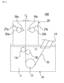
FIG. 1 is a schematic diagram of a gas wiping device as an embodiment of the present invention. -
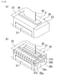
FIG. 2 is a perspective view for (a) depicting a box-shaped body in the gas wiping device shown inFIG. 1 , and (b) explaining the internal structure of the box-shaped body shown in (a). -
FIG. 3 is a transparent top view of the box-shaped body in the gas wiping device shown inFIG. 1 . -
FIG. 4 is an enlarged view of the box-shaped body in the gas wiping device shown inFIG. 1 . -
FIG. 5 is a schematic sectional view of gas wiping nozzles in a gas wiping device as a modification of the present invention. - Hereinafter, a gas wiping device as an embodiment of the present invention will be described with reference to the drawings.
- As shown in
FIG. 1 , agas wiping device 100 as an embodiment of the present invention is installed on aplating bath 10 havingmolten metal 11 stored therein, and has a box-shaped body 20 disposed on top of theplating bath 10. - Inside the
plating bath 10, there are disposed: a main-roller 12 andsub-rollers steel band 30 upward from theplating bath 10; and aninlet 14 for conveying thesteel band 30 from the outside (e.g. a furnace) into theplating bath 10. - As shown in
FIG. 2(a) , the box-shaped body 20 includes: amain body 21 having substantially a tubular shape;end caps main body 21; and anoutlet 24 for sending thesteel band 30 plated with molten metal from the inside thereof to the outside thereof. The box-shaped body 20 is equipped with a sealingcurtain 31 that is closed to ensure hermeticity during manufacturing of plated steel bands and opened at the time of discharging of dross in such a sealed box. - Furthermore, as shown in
FIGS. 1 and2(b) , thegas wiping device 100 includes inside the box-shaped body 20:tubular members steel band 30; gas wiping nozzles (a firstgas wiping nozzle 26a and a secondgas wiping nozzle 26b) connected respectively to thetubular members steel band 30; andaccordion curtains tubular members shaped body 20. - The
gas wiping nozzle 26a has nozzles each having a slit of predetermined width formed thereon, which make it possible to spray gas over substantially whole areas in the width direction inside the box-shaped body 20, and includes afirst spraying segment 26a1 (betweenimaginary lines FIG. 3 ), asecond spraying segment 26a2 (betweenimaginary line 26a4 and the inner wall of theend cap 22 of the box-shaped body 20 inFIG. 3 ) and athird spraying segment 26a3 (betweenimaginary line 26a5 and the inner wall of theend cap 23 of the box-shaped body 20 inFIG. 3 ). - The
first spraying segment 26a1 serves as removing excess molten metal adhering on the surface (opposed to thefirst spraying segment 26a1) of thesteel band 30, and is configured such that it is capable of spraying gas over the full width of thesteel band 30. Thesecond spraying segment 26a2 is configured such that it is capable of spraying gas toward thegas wiping nozzle 26b from one end of thefirst spraying segment 26a1 to the inner wall of theend cap 22 of the box-shapedbody 20 in the width direction. Thethird spraying segment 26a3 is configured such that it is capable of spraying gas toward thegas wiping nozzle 26b from the other end of thefirst spraying segment 26a1 to the inner wall of theend cap 23 of the box-shapedbody 20 in the width direction. - The first, second, and
third spraying segments steel band 30 in the width direction. The positions (boundaries), by which the first, second, andthird spraying segments 26a 2 26a3 are separated, are changed depending on the size of thesteel band 30 in the width direction. - In a similar fashion to that of the
gas wiping nozzle 26a, thegas wiping nozzle 26b has nozzles capable of spraying gas over the whole areas in the width direction inside the box-shapedbody 20, and has afourth spraying segment 26b1 (betweenimaginary lines FIG. 3 ), afifth spraying segment 26b2 (betweenimaginary line 26b4 and the inner wall of theend cap 22 of the box-shapedbody 20 inFIG. 3 ), and asixth spraying segment 26b3 (betweenimaginary line 26b5 and the inner wall of theend cap 23 of the box-shapedbody 20 inFIG. 3 ). - The
fourth spraying segment 26b1 serves as removing excess molten metal adhering on the surface (opposed to thefourth spraying segment 26b1) of thesteel band 30 and is configured such that it is capable of spraying gas over the full width of thesteel band 30. Thefifth spraying segment 26b2 is configured such that it is capable of spraying gas toward thegas wiping nozzle 26a from one end of thefourth spraying segment 26b1 to the inner wall of theend cap 22 of the box-shapedbody 20 in the width direction. Thesixth spraying segment 26b3 is configured such that it is capable of spraying gas toward thegas wiping nozzle 26b from the other end of thefourth spraying segment 26b1 to the inner wall of theend cap 23 of the box-shapedbody 20 in the width direction. - In a similar fashion to that of the first, second, and
third spraying segments sixth spraying segments steel band 30 in the width direction. The positions (boundaries), by which separating the fourth, fifth, andsixth spraying segments steel band 30 in the width direction. - The
gas wiping nozzle 26a, which communicates with the inside of thetubular member 25a, is configured such that gas sent from an exterior into thetubular member 25a through the above-mentioned gas pipe (not shown) is sprayed from the tips of thegas wiping nozzle 26a (the tips of the first, second, andthird spraying segments steel band 30. In a similar fashion, thetubular member 25b, which communicates with thegas wiping nozzle 26b, is configured such that gas sent from an exterior into thetubular member 25b through the above-mentioned gas pipe (not shown) is sprayed from the tips of thegas wiping nozzle 26b (the tips of the fourth, fifth, andsixth spraying segments steel band 30. The end caps 22, 23 have an accordion structure in such a fashion that the gas pipe is movable in a longitudinal and lateral direction inFIG. 3 . - According to the structures described above, area A in
FIG. 3 surrounded by an imaginary line (not shown) connecting theimaginary lines second spraying segment 26a2, thefifth spraying segment 26b2, and the inner wall of theend cap 22 of the box-shapedbody 20 can be sealed between the spaces above and below the nozzle plane connecting the tips of thegas wiping nozzles second spraying segment 26a2 sprays gas in the same direction as that of thefirst spraying segment 26a1, but the former does not serve as removing excess molten metal adhering on the surface of thesteel band 30, and instead, serves as working with thefifth spraying segment 26b2 to seal the area A between the spaces above and below the nozzle plane as a boundary. - In a similar fashion, area B in
FIG. 3 surrounded by an imaginary line (not shown) connecting theimaginary lines third spraying segment 26a3, thesixth spraying segment 26b3, and the inner wall of theend cap 22 of the box-shapedbody 20 can be sealed between the spaces above and below the nozzle plane connecting the tips of thegas wiping nozzles third spraying segment 26a3 sprays gas in the same direction as that of thefirst spraying segment 26a1, but thesegment 26a3 does not serve as removing excess molten metal adhering on the surface of thesteel band 30, and instead, serves as working with thesixth spraying segment 26b3 to seal the area B between the spaces above and below the nozzle plane as a boundary. - As shown by arrows around the
tubular member 25a inFIG. 4 , thetubular member 25a is configured such that it is movable in a longitudinal and lateral direction inFIG. 4 , and that, for example, thegas wiping nozzle 26a is allowed to move while maintained substantially in parallel with thegas wiping nozzle 26b. A distance between thegas wiping nozzle 26a and thegas wiping nozzle 26b is adjusted as one of the ways to control the thickness of molten metal plating formed on thesteel band 30. In a similar fashion (not shown) to that of thetubular member 25a, thetubular member 25b is also configured such that it is movable in a longitudinal and lateral direction inFIG. 4 . The distance between thegas wiping nozzle 26a and thegas wiping nozzle 26b can be changed within a predetermined range by moving one or both of thegas wiping nozzles FIG. 4 . - The
accordion curtains such accordion curtains tubular member 25a and the inner wall (an inner wall closer to thetubular member 25a) of the box-shapedbody 20, and a gap between thetubular member 25b and the inner wall (an inner wall closer to thetubular member 25b) of the box-shapedbody 20 can be sealed, respectively. As an alternative to such an accordion curtain, another partition member may be partition plates having one fixed to the outer wall of the tubular member 25 and the other fixed to the inner wall of the box-shapedbody 20, which are arranged to overlap each other in a vertical direction. - Next, the operation of the
gas wiping device 100 will be described. As shown inFIG. 1 , thesteel band 30 is conveyed from the outside through aninlet 14 into the platingbath 10 to be immersed inmolten metal 11 in theplating bath 10. Subsequently, thesteel band 30 is sent through the main-roller 12 and sub-rollers 13a, 13b into the box-shapedbody 20. Thesteel band 30 conveyed into the box-shapedbody 20 is allowed to pass through between thegas wiping nozzles FIG. 2(a) ) to the outside of the box-shapedbody 20. When passing between thegas wiping nozzles steel band 30 from thegas wiping nozzles tubular members molten metal 11 adhering on the surface of thesteel band 30, thereby adjusting the thickness of the plated layer ofmolten metal 11 to reach the intended thickness. As shown inFIG. 4 , such an operation generatessplashes 40 flying around in the box-shaped body 20 (more specifically, below the nozzle plane). Therefore, the splashes must be prevented from moving toward the passage of thesteel band 30 located above the nozzle plane. - However, as mentioned above, the
gas wiping nozzles FIG. 4 , which makes it difficult to seal a gap between thegas wiping nozzles gas wiping nozzles fifth spraying segments gas wiping nozzles sixth spraying segments gas wiping nozzles splashes 40 at both ends of thegas wiping nozzles upper space 50 in the box-shapedbody 20. - Gaps between the
gas wiping nozzles gas wiping nozzles gas wiping nozzle 26a and/or thegas wiping nozzle 26b are movable. In addition, the high temperature around the gas wiping nozzles may cause a deformation of such blocking members to seal a gap between thegas wiping nozzles steel band 30, or the like). In this regard, thegas wiping device 100 in this embodiment poses no obstruction to a parallel shift of thegas wiping nozzle 26a and/or thegas wiping nozzle 26b irrespective of whether the distance is the maximum or minimum distance between thegas wiping nozzles gas wiping nozzles steel band 30 located above the nozzle plane. In addition, the device is free from concern about problems such as those caused by thermally deformed members contacting thesteel band 30, which may occur if the device has blocking members to seal a gap between thegas wiping nozzles - In addition, the
accordion curtains tubular member 25a and the inner wall of the box-shaped body 20 (the inner wall closer to thetubular member 25a), and a gap between thetubular member 25b and the inner wall of the box-shaped body 20 (the inner wall closer to thetubular member 25b), thereby preventingsplashes 40 from flying away to theupper space 50 of the box-shapedbody 20. As a result, splashes generated below the nozzle plane are prevented from moving toward the passage of thesteel band 30 located above the nozzle plane. In view of the prevention of splashes, it is preferable that theaccordion curtains - Furthermore, since the gas (e.g. nitrogen gas) is sprayed between the
gas wiping nozzles steel band 30 located above the nozzle plane. - Hot-dipped-Zn 6-mass%-A1 2.9-mass%-Mg system plated steel sheets were manufactured by using the gas wiping device shown in
FIG. 2(b) . As a comparative example, hot-dipped-Zn 6-mass%-Al 2.9-mass%-Mg system plated steel sheets were manufactured by using a gas wiping device obtained by removing the spraying segments 26 from the gas wiping device shown inFIG. 2(b) . Table 1 shows the ratio of the number of spots generated by crystallization of the Zn11Mg2 system phase per unit area on the plated steel sheets manufactured under the conditions that the ratio of the number of spots generated in the comparative example is set at 1. The results show that the gas wiping device according to the present invention can greatly reduce the occurrence of a splash-induced spotty appearance. -
(Table 1) Present invention Comparative example Generated spot number ratio 0.5 1 - As described above, the
gas wiping device 100 in this embodiment has the curtains sealing a gap between thetubular member 25a and the inner wall of the box-shaped body 20 (closer to thetubular member 25a), and a gap between thetubular member 25b and the inner wall of the box-shaped body 20 (closer to thetubular member 25b), thereby preventing splashes from moving through the gaps toward the passage of thesteel band 30 located above the nozzle plane. The device also prevents splashes at both ends in the width direction of thegas wiping nozzles steel band 30 located above the nozzle plane. As a result, splashes generated below the nozzle plane are prevented in all areas except for the nozzle widths of thegas wiping nozzles steel band 30 located above the nozzle plane. Therefore, even equipped with a box-shapedbody 20 housing thegas wiping nozzles steel band 30 after excess molten metal is removed from thesteel band 30 by thegas wiping nozzles - In addition, the splashes can be prevented from moving toward the passage of the steel band located above the nozzle plane irrespective of the distance between the
gas wiping nozzles gas wiping nozzle 26a and/or thegas wiping nozzle 26b. - The present invention is not limited to the embodiments described above, but its scope includes various modifications allowable in accordance with the intent of the present invention. For example, the slit width may be smaller for the segment (the
second spraying segment 26a2) that does not spray gas on thesteel band 30 even when thesteel band 30 of the maximum width passes between thegas wiping nozzles first spraying segment 27a1, because the segment sprays gas whose amount is sufficient for sealing. In a similar fashion, the slit width of nozzles for the third, fifth, andsixth spraying segments steel band 30 even when thesteel band 30 of the maximum width passes) than those of the first andfourth spraying segments sixth spraying segments steel band 30, it is possible to discourage excessive gas consumption by allowing the segments to regulate the spraying amount of gas while preventing splashes at both ends in the width direction of thegas wiping nozzles gas wiping nozzles steel band 30 are sealed by gas. Thus, splashes can be prevented from moving toward the passage of thesteel band 30 located above the nozzle plane at all times irrespective of any distance between thegas wiping nozzles sixth spraying segments sixth spraying segments fourth spraying segments planar members 50 with an adjustable inclination angle in the vicinity of the second, third, fifth, andsixth spraying segments FIG. 5 ). It must be noted that the gas regulating unit is not limited to the one shown inFIG. 5 . The unit may be in any form as long as it can regulate the spraying amount of gas. -
- 10
- plating bath
- 11
- molten metal
- 12
- main-roller
- 13a, 13b
- sub-rollers
- 14
- inlet
- 20
- box-shaped body
- 21
- main body
- 22, 23
- end caps
- 24
- outlet
- 25a, 25b
- tubular members
- 26a, 26b
- gas wiping nozzles
- 26a1
- first spraying segment
- 26a2
- second spraying segment
- 26a3
- third spraying segment
- 26b1
- fourth spraying segment
- 26b2
- fifth spraying segment
- 26b3
- sixth spraying segment
- 27a, 27b
- accordion curtains
- 30
- steel band
- 31
- sealing curtain
- 40
- splashes
- 50
- upper space
- 100
- gas wiping device
Claims (3)
- A gas wiping device characterized by comprising:a first gas wiping nozzle and a second gas wiping nozzle arranged to face each other across a steel band pulled up from a molten-metal plating bath, the first and second gas wiping nozzles capable of removing excess molten metal adhering on a surface of the steel band;a first tubular member disposed along a width direction of the steel band, the first tubular member connected to the first gas wiping nozzle;a second tubular member disposed along a width direction of the steel band, the second tubular member connected to the second gas wiping nozzle;a box-shaped body housing the first and second gas wiping nozzles, and the first and second tubular members;a first partition member having one end thereof fixed to an outer wall of the first tubular member, and having the other end thereof fixed to an inner wall of the box-shaped body; anda second partition member having one end thereof fixed to an outer wall of the second tubular member, and having the other end thereof fixed to an inner wall of the box-shaped body, whereinthe first gas wiping nozzle includesa first spraying segment capable of spraying gas over a range as a whole in a width direction of the steel band,a second spraying segment capable of spraying gas toward the second gas wiping nozzle over a range from one end of the first spraying segment to one inner wall of the box-shaped body in a width direction of the box-shaped body, anda third spraying segment capable of spraying gas toward the second gas wiping nozzle over a range from the other end of the first spraying segment to the other inner wall of the box-shaped body in a width direction of the box-shaped body, and whereinthe second gas wiping nozzle includesa fourth spraying segment capable of spraying gas over a range as a whole in a width direction of the steel band,a fifth spraying segment capable of spraying gas toward the first gas wiping nozzle, from over a range from one end of the fourth spraying segment to one inner wall of the box-shaped body in a width direction of the box-shaped body, anda sixth spraying segment capable of spraying gas toward the first gas wiping nozzle over a range from the other end of the fourth spraying segment to the other inner wall of the box-shaped body in a width direction of the box-shaped body.
- The gas wiping device according to claim 1, wherein
the second and third spraying segments are configured such that gas sprayed therefrom is smaller in amount than gas sprayed from the first spraying segment, and wherein
the fifth and sixth spraying segments are configured such that gas sprayed therefrom is smaller in amount than gas sprayed from the fourth spraying segment. - The gas wiping device according to claim 1, wherein
at least one of the first and second gas wiping nozzles is movable relative to the other while being in parallel with the other so that a distance therebetween can be changed within a predetermined range, and wherein
said gas wiping device further comprises a gas regulating unit configured to regulate a spraying amount of gas in such a fashion that, in accordance with a distance between the first and second gas wiping nozzles, gas sprayed from the second spraying segment and gas sprayed from the fifth spraying segment contact each other, and gas sprayed from the third spraying segment and gas sprayed from the sixth spraying segment contact each other.
Priority Applications (1)
| Application Number | Priority Date | Filing Date | Title |
|---|---|---|---|
| PL11836071T PL2634284T3 (en) | 2010-10-26 | 2011-10-18 | Gas wiping device |
Applications Claiming Priority (3)
| Application Number | Priority Date | Filing Date | Title |
|---|---|---|---|
| JP2010239833 | 2010-10-26 | ||
| JP2011226293A JP5221733B2 (en) | 2010-10-26 | 2011-10-14 | Gas wiping device |
| PCT/JP2011/073883 WO2012056935A1 (en) | 2010-10-26 | 2011-10-18 | Gas wiping device |
Publications (3)
| Publication Number | Publication Date |
|---|---|
| EP2634284A1 true EP2634284A1 (en) | 2013-09-04 |
| EP2634284A4 EP2634284A4 (en) | 2016-04-20 |
| EP2634284B1 EP2634284B1 (en) | 2017-12-27 |
Family
ID=45993649
Family Applications (1)
| Application Number | Title | Priority Date | Filing Date |
|---|---|---|---|
| EP11836071.8A Not-in-force EP2634284B1 (en) | 2010-10-26 | 2011-10-18 | Gas wiping device |
Country Status (14)
| Country | Link |
|---|---|
| US (1) | US9004000B2 (en) |
| EP (1) | EP2634284B1 (en) |
| JP (1) | JP5221733B2 (en) |
| KR (1) | KR101367290B1 (en) |
| CN (1) | CN103189540B (en) |
| AU (1) | AU2011321687B2 (en) |
| BR (1) | BR112013010094B1 (en) |
| ES (1) | ES2661573T3 (en) |
| MX (1) | MX2013004703A (en) |
| MY (1) | MY168703A (en) |
| PL (1) | PL2634284T3 (en) |
| TR (1) | TR201802724T4 (en) |
| TW (1) | TWI500818B (en) |
| WO (1) | WO2012056935A1 (en) |
Cited By (6)
| Publication number | Priority date | Publication date | Assignee | Title |
|---|---|---|---|---|
| WO2014199194A1 (en) * | 2013-06-10 | 2014-12-18 | Arcelormittal Investigacion Y Desarrollo, S.L. | Installation for hot dip coating a metal strip comprising an adjustable confinement box |
| WO2015092493A1 (en) * | 2013-12-20 | 2015-06-25 | Arcelormittal Investigacion Y Desarrollo, S.L. | Process for producing a znalmg-coated metal sheet with optimized wiping and corresponding metal sheet |
| US9816168B2 (en) | 2013-12-20 | 2017-11-14 | Arcelormittal | Method for producing a sheet having a ZnAlMg coating with optimized wiping |
| WO2019002573A1 (en) * | 2017-06-30 | 2019-01-03 | Tata Steel Nederland Technology B.V. | Hot dip coating device and method |
| ES2725126R1 (en) * | 2016-05-17 | 2019-09-27 | Dongkuk Steel Mill Co Ltd | APPARATUS TO FORM A NITROGEN CLOUD TO MANUFACTURE A HOT IMMERSION COATED STEEL SHEET WITH EXCELLENT QUALITY OF THE SURFACE AREA AND METHOD FOR MANUFACTURING A HOT COATED IMMERSION STEEL PLATE AND ALUMINUM USING THE MYSELF. |
| WO2022053927A1 (en) | 2020-09-08 | 2022-03-17 | Arcelormittal | Filtration system |
Families Citing this family (7)
| Publication number | Priority date | Publication date | Assignee | Title |
|---|---|---|---|---|
| EP2703515A1 (en) * | 2012-09-03 | 2014-03-05 | voestalpine Stahl GmbH | Method for applying a protective cover to a flat steel product and flat steel product with such a protective cover |
| KR102442759B1 (en) * | 2016-12-22 | 2022-09-13 | 타타 스틸 이즈무이덴 베.뷔. | Nozzles for air scrubbers and air scrubbers |
| US11384419B2 (en) * | 2019-08-30 | 2022-07-12 | Micromaierials Llc | Apparatus and methods for depositing molten metal onto a foil substrate |
| WO2021048593A1 (en) * | 2019-09-10 | 2021-03-18 | Arcelormittal | Moveable overflow for continuous hot-dip coating equipments |
| JP7398285B2 (en) * | 2020-01-24 | 2023-12-14 | 日鉄鋼板株式会社 | Manufacturing method of plated metal plate using seal box |
| US11642690B1 (en) * | 2021-11-05 | 2023-05-09 | GM Global Technology Operations LLC | Systems and methods for paint application during paint submersion |
| CN116692551B (en) * | 2022-02-28 | 2026-01-30 | 宁德时代新能源科技股份有限公司 | Material belt turning mechanism, drying device and electrode manufacturing equipment |
Family Cites Families (20)
| Publication number | Priority date | Publication date | Assignee | Title |
|---|---|---|---|---|
| US3667425A (en) * | 1971-03-01 | 1972-06-06 | Inland Steel Co | Apparatus for controlling coating thickness |
| US4321884A (en) * | 1981-01-22 | 1982-03-30 | National Steel Corporation | Coating thickness control nozzle |
| US4418100A (en) * | 1982-02-02 | 1983-11-29 | Republic Steel Corporation | Apparatus and method for reducing spangle in galvanized products |
| JPS62193671A (en) | 1986-02-19 | 1987-08-25 | Sumitomo Metal Ind Ltd | Wiping device for coating liquid belt-like object |
| JPH0639678B2 (en) * | 1988-02-16 | 1994-05-25 | 川崎製鉄株式会社 | Gas wiping device |
| AU621142B2 (en) * | 1988-08-24 | 1992-03-05 | Australian Wire Industries Pty Ltd | Jet wiping nozzle |
| DE4010801C2 (en) * | 1990-04-04 | 1998-07-23 | Unitas Sa | Device for stripping running tape material |
| US5221345A (en) * | 1990-10-12 | 1993-06-22 | National Galvanizing Inc. | Method and apparatus for coating a strip |
| JPH06158261A (en) * | 1992-11-30 | 1994-06-07 | Nippon Steel Corp | Method for controlling the amount of molten metal plating |
| JPH06256923A (en) * | 1993-03-08 | 1994-09-13 | Kobe Steel Ltd | Gas wiping method and its device for hot dip plating line |
| JP2980016B2 (en) * | 1995-11-22 | 1999-11-22 | 住友金属工業株式会社 | Edge overcoat prevention device |
| JP3179401B2 (en) | 1996-12-13 | 2001-06-25 | 日新製鋼株式会社 | Hot-dip Zn-Al-Mg plated steel sheet with good corrosion resistance and surface appearance and method for producing the same |
| JP3788122B2 (en) * | 1999-08-06 | 2006-06-21 | Jfeスチール株式会社 | Gas wiping device |
| JP4046042B2 (en) * | 2003-08-20 | 2008-02-13 | Jfeスチール株式会社 | Wiping equipment for continuous hot dipping |
| JP4598425B2 (en) * | 2004-03-30 | 2010-12-15 | 新日本製鐵株式会社 | Eddy current sensor correction method, hot-dip coating weight control apparatus and control method |
| JP4451194B2 (en) * | 2004-04-13 | 2010-04-14 | 三菱日立製鉄機械株式会社 | Liquid wiping device |
| SE529060C2 (en) * | 2005-06-30 | 2007-04-24 | Abb Ab | Thickness-controlling device for metallic coating on elongated metallic strip comprises second wiper associated with respective electromagnetic wiper and designed to apply jet of gas to strip |
| CN2844136Y (en) * | 2005-07-29 | 2006-12-06 | 宝山钢铁股份有限公司 | Double-nozzle coating airblade device |
| KR100843923B1 (en) * | 2006-12-08 | 2008-07-03 | 주식회사 포스코 | Multi-stage nozzle type gas wiping device |
| JP5602371B2 (en) * | 2009-03-06 | 2014-10-08 | 三菱日立製鉄機械株式会社 | Gas wiping device |
-
2011
- 2011-10-14 JP JP2011226293A patent/JP5221733B2/en active Active
- 2011-10-18 ES ES11836071.8T patent/ES2661573T3/en active Active
- 2011-10-18 AU AU2011321687A patent/AU2011321687B2/en not_active Ceased
- 2011-10-18 WO PCT/JP2011/073883 patent/WO2012056935A1/en not_active Ceased
- 2011-10-18 MY MYPI2013001483A patent/MY168703A/en unknown
- 2011-10-18 MX MX2013004703A patent/MX2013004703A/en active IP Right Grant
- 2011-10-18 EP EP11836071.8A patent/EP2634284B1/en not_active Not-in-force
- 2011-10-18 TR TR2018/02724T patent/TR201802724T4/en unknown
- 2011-10-18 CN CN201180051936.1A patent/CN103189540B/en not_active Expired - Fee Related
- 2011-10-18 KR KR1020137013110A patent/KR101367290B1/en not_active Expired - Fee Related
- 2011-10-18 PL PL11836071T patent/PL2634284T3/en unknown
- 2011-10-18 BR BR112013010094-0A patent/BR112013010094B1/en not_active IP Right Cessation
- 2011-10-26 TW TW100138851A patent/TWI500818B/en not_active IP Right Cessation
-
2013
- 2013-04-24 US US13/869,776 patent/US9004000B2/en not_active Expired - Fee Related
Cited By (16)
| Publication number | Priority date | Publication date | Assignee | Title |
|---|---|---|---|---|
| US10752982B2 (en) | 2013-06-10 | 2020-08-25 | Arcelormittal | Installation for hot dip coating a metal strip comprising an adjustable confinement box |
| WO2014199292A1 (en) * | 2013-06-10 | 2014-12-18 | Arcelormittal Investigacion Y Desarrollo, S.L. | Installation for hot dip coating a metal strip comprising an adjustable confinement box |
| WO2014199194A1 (en) * | 2013-06-10 | 2014-12-18 | Arcelormittal Investigacion Y Desarrollo, S.L. | Installation for hot dip coating a metal strip comprising an adjustable confinement box |
| WO2015092493A1 (en) * | 2013-12-20 | 2015-06-25 | Arcelormittal Investigacion Y Desarrollo, S.L. | Process for producing a znalmg-coated metal sheet with optimized wiping and corresponding metal sheet |
| CN106029933A (en) * | 2013-12-20 | 2016-10-12 | 安赛乐米塔尔公司 | Process for producing a znalmg-coated metal sheet with optimized wiping and corresponding metal sheet |
| US9816168B2 (en) | 2013-12-20 | 2017-11-14 | Arcelormittal | Method for producing a sheet having a ZnAlMg coating with optimized wiping |
| RU2647967C2 (en) * | 2013-12-20 | 2018-03-21 | Арселормиттал | PROCESS FOR PRODUCING ZnAlMg-COATED METAL SHEET WITH OPTIMISED WIPING AND CORRESPONDING METAL SHEET |
| EP3084031B1 (en) | 2013-12-20 | 2018-04-04 | Arcelormittal | Process for producing a znalmg-coated metal sheet with optimized wiping and corresponding metal sheet |
| US10138538B2 (en) | 2013-12-20 | 2018-11-27 | Arcelormittal | ZnAlMg-coated metal sheet produced by optimized wiping |
| ES2725126R1 (en) * | 2016-05-17 | 2019-09-27 | Dongkuk Steel Mill Co Ltd | APPARATUS TO FORM A NITROGEN CLOUD TO MANUFACTURE A HOT IMMERSION COATED STEEL SHEET WITH EXCELLENT QUALITY OF THE SURFACE AREA AND METHOD FOR MANUFACTURING A HOT COATED IMMERSION STEEL PLATE AND ALUMINUM USING THE MYSELF. |
| WO2019002573A1 (en) * | 2017-06-30 | 2019-01-03 | Tata Steel Nederland Technology B.V. | Hot dip coating device and method |
| US11761073B2 (en) | 2017-06-30 | 2023-09-19 | Tata Steel Nederland Technology B.V. | Hot dip coating device and method |
| US12595541B2 (en) | 2017-06-30 | 2026-04-07 | Tata Steel Nederland Technology B.V. | Hot dip coating device and method |
| WO2022053927A1 (en) | 2020-09-08 | 2022-03-17 | Arcelormittal | Filtration system |
| WO2022053847A1 (en) | 2020-09-08 | 2022-03-17 | Arcelormittal | Filtration system |
| CN115867686A (en) * | 2020-09-08 | 2023-03-28 | 安赛乐米塔尔公司 | Filter system |
Also Published As
| Publication number | Publication date |
|---|---|
| JP2012107322A (en) | 2012-06-07 |
| BR112013010094B1 (en) | 2020-03-10 |
| AU2011321687B2 (en) | 2015-02-19 |
| EP2634284A4 (en) | 2016-04-20 |
| WO2012056935A1 (en) | 2012-05-03 |
| TR201802724T4 (en) | 2018-03-21 |
| MX2013004703A (en) | 2013-05-22 |
| US9004000B2 (en) | 2015-04-14 |
| AU2011321687A1 (en) | 2013-05-02 |
| PL2634284T3 (en) | 2018-06-29 |
| KR20130069864A (en) | 2013-06-26 |
| CN103189540B (en) | 2014-09-24 |
| US20130239884A1 (en) | 2013-09-19 |
| JP5221733B2 (en) | 2013-06-26 |
| EP2634284B1 (en) | 2017-12-27 |
| MY168703A (en) | 2018-11-29 |
| CN103189540A (en) | 2013-07-03 |
| ES2661573T3 (en) | 2018-04-02 |
| KR101367290B1 (en) | 2014-02-27 |
| BR112013010094A2 (en) | 2016-08-02 |
| TWI500818B (en) | 2015-09-21 |
| TW201229318A (en) | 2012-07-16 |
Similar Documents
| Publication | Publication Date | Title |
|---|---|---|
| EP2634284B1 (en) | Gas wiping device | |
| EP2634283B1 (en) | Gas wiping device | |
| KR101461746B1 (en) | Inoxidizable Gas Wiping Apparatus | |
| KR101758715B1 (en) | Method for producing zinc-aluminum alloy-coated steel sheet with corrosion resistance | |
| SK5392003A3 (en) | Method and installation for dip coating of a metal strip, in particular a steel strip | |
| KR20210022126A (en) | Manufacturing method of hot-dip metal plating steel strip and continuous hot-dip metal plating equipment | |
| KR101758717B1 (en) | Apparatus for producing zinc-aluminum alloy-coated steel sheet with superior workability and corrosion resistance and manufacturing method using the same | |
| JP2020503439A (en) | Alloy-plated steel excellent in crack resistance and method for producing the same | |
| US9863029B2 (en) | Apparatus for forming nitrogen cloud to produce hot dip coated steel sheet | |
| JPH05306449A (en) | Method of preventing molten metal droplets from adhering to the strip surface during molten metal plating | |
| KR20160057998A (en) | Production method for zn-al alloy coated steel sheet and its production device | |
| JPWO2020039869A1 (en) | Method for producing hot-dip galvanized steel strip and continuous hot-dip galvanizing equipment | |
| WO2025088362A1 (en) | Installation for continuously hot dip coating a steel strip and method therefore | |
| JPH02285060A (en) | Gas throttling guide plate enclosure and enclosing method | |
| KR20240010922A (en) | Plating apparatus and plating method | |
| JP2002327256A (en) | Continuous hot metal plating method and apparatus | |
| KR20000043870A (en) | Snout for preventing adherence of impurities | |
| JP2007204783A (en) | Hot-dip metal strip production equipment |
Legal Events
| Date | Code | Title | Description |
|---|---|---|---|
| PUAI | Public reference made under article 153(3) epc to a published international application that has entered the european phase |
Free format text: ORIGINAL CODE: 0009012 |
|
| 17P | Request for examination filed |
Effective date: 20130517 |
|
| AK | Designated contracting states |
Kind code of ref document: A1 Designated state(s): AL AT BE BG CH CY CZ DE DK EE ES FI FR GB GR HR HU IE IS IT LI LT LU LV MC MK MT NL NO PL PT RO RS SE SI SK SM TR |
|
| DAX | Request for extension of the european patent (deleted) | ||
| RA4 | Supplementary search report drawn up and despatched (corrected) |
Effective date: 20160321 |
|
| RIC1 | Information provided on ipc code assigned before grant |
Ipc: C23C 2/20 20060101AFI20160315BHEP Ipc: C23C 2/00 20060101ALI20160315BHEP |
|
| 17Q | First examination report despatched |
Effective date: 20161109 |
|
| GRAP | Despatch of communication of intention to grant a patent |
Free format text: ORIGINAL CODE: EPIDOSNIGR1 |
|
| INTG | Intention to grant announced |
Effective date: 20170719 |
|
| GRAS | Grant fee paid |
Free format text: ORIGINAL CODE: EPIDOSNIGR3 |
|
| GRAA | (expected) grant |
Free format text: ORIGINAL CODE: 0009210 |
|
| AK | Designated contracting states |
Kind code of ref document: B1 Designated state(s): AL AT BE BG CH CY CZ DE DK EE ES FI FR GB GR HR HU IE IS IT LI LT LU LV MC MK MT NL NO PL PT RO RS SE SI SK SM TR |
|
| REG | Reference to a national code |
Ref country code: GB Ref legal event code: FG4D |
|
| REG | Reference to a national code |
Ref country code: CH Ref legal event code: EP |
|
| REG | Reference to a national code |
Ref country code: AT Ref legal event code: REF Ref document number: 958364 Country of ref document: AT Kind code of ref document: T Effective date: 20180115 |
|
| REG | Reference to a national code |
Ref country code: IE Ref legal event code: FG4D |
|
| REG | Reference to a national code |
Ref country code: DE Ref legal event code: R096 Ref document number: 602011044615 Country of ref document: DE |
|
| REG | Reference to a national code |
Ref country code: RO Ref legal event code: EPE |
|
| REG | Reference to a national code |
Ref country code: SE Ref legal event code: TRGR |
|
| REG | Reference to a national code |
Ref country code: NL Ref legal event code: FP |
|
| REG | Reference to a national code |
Ref country code: ES Ref legal event code: FG2A Ref document number: 2661573 Country of ref document: ES Kind code of ref document: T3 Effective date: 20180402 |
|
| PG25 | Lapsed in a contracting state [announced via postgrant information from national office to epo] |
Ref country code: NO Free format text: LAPSE BECAUSE OF FAILURE TO SUBMIT A TRANSLATION OF THE DESCRIPTION OR TO PAY THE FEE WITHIN THE PRESCRIBED TIME-LIMIT Effective date: 20180327 Ref country code: LT Free format text: LAPSE BECAUSE OF FAILURE TO SUBMIT A TRANSLATION OF THE DESCRIPTION OR TO PAY THE FEE WITHIN THE PRESCRIBED TIME-LIMIT Effective date: 20171227 |
|
| REG | Reference to a national code |
Ref country code: LT Ref legal event code: MG4D |
|
| PG25 | Lapsed in a contracting state [announced via postgrant information from national office to epo] |
Ref country code: LV Free format text: LAPSE BECAUSE OF FAILURE TO SUBMIT A TRANSLATION OF THE DESCRIPTION OR TO PAY THE FEE WITHIN THE PRESCRIBED TIME-LIMIT Effective date: 20171227 Ref country code: GR Free format text: LAPSE BECAUSE OF FAILURE TO SUBMIT A TRANSLATION OF THE DESCRIPTION OR TO PAY THE FEE WITHIN THE PRESCRIBED TIME-LIMIT Effective date: 20180328 Ref country code: BG Free format text: LAPSE BECAUSE OF FAILURE TO SUBMIT A TRANSLATION OF THE DESCRIPTION OR TO PAY THE FEE WITHIN THE PRESCRIBED TIME-LIMIT Effective date: 20180327 Ref country code: HR Free format text: LAPSE BECAUSE OF FAILURE TO SUBMIT A TRANSLATION OF THE DESCRIPTION OR TO PAY THE FEE WITHIN THE PRESCRIBED TIME-LIMIT Effective date: 20171227 Ref country code: RS Free format text: LAPSE BECAUSE OF FAILURE TO SUBMIT A TRANSLATION OF THE DESCRIPTION OR TO PAY THE FEE WITHIN THE PRESCRIBED TIME-LIMIT Effective date: 20171227 |
|
| REG | Reference to a national code |
Ref country code: SK Ref legal event code: T3 Ref document number: E 26946 Country of ref document: SK |
|
| PG25 | Lapsed in a contracting state [announced via postgrant information from national office to epo] |
Ref country code: EE Free format text: LAPSE BECAUSE OF FAILURE TO SUBMIT A TRANSLATION OF THE DESCRIPTION OR TO PAY THE FEE WITHIN THE PRESCRIBED TIME-LIMIT Effective date: 20171227 Ref country code: CY Free format text: LAPSE BECAUSE OF FAILURE TO SUBMIT A TRANSLATION OF THE DESCRIPTION OR TO PAY THE FEE WITHIN THE PRESCRIBED TIME-LIMIT Effective date: 20171227 |
|
| PG25 | Lapsed in a contracting state [announced via postgrant information from national office to epo] |
Ref country code: SM Free format text: LAPSE BECAUSE OF FAILURE TO SUBMIT A TRANSLATION OF THE DESCRIPTION OR TO PAY THE FEE WITHIN THE PRESCRIBED TIME-LIMIT Effective date: 20171227 Ref country code: IS Free format text: LAPSE BECAUSE OF FAILURE TO SUBMIT A TRANSLATION OF THE DESCRIPTION OR TO PAY THE FEE WITHIN THE PRESCRIBED TIME-LIMIT Effective date: 20180427 |
|
| REG | Reference to a national code |
Ref country code: DE Ref legal event code: R097 Ref document number: 602011044615 Country of ref document: DE |
|
| REG | Reference to a national code |
Ref country code: FR Ref legal event code: PLFP Year of fee payment: 8 |
|
| PLBE | No opposition filed within time limit |
Free format text: ORIGINAL CODE: 0009261 |
|
| STAA | Information on the status of an ep patent application or granted ep patent |
Free format text: STATUS: NO OPPOSITION FILED WITHIN TIME LIMIT |
|
| PG25 | Lapsed in a contracting state [announced via postgrant information from national office to epo] |
Ref country code: DK Free format text: LAPSE BECAUSE OF FAILURE TO SUBMIT A TRANSLATION OF THE DESCRIPTION OR TO PAY THE FEE WITHIN THE PRESCRIBED TIME-LIMIT Effective date: 20171227 |
|
| 26N | No opposition filed |
Effective date: 20180928 |
|
| PG25 | Lapsed in a contracting state [announced via postgrant information from national office to epo] |
Ref country code: SI Free format text: LAPSE BECAUSE OF FAILURE TO SUBMIT A TRANSLATION OF THE DESCRIPTION OR TO PAY THE FEE WITHIN THE PRESCRIBED TIME-LIMIT Effective date: 20171227 |
|
| REG | Reference to a national code |
Ref country code: CH Ref legal event code: PL |
|
| PG25 | Lapsed in a contracting state [announced via postgrant information from national office to epo] |
Ref country code: MC Free format text: LAPSE BECAUSE OF FAILURE TO SUBMIT A TRANSLATION OF THE DESCRIPTION OR TO PAY THE FEE WITHIN THE PRESCRIBED TIME-LIMIT Effective date: 20171227 |
|
| REG | Reference to a national code |
Ref country code: IE Ref legal event code: MM4A |
|
| PG25 | Lapsed in a contracting state [announced via postgrant information from national office to epo] |
Ref country code: CH Free format text: LAPSE BECAUSE OF NON-PAYMENT OF DUE FEES Effective date: 20181031 Ref country code: LI Free format text: LAPSE BECAUSE OF NON-PAYMENT OF DUE FEES Effective date: 20181031 |
|
| PG25 | Lapsed in a contracting state [announced via postgrant information from national office to epo] |
Ref country code: IE Free format text: LAPSE BECAUSE OF NON-PAYMENT OF DUE FEES Effective date: 20181018 |
|
| PGFP | Annual fee paid to national office [announced via postgrant information from national office to epo] |
Ref country code: RO Payment date: 20190923 Year of fee payment: 9 Ref country code: CZ Payment date: 20190925 Year of fee payment: 9 Ref country code: SK Payment date: 20190924 Year of fee payment: 9 |
|
| PGFP | Annual fee paid to national office [announced via postgrant information from national office to epo] |
Ref country code: PL Payment date: 20190923 Year of fee payment: 9 Ref country code: LU Payment date: 20191021 Year of fee payment: 9 |
|
| PG25 | Lapsed in a contracting state [announced via postgrant information from national office to epo] |
Ref country code: MT Free format text: LAPSE BECAUSE OF NON-PAYMENT OF DUE FEES Effective date: 20181018 |
|
| PGFP | Annual fee paid to national office [announced via postgrant information from national office to epo] |
Ref country code: DE Payment date: 20191021 Year of fee payment: 9 Ref country code: SE Payment date: 20191021 Year of fee payment: 9 Ref country code: FI Payment date: 20191022 Year of fee payment: 9 Ref country code: NL Payment date: 20191021 Year of fee payment: 9 |
|
| PGFP | Annual fee paid to national office [announced via postgrant information from national office to epo] |
Ref country code: BE Payment date: 20191021 Year of fee payment: 9 Ref country code: FR Payment date: 20191028 Year of fee payment: 9 Ref country code: IT Payment date: 20191028 Year of fee payment: 9 Ref country code: ES Payment date: 20191122 Year of fee payment: 9 |
|
| PGFP | Annual fee paid to national office [announced via postgrant information from national office to epo] |
Ref country code: AT Payment date: 20191022 Year of fee payment: 9 Ref country code: TR Payment date: 20191015 Year of fee payment: 9 |
|
| PGFP | Annual fee paid to national office [announced via postgrant information from national office to epo] |
Ref country code: GB Payment date: 20191021 Year of fee payment: 9 |
|
| PG25 | Lapsed in a contracting state [announced via postgrant information from national office to epo] |
Ref country code: PT Free format text: LAPSE BECAUSE OF FAILURE TO SUBMIT A TRANSLATION OF THE DESCRIPTION OR TO PAY THE FEE WITHIN THE PRESCRIBED TIME-LIMIT Effective date: 20171227 |
|
| PG25 | Lapsed in a contracting state [announced via postgrant information from national office to epo] |
Ref country code: HU Free format text: LAPSE BECAUSE OF FAILURE TO SUBMIT A TRANSLATION OF THE DESCRIPTION OR TO PAY THE FEE WITHIN THE PRESCRIBED TIME-LIMIT; INVALID AB INITIO Effective date: 20111018 Ref country code: MK Free format text: LAPSE BECAUSE OF NON-PAYMENT OF DUE FEES Effective date: 20171227 |
|
| PG25 | Lapsed in a contracting state [announced via postgrant information from national office to epo] |
Ref country code: AL Free format text: LAPSE BECAUSE OF FAILURE TO SUBMIT A TRANSLATION OF THE DESCRIPTION OR TO PAY THE FEE WITHIN THE PRESCRIBED TIME-LIMIT Effective date: 20171227 |
|
| REG | Reference to a national code |
Ref country code: DE Ref legal event code: R119 Ref document number: 602011044615 Country of ref document: DE |
|
| REG | Reference to a national code |
Ref country code: FI Ref legal event code: MAE |
|
| REG | Reference to a national code |
Ref country code: SE Ref legal event code: EUG |
|
| REG | Reference to a national code |
Ref country code: NL Ref legal event code: MM Effective date: 20201101 |
|
| REG | Reference to a national code |
Ref country code: AT Ref legal event code: MM01 Ref document number: 958364 Country of ref document: AT Kind code of ref document: T Effective date: 20201018 |
|
| GBPC | Gb: european patent ceased through non-payment of renewal fee |
Effective date: 20201018 |
|
| REG | Reference to a national code |
Ref country code: SK Ref legal event code: MM4A Ref document number: E 26946 Country of ref document: SK Effective date: 20201018 |
|
| PG25 | Lapsed in a contracting state [announced via postgrant information from national office to epo] |
Ref country code: LU Free format text: LAPSE BECAUSE OF NON-PAYMENT OF DUE FEES Effective date: 20201018 |
|
| REG | Reference to a national code |
Ref country code: BE Ref legal event code: MM Effective date: 20201031 |
|
| PG25 | Lapsed in a contracting state [announced via postgrant information from national office to epo] |
Ref country code: DE Free format text: LAPSE BECAUSE OF NON-PAYMENT OF DUE FEES Effective date: 20210501 Ref country code: CZ Free format text: LAPSE BECAUSE OF NON-PAYMENT OF DUE FEES Effective date: 20201018 Ref country code: NL Free format text: LAPSE BECAUSE OF NON-PAYMENT OF DUE FEES Effective date: 20201101 Ref country code: SK Free format text: LAPSE BECAUSE OF NON-PAYMENT OF DUE FEES Effective date: 20201018 Ref country code: RO Free format text: LAPSE BECAUSE OF NON-PAYMENT OF DUE FEES Effective date: 20201018 Ref country code: FR Free format text: LAPSE BECAUSE OF NON-PAYMENT OF DUE FEES Effective date: 20201031 Ref country code: FI Free format text: LAPSE BECAUSE OF NON-PAYMENT OF DUE FEES Effective date: 20201018 |
|
| PG25 | Lapsed in a contracting state [announced via postgrant information from national office to epo] |
Ref country code: GB Free format text: LAPSE BECAUSE OF NON-PAYMENT OF DUE FEES Effective date: 20201018 Ref country code: SE Free format text: LAPSE BECAUSE OF NON-PAYMENT OF DUE FEES Effective date: 20201019 Ref country code: BE Free format text: LAPSE BECAUSE OF NON-PAYMENT OF DUE FEES Effective date: 20201031 Ref country code: AT Free format text: LAPSE BECAUSE OF NON-PAYMENT OF DUE FEES Effective date: 20201018 |
|
| PG25 | Lapsed in a contracting state [announced via postgrant information from national office to epo] |
Ref country code: IT Free format text: LAPSE BECAUSE OF NON-PAYMENT OF DUE FEES Effective date: 20201018 |
|
| REG | Reference to a national code |
Ref country code: AT Ref legal event code: UEP Ref document number: 958364 Country of ref document: AT Kind code of ref document: T Effective date: 20171227 |
|
| REG | Reference to a national code |
Ref country code: ES Ref legal event code: FD2A Effective date: 20220128 |
|
| PG25 | Lapsed in a contracting state [announced via postgrant information from national office to epo] |
Ref country code: ES Free format text: LAPSE BECAUSE OF NON-PAYMENT OF DUE FEES Effective date: 20201019 |
|
| PG25 | Lapsed in a contracting state [announced via postgrant information from national office to epo] |
Ref country code: TR Free format text: LAPSE BECAUSE OF NON-PAYMENT OF DUE FEES Effective date: 20201018 |
|
| PG25 | Lapsed in a contracting state [announced via postgrant information from national office to epo] |
Ref country code: PL Free format text: LAPSE BECAUSE OF NON-PAYMENT OF DUE FEES Effective date: 20201018 |