EP2634023B1 - Dispositif d'admission d'air d'un système de ventilation intérieur de véhicule - Google Patents
Dispositif d'admission d'air d'un système de ventilation intérieur de véhicule Download PDFInfo
- Publication number
- EP2634023B1 EP2634023B1 EP12157810.8A EP12157810A EP2634023B1 EP 2634023 B1 EP2634023 B1 EP 2634023B1 EP 12157810 A EP12157810 A EP 12157810A EP 2634023 B1 EP2634023 B1 EP 2634023B1
- Authority
- EP
- European Patent Office
- Prior art keywords
- filter
- air
- air intake
- opening
- fresh air
- Prior art date
- Legal status (The legal status is an assumption and is not a legal conclusion. Google has not performed a legal analysis and makes no representation as to the accuracy of the status listed.)
- Active
Links
- 238000009423 ventilation Methods 0.000 title claims description 22
- 238000012423 maintenance Methods 0.000 claims description 27
- 239000007788 liquid Substances 0.000 claims description 15
- 238000004064 recycling Methods 0.000 claims description 10
- 230000001681 protective effect Effects 0.000 claims description 9
- 238000011144 upstream manufacturing Methods 0.000 claims description 4
- XLYOFNOQVPJJNP-UHFFFAOYSA-N water Substances O XLYOFNOQVPJJNP-UHFFFAOYSA-N 0.000 claims description 2
- 239000000463 material Substances 0.000 description 4
- 238000009434 installation Methods 0.000 description 3
- 238000004378 air conditioning Methods 0.000 description 2
- 238000007789 sealing Methods 0.000 description 2
- 239000000443 aerosol Substances 0.000 description 1
- 230000005494 condensation Effects 0.000 description 1
- 238000009833 condensation Methods 0.000 description 1
- 238000001816 cooling Methods 0.000 description 1
- 238000010438 heat treatment Methods 0.000 description 1
- 230000002209 hydrophobic effect Effects 0.000 description 1
Images


Classifications
-
- B—PERFORMING OPERATIONS; TRANSPORTING
- B60—VEHICLES IN GENERAL
- B60H—ARRANGEMENTS OF HEATING, COOLING, VENTILATING OR OTHER AIR-TREATING DEVICES SPECIALLY ADAPTED FOR PASSENGER OR GOODS SPACES OF VEHICLES
- B60H3/00—Other air-treating devices
- B60H3/06—Filtering
- B60H3/0608—Filter arrangements in the air stream
- B60H3/0616—Filter arrangements in the air stream with provisions for replacing the filter element
-
- B—PERFORMING OPERATIONS; TRANSPORTING
- B60—VEHICLES IN GENERAL
- B60H—ARRANGEMENTS OF HEATING, COOLING, VENTILATING OR OTHER AIR-TREATING DEVICES SPECIALLY ADAPTED FOR PASSENGER OR GOODS SPACES OF VEHICLES
- B60H1/00—Heating, cooling or ventilating [HVAC] devices
- B60H1/00007—Combined heating, ventilating, or cooling devices
- B60H1/00021—Air flow details of HVAC devices
- B60H2001/00078—Assembling, manufacturing or layout details
- B60H2001/00085—Assembling, manufacturing or layout details of air intake
-
- B—PERFORMING OPERATIONS; TRANSPORTING
- B60—VEHICLES IN GENERAL
- B60H—ARRANGEMENTS OF HEATING, COOLING, VENTILATING OR OTHER AIR-TREATING DEVICES SPECIALLY ADAPTED FOR PASSENGER OR GOODS SPACES OF VEHICLES
- B60H3/00—Other air-treating devices
- B60H3/06—Filtering
- B60H3/0608—Filter arrangements in the air stream
- B60H2003/065—Details for holding filter elements in position
Definitions
- the invention relates to an air intake device of a vehicle-interior ventilation system, in particular of a vehicle air conditioner, and to a vehicle-interior ventilation system itself.
- Air intake devices of this type are known from the prior art, the filter maintenance opening being closed by a separate cover which has to be removed for installing and dismantling the filter.
- Document EP 2 078 629 A1 discloses an air intake device according to the preamble of claim 1.
- Vehicle-interior ventilation systems are usually arranged in an interior of the vehicle, the available installation space being limited and it therefore possibly being difficult to reach the filter maintenance opening.
- the fresh air inlet has to be sealed in a complex manner with respect to the surroundings of the interior, in order to avoid an inflow of warm air from the engine compartment.
- an air intake device of a vehicle-interior ventilation system in particular of a vehicle air conditioner, having a filter chamber which is arranged upstream of a fan blower, and a filter which is arranged in the filter chamber, the filter chamber having a fresh air inlet upstream of the filter and a filter maintenance opening which makes it possible to install and dismantle the filter.
- the air intake device comprises an air-guiding component which can be dismantled and has a fresh air intake opening, which air-guiding component forms a fresh air duct which extends from the fresh air intake opening to the fresh air inlet of the filter chamber, and which air-guiding component closes the filter maintenance opening by way of a cover section.
- Fresh air can be sucked in via the fresh air duct independently of the position of the filter chamber in the vehicle. It can be avoided in this way that, for example, heated air in the engine compartment is sucked in. Since the air-guiding component forms the cover for the filter maintenance opening, a simple exchange of the filter is possible, since no separate, additional cover of the filter maintenance opening has to be mounted and dismantled.
- a simple embodiment with a large filter maintenance opening is made possible by the filter maintenance opening extending from the fresh air inlet as far as the fan blower.
- the required individual components can be reduced by the air-guiding component forming a mounting for the filter.
- the air-guiding component is mounted pivotably, in particular on the filter-chamber wall. This makes simple access to the filter maintenance opening possible by pivoting of the air-guiding component.
- the air-guiding component can be connected in a positively locking manner to the filter-chamber wall, preferably by a quick-action locking means. In this way, a reliable connection of the air-guiding component and the filter-chamber wall is ensured, whereas at the same time simple locking and unlocking of the air-guiding component is made possible, preferably without tools.
- the fresh air duct can run in the direction from the fresh air intake opening to the filter maintenance opening and preferably constantly upwards to the fresh air inlet.
- the air-guiding component can have at least one outflow opening for liquid, which outflow opening connects the filter chamber to the fresh air duct, preferably in such a way that liquid which condenses on the filter can run out through the outflow opening into the fresh air duct.
- the air-guiding component can have a dewatering opening at the lowermost point of the fresh air duct, which dewatering opening is preferably arranged in a dead water region of the fresh air duct.
- the fresh air duct can have a groove-shaped dewatering channel which extends from the outflow opening to the dewatering opening, the dewatering channel preferably having a cover.
- the filter in the installed state, is installed such that it is inclined with respect to the horizontal, and the lower end of the filter is arranged at the filter maintenance opening. In this way, the outflow of liquid which condenses on the filter to the filter maintenance opening is ensured.
- the filter has a filter frame which has at least one frame opening which makes an outflow of a liquid which condenses in the filter possible, a frame opening being provided for each filter fold, for example.
- a recycling duct preferably opens into the filter chamber, which recycling duct can be closed by means of a flap, the flap lying remote from the filter maintenance opening such that, during the dismantling, the filter can be moved such that it is remote from the openings which are assigned to the flap. In this way, the installation and dismantling of the filter is not influenced by the flap.
- the air-guiding component is configured in such a way that, in the installed state of the ventilation system, the fresh air duct extends through a protective wall of the vehicle, which protective wall separates an interior of the vehicle from the engine compartment, the filter chamber being arranged in the vehicle interior and the fresh air intake opening being arranged outside the vehicle interior.
- the air-guiding component preferably extends to a dedicated fresh air intake on the engine bonnet side. It is therefore ruled out that hot engine air is sucked in.
- the invention relates to a vehicle-interior ventilation system, in particular a vehicle air conditioner, having an above-described air intake device.
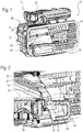
- Figure 1 shows a vehicle-interior ventilation system 10 which is arranged in an interior 12 of a vehicle.
- the interior 12 is separated by a diagrammatically shown protective wall 14 from the engine compartment or another space which is connected to the surroundings of the vehicle.
- the interior 12 of the vehicle is provided behind the protective wall 14 in the perspective illustration of Figure 1 .
- the vehicle-interior ventilation system 10 comprises an air intake device 16 which is suitable for sucking fresh air out of the surroundings or a vehicle space which is connected to the surroundings of the vehicle, or recycled air from the vehicle interior.
- the device 16 is arranged on the left-hand side in the vehicle-interior ventilation system 10 shown.
- the vehicle-interior ventilation system 10 comprises an air conditioning device 30 which is configured for cooling, heating and/or for distributing the air which is sucked in to different ventilation outlets which are assigned, for example, to a windscreen or various air outlet nozzles in the vehicle interior.
- FIG 2 shows a detailed view of a section through the air intake device 16 of the vehicle-interior ventilation system 10.
- a filter chamber 18 is provided in the air intake device 16, having a recycling inlet 20 (see Figure 1 ) and a fresh air inlet 22 which is connected to an air-guiding component 24.
- the air-guiding component 24 forms a fresh air duct 26 which extends through the protective wall 14 out of the interior 12 of the vehicle and connects the fresh air inlet 22 of the filter chamber 18 to a fresh air intake opening 28.
- a filter 32 is provided in the filter chamber 18, which filter 32 is arranged between a fan blower 34 and the recycling inlet 20 or the fresh air inlet 22 and filters the recycled air or fresh air which is sucked in.
- a flap 36 is provided which can optionally close the fresh air inlet 22 or the recycling inlet 20 of the filter chamber 18.
- the recycling inlet 20 of the filter chamber 18 is closed by the flap 36.
- the air-guiding component 24 is attached in a manner which can be dismantled to the housing of the air intake device 16.
- a locking assembly 38 makes positive locking of the air-guiding component 24 to the housing of the air intake device 16 possible.
- Figure 3 shows a sectional view of the air intake device 16 which, in the selected illustration, is positioned substantially on the right-hand side of the protective wall 14 in the interior 12 of the vehicle, the air intake device 16 being arranged at an opening of the protective wall in a manner which is sealed by a sealing device.
- the recycling inlet 20 and the fresh air inlet 22 of the filter chamber 18 are arranged adjacently to one another and in this way can optionally be closed by a flap 36 of compact configuration.
- Figure 3 shows the flap 36 in a position, in which it closes the recycling inlet 20 completely and opens the fresh air inlet 22 completely.
- the filter 32 can be arranged at a position bellow the flap mechanism, as a result of which the filter 32 can be introduced and removed independently of the position of the flap 36.
- the fan blower 34 is arranged bellow the filter chamber 18, which fan blower 34 provides an air flow to the air conditioning device 30 of the vehicle-interior ventilation system 10.
- the filter chamber 18 has a filter maintenance opening 40 which makes it possible to install and dismantle the filter 32.
- the filter 32 can be introduced through the filter maintenance opening 40 into the filter chamber 18 and removed.
- the filter maintenance opening 40 is closed by a cover section 42 of the air-guiding component 24.
- the cover section 42 of the air-guiding component 24 forms an axial mounting for the filter 32, by the section 42 producing an axial stop for the filter 32. In this way, no separate component is required as a cover for the filter maintenance opening 40.
- the filter 32 is installed such that it is inclined with respect to the horizontal. On account of the inclination of the filter 32, a liquid which condenses on the filter flows in the direction of the filter maintenance opening 40. At least one outflow opening 44 is provided in the cover section 42 of the air-guiding component 24, which outflow opening 44 connects the filter chamber 18 to the fresh air duct 26, with the result that the liquid can run out through the outflow opening 44 into the fresh air duct 26.
- the liquid runs in the fresh air duct 26 to a lowest point, at which the fresh air duct 26 has a dewatering opening 46, through which the liquid can exit the air intake device 16 in a defined manner.
- the fresh air inlet 22 is formed completely by a fixedly mounted filter-chamber wall 48, 49.
- the filter maintenance opening 40 extends from the lower filter-chamber wall 49 of the fresh air inlet 22 on the side of the filter 32 as far as the housing of the fan blower 34.
- Figure 4 shows an alternative embodiment, in which the lower section 49 (shown in Fig. 3 ) of the fresh air inlet 22, which section 49 lies on the side of the filter 32, is formed by the air-guiding component 24 which can be dismantled.
- the air-guiding component 24 When the air-guiding component 24 is dismantled, the fresh air inlet 22 therefore forms a common opening with the filter maintenance opening 40. The installation and dismantling of the filter 32 is facilitated by this large common opening.
- the further features are identical with the embodiment which is shown in Figure 3 .
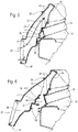
- FIG 5 shows a detailed view of the air-guiding component 24 of the air intake device 16 according to Figure 3 in the mounted position.
- the air-guiding component 24 is mounted on the filter-chamber wall 48 such that it can be pivoted via a pivoting bearing 50.
- the air-guiding component 24 is fixed in the mounted position by a locking assembly 38.
- the locking assembly 38 is configured as a quick-action locking means and is arranged in such a way that it can be reached in a simple way from the fresh air intake opening 28 of the fresh air duct 26 and can preferably be opened and closed manually without additional tools.
- the air-guiding component 24 When the locking assembly 38 is open, the air-guiding component 24 can be pivoted out of its mounting position, as shown in Figure 6 . In the pivoted-out position, the connection of the air-guiding component 24 and the filter-chamber wall 48 on the pivoting bearing 50 can be released and the air-guiding component 24 can be removed completely. In this way, the filter maintenance opening 40 is opened completely and a simple exchange of the filter 32 is made possible.
- projections are provided on the air-guiding component 24 or on the filter-chamber wall 48 or corresponding other housing parts of the air intake device 16, which projections engage into one another in the mounted position of the air-guiding component 24 and form a seal of the filter chamber 18.
- the seal can be configured as a labyrinth seal or can be formed by separate or integrally formed sealing elements.
- Figure 7 shows a perspective rear view of the air-guiding component 24 and the adjoining filter-chamber wall 48 from the side of the filter chamber 18.
- the cover section 42 has two outflow openings 44.
- the air-guiding component 24 is configured in such a way that, in the installed state in the vehicle, it extends to a dedicated fresh air intake on the engine bonnet side. In this way, fresh air is sucked in via the fresh air intake and the air-guiding component 24, and the intake of air which has already been heated from the interior or the engine compartment can be avoided.
- FIG 8 shows a detailed view of the filter 32.
- the filter 32 has a filter frame 52, in which the filter material is received.
- the filter 32 is produced from a hydrophobic material and forms a plurality of filter folds.
- a frame opening 54 is provided in the filter frame 52 at each filter fold, through which frame opening 54 the liquid which condenses in the filter can run out.
- a frame opening is assigned to a plurality of filter folds.
- the liquid in the filter material can accumulate on account of droplets and aerosols transported in the air flow or as a result of condensation on the filter material.
- FIG. 9 shows a locking element 56, having a profiled actuating region 58, a guide projection 60 and two locking projections 62.
- the guide projections 60 make it possible to mount the locking element 56 on the air-guiding component 24 and to displace the locking element 56 linearly in the direction of the locking projections 62 relative to the air-guiding component 24 and the corresponding housing part of the air intake device 16.
- Figure 10 shows the housing component of the air intake device 16 with a projection, in which two locking recesses 64 are provided.
- Figure 11 shows a sectional view through the locking assembly 38 in its locked position, the locking element 56 engaging with the locking projections 62 into the locking recesses 64 of the housing projection. In this way, a positively locking connection is produced which prevents pivoting of the air-guiding component 24 about the pivoting bearing 50.
- FIG. 12 A further embodiment of the air intake device 16 is shown in Figures 12 and 13 .
- a central outflow opening 44 is provided in the cover section 42 of the air-guiding component 24, which outlet opening 44 opens into a groove-shaped dewatering channel 66.
- the dewatering channel 66 extends from the outflow opening 44 to the dewatering opening 46.
- Figure 13 shows the cross section of the fresh air duct 26 with the groove-shaped dewatering channel 66. It is also possible that a plurality of outflow openings 44 are provided with a corresponding plurality of dewatering channels 66, or that a plurality of outflow openings 44 open into a common dewatering channel 66.
- the dewatering channel 66 has a cover 68.
- the flow of the liquid in the dewatering channel 66 is substantially independent of the air flow conditions in the fresh air duct 26.
- the cover 68 is configured in such a way that it bears flushly against the wall of the fresh air duct 26.
Landscapes
- Engineering & Computer Science (AREA)
- Mechanical Engineering (AREA)
- Air-Conditioning For Vehicles (AREA)
Claims (15)
- Dispositif d'admission d'air (16) pour un système de ventilation d'habitacle de véhicule (10), en particulier pour un dispositif de climatisation de véhicule,
comportant une chambre de filtre (18) qui est placée en amont d'un ventilateur de soufflage (34), et un filtre (32) qui est placé dans la chambre de filtre (18), la chambre de filtre (18) comportant une entrée d'air frais (22) en amont du filtre (32) et une ouverture d'entretien de filtre (40) qui permet d'installer et de démonter le filtre (32),
et un composant de guidage d'air (24) qui peut être démonté,
caractérisé en ce que
le composant de guidage d'air comporte une ouverture d'admission d'air frais (28), ledit composant de guidage d'air (24) formant un conduit à air frais (26) qui s'étend de l'ouverture d'admission d'air frais (28) à l'entrée d'air frais (22) de la chambre de filtre (18), et ledit composant de guidage d'air (24) fermant l'ouverture d'entretien de filtre (40) au moyen d'une section formant couvercle (42). - Dispositif d'admission d'air (16) selon la revendication 1, caractérisé en ce que l'ouverture d'entretien de filtre (40) s'étend de l'entrée d'air frais (22) jusqu'au ventilateur de soufflage (34).
- Dispositif d'admission d'air (16) selon la revendication 1 ou 2, caractérisé en ce que le composant de guidage d'air (24) forme un support pour le filtre (32).
- Dispositif d'admission d'air (16) selon l'une des revendications précédentes, caractérisé en ce que le composant de guidage d'air (24) est monté à pivotement, en particulier sur la paroi (48) de la chambre de filtre.
- Dispositif d'admission d'air (16) selon l'une des revendications précédentes, caractérisé en ce que le composant de guidage d'air (24) est raccordé à la façon d'un verrouillage par engagement géométrique à la paroi (48) de la chambre de filtre, de préférence par le biais d'un moyen de verrouillage rapide.
- Dispositif d'admission d'air (16) selon l'une des revendications précédentes, caractérisé en ce que, à l'état installé, le conduit à air frais (26) s'étend dans la direction allant de l'ouverture d'admission d'air frais (28) à l'ouverture d'entretien de filtre (40) et, de préférence, en montant de façon constante jusqu'à l'entrée d'air frais (22).
- Dispositif d'admission d'air (16) selon l'une des revendications précédentes, caractérisé en ce que le composant de guidage d'air (24) comporte au moins une ouverture d'écoulement sortant (44) pour du liquide, ladite ouverture d'écoulement sortant (44) raccordant la chambre de filtre (18) au conduit à air frais (26), de préférence de telle sorte que du liquide qui se condense sur le filtre (32) puisse s'écouler et sortir à travers l'ouverture d'écoulement sortant (44) dans le conduit à air frais (26).
- Dispositif d'admission d'air (16) selon l'une des revendications précédentes, caractérisé en ce que, à l'état installé, le composant de guidage d'air (24) comporte une ouverture d'évacuation d'eau (46) au niveau du point le plus bas du conduit à air frais (26), ladite ouverture d'évacuation d'eau (46) étant de préférence placée dans une région d'eau stagnante du conduit à air frais (26).
- Dispositif d'admission d'air (16) selon la revendication 7 ou 8, caractérisé en ce que le conduit à air frais (26) comporte un canal d'évacuation d'eau sous forme de rainure (66) qui s'étend de l'ouverture d'écoulement sortant (44) à l'ouverture d'évacuation d'eau (46), le canal d'évacuation d'eau (66) comportant de préférence un couvercle (68).
- Dispositif d'admission d'air (16) selon l'une des revendications précédentes, caractérisé en ce que, à l'état installé, le filtre (32) est installé de telle sorte qu'il soit incliné par rapport à l'horizontale, et que l'extrémité inférieure du filtre (32) soit placée au niveau de l'ouverture d'entretien de filtre (40).
- Dispositif d'admission d'air (16) selon l'une des revendications précédentes, caractérisé en ce que le filtre (32) comporte un cadre de filtre (52) qui comporte au moins une ouverture de cadre (54) qui permet un écoulement sortant d'un liquide qui se condense dans le filtre (32), une ouverture de cadre (54) étant de préférence prévue pour chaque pli de filtre.
- Dispositif d'admission d'air (16) selon l'une des revendications précédentes, caractérisé en ce qu'un conduit de recyclage débouche dans la chambre de filtre (18), ledit conduit de recyclage pouvant être fermé au moyen d'un volet (36), le volet (36) étant situé à distance de l'ouverture d'entretien de filtre (40) de telle sorte que, lors du démontage, le filtre (32) puisse être déplacé de telle sorte qu'il se trouve à distance des ouvertures (20, 22) qui sont associées au volet (36).
- Système de ventilation d'habitacle de véhicule (10), en particulier dispositif de climatisation de véhicule, comportant un dispositif d'admission d'air (16) selon l'une des revendications précédentes.
- Système de ventilation d'habitacle de véhicule (10) selon la revendication 13, le composant de guidage d'air (24) étant configuré de telle sorte que, à l'état installé du système de ventilation (10), le conduit à air frais (26) s'étende à travers une paroi de protection (14) du véhicule, ladite paroi de protection (14) séparant un habitacle (12) du véhicule du compartiment moteur, la chambre de filtre (18) étant placée dans l'habitacle (12) du véhicule et l'ouverture d'admission d'air frais (28) étant placée à l'extérieur de l'habitacle (12) du véhicule.
- Système de ventilation d'habitacle de véhicule (10) selon la revendication 14, caractérisé en ce que le composant de guidage d'air (24) s'étend jusqu'à une admission d'air frais spécifique du côté du capot du moteur.
Priority Applications (1)
| Application Number | Priority Date | Filing Date | Title |
|---|---|---|---|
| EP12157810.8A EP2634023B1 (fr) | 2012-03-01 | 2012-03-01 | Dispositif d'admission d'air d'un système de ventilation intérieur de véhicule |
Applications Claiming Priority (1)
| Application Number | Priority Date | Filing Date | Title |
|---|---|---|---|
| EP12157810.8A EP2634023B1 (fr) | 2012-03-01 | 2012-03-01 | Dispositif d'admission d'air d'un système de ventilation intérieur de véhicule |
Publications (2)
| Publication Number | Publication Date |
|---|---|
| EP2634023A1 EP2634023A1 (fr) | 2013-09-04 |
| EP2634023B1 true EP2634023B1 (fr) | 2017-08-02 |
Family
ID=48874657
Family Applications (1)
| Application Number | Title | Priority Date | Filing Date |
|---|---|---|---|
| EP12157810.8A Active EP2634023B1 (fr) | 2012-03-01 | 2012-03-01 | Dispositif d'admission d'air d'un système de ventilation intérieur de véhicule |
Country Status (1)
| Country | Link |
|---|---|
| EP (1) | EP2634023B1 (fr) |
Families Citing this family (6)
| Publication number | Priority date | Publication date | Assignee | Title |
|---|---|---|---|---|
| CN103612555B (zh) * | 2013-12-06 | 2015-07-08 | 哈尔滨工业大学 | 一种杀菌产氧型的车载送引风机 |
| US9295933B2 (en) | 2014-06-20 | 2016-03-29 | Caterpillar Inc. | Filter element and filter assembly having two filtration zones |
| EP3015297B2 (fr) | 2014-10-29 | 2022-09-14 | Carl Freudenberg KG | Système doté d'un élément de filtre |
| DE102015203138A1 (de) * | 2015-02-20 | 2016-08-25 | Mahle International Gmbh | Luftfilterelement und Luftfilter |
| DE102016121752A1 (de) * | 2016-11-14 | 2018-05-17 | Valeo Klimasysteme Gmbh | Luftfilteraufnahme |
| WO2020231102A1 (fr) * | 2019-05-10 | 2020-11-19 | 한온시스템 주식회사 | Climatiseur de véhicule |
Family Cites Families (3)
| Publication number | Priority date | Publication date | Assignee | Title |
|---|---|---|---|---|
| DE10224476A1 (de) * | 2002-06-03 | 2003-12-11 | Opel Adam Ag | Filtergehäuse |
| FR2899519B1 (fr) * | 2006-04-11 | 2015-04-10 | Halla Climate Control Corp | Dispositif de soufflage pour un vehicule |
| DE102008003931A1 (de) * | 2008-01-11 | 2009-07-16 | Valeo Klimasysteme Gmbh | Abdeckung für einen Luftfilter, insbesondere für ein Kraftfahrzeug |
-
2012
- 2012-03-01 EP EP12157810.8A patent/EP2634023B1/fr active Active
Non-Patent Citations (1)
| Title |
|---|
| None * |
Also Published As
| Publication number | Publication date |
|---|---|
| EP2634023A1 (fr) | 2013-09-04 |
Similar Documents
| Publication | Publication Date | Title |
|---|---|---|
| EP2634023B1 (fr) | Dispositif d'admission d'air d'un système de ventilation intérieur de véhicule | |
| US9555693B2 (en) | Air intake device of a vehicle-interior ventilation system, and vehicle-interior ventilation system | |
| CN107914542B (zh) | 车用空调系统 | |
| JP4976029B2 (ja) | 防火壁のための改善されたガスケットをもつ自動車用空気処理アセンブリ | |
| US20080017138A1 (en) | Cooling System | |
| RU2566163C2 (ru) | Кабина сельскохозяйственного транспортного средства, оснащенная системой отопления, вентиляции и кондиционирования воздуха | |
| EP2684718B1 (fr) | Agencement d'alimentation en air | |
| AU2017227050B2 (en) | Positive pressure vent for a vehicle | |
| EP2344354B1 (fr) | Boîtiers pour filtre à air de cabine de tracteur | |
| US4658598A (en) | Apparatus for ventilating and air-conditioning driver compartments | |
| US5833528A (en) | Cab air inlet and service access arrangement | |
| EP2078629B1 (fr) | Couvercle pour un filtre à air, en particulier pour le moteur d'un véhicule | |
| US20120273160A1 (en) | Hvac system | |
| WO2018180980A1 (fr) | Appareil de soufflage de climatiseur pour véhicule | |
| JP5507602B2 (ja) | 車両の外気導入構造 | |
| WO2009087683A2 (fr) | Conduit d'air frais pour système de climatisation de véhicule | |
| KR102024096B1 (ko) | 차량용 공조장치 | |
| CN110475682B (zh) | 车辆空调用送风装置 | |
| US5256104A (en) | Multi-part housing of a heating or air-conditioning system in a motor car | |
| EP3121041A1 (fr) | Dispositif de climatisation pour véhicule | |
| EP1790509B1 (fr) | Installation de chauffage et/ou de climatisation pouvant être installé par le côté avant d'un véhicule, et véhicule équipé avec ladite unité et méthode d'installation | |
| CN105904942B (zh) | 空气过滤器元件和空气过滤器 | |
| EP3718799A1 (fr) | Dispositif de soufflante destiné à la climatisation d'un véhicule | |
| EP3718798B1 (fr) | Dispositif de soufflage d'air pour climatisation de véhicule | |
| KR101276112B1 (ko) | 차량용 공조장치 |
Legal Events
| Date | Code | Title | Description |
|---|---|---|---|
| PUAI | Public reference made under article 153(3) epc to a published international application that has entered the european phase |
Free format text: ORIGINAL CODE: 0009012 |
|
| AK | Designated contracting states |
Kind code of ref document: A1 Designated state(s): AL AT BE BG CH CY CZ DE DK EE ES FI FR GB GR HR HU IE IS IT LI LT LU LV MC MK MT NL NO PL PT RO RS SE SI SK SM TR |
|
| AX | Request for extension of the european patent |
Extension state: BA ME |
|
| 17P | Request for examination filed |
Effective date: 20140303 |
|
| RBV | Designated contracting states (corrected) |
Designated state(s): AL AT BE BG CH CY CZ DE DK EE ES FI FR GB GR HR HU IE IS IT LI LT LU LV MC MK MT NL NO PL PT RO RS SE SI SK SM TR |
|
| 17Q | First examination report despatched |
Effective date: 20140408 |
|
| REG | Reference to a national code |
Ref country code: DE Ref legal event code: R079 Ref document number: 602012035215 Country of ref document: DE Free format text: PREVIOUS MAIN CLASS: B60H0003060000 Ipc: B60H0001000000 |
|
| GRAP | Despatch of communication of intention to grant a patent |
Free format text: ORIGINAL CODE: EPIDOSNIGR1 |
|
| RIC1 | Information provided on ipc code assigned before grant |
Ipc: B60H 3/06 20060101ALI20170217BHEP Ipc: B60H 1/00 20060101AFI20170217BHEP |
|
| INTG | Intention to grant announced |
Effective date: 20170315 |
|
| GRAS | Grant fee paid |
Free format text: ORIGINAL CODE: EPIDOSNIGR3 |
|
| GRAA | (expected) grant |
Free format text: ORIGINAL CODE: 0009210 |
|
| AK | Designated contracting states |
Kind code of ref document: B1 Designated state(s): AL AT BE BG CH CY CZ DE DK EE ES FI FR GB GR HR HU IE IS IT LI LT LU LV MC MK MT NL NO PL PT RO RS SE SI SK SM TR |
|
| REG | Reference to a national code |
Ref country code: CH Ref legal event code: EP Ref country code: AT Ref legal event code: REF Ref document number: 914031 Country of ref document: AT Kind code of ref document: T Effective date: 20170815 |
|
| REG | Reference to a national code |
Ref country code: IE Ref legal event code: FG4D |
|
| REG | Reference to a national code |
Ref country code: DE Ref legal event code: R096 Ref document number: 602012035215 Country of ref document: DE |
|
| RIN2 | Information on inventor provided after grant (corrected) |
Inventor name: GWOSDEK, ALBERT Inventor name: HOPF, WOLFGANG Inventor name: HAUSSMANN, ROLAND |
|
| RIN2 | Information on inventor provided after grant (corrected) |
Inventor name: GWOSDEK, ALBERT Inventor name: HOPF, WOLFGANG Inventor name: HAUSSMANN, ROLAND |
|
| REG | Reference to a national code |
Ref country code: NL Ref legal event code: MP Effective date: 20170802 |
|
| REG | Reference to a national code |
Ref country code: AT Ref legal event code: MK05 Ref document number: 914031 Country of ref document: AT Kind code of ref document: T Effective date: 20170802 |
|
| REG | Reference to a national code |
Ref country code: LT Ref legal event code: MG4D |
|
| PG25 | Lapsed in a contracting state [announced via postgrant information from national office to epo] |
Ref country code: LT Free format text: LAPSE BECAUSE OF FAILURE TO SUBMIT A TRANSLATION OF THE DESCRIPTION OR TO PAY THE FEE WITHIN THE PRESCRIBED TIME-LIMIT Effective date: 20170802 Ref country code: SE Free format text: LAPSE BECAUSE OF FAILURE TO SUBMIT A TRANSLATION OF THE DESCRIPTION OR TO PAY THE FEE WITHIN THE PRESCRIBED TIME-LIMIT Effective date: 20170802 Ref country code: NO Free format text: LAPSE BECAUSE OF FAILURE TO SUBMIT A TRANSLATION OF THE DESCRIPTION OR TO PAY THE FEE WITHIN THE PRESCRIBED TIME-LIMIT Effective date: 20171102 Ref country code: AT Free format text: LAPSE BECAUSE OF FAILURE TO SUBMIT A TRANSLATION OF THE DESCRIPTION OR TO PAY THE FEE WITHIN THE PRESCRIBED TIME-LIMIT Effective date: 20170802 Ref country code: HR Free format text: LAPSE BECAUSE OF FAILURE TO SUBMIT A TRANSLATION OF THE DESCRIPTION OR TO PAY THE FEE WITHIN THE PRESCRIBED TIME-LIMIT Effective date: 20170802 Ref country code: FI Free format text: LAPSE BECAUSE OF FAILURE TO SUBMIT A TRANSLATION OF THE DESCRIPTION OR TO PAY THE FEE WITHIN THE PRESCRIBED TIME-LIMIT Effective date: 20170802 Ref country code: NL Free format text: LAPSE BECAUSE OF FAILURE TO SUBMIT A TRANSLATION OF THE DESCRIPTION OR TO PAY THE FEE WITHIN THE PRESCRIBED TIME-LIMIT Effective date: 20170802 |
|
| REG | Reference to a national code |
Ref country code: FR Ref legal event code: PLFP Year of fee payment: 7 |
|
| PG25 | Lapsed in a contracting state [announced via postgrant information from national office to epo] |
Ref country code: BG Free format text: LAPSE BECAUSE OF FAILURE TO SUBMIT A TRANSLATION OF THE DESCRIPTION OR TO PAY THE FEE WITHIN THE PRESCRIBED TIME-LIMIT Effective date: 20171102 Ref country code: PL Free format text: LAPSE BECAUSE OF FAILURE TO SUBMIT A TRANSLATION OF THE DESCRIPTION OR TO PAY THE FEE WITHIN THE PRESCRIBED TIME-LIMIT Effective date: 20170802 Ref country code: LV Free format text: LAPSE BECAUSE OF FAILURE TO SUBMIT A TRANSLATION OF THE DESCRIPTION OR TO PAY THE FEE WITHIN THE PRESCRIBED TIME-LIMIT Effective date: 20170802 Ref country code: ES Free format text: LAPSE BECAUSE OF FAILURE TO SUBMIT A TRANSLATION OF THE DESCRIPTION OR TO PAY THE FEE WITHIN THE PRESCRIBED TIME-LIMIT Effective date: 20170802 Ref country code: RS Free format text: LAPSE BECAUSE OF FAILURE TO SUBMIT A TRANSLATION OF THE DESCRIPTION OR TO PAY THE FEE WITHIN THE PRESCRIBED TIME-LIMIT Effective date: 20170802 Ref country code: IS Free format text: LAPSE BECAUSE OF FAILURE TO SUBMIT A TRANSLATION OF THE DESCRIPTION OR TO PAY THE FEE WITHIN THE PRESCRIBED TIME-LIMIT Effective date: 20171202 Ref country code: GR Free format text: LAPSE BECAUSE OF FAILURE TO SUBMIT A TRANSLATION OF THE DESCRIPTION OR TO PAY THE FEE WITHIN THE PRESCRIBED TIME-LIMIT Effective date: 20171103 |
|
| PG25 | Lapsed in a contracting state [announced via postgrant information from national office to epo] |
Ref country code: CZ Free format text: LAPSE BECAUSE OF FAILURE TO SUBMIT A TRANSLATION OF THE DESCRIPTION OR TO PAY THE FEE WITHIN THE PRESCRIBED TIME-LIMIT Effective date: 20170802 Ref country code: RO Free format text: LAPSE BECAUSE OF FAILURE TO SUBMIT A TRANSLATION OF THE DESCRIPTION OR TO PAY THE FEE WITHIN THE PRESCRIBED TIME-LIMIT Effective date: 20170802 Ref country code: DK Free format text: LAPSE BECAUSE OF FAILURE TO SUBMIT A TRANSLATION OF THE DESCRIPTION OR TO PAY THE FEE WITHIN THE PRESCRIBED TIME-LIMIT Effective date: 20170802 |
|
| REG | Reference to a national code |
Ref country code: DE Ref legal event code: R097 Ref document number: 602012035215 Country of ref document: DE |
|
| PG25 | Lapsed in a contracting state [announced via postgrant information from national office to epo] |
Ref country code: SK Free format text: LAPSE BECAUSE OF FAILURE TO SUBMIT A TRANSLATION OF THE DESCRIPTION OR TO PAY THE FEE WITHIN THE PRESCRIBED TIME-LIMIT Effective date: 20170802 Ref country code: EE Free format text: LAPSE BECAUSE OF FAILURE TO SUBMIT A TRANSLATION OF THE DESCRIPTION OR TO PAY THE FEE WITHIN THE PRESCRIBED TIME-LIMIT Effective date: 20170802 Ref country code: SM Free format text: LAPSE BECAUSE OF FAILURE TO SUBMIT A TRANSLATION OF THE DESCRIPTION OR TO PAY THE FEE WITHIN THE PRESCRIBED TIME-LIMIT Effective date: 20170802 Ref country code: IT Free format text: LAPSE BECAUSE OF FAILURE TO SUBMIT A TRANSLATION OF THE DESCRIPTION OR TO PAY THE FEE WITHIN THE PRESCRIBED TIME-LIMIT Effective date: 20170802 |
|
| PLBE | No opposition filed within time limit |
Free format text: ORIGINAL CODE: 0009261 |
|
| STAA | Information on the status of an ep patent application or granted ep patent |
Free format text: STATUS: NO OPPOSITION FILED WITHIN TIME LIMIT |
|
| 26N | No opposition filed |
Effective date: 20180503 |
|
| PG25 | Lapsed in a contracting state [announced via postgrant information from national office to epo] |
Ref country code: SI Free format text: LAPSE BECAUSE OF FAILURE TO SUBMIT A TRANSLATION OF THE DESCRIPTION OR TO PAY THE FEE WITHIN THE PRESCRIBED TIME-LIMIT Effective date: 20170802 |
|
| REG | Reference to a national code |
Ref country code: CH Ref legal event code: PL |
|
| GBPC | Gb: european patent ceased through non-payment of renewal fee |
Effective date: 20180301 |
|
| PG25 | Lapsed in a contracting state [announced via postgrant information from national office to epo] |
Ref country code: MC Free format text: LAPSE BECAUSE OF FAILURE TO SUBMIT A TRANSLATION OF THE DESCRIPTION OR TO PAY THE FEE WITHIN THE PRESCRIBED TIME-LIMIT Effective date: 20170802 |
|
| REG | Reference to a national code |
Ref country code: BE Ref legal event code: MM Effective date: 20180331 |
|
| REG | Reference to a national code |
Ref country code: IE Ref legal event code: MM4A |
|
| PG25 | Lapsed in a contracting state [announced via postgrant information from national office to epo] |
Ref country code: LU Free format text: LAPSE BECAUSE OF NON-PAYMENT OF DUE FEES Effective date: 20180301 |
|
| PG25 | Lapsed in a contracting state [announced via postgrant information from national office to epo] |
Ref country code: IE Free format text: LAPSE BECAUSE OF NON-PAYMENT OF DUE FEES Effective date: 20180301 |
|
| PG25 | Lapsed in a contracting state [announced via postgrant information from national office to epo] |
Ref country code: BE Free format text: LAPSE BECAUSE OF NON-PAYMENT OF DUE FEES Effective date: 20180331 Ref country code: GB Free format text: LAPSE BECAUSE OF NON-PAYMENT OF DUE FEES Effective date: 20180301 Ref country code: CH Free format text: LAPSE BECAUSE OF NON-PAYMENT OF DUE FEES Effective date: 20180331 Ref country code: LI Free format text: LAPSE BECAUSE OF NON-PAYMENT OF DUE FEES Effective date: 20180331 |
|
| PG25 | Lapsed in a contracting state [announced via postgrant information from national office to epo] |
Ref country code: MT Free format text: LAPSE BECAUSE OF NON-PAYMENT OF DUE FEES Effective date: 20180301 |
|
| PG25 | Lapsed in a contracting state [announced via postgrant information from national office to epo] |
Ref country code: TR Free format text: LAPSE BECAUSE OF FAILURE TO SUBMIT A TRANSLATION OF THE DESCRIPTION OR TO PAY THE FEE WITHIN THE PRESCRIBED TIME-LIMIT Effective date: 20170802 |
|
| PG25 | Lapsed in a contracting state [announced via postgrant information from national office to epo] |
Ref country code: HU Free format text: LAPSE BECAUSE OF FAILURE TO SUBMIT A TRANSLATION OF THE DESCRIPTION OR TO PAY THE FEE WITHIN THE PRESCRIBED TIME-LIMIT; INVALID AB INITIO Effective date: 20120301 Ref country code: PT Free format text: LAPSE BECAUSE OF FAILURE TO SUBMIT A TRANSLATION OF THE DESCRIPTION OR TO PAY THE FEE WITHIN THE PRESCRIBED TIME-LIMIT Effective date: 20170802 |
|
| PG25 | Lapsed in a contracting state [announced via postgrant information from national office to epo] |
Ref country code: MK Free format text: LAPSE BECAUSE OF NON-PAYMENT OF DUE FEES Effective date: 20170802 Ref country code: CY Free format text: LAPSE BECAUSE OF FAILURE TO SUBMIT A TRANSLATION OF THE DESCRIPTION OR TO PAY THE FEE WITHIN THE PRESCRIBED TIME-LIMIT Effective date: 20170802 |
|
| PG25 | Lapsed in a contracting state [announced via postgrant information from national office to epo] |
Ref country code: AL Free format text: LAPSE BECAUSE OF FAILURE TO SUBMIT A TRANSLATION OF THE DESCRIPTION OR TO PAY THE FEE WITHIN THE PRESCRIBED TIME-LIMIT Effective date: 20170802 |
|
| P01 | Opt-out of the competence of the unified patent court (upc) registered |
Effective date: 20230629 |
|
| PGFP | Annual fee paid to national office [announced via postgrant information from national office to epo] |
Ref country code: DE Payment date: 20240307 Year of fee payment: 13 |
|
| PGFP | Annual fee paid to national office [announced via postgrant information from national office to epo] |
Ref country code: FR Payment date: 20240325 Year of fee payment: 13 |