EP2633989A2 - Scrap compactor and apparatus for manufacturing same - Google Patents
Scrap compactor and apparatus for manufacturing same Download PDFInfo
- Publication number
- EP2633989A2 EP2633989A2 EP11836539.4A EP11836539A EP2633989A2 EP 2633989 A2 EP2633989 A2 EP 2633989A2 EP 11836539 A EP11836539 A EP 11836539A EP 2633989 A2 EP2633989 A2 EP 2633989A2
- Authority
- EP
- European Patent Office
- Prior art keywords
- scrap
- compressed
- housing
- core
- outlet
- Prior art date
- Legal status (The legal status is an assumption and is not a legal conclusion. Google has not performed a legal analysis and makes no representation as to the accuracy of the status listed.)
- Withdrawn
Links
- 238000004519 manufacturing process Methods 0.000 title claims abstract description 17
- 230000003247 decreasing effect Effects 0.000 claims description 2
- 238000002844 melting Methods 0.000 abstract description 5
- 230000008018 melting Effects 0.000 abstract description 5
- 230000000694 effects Effects 0.000 abstract description 4
- 239000000126 substance Substances 0.000 abstract 1
- 238000010276 construction Methods 0.000 description 5
- XEEYBQQBJWHFJM-UHFFFAOYSA-N Iron Chemical compound [Fe] XEEYBQQBJWHFJM-UHFFFAOYSA-N 0.000 description 2
- 229910000831 Steel Inorganic materials 0.000 description 2
- 239000000463 material Substances 0.000 description 2
- 239000010959 steel Substances 0.000 description 2
- 239000002699 waste material Substances 0.000 description 2
- 230000015572 biosynthetic process Effects 0.000 description 1
- 239000006227 byproduct Substances 0.000 description 1
- 230000007423 decrease Effects 0.000 description 1
- 239000010791 domestic waste Substances 0.000 description 1
- 238000010891 electric arc Methods 0.000 description 1
- 238000005265 energy consumption Methods 0.000 description 1
- 229910052742 iron Inorganic materials 0.000 description 1
- 239000000047 product Substances 0.000 description 1
- 239000003923 scrap metal Substances 0.000 description 1
Images




Classifications
-
- B—PERFORMING OPERATIONS; TRANSPORTING
- B30—PRESSES
- B30B—PRESSES IN GENERAL
- B30B9/00—Presses specially adapted for particular purposes
- B30B9/32—Presses specially adapted for particular purposes for consolidating scrap metal or for compacting used cars
- B30B9/328—Presses specially adapted for particular purposes for consolidating scrap metal or for compacting used cars for making furnace charges
-
- B—PERFORMING OPERATIONS; TRANSPORTING
- B30—PRESSES
- B30B—PRESSES IN GENERAL
- B30B13/00—Methods of pressing not special to the use of presses of any one of the preceding main groups
-
- B—PERFORMING OPERATIONS; TRANSPORTING
- B30—PRESSES
- B30B—PRESSES IN GENERAL
- B30B15/00—Details of, or accessories for, presses; Auxiliary measures in connection with pressing
- B30B15/02—Dies; Inserts therefor; Mounting thereof; Moulds
-
- B—PERFORMING OPERATIONS; TRANSPORTING
- B30—PRESSES
- B30B—PRESSES IN GENERAL
- B30B9/00—Presses specially adapted for particular purposes
- B30B9/32—Presses specially adapted for particular purposes for consolidating scrap metal or for compacting used cars
- B30B9/327—Presses specially adapted for particular purposes for consolidating scrap metal or for compacting used cars for briquetting scrap metal
Definitions
- the present invention relates generally to a compressed scrap and an apparatus for manufacturing the same and, more particularly, to a compressed scrap having improved melting behavior and being capable of preventing the massaging of the weight of the compressed scrap, and a manufacturing apparatus therefor.
- scrap i.e., scrap metal
- Electric furnaces are charged with scrap and melt the scrap into molten steel by means of an electric arc generated by electrode rods.
- the scrap is collected from domestic waste, construction waste, by-products of various manufacturing industries, and service life-expired waste materials.
- an object of the present invention is to provide a compressed scrap capable of being smoothly melted in electric furnaces and preventing the massaging of the weight of the compressed scrap when scrap suppliers deliver the compressed scrap to electric furnace plants.
- Another object of the present invention is to provide an apparatus for manufacturing the compressed scrap.
- the present invention provides a compressed scrap including a hexahedral compressed body, wherein a through-hole passes through opposite faces thereof.
- the hexahedral compressed body may be of a rectangular or regular hexahedron in shape.
- the through-hole may consist of a plurality of through-holes perpendicular to each other, wherein each of the through-holes passes through the center of the compressed scrap.
- the present invention provides an apparatus for manufacturing a compressed scrap, including:
- the core may be disposed under the housing such that the core vertically reciprocates through an opening formed through a lower surface of the housing.
- the core may be attached to a front surface of the support door.
- the core may be of a cylindrical or conical shape.
- the core may have a sectional area decreasing in size in the direction of a distal end thereof.
- a pair of pressing plates may be disposed to face each other on the outside of the outlet of the housing to press and fix the compressed scrap discharged from the housing on opposite sides thereof.
- a pair of cross-cores may be disposed on the outside of opposite housing walls such that the cross-cores approach each other perpendicular to and come into close contact with opposite surfaces of a circumference of the core that has been inserted into the space.
- the compressing plate may be configured to advance toward the compressed scrap and discharge it out from the housing.
- the housing may be configured to tilt to the outlet such that the compressed scrap is discharged out from the housing through the outlet.
- the present invention facilitates the smooth heat transfer throughout the compressed scrap along the through-hole, having the effect of improving the melting behavior of the compressed scrap.
- the present invention facilitates the easy observation of the inside of the compressed scrap through the through-hole, having the effect of preventing the massaging of the weight of the compressed scrap, which is carried out by deliberately adding heavy weights that are other than scrap into the scrap when manufacturing the compressed scrap.
- the present invention can manufacture the compressed scrap using the manufacturing apparatus.
- a compressed scrap S includes a rectangular (or regular) hexahedral body which is provided with a through-hole h.
- the through-hole h passes through the center of the compressed scrap S.
- the through-hole h formed in the compressed scrap S reduces the weight of the compressed scrap and thus facilitates the handling and delivery of the compressed scrap.
- the through-hole enables heat to be transferred directly throughout the inside of the compressed scrap to improve the melting behavior of the compressed scrap.
- heat from a heat source is not gradually transferred from the outer surface of the compressed scrap toward the center thereof, but is transferred directly to the inside of the compressed scrap, so that the compressed scrap is melted more efficiently and quickly.
- the compressed scrap S may be provided with a plurality of through-holes h1 and h2 as shown in Fig. 2 .
- the plurality of through-holes h1 and h2 all pass through opposite faces of the compressed scrap S via the center thereof such that they are perpendicular to each other.
- the apparatus includes a housing 10 which defines a space for compressing scrap, a support door 20 which is fixedly insertable into the space through an outlet (right opening in the drawing) of the housing 10 when compressing scrap and is removable from the space through the outlet to open the outlet when completing the compressing of the scrap, a compressing plate 30 which is insertable into the space through an inlet (left opening in the drawing) of the housing 10 to compress the scrap, which has already been supplied into the space, against the support door to form the compressed scraps, and a core 40 which is inserted into the space before the compressing of the scrap using the compressing plate 30, to form a through-hole h in the compressed scrap S when compressing the scrap.
- the housing 10 has a hollow rectangular parallelepiped, opposite sides of which are open, wherein one side (the left side in the drawing) is used both as an inlet for scrap and an entrance for the compressing plate 30, and another side (the right side in the drawing) is used both as an outlet for a compressed scrap S and an entrance for the support door 20.
- the housing 10 may be separately provided on its upper surface with an opening door which is used as an inlet for scrap.
- the support door 20, the compressing plate 30, and the core 40 are mounted to ends of cylinder rods of hydraulic cylinders, respectively, so as to advance towards and retract from the inside of the housing 10.
- the support door 20 and the compressing plate 30 are composed of a thick steel plate strong enough to withstand a compressed load of the scrap, and the surfaces thereof with which the scrap comes into direct contact are thermally treated to improve the surface hardness.
- the core 40 has a cylindrical shape which is intended not to interfere with or to minimize an interruption of compressing movement of the scrap.
- the compressing operation of the scrap is carried out as follows.
- the support door 20 moves forward in the space of the housing 10 and is fixedly held at a certain position.
- the core 40 is raised up completely into the space of the housing 10 through an entrance 11 formed on a lower surface of the housing 10, and is held in that state.
- scrap is introduced into the space of the housing through an inlet that is opposite the outlet or an entrance that is separately formed on the upper surface of the housing 10, and the compressing plate 30 is moved forward in the space of the housing 10.
- the through-hole h is formed in the hexahedral compressed scrap S while passing through the center thereof , by the core 40.
- the compressing plate 30 advances further to discharge the compressed scrap S out of the outlet.
- the housing 10 may be configured to tilt such that the level of the outlet becomes lower than that of the inlet in order to allow the compressed scrap S to be discharged out by its own weight (since this configuration may be simply established by fixing one side of the housing 10 and inclining the other side of the housing 10 using an actuator, ordinary persons skilled in the art can implement this configuration with ease by selectively combining conventional constructions if needed, even though it is not shown in a separate drawing).
- the finished compressed scrap may be conveyed using a vehicle or a table which is prepared in front of the outlet of the housing.
- the compressed scrap is loaded on the table, which is conveyed using a crane.
- the through-hole h formed in the compressed scrap is used as a lifting eye.
- the core 40 may have a frustoconical shape with a certain inclined angle ( ⁇ ). That is, the core has a diameter that decreases from a lower end thereof to an upper end thereof.
- the core 40 may be disposed on a front surface of the support door 20 as shown in Fig. 5 .
- the core 40 moves in and out through the outlet of the housing 10, together with the support door 20, so that the housing 10 need not have a separate entrance 11 as shown in Fig. 3 on its lower side.
- a separate hydraulic cylinder for actuating the core 40 is not also required.
- the support door 20 and the core 40 are first inserted into the space of the housing 10 and are held at a predefined position, then scrap is introduced into the space of the housing 10, and the compressing plate 30 is moved forward to compress the scrap into a compressed scrap S.
- the direction of the through-hole h formed is not significant because the compressed scrap is of a hexahedral shape. That is, the compressed scrap S is of the same shape as those of the compressed scrap manufactured by the construction shown in Fig. 3 .
- the core 40 preferably has a diameter that reduces from the rear portion to the front portion.
- Such a shape may be a conical shape, for example.
- An apparatus shown in Fig. 7 is a construction that prepares the case where in the embodiment of Fig. 5 , even though the core 40 is formed like a conical shape, the core 40 is not removed from the compressed scrap S, so the compressed scrap S is discharged in a state where it is combined with the core 40.
- the embodiment of Fig. 7 is characterized in that it further includes a fixing unit for the compressed scrap as compared to the embodiment of Fig. 5 .
- the fixing unit includes a pair of pressing plates 50 which press against the opposite surfaces of the compressed scrap S combined with the core 40, and a pair of hydraulic cylinders 55 which reciprocates the pressing plates 50, respectively.
- the pressing plate 50 may be provided on its leading surface with a plurality of pointed protrusions to increase the fixing force for the compressed scrap S.
- the pressing plates of the fixing unit are disposed on opposite sides of the housing such that they face each other, and are operated at the same time.
- the opposite pressing plates are then moved forward each other to firmly grip the compressed scrap S. Subsequently, the support door 20 and the core 40 are further moved back, thereby separating the compressed scrap S and the core 40 from each other.
- the pressing plates 50 are moved back to their original positions, and as described before, the compressed scrap S is delivered.
- An apparatus of Fig. 8 is a construction that manufactures the compressed scrap S shown in Fig. 2 in which through-holes h1 and h2 that intersect with each other are formed.
- Fig. 8 is a plan view of the apparatus (however, a housing is shown in section) which includes a core 40 which is disposed under the housing 10 such that it moves up and down as shown in Fig. 3 .
- the core 40 accesses to the inside of the housing 10 through an entrance 11 formed on a lower surface of the housing 10.
- Cross-cores 60 in pair are disposed at a position lying on the same line with the core 40, on the outside of opposite housing walls.
- the cross-cores 60 are also mounted to the cylinder rods of the hydraulic cylinders 65, respectively.
- the cross-cores 60 may access to the inside of the housing 10 through an entrance 12 formed on the opposite housing walls.
- leading surfaces (facing each other) of the cross-cores 60 are concavely formed to have the same curvature as a circumference of the core 40 such that they surround and come into close contact with opposite surfaces of the circumference of the core 40 which is mounted below the housing.
- the cross-cores 60 perpendicularly meet the core 40 to form a cross line, thereby forming intersecting through-holes h1 and h2 in the compressed scrap S.
Landscapes
- Engineering & Computer Science (AREA)
- Mechanical Engineering (AREA)
- Processing Of Solid Wastes (AREA)
- Manufacture And Refinement Of Metals (AREA)
Abstract
The present invention relates to a scrap compactor and to an apparatus for manufacturing same. The apparatus for manufacturing scrap compactors includes a core by means of which a through-hole can be formed in a scrap compactor (S), improves the melting behavior of the scrap compactor by means of the through-hole (h), and also has the effect of preventing the deliberate misrepresentation of the weight of the contents of the scrap compactor carried out by inserting heavy substances into the scrap compactor instead of scrap.
Description
- This is a continuation of International Application No.
PCT/KR2011/006424 filed August 30, 2011 10-2010-0105295 filed Ocotober 27, 2010 - The present invention relates generally to a compressed scrap and an apparatus for manufacturing the same and, more particularly, to a compressed scrap having improved melting behavior and being capable of preventing the massaging of the weight of the compressed scrap, and a manufacturing apparatus therefor.
- The present application claims the benefit of Korean Patent Application No.
10-2010-0105295, filed on October 27, 2010 - As well known to those skilled in the art, electric furnaces use scrap, i.e., scrap metal.
- Electric furnaces are charged with scrap and melt the scrap into molten steel by means of an electric arc generated by electrode rods.
- The scrap is collected from domestic waste, construction waste, by-products of various manufacturing industries, and service life-expired waste materials.
- Accordingly, the present invention has been made keeping in mind the above problems occurring in the prior art, and an object of the present invention is to provide a compressed scrap capable of being smoothly melted in electric furnaces and preventing the massaging of the weight of the compressed scrap when scrap suppliers deliver the compressed scrap to electric furnace plants.
- Another object of the present invention is to provide an apparatus for manufacturing the compressed scrap.
- In order to accomplish the above objects, in an aspect, the present invention provides a compressed scrap including a hexahedral compressed body, wherein a through-hole passes through opposite faces thereof.
- The hexahedral compressed body may be of a rectangular or regular hexahedron in shape.
- The through-hole may consist of a plurality of through-holes perpendicular to each other, wherein each of the through-holes passes through the center of the compressed scrap.
- In another aspect of the present invention, the present invention provides an apparatus for manufacturing a compressed scrap, including:
- a housing defining a space for compressing scrap;
- a support door fixedly insertable into the space through an outlet of the housing when compressing scrap and being removable from the space through the outlet to open the outlet when completing the compressing of the scrap;
- a compressing plate insertable into the space through an inlet of the housing to compress the scrap, supplied into the space, against the support door to form the compressed scrap; and
- a core inserted into the space before the compressing of the scrap using the compressing plate, to form a through-hole in the compressed scrap when compressing the scrap.
- The core may be disposed under the housing such that the core vertically reciprocates through an opening formed through a lower surface of the housing.
- The core may be attached to a front surface of the support door.
- The core may be of a cylindrical or conical shape.
- The core may have a sectional area decreasing in size in the direction of a distal end thereof.
- A pair of pressing plates may be disposed to face each other on the outside of the outlet of the housing to press and fix the compressed scrap discharged from the housing on opposite sides thereof.
- A pair of cross-cores may be disposed on the outside of opposite housing walls such that the cross-cores approach each other perpendicular to and come into close contact with opposite surfaces of a circumference of the core that has been inserted into the space.
- The compressing plate may be configured to advance toward the compressed scrap and discharge it out from the housing.
- The housing may be configured to tilt to the outlet such that the compressed scrap is discharged out from the housing through the outlet.
- As described above, the present invention facilitates the smooth heat transfer throughout the compressed scrap along the through-hole, having the effect of improving the melting behavior of the compressed scrap.
- Further, the present invention facilitates the easy observation of the inside of the compressed scrap through the through-hole, having the effect of preventing the massaging of the weight of the compressed scrap, which is carried out by deliberately adding heavy weights that are other than scrap into the scrap when manufacturing the compressed scrap.
- Furthermore, the present invention can manufacture the compressed scrap using the manufacturing apparatus.
-
-
Fig. 1 is a perspective view of a compressed scrap according to the present invention. -
Fig. 2 is a perspective view of a compressed scrap according to another embodiment of the present invention. -
Fig. 3 is a constructional view (front view) of an apparatus for manufacturing a compressed scrap according to the present invention. -
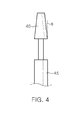
Fig. 4 is a view of a modified example of a core shown inFig. 3 . -
Fig. 5 is a constructional view (front view) of an apparatus for manufacturing a compressed scrap according to another embodiment of the present invention. -
Fig. 6 is a view of a modified example of a core shown inFig. 5 . -
Fig. 7 is a view (plan view) of the apparatus ofFig. 5 , wherein a fixing unit for a compressed scrap is further provided therein. -
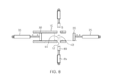
Fig. 8 is a constructional view (plan view) of an apparatus for manufacturing a compressed scrap according to still another embodiment of the present invention. - The present invention will now be described with reference to the accompanying drawings.
- As shown in
Fig. 1 , a compressed scrap S according to the present invention includes a rectangular (or regular) hexahedral body which is provided with a through-hole h. - The through-hole h passes through the center of the compressed scrap S.
- The through-hole h formed in the compressed scrap S reduces the weight of the compressed scrap and thus facilitates the handling and delivery of the compressed scrap.
- Particularly, when the compressed scrap is introduced into an electric furnace to be melted, the through-hole enables heat to be transferred directly throughout the inside of the compressed scrap to improve the melting behavior of the compressed scrap.
- That is, heat from a heat source is not gradually transferred from the outer surface of the compressed scrap toward the center thereof, but is transferred directly to the inside of the compressed scrap, so that the compressed scrap is melted more efficiently and quickly.
- Hence, the amount of electric power used in an electric furnace is reduced, resulting in reduced energy consumption and production cost.
- Further, with the formation of the through-hole h, when suppliers deliver a compressed scrap to electric furnace plants, wrongdoing or massaging about the weight of the compressed scrap by adding separate weights other than iron component to the compressed scrap can be prevented.
- That is, since such wrongdoing is generally carried out by deliberately adding separate weights into the center of the compressed scrap when compressing scrap, such that separate weights cannot be identified from the outside of the compressed scrap, when a through-hole has been formed through the compressed scrap, an inspector can easily inspect the inside of a product (compressed scrap) with the naked eye. Thus, the massaging of the weight by inclusion of foreign materials can be clearly prevented.
- In addition, the compressed scrap S may be provided with a plurality of through-holes h1 and h2 as shown in
Fig. 2 . - The plurality of through-holes h1 and h2 all pass through opposite faces of the compressed scrap S via the center thereof such that they are perpendicular to each other.
- When the plurality of through-holes h1 and h2 have been formed, heat transfer to the inside of the compressed scrap S is carried out more efficiently, improving the melting behavior, and it is difficult to hide separate foreign materials in the compressed scrap, clearly preventing the problem of the massaging in the weight of the compressed scrap S.
- Now a description will be made of an apparatus for manufacturing the compressed scrap S.
- As shown in
Fig. 3 , the apparatus includes ahousing 10 which defines a space for compressing scrap, asupport door 20 which is fixedly insertable into the space through an outlet (right opening in the drawing) of thehousing 10 when compressing scrap and is removable from the space through the outlet to open the outlet when completing the compressing of the scrap, acompressing plate 30 which is insertable into the space through an inlet (left opening in the drawing) of thehousing 10 to compress the scrap, which has already been supplied into the space, against the support door to form the compressed scraps, and acore 40 which is inserted into the space before the compressing of the scrap using thecompressing plate 30, to form a through-hole h in the compressed scrap S when compressing the scrap. - The
housing 10 has a hollow rectangular parallelepiped, opposite sides of which are open, wherein one side (the left side in the drawing) is used both as an inlet for scrap and an entrance for thecompressing plate 30, and another side (the right side in the drawing) is used both as an outlet for a compressed scrap S and an entrance for thesupport door 20. In addition, thehousing 10 may be separately provided on its upper surface with an opening door which is used as an inlet for scrap. - The
support door 20, thecompressing plate 30, and thecore 40 are mounted to ends of cylinder rods of hydraulic cylinders, respectively, so as to advance towards and retract from the inside of thehousing 10. - The
support door 20 and thecompressing plate 30 are composed of a thick steel plate strong enough to withstand a compressed load of the scrap, and the surfaces thereof with which the scrap comes into direct contact are thermally treated to improve the surface hardness. - The
core 40 has a cylindrical shape which is intended not to interfere with or to minimize an interruption of compressing movement of the scrap. - The compressing operation of the scrap is carried out as follows.
- First, the
support door 20 moves forward in the space of thehousing 10 and is fixedly held at a certain position. - In addition, the
core 40 is raised up completely into the space of thehousing 10 through anentrance 11 formed on a lower surface of thehousing 10, and is held in that state. - Next, scrap is introduced into the space of the housing through an inlet that is opposite the outlet or an entrance that is separately formed on the upper surface of the
housing 10, and the compressingplate 30 is moved forward in the space of thehousing 10. - Since a sectional area of the
housing 10, a position at which the compressingplate 30 is stopped relative to thesupport door 20, and the corresponding amount of input scrap have already been determined, the compressing of the scrap will be completed at a point where the compressingplate 30 will have completed its advance. Thereby, a hexahedrally compressed scrap S is formed between thesupport door 20 and the compressingplate 30 in the space of thehousing 10. That is, the compressingplate 30 presses against thesupport door 20, which is in a fixed state, in the space of the housing, so that scrap presented between the compressing plate and the support door in the space is compressed. - Here, as shown in
Fig. 1 , the through-hole h is formed in the hexahedral compressed scrap S while passing through the center thereof , by thecore 40. - After the scrap has been compressed into a compressed scrap S, the core 40 moves down and then the
support door 20 moves back to thereby open the outlet of thehousing 10. - Next, the compressing
plate 30 advances further to discharge the compressed scrap S out of the outlet. - The
housing 10 may be configured to tilt such that the level of the outlet becomes lower than that of the inlet in order to allow the compressed scrap S to be discharged out by its own weight (since this configuration may be simply established by fixing one side of thehousing 10 and inclining the other side of thehousing 10 using an actuator, ordinary persons skilled in the art can implement this configuration with ease by selectively combining conventional constructions if needed, even though it is not shown in a separate drawing). - The finished compressed scrap may be conveyed using a vehicle or a table which is prepared in front of the outlet of the housing. In the case where the table is used, the compressed scrap is loaded on the table, which is conveyed using a crane. In this case, the through-hole h formed in the compressed scrap is used as a lifting eye.
- In order to facilitate the removal of the core 40 from the compressed scrap S before the compressed scrap S is discharged out of the
housing 10, thecore 40 may have a frustoconical shape with a certain inclined angle (α). That is, the core has a diameter that decreases from a lower end thereof to an upper end thereof. - Hence, when the core escapes from the through-hole h of the compressed scrap S, friction with the surface of the compressed scrap is minimized, so that the core can be easily removed from the through-hole h of the compressed scrap.
- Further, the
core 40 may be disposed on a front surface of thesupport door 20 as shown inFig. 5 . - In this case, the core 40 moves in and out through the outlet of the
housing 10, together with thesupport door 20, so that thehousing 10 need not have aseparate entrance 11 as shown inFig. 3 on its lower side. Here, a separate hydraulic cylinder for actuating thecore 40 is not also required. - In this configuration, the
support door 20 and the core 40 are first inserted into the space of thehousing 10 and are held at a predefined position, then scrap is introduced into the space of thehousing 10, and the compressingplate 30 is moved forward to compress the scrap into a compressed scrap S. - Here, although a through-hole h is horizontally formed in the compressed scrap S, the direction of the through-hole h formed is not significant because the compressed scrap is of a hexahedral shape. That is, the compressed scrap S is of the same shape as those of the compressed scrap manufactured by the construction shown in
Fig. 3 . - On the one hand, also in an embodiment of
Fig. 5 , the core 40 preferably has a diameter that reduces from the rear portion to the front portion. - Such a shape may be a conical shape, for example.
- Hence, after the scrap has completely been compressed, when the
support door 20 is moved back, thecore 40 is smoothly removed from the compressed scrap S. - Then, when the compressing
plate 30 is further moved forward to push the compressed scrap S, the compressed scrap S is discharged from the housing. - An apparatus shown in
Fig. 7 is a construction that prepares the case where in the embodiment ofFig. 5 , even though thecore 40 is formed like a conical shape, thecore 40 is not removed from the compressed scrap S, so the compressed scrap S is discharged in a state where it is combined with thecore 40. - The embodiment of
Fig. 7 is characterized in that it further includes a fixing unit for the compressed scrap as compared to the embodiment ofFig. 5 . - The fixing unit includes a pair of
pressing plates 50 which press against the opposite surfaces of the compressed scrap S combined with thecore 40, and a pair ofhydraulic cylinders 55 which reciprocates thepressing plates 50, respectively. - The
pressing plate 50 may be provided on its leading surface with a plurality of pointed protrusions to increase the fixing force for the compressed scrap S. - The pressing plates of the fixing unit are disposed on opposite sides of the housing such that they face each other, and are operated at the same time.
- That is, when the compressed scrap S combined with the
core 40 has been discharged, the opposite pressing plates are then moved forward each other to firmly grip the compressed scrap S. Subsequently, thesupport door 20 and the core 40 are further moved back, thereby separating the compressed scrap S and the core 40 from each other. - Then, the
pressing plates 50 are moved back to their original positions, and as described before, the compressed scrap S is delivered. - An apparatus of
Fig. 8 is a construction that manufactures the compressed scrap S shown inFig. 2 in which through-holes h1 and h2 that intersect with each other are formed. -
Fig. 8 is a plan view of the apparatus (however, a housing is shown in section) which includes a core 40 which is disposed under thehousing 10 such that it moves up and down as shown inFig. 3 . Here, the core 40 accesses to the inside of thehousing 10 through anentrance 11 formed on a lower surface of thehousing 10. - Cross-cores 60 in pair are disposed at a position lying on the same line with the
core 40, on the outside of opposite housing walls. The cross-cores 60 are also mounted to the cylinder rods of thehydraulic cylinders 65, respectively. The cross-cores 60 may access to the inside of thehousing 10 through anentrance 12 formed on the opposite housing walls. - Particularly, the leading surfaces (facing each other) of the cross-cores 60 are concavely formed to have the same curvature as a circumference of the core 40 such that they surround and come into close contact with opposite surfaces of the circumference of the core 40 which is mounted below the housing.
- Hence, when the
core 40 is moved up into the space of the housing and the opposite cross-cores 60 are moved forward each other toward thecore 40, the cross-cores 60 perpendicularly meet the core 40 to form a cross line, thereby forming intersecting through-holes h1 and h2 in the compressed scrap S. - The effect of forming the intersecting through-holes h1 and h2 in the compressed scrap S has been described in respect of
Fig. 2 , so a repeated description thereof is omitted.
Claims (12)
- A compressed scrap having a hexahedral compressed body, wherein the hexahedral compressed body comprises a first through-hole that passes through a first pair of opposite faces thereof.
- The compressed scrap as set forth in claim 1, wherein the hexahedral compressed body is formed in the shape of a rectangular prism or a cube.
- The compressed scrap as set forth in claim 1, wherein the hexahedral compressed body comprises a second through-hole that passes through a second pair of opposite faces thereof, wherein the first through-hole and the second through-hole are perpendicular to each other and they each pass through the center of the compressed scrap.
- An apparatus for manufacturing a compressed scrap, comprising:a housing defining a space for compressing a scrap supplied therein;a support door that can be inserted into the space through an outlet of the housing and can be removed from the space through the outlet such that the outlet is opened;a compressing plate that can be inserted into the space through an inlet of the housing such that the scrap is compressed by the support door and the compressing plate; anda core that can be inserted into the space before the scrap is compressed to form a through-hole in the scrap.
- The apparatus as set forth in claim 4, wherein the core is disposed under the housing such that the core vertically reciprocates through an opening formed through a lower surface of the housing.
- The apparatus as set forth in claim 4, wherein the core is attached to a front surface of the support door.
- The apparatus as set forth in claim 4, wherein the core is of a cylindrical or conical shape.
- The apparatus as set forth in claim 4, wherein the core has a sectional area decreasing toward s end thereof.
- The apparatus as set forth in claim 4, wherein a pair of pressing plates is disposed to face each other near the outlet of the housing to press and fix the compressed scrap discharged from the outlet of the housing.
- The apparatus as set forth in claims 5 or 6, wherein a pair of cross-cores is disposed outside of opposite housing walls such that the cross-cores can approach each other to come into contact with opposite side surfaces of the core having been inserted into the space.
- The apparatus as set forth in claim 4, wherein the compressing plate is configured to advance toward the compressed scrap so as to discharge the compressed scrap out of the housing through the outlet thereof.
- The apparatus as set forth in claim 4, wherein the housing is configured to tilt toward the outlet thereof so as to discharge the compressed scrap out of the housing through the outlet thereof.
Applications Claiming Priority (2)
| Application Number | Priority Date | Filing Date | Title |
|---|---|---|---|
| KR1020100105295A KR101205148B1 (en) | 2010-10-27 | 2010-10-27 | manufacturing apparatus for compressed scrap |
| PCT/KR2011/006424 WO2012057447A2 (en) | 2010-10-27 | 2011-08-30 | Scrap compactor and apparatus for manufacturing same |
Publications (1)
| Publication Number | Publication Date |
|---|---|
| EP2633989A2 true EP2633989A2 (en) | 2013-09-04 |
Family
ID=45994498
Family Applications (1)
| Application Number | Title | Priority Date | Filing Date |
|---|---|---|---|
| EP11836539.4A Withdrawn EP2633989A2 (en) | 2010-10-27 | 2011-08-30 | Scrap compactor and apparatus for manufacturing same |
Country Status (6)
| Country | Link |
|---|---|
| US (1) | US9375891B2 (en) |
| EP (1) | EP2633989A2 (en) |
| JP (1) | JP5710773B2 (en) |
| KR (1) | KR101205148B1 (en) |
| CN (1) | CN103328196B (en) |
| WO (1) | WO2012057447A2 (en) |
Families Citing this family (4)
| Publication number | Priority date | Publication date | Assignee | Title |
|---|---|---|---|---|
| KR101327213B1 (en) * | 2012-06-11 | 2013-11-11 | 이태호 | Perforated metal scrap compressed lump release apparatus |
| KR101924785B1 (en) | 2017-07-19 | 2018-12-04 | 이유기 | Hyphenation donut-type compressors |
| KR101844194B1 (en) * | 2017-11-13 | 2018-03-30 | 주식회사 금강테크놀러지 | Waste powder forming apparatus |
| KR102521071B1 (en) * | 2021-04-08 | 2023-04-12 | 장일산업(주) | System for manufacturing of Steelmaking raw material |
Family Cites Families (15)
| Publication number | Priority date | Publication date | Assignee | Title |
|---|---|---|---|---|
| US3386374A (en) * | 1966-09-02 | 1968-06-04 | Tezuka Kunitoshi | Scrap-metal compressor |
| GB1217878A (en) * | 1967-10-03 | 1970-12-31 | Giovanni Busi | Horizontal press |
| JPS503028B1 (en) * | 1969-07-03 | 1975-01-30 | ||
| JPS5229966B2 (en) | 1973-05-14 | 1977-08-05 | ||
| JPS5353167A (en) * | 1976-10-26 | 1978-05-15 | Topii Jitsugiyou Kk | Press formation method and apparatus for metallic scrap |
| US4103610A (en) * | 1976-11-22 | 1978-08-01 | Luciano Vezzani | Metal scrap compacting press |
| JPS5398170A (en) * | 1977-02-08 | 1978-08-28 | Topii Jitsugiyou Kk | Presssforming method and apparatus for metal scraps |
| JPH0636076B2 (en) * | 1985-04-12 | 1994-05-11 | 株式会社日立製作所 | Radioactive waste granulator |
| JPH02165899A (en) | 1988-12-19 | 1990-06-26 | Fuji Car Mfg Co Ltd | Scrap compressing device |
| JP3308694B2 (en) | 1994-01-28 | 2002-07-29 | 本田技研工業株式会社 | Scrap press equipment |
| KR100235540B1 (en) * | 1997-04-21 | 1999-12-15 | 백충기 | Scrap iron crimping device |
| JP2005014072A (en) * | 2003-06-27 | 2005-01-20 | Mori Tekko Kk | Apparatus for manufacturing grinding sludge briquette |
| KR20090009739U (en) * | 2008-03-24 | 2009-09-29 | 황영규 | Scrap iron a compressor |
| CN201325190Y (en) * | 2008-12-23 | 2009-10-14 | 孙立国 | Metal particles briquetting machine of pushing material, pressing material and briquetting material by hydrocylinder |
| KR101134916B1 (en) * | 2011-01-28 | 2012-04-17 | 이태호 | Metal scrap compression material and manufacturing apparatus and manufacturing method thereof |
-
2010
- 2010-10-27 KR KR1020100105295A patent/KR101205148B1/en active Active
-
2011
- 2011-08-30 CN CN201180055131.4A patent/CN103328196B/en active Active
- 2011-08-30 JP JP2013536492A patent/JP5710773B2/en active Active
- 2011-08-30 EP EP11836539.4A patent/EP2633989A2/en not_active Withdrawn
- 2011-08-30 WO PCT/KR2011/006424 patent/WO2012057447A2/en not_active Ceased
- 2011-08-30 US US13/882,031 patent/US9375891B2/en active Active
Non-Patent Citations (1)
| Title |
|---|
| See references of WO2012057447A2 * |
Also Published As
| Publication number | Publication date |
|---|---|
| US20130220147A1 (en) | 2013-08-29 |
| US9375891B2 (en) | 2016-06-28 |
| JP2013545614A (en) | 2013-12-26 |
| KR101205148B1 (en) | 2012-11-26 |
| KR20120043973A (en) | 2012-05-07 |
| CN103328196B (en) | 2015-11-25 |
| WO2012057447A2 (en) | 2012-05-03 |
| CN103328196A (en) | 2013-09-25 |
| WO2012057447A3 (en) | 2012-06-21 |
| JP5710773B2 (en) | 2015-04-30 |
Similar Documents
| Publication | Publication Date | Title |
|---|---|---|
| US9375891B2 (en) | Scrap compactor and apparatus for manufacturing same | |
| US20120266724A1 (en) | Apparatus and method for manufacturing compressed lump of metal scrap | |
| US5669957A (en) | Dross compression apparatus and method utilizing ribs on collector and head | |
| US8661971B2 (en) | Method of manufacturing compressed lump of metal scrap | |
| CN105689685B (en) | The liquid-state forging die and method of a kind of crusher jaw | |
| JP2006104528A (en) | Steelmaking dust solidified product and method for producing the same | |
| KR101176886B1 (en) | Pressing apparatus of steel scrap | |
| CN223082832U (en) | High-efficient waste concrete component static pressure crushing equipment | |
| CN211471473U (en) | Open hearth furnace with raw material screening function for metal smelting | |
| CN112878873A (en) | Civil air defense engineering safety protection door with yaw structure and manufacturing process thereof | |
| KR101246382B1 (en) | Manufacturing method for compressed scrap | |
| Barkov et al. | Device for one-and two-sided molding of refractory metal powders into electric-arc melting electrode workpieces | |
| CN210522576U (en) | Glass crusher | |
| RU2324595C2 (en) | Device for shaping of long-length stocks out of powder materials | |
| KR102922395B1 (en) | Aluminum extrusion molding device | |
| RU2283718C2 (en) | Forging four-striker apparatus | |
| RU2289634C1 (en) | Charge materials briquetting method | |
| CN213593159U (en) | Chopping block processingequipment | |
| US6718810B1 (en) | Method and apparatus for bringing elongated metallic scrap into a more compact form | |
| RU2415730C1 (en) | Metal forming device | |
| CN111448058B (en) | Waste metal compressor | |
| CN210104640U (en) | Special cleaning tool | |
| KR100682373B1 (en) | Method and apparatus for bringing elongated metallic scrap into a more compact form | |
| KR101573213B1 (en) | A pressing apparatus of steel scrap | |
| KR20220032152A (en) | metal scrap compresses and their manufacturing devices and methods |
Legal Events
| Date | Code | Title | Description |
|---|---|---|---|
| PUAI | Public reference made under article 153(3) epc to a published international application that has entered the european phase |
Free format text: ORIGINAL CODE: 0009012 |
|
| 17P | Request for examination filed |
Effective date: 20130527 |
|
| AK | Designated contracting states |
Kind code of ref document: A2 Designated state(s): AL AT BE BG CH CY CZ DE DK EE ES FI FR GB GR HR HU IE IS IT LI LT LU LV MC MK MT NL NO PL PT RO RS SE SI SK SM TR |
|
| RIN1 | Information on inventor provided before grant (corrected) |
Inventor name: KI, JOON-SEONG |
|
| DAX | Request for extension of the european patent (deleted) | ||
| STAA | Information on the status of an ep patent application or granted ep patent |
Free format text: STATUS: THE APPLICATION HAS BEEN WITHDRAWN |
|
| 18W | Application withdrawn |
Effective date: 20170216 |