EP2633805B1 - Object information acquiring apparatus - Google Patents
Object information acquiring apparatus Download PDFInfo
- Publication number
- EP2633805B1 EP2633805B1 EP13001022.6A EP13001022A EP2633805B1 EP 2633805 B1 EP2633805 B1 EP 2633805B1 EP 13001022 A EP13001022 A EP 13001022A EP 2633805 B1 EP2633805 B1 EP 2633805B1
- Authority
- EP
- European Patent Office
- Prior art keywords
- light
- holding plate
- supporting unit
- probe
- acoustic wave
- Prior art date
- Legal status (The legal status is an assumption and is not a legal conclusion. Google has not performed a legal analysis and makes no representation as to the accuracy of the status listed.)
- Not-in-force
Links
- 239000000523 sample Substances 0.000 claims description 68
- 210000000481 breast Anatomy 0.000 claims description 14
- 238000012545 processing Methods 0.000 claims description 8
- 210000000779 thoracic wall Anatomy 0.000 claims description 3
- PCHJSUWPFVWCPO-UHFFFAOYSA-N gold Chemical compound [Au] PCHJSUWPFVWCPO-UHFFFAOYSA-N 0.000 description 25
- 239000010931 gold Substances 0.000 description 25
- 229910052737 gold Inorganic materials 0.000 description 25
- 239000006096 absorbing agent Substances 0.000 description 19
- 238000010586 diagram Methods 0.000 description 13
- 238000003384 imaging method Methods 0.000 description 9
- 230000003287 optical effect Effects 0.000 description 9
- 238000010521 absorption reaction Methods 0.000 description 8
- 238000010895 photoacoustic effect Methods 0.000 description 7
- UONOETXJSWQNOL-UHFFFAOYSA-N tungsten carbide Chemical compound [W+]#[C-] UONOETXJSWQNOL-UHFFFAOYSA-N 0.000 description 7
- 230000005540 biological transmission Effects 0.000 description 6
- 239000003795 chemical substances by application Substances 0.000 description 6
- 238000005286 illumination Methods 0.000 description 6
- 239000000463 material Substances 0.000 description 6
- 238000002834 transmittance Methods 0.000 description 6
- 238000002604 ultrasonography Methods 0.000 description 6
- 210000004204 blood vessel Anatomy 0.000 description 4
- 238000003745 diagnosis Methods 0.000 description 4
- HFGPZNIAWCZYJU-UHFFFAOYSA-N lead zirconate titanate Chemical compound [O-2].[O-2].[O-2].[O-2].[O-2].[Ti+4].[Zr+4].[Pb+2] HFGPZNIAWCZYJU-UHFFFAOYSA-N 0.000 description 4
- 229910052451 lead zirconate titanate Inorganic materials 0.000 description 4
- 238000005259 measurement Methods 0.000 description 4
- 229920000306 polymethylpentene Polymers 0.000 description 4
- 239000011116 polymethylpentene Substances 0.000 description 4
- 102000001554 Hemoglobins Human genes 0.000 description 3
- 108010054147 Hemoglobins Proteins 0.000 description 3
- NIXOWILDQLNWCW-UHFFFAOYSA-N acrylic acid group Chemical group C(C=C)(=O)O NIXOWILDQLNWCW-UHFFFAOYSA-N 0.000 description 3
- 239000004359 castor oil Substances 0.000 description 3
- 235000019438 castor oil Nutrition 0.000 description 3
- 230000007423 decrease Effects 0.000 description 3
- 239000000835 fiber Substances 0.000 description 3
- ZEMPKEQAKRGZGQ-XOQCFJPHSA-N glycerol triricinoleate Natural products CCCCCC[C@@H](O)CC=CCCCCCCCC(=O)OC[C@@H](COC(=O)CCCCCCCC=CC[C@@H](O)CCCCCC)OC(=O)CCCCCCCC=CC[C@H](O)CCCCCC ZEMPKEQAKRGZGQ-XOQCFJPHSA-N 0.000 description 3
- 229910052751 metal Inorganic materials 0.000 description 3
- 239000002184 metal Substances 0.000 description 3
- 230000000644 propagated effect Effects 0.000 description 3
- 238000012552 review Methods 0.000 description 3
- 239000000126 substance Substances 0.000 description 3
- XEEYBQQBJWHFJM-UHFFFAOYSA-N Iron Chemical compound [Fe] XEEYBQQBJWHFJM-UHFFFAOYSA-N 0.000 description 2
- 241001465754 Metazoa Species 0.000 description 2
- 230000003321 amplification Effects 0.000 description 2
- 238000006243 chemical reaction Methods 0.000 description 2
- 238000003199 nucleic acid amplification method Methods 0.000 description 2
- XLYOFNOQVPJJNP-UHFFFAOYSA-N water Substances O XLYOFNOQVPJJNP-UHFFFAOYSA-N 0.000 description 2
- VYZAMTAEIAYCRO-UHFFFAOYSA-N Chromium Chemical compound [Cr] VYZAMTAEIAYCRO-UHFFFAOYSA-N 0.000 description 1
- RTAQQCXQSZGOHL-UHFFFAOYSA-N Titanium Chemical compound [Ti] RTAQQCXQSZGOHL-UHFFFAOYSA-N 0.000 description 1
- 239000000853 adhesive Substances 0.000 description 1
- 230000001070 adhesive effect Effects 0.000 description 1
- 229910052782 aluminium Inorganic materials 0.000 description 1
- XAGFODPZIPBFFR-UHFFFAOYSA-N aluminium Chemical compound [Al] XAGFODPZIPBFFR-UHFFFAOYSA-N 0.000 description 1
- 238000000149 argon plasma sintering Methods 0.000 description 1
- QVGXLLKOCUKJST-UHFFFAOYSA-N atomic oxygen Chemical compound [O] QVGXLLKOCUKJST-UHFFFAOYSA-N 0.000 description 1
- 230000002238 attenuated effect Effects 0.000 description 1
- 238000012984 biological imaging Methods 0.000 description 1
- 239000008280 blood Substances 0.000 description 1
- 210000004369 blood Anatomy 0.000 description 1
- 201000011510 cancer Diseases 0.000 description 1
- 239000000919 ceramic Substances 0.000 description 1
- 230000008859 change Effects 0.000 description 1
- 238000009792 diffusion process Methods 0.000 description 1
- 239000007789 gas Substances 0.000 description 1
- 239000011521 glass Substances 0.000 description 1
- 229910052742 iron Inorganic materials 0.000 description 1
- 230000001678 irradiating effect Effects 0.000 description 1
- 239000007788 liquid Substances 0.000 description 1
- 230000007246 mechanism Effects 0.000 description 1
- 238000000034 method Methods 0.000 description 1
- 238000012986 modification Methods 0.000 description 1
- 230000004048 modification Effects 0.000 description 1
- 239000013307 optical fiber Substances 0.000 description 1
- 239000001301 oxygen Substances 0.000 description 1
- 229910052760 oxygen Inorganic materials 0.000 description 1
- 239000004033 plastic Substances 0.000 description 1
- 229920006289 polycarbonate film Polymers 0.000 description 1
- 102000004169 proteins and genes Human genes 0.000 description 1
- 108090000623 proteins and genes Proteins 0.000 description 1
- 230000009467 reduction Effects 0.000 description 1
- 230000004044 response Effects 0.000 description 1
- 239000004065 semiconductor Substances 0.000 description 1
- 239000010936 titanium Substances 0.000 description 1
- 229910052719 titanium Inorganic materials 0.000 description 1
- 238000003325 tomography Methods 0.000 description 1
- 239000012780 transparent material Substances 0.000 description 1
- 208000019553 vascular disease Diseases 0.000 description 1
Images


Classifications
-
- A—HUMAN NECESSITIES
- A61—MEDICAL OR VETERINARY SCIENCE; HYGIENE
- A61B—DIAGNOSIS; SURGERY; IDENTIFICATION
- A61B5/00—Measuring for diagnostic purposes; Identification of persons
- A61B5/0093—Detecting, measuring or recording by applying one single type of energy and measuring its conversion into another type of energy
- A61B5/0095—Detecting, measuring or recording by applying one single type of energy and measuring its conversion into another type of energy by applying light and detecting acoustic waves, i.e. photoacoustic measurements
-
- A—HUMAN NECESSITIES
- A61—MEDICAL OR VETERINARY SCIENCE; HYGIENE
- A61B—DIAGNOSIS; SURGERY; IDENTIFICATION
- A61B5/00—Measuring for diagnostic purposes; Identification of persons
- A61B5/70—Means for positioning the patient in relation to the detecting, measuring or recording means
- A61B5/708—Breast positioning means
-
- A—HUMAN NECESSITIES
- A61—MEDICAL OR VETERINARY SCIENCE; HYGIENE
- A61B—DIAGNOSIS; SURGERY; IDENTIFICATION
- A61B8/00—Diagnosis using ultrasonic, sonic or infrasonic waves
- A61B8/08—Detecting organic movements or changes, e.g. tumours, cysts, swellings
- A61B8/0825—Detecting organic movements or changes, e.g. tumours, cysts, swellings for diagnosis of the breast, e.g. mammography
-
- A—HUMAN NECESSITIES
- A61—MEDICAL OR VETERINARY SCIENCE; HYGIENE
- A61B—DIAGNOSIS; SURGERY; IDENTIFICATION
- A61B8/00—Diagnosis using ultrasonic, sonic or infrasonic waves
- A61B8/40—Positioning of patients, e.g. means for holding or immobilising parts of the patient's body
- A61B8/406—Positioning of patients, e.g. means for holding or immobilising parts of the patient's body using means for diagnosing suspended breasts
Definitions
- the present invention relates to an object information acquiring apparatus.
- Non Patent Literature 1 M. Xu, L. Wang "Photoacoustic imaging in biomedicine", Review of scientific instruments, 77, 041101(2006 )
- PAT photoacoustic tomography
- a light absorber included in the living organism absorbs the propagated light and generates an acoustic wave (typically, an ultrasound wave).
- An absorption coefficient distribution can be obtained by taking into account a distribution of the light with respect to the initial sound pressure distribution.
- the sound pressure of the acoustic wave in the PAT is proportional to an amount of local light that reaches the light absorber.
- the light irradiated on the living organism suddenly attenuates in the living organism because of the scattering and the absorption. Therefore, the sound pressure of the acoustic wave generated in a deep tissue in the living organism substantially attenuates according to the distance from the light irradiated region. Therefore, in order to obtain information concerning a living organism deep part, it is necessary to reduce the thickness of an object region.
- Non Patent Literature 2 “First clinical trials of the Twente Photoacoustic Mammoscope (PAM)" (Non Patent Literature 2), an object is held and pressured by two holding plates to reduce the thickness of the object.
- the holding plates are used, in order to suppress deformation due to the pressuring, in general, a supporting unit with high rigidity made of metal, ceramic, or the like is provided around the holding plates.
- a photoacoustic signal acquiring apparatus when direct light from a light source or light propagated in the living organism is irradiated on a probe surface, an acoustic wave is generated on the probe surface and the acoustic wave causes a noise.
- the acoustic wave generated on the probe surface is received by the probe first.
- An acoustic wave from the living organism is received by the probe before a response to a signal of the received acoustic wave ends.
- the signal received by the probe is a signal on which noise is superimposed.
- the photoacoustic signal acquiring apparatus when information concerning the inside of an object is converted into an image on the basis of the signal received by the probe, noise caused by an acoustic wave generated in the supporting unit is an artifact. As a result, accuracy in using the image for medical diagnosis is deteriorated.
- Patent Literature 1 discloses an example in which a light reflecting member is provided on a probe surface, whereby an acoustic wave generated on the probe surface by diffused light emitted to the outside of a living organism is reduced to reduce noise.
- Patent Literature 2 discloses a biological imaging apparatus wherein only the photo-acoustic signal radiated from a target in all directions is reflected to be collected and detected with high amplitude and resolution.
- the present invention has been devised in view of the problem and the present invention is developed to reduce, in the PAT, the noise due to the acoustic wave generated in the supporting unit that supports the holding plates.
- the present invention in its first aspect provides an object information acquiring apparatus as specified in claims 1 to 9.
- the apparatus it is possible to reduce, in the PAT, the noise due to the acoustic wave generated in the supporting unit that supports the holding plates.
- An object information acquiring apparatus is an apparatus that makes use of a photoacoustic effect for irradiating light (an electromagnetic wave) on an object to thereby receive an acoustic wave generated in the object and acquiring object information as image data.
- the object information is property information indicating a generation source distribution of the acoustic wave, an initial sound pressure distribution in the object, an optical energy absorption density distribution and an absorption coefficient distribution derived from the initial sound pressure distribution, or a concentration distribution of a substance included in a tissue.
- the concentration distribution of the substance is, for example, an oxygen saturation distribution or an oxygenated/reduced hemoglobin concentration distribution.
- the acoustic wave in the present invention is typically an ultrasound wave and includes elastic waves called a sound wave, an ultrasound wave, and an acoustic wave.
- the acoustic wave caused by the photoacoustic effect is referred to as photoacoustic wave or light-induced ultrasound wave.
- An acoustic detector e.g., a probe receives an acoustic wave generated in an object.
- the photoacoustic wave, an electric signal converted from the photoacoustic wave by the probe, or a signal obtained by applying desired signal processing such as amplification or digital conversion to the electric signal is sometimes referred to as photoacoustic signal. Therefore, the object information acquiring apparatus according to the present invention can also be grasped as a photoacoustic signal acquiring apparatus. When an acquired photoacoustic signal is converted into an image for the purpose of medical diagnosis or the like, the object information acquiring apparatus can also be grasped as a photoacoustic imaging apparatus.
- the photoacoustic signal acquiring apparatus and the photoacoustic imaging apparatus are described as examples of the object information acquiring apparatus.
- a photoacoustic signal acquiring apparatus is an apparatus that acquires information concerning the inside of an object.
- the photoacoustic signal acquiring apparatus includes, as basic hardware components, a light source, a probe that receives an acoustic wave, a holding plate that holds an object, and a supporting unit that supports the holding plate. Pulsed light emitted from the light source is irradiated on the object through the holding plate.
- Optical members such as lens, a mirror, a diffuser, and an optical fiber may be interposed between the light source and the holding plate.
- an acoustic wave (typically, an ultrasound wave) is generated by thermal expansion of the light absorber.
- the acoustic wave generated in the object is received by the probe through the holding plate.
- the light source and the probe may be present on the same side with respect to the object or may be arranged to hold the object therebetween.
- the light source irradiates light having wavelength absorbed by a specific component among components included in the living organism.
- the light source may be provided integrally with the photoacoustic signal acquiring apparatus according to this embodiment or may be provided separately from the photoacoustic signal acquiring apparatus.
- pulse width is suitable about 10 to 50 nanoseconds.
- a laser that can obtain a large output is desirable as the light source.
- a light-emitting diode, a flash lamp, or the like can also be used instead of the laser.
- various lasers such as a solid-state laser, a gas laser, a dye laser, and a semiconductor laser can be used.
- the wavelength of the light source used in the present invention is desirably wavelength that allows the light to propagate to the inside of the object. Specifically, when the object is a living organism, the wavelength is equal to or larger than 600 nm and equal to or smaller than 1100 nm.
- the object and the light absorber do not configure a part of the photoacoustic signal acquiring apparatus.
- the photoacoustic signal acquiring apparatus that makes use of the photoacoustic effect according to the present invention is used mainly for imaging of a blood vessel, diagnosis of malignant tumors, vascular diseases, and the like of a human and an animal, follow-up of a chemical treatment, and the like. Therefore, as the object, a living organism, specifically, a target region of diagnosis such as a breast, a finger, or a limb of a human body or an animal is assumed.
- the light absorber on the inside of the object relatively has a high absorption coefficient in the object depending on the wavelength of light in use. Specific examples of the light absorber include water, fat, protein, oxygenated hemoglobin, and reduced hemoglobin.
- the probe receives an acoustic wave generated on a living organism surface, inside of the living organism, and the like by pulsed light.
- the probe converts the acoustic wave into an electric signal, which is an analog signal.
- Any probe may be used as the probe as long as the probe that can receive an acoustic wave signal such as a probe that makes use of a piezoelectric phenomenon, a probe that makes use of resonance of light, or a probe that makes use of a change in capacitance.
- the probe in this embodiment is desirably a probe in which, typically, a plurality of receiving elements are one-dimensionally or two-dimensionally arranged.
- the probe When the probe is smaller than a measurement target, the probe may be scanned to receive the acoustic wave in a plurality of positions.
- the acoustic wave received by the probe is converted into an electric signal and then, after being objected to amplification, digital conversion, or the like according to necessity, used for generation of property information in a processing unit.
- a material having acoustic impedance close to the acoustic impedance of the object is used as a holding plate in order to acoustically couple the probe and the object.
- a holding plate In order to receive an acoustic wave efficiently, it is desirable to set the probe and the holding plate in contact with each other via liquid such as water, gel, or the like.
- the holding plate When light is irradiated on the object through the holding plate, the holding plate needs to be transparent to the light from the light source. Examples of the holding plate include polymethylpentene.
- the one holding plate only has to be an optically transparent material in order to transmit light. Typically, a plastic plate of acrylic or the like, a glass plate, or the like is used.
- the holding plate is supported by the supporting unit explained below.
- the holding plate includes a first joining region.
- the holding plate is equivalent to a holding unit of the present invention.
- the supporting unit is a section for suppressing deformation of the holding plate due to a load from the object.
- the supporting unit is configured by a plate-like member, an end of which is joined to an end of the holding plate.
- the supporting unit is fixed to the holding plate by screws, an adhesive, or the like.
- the supporting unit includes a second joining region.
- the material examples include tungsten carbide having a Young's modulus about two times as large as the Young's modulus of iron.
- the holding plate In the case of an apparatus with which an examinee hangs down the breast in a prone position, the holding plate is considered to be supported by the supporting unit not to topple. At this point, the supporting unit supports the chest wall of the examinee. The supporting unit is considered to support the holding plate against stress caused when the breast is pressured to thereby prevent deformation of the holding plate.
- the chest wall is supported by the supporting unit and the holding plate is supported by the supporting unit from below to keep the position and the shape of the holding plate.
- the light reflecting member is used for suppressing light emitted to the outside of the object by light diffusion from being absorbed by the supporting unit for the holding plate.
- a light reflecting film can be provided on a contact surface of the holding plate and the supporting unit.
- a dielectric multilayer film or a metal film designed according to the wavelength of light to be irradiated can be used.
- the light reflecting member a member having reflectance higher than that of the member configuring the supporting unit is desirable. Specifically, the reflectance of the light reflecting film is desirably equal to or higher than 80% at wavelength in use.
- a light reflection film including a gold film is suitably used as the light reflection film.
- the gold film it is also possible to attach a film of chrome or titanium between the gold film and the supporting unit in order to prevent the gold film from easily peeling from the supporting unit.
- the light reflecting member may be provided over the entire surface of the supporting unit or may be provided on a joining region of the holding plate to the supporting unit or a joining region of the supporting unit to the holding plate. It is also possible to insert the light reflecting member between the holding plate and the supporting unit. It is more effective to provide the light reflecting member around a joining region of the holding plate and the supporting unit as well.
- Fig. 1 is a diagram for explaining this embodiment.
- Reference numeral 101 denotes a light source
- 102 denotes a light transmission system
- 103 denotes light
- 104 denotes an illumination optical system
- 105 denotes a holding plate.
- Reference numeral 106 denotes an object
- 107 denotes a light absorber
- 108 denotes an acoustic wave.
- Reference numeral 109 denotes a probe
- 110 denotes an acoustic matching agent
- 111 denotes a supporting unit
- 112 denotes a light reflecting member.
- reference numeral 113 denotes a first joining region in the holding plate 105 and 114 denotes a second joining region in the supporting unit 111.
- a wavelength-variable titanium-sapphire laser is used as the light source 101.
- the pulse width of the titanium-sapphire laser is 10 nanoseconds, the frequency thereof is 10 Hz, and the wavelength thereof is 797 nm.
- Light emitted from the light source 101 is transmitted by the light transmission system 102 including a bundle fiber.
- the transmitted light 103 is processed into a desired light distribution shape by the illumination optical system 104 including a lens and a mirror and irradiated on the object 106 through the holding plate 105.
- the holding plate 105 is desirably a holding plate having high transmittance to light having the wavelength of the light source and high transmittance to the acoustic wave.
- a holding plate having thickness of 7 mm made of polymethylpentene is used.
- the light 103 irradiated on the object 106 propagates while diffusing in the object 106.
- a part of the light 103 is absorbed by the light absorber 107 such as a blood vessel.
- the light absorber 107 that absorbs the light 103 generates the acoustic wave 108 according to the photoacoustic effect.
- the acoustic wave 108 propagates in the object 106.
- a part of the acoustic wave 108 is received by the probe 109.
- a piezoelectric probe made of PZT (lead zirconate titanate) is used as the probe 109.
- the acoustic matching agent 110 including castor oil is provided between the holding plate 105 and the probe 109.
- the holding plate 105 is supported by the supporting unit 111 made of tungsten carbide having thickness of 3 mm.
- the supporting unit 111 made of tungsten carbide having thickness of 3 mm.
- a part of the irradiated light 103 diffuses and propagates in the direction of the supporting unit 111 as well passing through the object 106 and causes generation of an acoustic wave due to the photoacoustic effect.
- Fig. 2A is a diagram for explaining a position where the light reflecting member 112 in this embodiment is provided.
- the holding plate 105 includes the first joining region 113 joined to the supporting unit 111.
- the supporting unit 111 includes the second joining region 114 joined to the holding plate 105.
- a gold film is vapor-deposited on the second joining region 114 as the light reflecting member 112.
- the thickness of the gold film is 2000 angstroms.
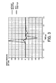
- Fig. 3 Measured values of time waveforms of acoustic waveforms generated from the supporting unit when the gold film is not affixed to the supporting unit and when the gold film is affixed to the supporting unit are shown in Fig. 3 .
- the ordinate represents sound pressure (intensity of an acoustic wave) and the abscissa represents elapsed time after light irradiation.
- the intensity of the acoustic wave is standardized by the intensity of an acoustic wave generated when the gold film is not affixed to the tungsten carbide. As it is seen from Fig.
- the light reflecting member 112 is provided on the second joining region 114.
- a place where the light reflecting member 112 is provided is not limited to this.
- the light reflecting member 112 may be provided on the first joining region 113 as shown in Fig. 2B or may be inserted between the first joining region 113 and the second joining region 114 as shown in Fig. 2C .
- the place where the light reflecting member 112 is provided can be freely determined according to, for example, easiness to provide the light reflecting member.
- the holding plate 105 having a parallel flat plate shape is described.
- the holding plate 105 is not limited to this.
- a holding plate having, for example, a bowl shape or a cylindrical shape can also be used.
- Gold is described as the light reflecting member 112.
- the light reflecting member 112 is not limited to this.
- Aluminum or the like can also be used.
- a light source and a probe are arranged on the same side with respect to a breast in a photoacoustic imaging apparatus for breast examination performed by holding the breast between two holding plates.
- the apparatus configuration in this embodiment is effective for obtaining living organism information from a region close to the probe.
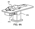
- Fig. 4A is a schematic diagram of the photoacoustic imaging apparatus.
- Fig. 4B is an apparatus configuration diagram around a breast 206, which is the object.
- Reference numeral 201 denotes a light source
- 202 denotes a light transmission system
- 203 denotes light
- 204 denotes an illumination optical system
- 205a denotes a first holding plate
- 205b denotes a second holding plate.
- Reference numeral 206 denotes an object (an examinee)
- 207 denotes a light absorber
- 208 denotes an acoustic wave
- 209 denotes a probe
- 210 denotes an acoustic matching agent.
- Reference numeral 211a denotes a first supporting unit
- 211b denotes a second supporting unit
- 212 denotes a light reflecting member
- 215 denotes a processing unit
- 216 denotes an image display unit.
- reference numeral 213 denotes a first joining region in the second holding plate 205b and 214 denotes a second joining region in the second supporting unit 211b.
- a wavelength-variable titanium-sapphire laser is used as the light source 201.
- the pulse width of the titanium-sapphire laser is 10 nanoseconds, the frequency thereof is 10 Hz, and the wavelength thereof is 797 nm.
- Light emitted from the light source 201 is transmitted by the light transmission system 202 including a bundle fiber.
- the transmitted light 203 is processed into a desired light distribution shape by the illumination optical system 204 including a lens and a mirror and irradiated on the object 206 through the second holding plate 205b.
- the second holding plate 205b is desirably a holding plate having high transmittance to light having the wavelength of the light source 201 and high transmittance to the acoustic wave 208.
- a holding plate having thickness of 7 mm made of polymethylpentene is used.
- the material and the thickness of the first holding plate 205a on the opposite side are not limited as long as the first holding plate 205a can hold the breast.
- acrylic having thickness of 10 mm is used.
- the light 203 irradiated on the object 206 propagates while diffusing in the object 206.
- a part of the light 203 is absorbed by the light absorber 207 such as a blood vessel.
- the light absorber 207 that absorbs the light 203 generates the acoustic wave 208 according to the photoacoustic effect.
- the acoustic wave 208 propagates in the object 206.
- a part of the acoustic wave 208 is received by the probe 209.
- a piezoelectric probe made of PZT is used as the probe 209.
- the acoustic matching agent 210 including castor oil is provided between the second holding plate 205b and the probe 209.
- a signal received by the probe 209 is sent to the processing unit 215, converted into image information such as an initial sound pressure distribution and an absorption coefficient distribution of the inside of the object 206, and displayed on the image display unit 216.
- This processing corresponds to generation of property information.
- the first holding plate 205a and the second holding plate 205b are respectively supported by the first supporting unit 211a and the second supporting unit 211b.
- a joining region between the first holding plate 205a and the first supporting unit 211a and a joining region between the second holding plate 205b and the second supporting unit 211b are machined in a step shape.
- Fig. 4C is a diagram showing a position where the light reflecting member 212 is provided.
- the second holding plate 205b includes the first joining region 213 joined to the second supporting unit 211b.
- the second supporting unit 211b includes the second joining region 214 joined to the second holding plate 205b.
- a gold film is vapor-deposited on the second joining region 214 as the light reflecting member 212.
- the thickness of the gold film is 2000 angstroms.
- An acoustic wave generated in the second supporting unit 211b is directly received by the probe 209. Alternatively, the acoustic wave propagates while reflecting in the second holding plate 205b to be received by the probe 209. Therefore, the influence of noise of the acoustic wave is large.
- the light reflecting member 212 is provided only between the second holding plate 205b and the second supporting unit 211b.
- a light reflecting member is not provided between the first holding plate 205a and the first supporting unit 211a.
- a light reflecting member can also be provided between the first holding plate 205a and the first supporting unit 211a.
- a light source and a probe are arranged on the opposite sides across a breast in a photoacoustic imaging apparatus for breast examination performed by holding the breast between two holding plates.
- the apparatus configuration in this embodiment is effective for obtaining living organism information from a region far from the probe.
- Fig. 5 is a diagram for explaining the third embodiment of the present invention.
- Reference numeral 301 denotes a light source
- 302 denotes a light transmission system
- 303 denotes light
- 304 denotes an illumination optical system
- 305a denotes a first holding plate
- 305b denotes a second holding plate.
- Reference numeral 306 denotes an object
- 307 denotes a light absorber
- 308 denotes an acoustic wave
- 309 denotes a probe
- 310 denotes an acoustic matching agent
- 311a denotes a first supporting unit
- 311b denotes a second supporting unit.
- Reference numeral 312a denotes a first reflecting member and 312b denotes a second light reflecting member.
- Reference numeral 315 denotes a processing unit and 316 denotes an image display unit.
- reference numeral 313a denotes a first joining region of the first holding plate 305a and reference numeral 314a denotes a second joining region of the first supporting unit 311a.
- Reference numeral 313b denotes a first joining region of the second holding plate 305b and 314b denotes a second joining region of the second supporting unit 311b.
- a wavelength-variable titanium-sapphire laser is used as the light source 301.
- the pulse width of the titanium-sapphire laser is 10 nanoseconds, the frequency thereof is 10 Hz, and the wavelength thereof is 797 nm.
- Light emitted from the light source 301 is transmitted by the light transmission system 302 including a bundle fiber.
- the transmitted light 303 is processed into a desired light distribution shape by the illumination optical system 304 including a lens and a mirror and irradiated on the object 306 through the first holding plate 305a.
- the first holding plate 305a on the light source 301 side is desirably a holding plate having high transmittance to light having the wavelength of the light source 301.
- acrylic having thickness of 10 mm is used.
- the second holding plate 305b on the probe 309 side is desirably a holding plate having high transmittance to the acoustic wave 308.
- a holding plate having thickness of 7 mm made of polymethylpentene is used.
- the light 303 irradiated on the object 306 propagates while diffusing in the object 306.
- a part of the light 303 is absorbed by the light absorber 307 such as a blood vessel.
- the light absorber 307 that absorbs the light 303 generates the acoustic wave 308 according to the photoacoustic effect.
- the acoustic wave 308 propagates in the object 306.
- a part of the acoustic wave 308 is received by the probe 309.
- a piezoelectric probe made of PZT is used as the probe 309.
- the acoustic matching agent 310 including castor oil is provided between the second holding plate 305b and the probe 309.
- a signal received by the probe 309 is sent to the processing unit 315, converted into image information such as an initial sound pressure distribution and an absorption coefficient distribution of the inside of the object 306, and displayed on the image display unit 316.
- the first holding plate 305a and the second holding plate 305b are respectively supported by the first supporting unit 311a and the second supporting unit 311b.
- a joining region between the first holding plate 305a and the first supporting unit 311a and a joining region between the second holding plate 305b and the second supporting unit 311b are machined in a step shape. Since the first supporting unit 311a is close to the light source 301, the irradiation density of light emitted from the object 306 because of scattering and irradiated in the direction of the supporting units is high and a strong acoustic wave is generated.
- the second supporting unit 311b is close to the probe 309, an acoustic wave generated in the second supporting unit 311b is received by the probe 309 before being sufficiently attenuated. Therefore, gold films are respectively provided as the first light reflecting member 312a and the second light reflecting member 312b between the first holding plate 305a and the first supporting unit 311a and between the second holding plate 305b and the second supporting unit 311b. Further, in order to suppress generation of an acoustic wave due to light directly irradiated on the supporting units not via the holding plates, a gold film is also provided on a region where the first supporting unit 311a and the second supporting unit 311b are in contact with the object 306 when the object 306 is held by the holding plates.
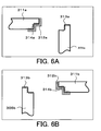
- Figs. 6A and 6B are diagrams showing, more in detail, positions where the gold films are provided.
- the first holding plate 305a includes the first joining region 313a joined to the first supporting unit 311a.
- the first supporting unit 311a includes the second joining region 314a joined to the first holding plate 305a.
- the second holding plate 305b includes the first joining region 313b joined to the second supporting unit 311b.
- the second supporting unit 311b includes the second joining region 314b joined to the second holding plate 305b.
- Both of the first light reflecting member 312a and the second light reflecting member 312b are gold films and are respectively vapor-deposited on the second joining regions 314a and 314b.
- the thickness of both the gold films is 2000 angstroms.
- the positions where the light reflecting members are provided may be on the side of the first joining regions or may be between the supporting units and the holding plates.
Description
- The present invention relates to an object information acquiring apparatus.
- As one of methods of calculating an optical property value such as an absorption coefficient in a living organism, there is photoacoustic tomography (hereinafter, PAT) that makes use of a characteristic of an ultrasound wave that scatters less in the living organism than light (Non Patent Literature 1: M. Xu, L. Wang "Photoacoustic imaging in biomedicine", Review of scientific instruments, 77, 041101(2006)). When pulsed light generated from a light source is irradiated on the living organism, the light propagates while diffusing in the living organism. A light absorber included in the living organism absorbs the propagated light and generates an acoustic wave (typically, an ultrasound wave). By receiving the acoustic wave with a probe and analyzing the received signal, it is possible to obtain an initial sound pressure distribution caused by the absorber in the living organism. An absorption coefficient distribution can be obtained by taking into account a distribution of the light with respect to the initial sound pressure distribution.
- The sound pressure of the acoustic wave in the PAT is proportional to an amount of local light that reaches the light absorber. The light irradiated on the living organism suddenly attenuates in the living organism because of the scattering and the absorption. Therefore, the sound pressure of the acoustic wave generated in a deep tissue in the living organism substantially attenuates according to the distance from the light irradiated region. Therefore, in order to obtain information concerning a living organism deep part, it is necessary to reduce the thickness of an object region. As an example, in Susanne E. et al. "First clinical trials of the Twente Photoacoustic Mammoscope (PAM)" (Non Patent Literature 2), an object is held and pressured by two holding plates to reduce the thickness of the object. When the holding plates are used, in order to suppress deformation due to the pressuring, in general, a supporting unit with high rigidity made of metal, ceramic, or the like is provided around the holding plates.
- In a photoacoustic signal acquiring apparatus, when direct light from a light source or light propagated in the living organism is irradiated on a probe surface, an acoustic wave is generated on the probe surface and the acoustic wave causes a noise. The acoustic wave generated on the probe surface is received by the probe first. An acoustic wave from the living organism is received by the probe before a response to a signal of the received acoustic wave ends. In other words, the signal received by the probe is a signal on which noise is superimposed. In the photoacoustic signal acquiring apparatus, when information concerning the inside of an object is converted into an image on the basis of the signal received by the probe, noise caused by an acoustic wave generated in the supporting unit is an artifact. As a result, accuracy in using the image for medical diagnosis is deteriorated.
- Therefore, Japanese Patent Application Laid-Open No.
2010-75681 2006-208050 -
- Patent Literature 1: Japanese Patent Application Laid-Open No.
2010-75681 - Patent Literature 2: Japanese Patent Application Laid-Open No.
2006-208050 -
- Non Patent Literature 1: M. Xu, L. Wang "Photoacoustic imaging in biomedicine", Review of scientific instruments, 77, 041101(2006)
- Non Patent Literature 2: Susanne E. et al. "First clinical trials of the Twente Photoacoustic Mammoscope(PAM)"
- However, in view of the apparatus described in M. Xu, L. Wang "Photoacoustic imaging in biomedicine", Review of scientific instruments, 77, 041101(2006), when the supporting unit that supports the holding plates is made of a material having high rigidity such as metal, an acoustic wave generated from the supporting unit by light scattering from the inside of the organism causes noise. In particular, in view of a reduction in the size of the apparatus, since the supporting unit is provided closer to the probe, the probe tends to be affected by the noise. Even if Japanese Patent Application Laid-Open No.
2010-75681 - The present invention has been devised in view of the problem and the present invention is developed to reduce, in the PAT, the noise due to the acoustic wave generated in the supporting unit that supports the holding plates.
- The present invention in its first aspect provides an object information acquiring apparatus as specified in
claims 1 to 9. - According to the apparatus, it is possible to reduce, in the PAT, the noise due to the acoustic wave generated in the supporting unit that supports the holding plates.
- Further features of the present invention will become apparent from the following description of exemplary embodiments with reference to the attached drawings.
-
-
Fig. 1 is a schematic configuration diagram showing functional blocks of an apparatus according to a first embodiment; -
Figs. 2A to 2C are diagrams for explaining positions where a light reflecting member is provided; -
Fig. 3 is a graph showing sound pressure of an acoustic wave generated in a supporting unit; -
Fig. 4A is a perspective view showing the configuration of an apparatus according to a second embodiment; -
Fig. 4B is a schematic configuration diagram showing functional blocks of the apparatus according to the second embodiment; -
Fig. 4C is a diagram showing the arrangement of a light reflecting member in the second embodiment; -
Fig. 5 is a schematic configuration diagram showing functional blocks of an apparatus according to a third embodiment; and -
Figs. 6A and 6B are diagrams showing the arrangement of a light reflecting member in the third embodiment. - Preferred embodiments of the present invention are explained below with reference to the drawings. However, dimensions, materials, and shapes of components explained below, relative arrangement of the components, and the like should be changed as appropriate according to the configuration of an apparatus to which the present invention is applied and various conditions and are not meant to limit the scope of the present invention to the below description.
- An object information acquiring apparatus according to the present invention is an apparatus that makes use of a photoacoustic effect for irradiating light (an electromagnetic wave) on an object to thereby receive an acoustic wave generated in the object and acquiring object information as image data. The object information is property information indicating a generation source distribution of the acoustic wave, an initial sound pressure distribution in the object, an optical energy absorption density distribution and an absorption coefficient distribution derived from the initial sound pressure distribution, or a concentration distribution of a substance included in a tissue. The concentration distribution of the substance is, for example, an oxygen saturation distribution or an oxygenated/reduced hemoglobin concentration distribution.
- The acoustic wave in the present invention is typically an ultrasound wave and includes elastic waves called a sound wave, an ultrasound wave, and an acoustic wave. The acoustic wave caused by the photoacoustic effect is referred to as photoacoustic wave or light-induced ultrasound wave. An acoustic detector (e.g., a probe) receives an acoustic wave generated in an object.
- The photoacoustic wave, an electric signal converted from the photoacoustic wave by the probe, or a signal obtained by applying desired signal processing such as amplification or digital conversion to the electric signal is sometimes referred to as photoacoustic signal. Therefore, the object information acquiring apparatus according to the present invention can also be grasped as a photoacoustic signal acquiring apparatus. When an acquired photoacoustic signal is converted into an image for the purpose of medical diagnosis or the like, the object information acquiring apparatus can also be grasped as a photoacoustic imaging apparatus. In the following explanation, the photoacoustic signal acquiring apparatus and the photoacoustic imaging apparatus are described as examples of the object information acquiring apparatus.
- A photoacoustic signal acquiring apparatus according to an embodiment is an apparatus that acquires information concerning the inside of an object. The photoacoustic signal acquiring apparatus according to this embodiment includes, as basic hardware components, a light source, a probe that receives an acoustic wave, a holding plate that holds an object, and a supporting unit that supports the holding plate. Pulsed light emitted from the light source is irradiated on the object through the holding plate. Optical members such as lens, a mirror, a diffuser, and an optical fiber may be interposed between the light source and the holding plate. When a part of energy of the light propagated through the inside of the object is absorbed by a light absorber (which resultantly becomes a sound source) such as blood, an acoustic wave (typically, an ultrasound wave) is generated by thermal expansion of the light absorber. The acoustic wave generated in the object is received by the probe through the holding plate. There is a degree of freedom in a positional relation between the light source and the probe. For example, the light source and the probe may be present on the same side with respect to the object or may be arranged to hold the object therebetween.
- When the object is a living organism, the light source irradiates light having wavelength absorbed by a specific component among components included in the living organism. The light source may be provided integrally with the photoacoustic signal acquiring apparatus according to this embodiment or may be provided separately from the photoacoustic signal acquiring apparatus. In order to efficiently generate an acoustic wave, pulse width is suitable about 10 to 50 nanoseconds. A laser that can obtain a large output is desirable as the light source. A light-emitting diode, a flash lamp, or the like can also be used instead of the laser. As the laser, various lasers such as a solid-state laser, a gas laser, a dye laser, and a semiconductor laser can be used. Timing, a waveform, intensity, and the like of the irradiation of the light is controlled by a not-shown light-source control unit. The light-source control unit may be integrated with the light source. The wavelength of the light source used in the present invention is desirably wavelength that allows the light to propagate to the inside of the object. Specifically, when the object is a living organism, the wavelength is equal to or larger than 600 nm and equal to or smaller than 1100 nm.
- The object and the light absorber do not configure a part of the photoacoustic signal acquiring apparatus. However, the object and the light absorber are explained below. The photoacoustic signal acquiring apparatus that makes use of the photoacoustic effect according to the present invention is used mainly for imaging of a blood vessel, diagnosis of malignant tumors, vascular diseases, and the like of a human and an animal, follow-up of a chemical treatment, and the like. Therefore, as the object, a living organism, specifically, a target region of diagnosis such as a breast, a finger, or a limb of a human body or an animal is assumed. The light absorber on the inside of the object relatively has a high absorption coefficient in the object depending on the wavelength of light in use. Specific examples of the light absorber include water, fat, protein, oxygenated hemoglobin, and reduced hemoglobin.
- The probe receives an acoustic wave generated on a living organism surface, inside of the living organism, and the like by pulsed light. The probe converts the acoustic wave into an electric signal, which is an analog signal. Any probe may be used as the probe as long as the probe that can receive an acoustic wave signal such as a probe that makes use of a piezoelectric phenomenon, a probe that makes use of resonance of light, or a probe that makes use of a change in capacitance. The probe in this embodiment is desirably a probe in which, typically, a plurality of receiving elements are one-dimensionally or two-dimensionally arranged. By using such multi-dimensionally arrayed elements, it is possible to simultaneously receive an acoustic wave in a plurality of places and reduce a measurement time. When the probe is smaller than a measurement target, the probe may be scanned to receive the acoustic wave in a plurality of positions. The acoustic wave received by the probe is converted into an electric signal and then, after being objected to amplification, digital conversion, or the like according to necessity, used for generation of property information in a processing unit.
- A material having acoustic impedance close to the acoustic impedance of the object is used as a holding plate in order to acoustically couple the probe and the object. In order to receive an acoustic wave efficiently, it is desirable to set the probe and the holding plate in contact with each other via liquid such as water, gel, or the like. When light is irradiated on the object through the holding plate, the holding plate needs to be transparent to the light from the light source. Examples of the holding plate include polymethylpentene. When the object is held by two holding plates and light is irradiated on the surface of the object on the opposite side of the probe, the acoustic impedance of one holding plate does not have to be taken into account. The one holding plate only has to be an optically transparent material in order to transmit light. Typically, a plastic plate of acrylic or the like, a glass plate, or the like is used. The holding plate is supported by the supporting unit explained below. The holding plate includes a first joining region. The holding plate is equivalent to a holding unit of the present invention.
- The supporting unit is a section for suppressing deformation of the holding plate due to a load from the object. Typically, the supporting unit is configured by a plate-like member, an end of which is joined to an end of the holding plate. The supporting unit is fixed to the holding plate by screws, an adhesive, or the like. The supporting unit includes a second joining region. When the supporting unit is present within a view angle of the probe, a dead space in which photoacoustic signal measurement cannot be performed is formed. Therefore, it is desirable to reduce the thickness of the supporting unit as much as possible in order to reduce the dead space. Therefore, a material having a large Young's modulus is desirable. Examples of the material include tungsten carbide having a Young's modulus about two times as large as the Young's modulus of iron. In the case of an apparatus with which an examinee hangs down the breast in a prone position, the holding plate is considered to be supported by the supporting unit not to topple. At this point, the supporting unit supports the chest wall of the examinee. The supporting unit is considered to support the holding plate against stress caused when the breast is pressured to thereby prevent deformation of the holding plate. In the case of an apparatus with which the examinee places the breast on the holding plate in an upright position, the chest wall is supported by the supporting unit and the holding plate is supported by the supporting unit from below to keep the position and the shape of the holding plate.
- The light reflecting member is used for suppressing light emitted to the outside of the object by light diffusion from being absorbed by the supporting unit for the holding plate. For example, a light reflecting film can be provided on a contact surface of the holding plate and the supporting unit. As the light reflecting film, a dielectric multilayer film or a metal film designed according to the wavelength of light to be irradiated can be used. As the light reflecting member, a member having reflectance higher than that of the member configuring the supporting unit is desirable. Specifically, the reflectance of the light reflecting film is desirably equal to or higher than 80% at wavelength in use. For example, when light in a range of wavelength equal to or longer than 600 nm and equal to or shorter than 1100 nm is used as irradiation light, a light reflection film including a gold film is suitably used as the light reflection film. When the gold film is used, it is also possible to attach a film of chrome or titanium between the gold film and the supporting unit in order to prevent the gold film from easily peeling from the supporting unit. The light reflecting member may be provided over the entire surface of the supporting unit or may be provided on a joining region of the holding plate to the supporting unit or a joining region of the supporting unit to the holding plate. It is also possible to insert the light reflecting member between the holding plate and the supporting unit. It is more effective to provide the light reflecting member around a joining region of the holding plate and the supporting unit as well.
- In a first embodiment, an example in which an object is held to be pressed against a holding plate is explained.
Fig. 1 is a diagram for explaining this embodiment.Reference numeral 101 denotes a light source, 102 denotes a light transmission system, 103 denotes light, 104 denotes an illumination optical system, and 105 denotes a holding plate.Reference numeral 106 denotes an object, 107 denotes a light absorber, and 108 denotes an acoustic wave.Reference numeral 109 denotes a probe, 110 denotes an acoustic matching agent, 111 denotes a supporting unit, and 112 denotes a light reflecting member. InFigs. 2A to 2C ,reference numeral 113 denotes a first joining region in the holdingplate unit 111. - In this embodiment, a wavelength-variable titanium-sapphire laser is used as the
light source 101. The pulse width of the titanium-sapphire laser is 10 nanoseconds, the frequency thereof is 10 Hz, and the wavelength thereof is 797 nm. Light emitted from thelight source 101 is transmitted by thelight transmission system 102 including a bundle fiber. The transmittedlight 103 is processed into a desired light distribution shape by the illuminationoptical system 104 including a lens and a mirror and irradiated on theobject 106 through the holdingplate 105. In order to efficiently receive the acoustic wave from the object, the holdingplate 105 is desirably a holding plate having high transmittance to light having the wavelength of the light source and high transmittance to the acoustic wave. In this embodiment, a holding plate having thickness of 7 mm made of polymethylpentene is used. - The light 103 irradiated on the
object 106 propagates while diffusing in theobject 106. A part of the light 103 is absorbed by thelight absorber 107 such as a blood vessel. Thelight absorber 107 that absorbs the light 103 generates theacoustic wave 108 according to the photoacoustic effect. Theacoustic wave 108 propagates in theobject 106. A part of theacoustic wave 108 is received by theprobe 109. As theprobe 109, a piezoelectric probe made of PZT (lead zirconate titanate) is used. In order to realize acoustic matching of the holdingplate 105 and theprobe 109, theacoustic matching agent 110 including castor oil is provided between the holdingplate 105 and theprobe 109. The holdingplate 105 is supported by the supportingunit 111 made of tungsten carbide having thickness of 3 mm. As shown in the figure, a part of theirradiated light 103 diffuses and propagates in the direction of the supportingunit 111 as well passing through theobject 106 and causes generation of an acoustic wave due to the photoacoustic effect. - A position where the
light reflecting member 112, which is a characteristic of the present invention, is explained with reference toFigs. 2A to 2C. Fig. 2A is a diagram for explaining a position where thelight reflecting member 112 in this embodiment is provided. The holdingplate 105 includes the first joiningregion 113 joined to the supportingunit 111. The supportingunit 111 includes the second joiningregion 114 joined to the holdingplate 105. In this embodiment, a gold film is vapor-deposited on the second joiningregion 114 as thelight reflecting member 112. The thickness of the gold film is 2000 angstroms. When the reflectance of the gold film was measured, the reflectance was 88% of the reflectance of light having wavelength of 797 nm made perpendicularly incident on the gold film. The reflectance of tungsten carbide not affixed with the gold film was 20% of the light having wavelength of 797 nm made perpendicularly incident on the tungsten carbide. - Measured values of time waveforms of acoustic waveforms generated from the supporting unit when the gold film is not affixed to the supporting unit and when the gold film is affixed to the supporting unit are shown in
Fig. 3 . The ordinate represents sound pressure (intensity of an acoustic wave) and the abscissa represents elapsed time after light irradiation. The intensity of the acoustic wave is standardized by the intensity of an acoustic wave generated when the gold film is not affixed to the tungsten carbide. As it is seen fromFig. 3 , by affixing the gold film to the tungsten carbide, compared with the intensity of the acoustic wave generated when the gold film is not affixed, the intensity of the acoustic wave generated from the tungsten carbide is reduced to 12%. This result indicates that noise deriving from the acoustic wave generated in the supporting unit is reduced and it is possible to accurately measure, with the probe, an acoustic wave signal generated in the object. In this way, it is possible to perform highly accurate photoacoustic signal measurement by providing the light reflecting member on the surface of the supporting unit. - In this embodiment, the
light reflecting member 112 is provided on the second joiningregion 114. However, a place where thelight reflecting member 112 is provided is not limited to this. Specifically, thelight reflecting member 112 may be provided on the first joiningregion 113 as shown inFig. 2B or may be inserted between the first joiningregion 113 and the second joiningregion 114 as shown inFig. 2C . The place where thelight reflecting member 112 is provided can be freely determined according to, for example, easiness to provide the light reflecting member. When thelight reflecting member 112 is inserted between the first joiningregion 113 and the second joiningregion 114, for example, it is suitable to use a polycarbonate film affixed with the gold film. It is effective to provide thelight reflecting member 112 around a joining region of the holdingplate 105 and the supportingunit 111 as well because the generation of an acoustic wave due to light that scatters in theobject 106 and reaches the joining region is further suppressed. Irrespective of where thelight reflecting member 112 is provided, it is possible to fix thelight reflecting member 112 by joining the end of the holdingplate 105 and the supportingunit 111. It is also possible to guide the breast of an examinee, which is theobject 106, to the holdingplate 105. - In this embodiment, the holding
plate 105 having a parallel flat plate shape is described. However, the holdingplate 105 is not limited to this. A holding plate having, for example, a bowl shape or a cylindrical shape can also be used. Gold is described as thelight reflecting member 112. However, thelight reflecting member 112 is not limited to this. Aluminum or the like can also be used. - In a second embodiment, an example in which a light source and a probe are arranged on the same side with respect to a breast in a photoacoustic imaging apparatus for breast examination performed by holding the breast between two holding plates is explained. The apparatus configuration in this embodiment is effective for obtaining living organism information from a region close to the probe.
-
Fig. 4A is a schematic diagram of the photoacoustic imaging apparatus.Fig. 4B is an apparatus configuration diagram around abreast 206, which is the object.Reference numeral 201 denotes a light source, 202 denotes a light transmission system, 203 denotes light, 204 denotes an illumination optical system, 205a denotes a first holding plate, and 205b denotes a second holding plate.Reference numeral 206 denotes an object (an examinee), 207 denotes a light absorber, 208 denotes an acoustic wave, 209 denotes a probe, and 210 denotes an acoustic matching agent.Reference numeral 211a denotes a first supporting unit, 211b denotes a second supporting unit, 212 denotes a light reflecting member, 215 denotes a processing unit, and 216 denotes an image display unit. InFig. 4C ,reference numeral 213 denotes a first joining region in thesecond holding plate unit 211b. - In this embodiment, a wavelength-variable titanium-sapphire laser is used as the
light source 201. The pulse width of the titanium-sapphire laser is 10 nanoseconds, the frequency thereof is 10 Hz, and the wavelength thereof is 797 nm. Light emitted from thelight source 201 is transmitted by thelight transmission system 202 including a bundle fiber. The transmittedlight 203 is processed into a desired light distribution shape by the illuminationoptical system 204 including a lens and a mirror and irradiated on theobject 206 through thesecond holding plate 205b. In order to efficiently receive the acoustic wave from theobject 206, thesecond holding plate 205b is desirably a holding plate having high transmittance to light having the wavelength of thelight source 201 and high transmittance to theacoustic wave 208. In this embodiment, a holding plate having thickness of 7 mm made of polymethylpentene is used. The material and the thickness of thefirst holding plate 205a on the opposite side are not limited as long as thefirst holding plate 205a can hold the breast. In this embodiment, acrylic having thickness of 10 mm is used. - The light 203 irradiated on the
object 206 propagates while diffusing in theobject 206. A part of the light 203 is absorbed by thelight absorber 207 such as a blood vessel. Thelight absorber 207 that absorbs the light 203 generates theacoustic wave 208 according to the photoacoustic effect. Theacoustic wave 208 propagates in theobject 206. A part of theacoustic wave 208 is received by theprobe 209. As theprobe 209, a piezoelectric probe made of PZT is used. In order to realize acoustic matching of thesecond holding plate 205b and theprobe 209, theacoustic matching agent 210 including castor oil is provided between thesecond holding plate 205b and theprobe 209. A signal received by theprobe 209 is sent to theprocessing unit 215, converted into image information such as an initial sound pressure distribution and an absorption coefficient distribution of the inside of theobject 206, and displayed on theimage display unit 216. This processing corresponds to generation of property information. Thefirst holding plate 205a and thesecond holding plate 205b are respectively supported by the first supportingunit 211a and the second supportingunit 211b. In order to bear a load due to pressuring and a load due to the weight of theobject 206, a joining region between thefirst holding plate 205a and the first supportingunit 211a and a joining region between thesecond holding plate 205b and the second supportingunit 211b are machined in a step shape. -
Fig. 4C is a diagram showing a position where thelight reflecting member 212 is provided. Thesecond holding plate 205b includes the first joiningregion 213 joined to the second supportingunit 211b. The second supportingunit 211b includes the second joiningregion 214 joined to thesecond holding plate 205b. A gold film is vapor-deposited on the second joiningregion 214 as thelight reflecting member 212. The thickness of the gold film is 2000 angstroms. An acoustic wave generated in the second supportingunit 211b is directly received by theprobe 209. Alternatively, the acoustic wave propagates while reflecting in thesecond holding plate 205b to be received by theprobe 209. Therefore, the influence of noise of the acoustic wave is large. On the other hand, since the first supportingunit 211a is far from thelight source 201 and theprobe 209, the influence of noise due to an acoustic wave generated in the first supportingunit 211a is small. Therefore, in this embodiment, thelight reflecting member 212 is provided only between thesecond holding plate 205b and the second supportingunit 211b. A light reflecting member is not provided between thefirst holding plate 205a and the first supportingunit 211a. However, a light reflecting member can also be provided between thefirst holding plate 205a and the first supportingunit 211a. - By adopting the configuration explained above, in the light 203 irradiated on the
object 206, components emitted from theobject 206 because of scattering and irradiated in the direction of the supporting units are reflected by the gold film. Then, an amount of light absorbed by the second supportingunit 211b decreases and the acoustic wave generated in the second supportingunit 211b decreases. As a result, noise deriving from the acoustic waves generated in the supporting units is reduced. It is possible to obtain a satisfactory photoacoustic image with little artifact. - In a third embodiment, an example in which a light source and a probe are arranged on the opposite sides across a breast in a photoacoustic imaging apparatus for breast examination performed by holding the breast between two holding plates is explained. The apparatus configuration in this embodiment is effective for obtaining living organism information from a region far from the probe.
-
Fig. 5 is a diagram for explaining the third embodiment of the present invention.Reference numeral 301 denotes a light source, 302 denotes a light transmission system, 303 denotes light, 304 denotes an illumination optical system, 305a denotes a first holding plate, and 305b denotes a second holding plate.Reference numeral 306 denotes an object, 307 denotes a light absorber, 308 denotes an acoustic wave, 309 denotes a probe, 310 denotes an acoustic matching agent, 311a denotes a first supporting unit, and 311b denotes a second supporting unit.Reference numeral 312a denotes a first reflecting member and 312b denotes a second light reflecting member.Reference numeral 315 denotes a processing unit and 316 denotes an image display unit. - In
Figs. 6A and 6B ,reference numeral 313a denotes a first joining region of thefirst holding plate 305a andreference numeral 314a denotes a second joining region of the first supportingunit 311a.Reference numeral 313b denotes a first joining region of thesecond holding plate unit 311b. - In this embodiment, a wavelength-variable titanium-sapphire laser is used as the
light source 301. The pulse width of the titanium-sapphire laser is 10 nanoseconds, the frequency thereof is 10 Hz, and the wavelength thereof is 797 nm. Light emitted from thelight source 301 is transmitted by thelight transmission system 302 including a bundle fiber. The transmittedlight 303 is processed into a desired light distribution shape by the illuminationoptical system 304 including a lens and a mirror and irradiated on theobject 306 through thefirst holding plate 305a. Thefirst holding plate 305a on thelight source 301 side is desirably a holding plate having high transmittance to light having the wavelength of thelight source 301. In this embodiment, acrylic having thickness of 10 mm is used. On the other hand, in order to efficiently receive theacoustic wave 308 from theobject 306, thesecond holding plate 305b on theprobe 309 side is desirably a holding plate having high transmittance to theacoustic wave 308. In this embodiment, a holding plate having thickness of 7 mm made of polymethylpentene is used. - The light 303 irradiated on the
object 306 propagates while diffusing in theobject 306. A part of the light 303 is absorbed by thelight absorber 307 such as a blood vessel. Thelight absorber 307 that absorbs the light 303 generates theacoustic wave 308 according to the photoacoustic effect. Theacoustic wave 308 propagates in theobject 306. A part of theacoustic wave 308 is received by theprobe 309. As theprobe 309, a piezoelectric probe made of PZT is used. In order to realize acoustic matching of thesecond holding plate 305b and theprobe 309, theacoustic matching agent 310 including castor oil is provided between thesecond holding plate 305b and theprobe 309. A signal received by theprobe 309 is sent to theprocessing unit 315, converted into image information such as an initial sound pressure distribution and an absorption coefficient distribution of the inside of theobject 306, and displayed on theimage display unit 316. - The
first holding plate 305a and thesecond holding plate 305b are respectively supported by the first supportingunit 311a and the second supportingunit 311b. In order to bear a load due to pressuring and a load due to the weight of theobject 306, a joining region between thefirst holding plate 305a and the first supportingunit 311a and a joining region between thesecond holding plate 305b and the second supportingunit 311b are machined in a step shape. Since the first supportingunit 311a is close to thelight source 301, the irradiation density of light emitted from theobject 306 because of scattering and irradiated in the direction of the supporting units is high and a strong acoustic wave is generated. On the other hand, since the second supportingunit 311b is close to theprobe 309, an acoustic wave generated in the second supportingunit 311b is received by theprobe 309 before being sufficiently attenuated. Therefore, gold films are respectively provided as the firstlight reflecting member 312a and the secondlight reflecting member 312b between thefirst holding plate 305a and the first supportingunit 311a and between thesecond holding plate 305b and the second supportingunit 311b. Further, in order to suppress generation of an acoustic wave due to light directly irradiated on the supporting units not via the holding plates, a gold film is also provided on a region where the first supportingunit 311a and the second supportingunit 311b are in contact with theobject 306 when theobject 306 is held by the holding plates. -
Figs. 6A and 6B are diagrams showing, more in detail, positions where the gold films are provided. Thefirst holding plate 305a includes the first joiningregion 313a joined to the first supportingunit 311a. The first supportingunit 311a includes the second joiningregion 314a joined to thefirst holding plate 305a. Thesecond holding plate 305b includes the first joiningregion 313b joined to the second supportingunit 311b. The second supportingunit 311b includes the second joiningregion 314b joined to thesecond holding plate 305b. Both of the firstlight reflecting member 312a and the secondlight reflecting member 312b are gold films and are respectively vapor-deposited on the second joiningregions - By adopting the configuration explained above, in the light 303 irradiated on the
object 306, components emitted from theobject 306 because of scattering and irradiated in the direction of the supporting units are reflected by the gold films. In this embodiment, reflectance to light directly irradiated on the supporting units from the object not via the holding plates is also improved. Therefore, an amount of light absorbed by the supporting units is smaller than the amount of the light in the second embodiment. Then, acoustic waves generated in the first supportingunit 311a and the second supportingunit 311b decrease. As a result, noise deriving from the acoustic waves generated in the supporting units is reduced. It is possible to obtain a satisfactory photoacoustic image with little artifact. - While the present invention has been described with reference to exemplary embodiments, it is to be understood that the invention is not limited to the disclosed exemplary embodiments. The scope of the following claims is to be accorded the broadest interpretation so as to encompass all such modifications and equivalent structures and functions.
Claims (9)
- An object information acquiring apparatus comprising:a light source (101);a holding plate (105) configured to hold an object (106) and being transparent to light from the light source; anda probe (109) configured to receive, via the holding plate, an acoustic wave (108) generated from the object on which light (103) is irradiated from the light source, characterized by further comprisinga supporting unit (111) configured to support the holding plate via respective joining regions (113, 114); anda light reflecting member (112) having reflectance higher than that of the supporting unit and being provided between the joining region of the supporting unit and the joining region of the holding plate.
- The object information acquiring apparatus according to claim 1, wherein the supporting unit is a plate-like member, an end of which is joined to an end of the holding plate.
- The object information acquiring apparatus according to claim 1, wherein the supporting unit is a plate-like member configured to support a chest wall of an examinee and can guide a breast of the examinee, which is the object, to the holding plate by the supporting unit being joined to an end of the holding plate at an end of the plate-like member.
- The object information acquiring apparatus according to any one of claims 1 to 3, wherein the light reflecting member is provided on the joining region of the holding plate.
- The object information acquiring apparatus according to any one of claims 1 to 3, wherein the light reflecting member is provided on the joining region of the supporting unit.
- The object information acquiring apparatus according to any one of claims 1 to 3, wherein the light reflecting member is inserted between the holding plate and the supporting unit.
- The object information acquiring apparatus according to any one of claims 1 to 6, wherein the reflecting member is provided also around the joining region of the supporting unit and the holding plate.
- The object information acquiring apparatus according to any one of claims 1 to 7, wherein the holding plate has a bowl shape or a cylindrical shape.
- The object information acquiring apparatus according to any one of claims 1 to 8, further comprising a processing unit configured to generate property information of an inside of the object on the basis of the acoustic wave.
Applications Claiming Priority (1)
| Application Number | Priority Date | Filing Date | Title |
|---|---|---|---|
| JP2012047005A JP6025345B2 (en) | 2012-03-02 | 2012-03-02 | Subject information acquisition device |
Publications (2)
| Publication Number | Publication Date |
|---|---|
| EP2633805A1 EP2633805A1 (en) | 2013-09-04 |
| EP2633805B1 true EP2633805B1 (en) | 2015-09-09 |
Family
ID=47901726
Family Applications (1)
| Application Number | Title | Priority Date | Filing Date |
|---|---|---|---|
| EP13001022.6A Not-in-force EP2633805B1 (en) | 2012-03-02 | 2013-02-28 | Object information acquiring apparatus |
Country Status (4)
| Country | Link |
|---|---|
| US (1) | US9326688B2 (en) |
| EP (1) | EP2633805B1 (en) |
| JP (1) | JP6025345B2 (en) |
| CN (1) | CN103356229B (en) |
Families Citing this family (7)
| Publication number | Priority date | Publication date | Assignee | Title |
|---|---|---|---|---|
| JP5843496B2 (en) | 2010-07-22 | 2016-01-13 | キヤノン株式会社 | Acoustic wave detector and acoustic wave measuring device |
| JP5751769B2 (en) | 2010-07-27 | 2015-07-22 | キヤノン株式会社 | Image information acquisition apparatus and control method thereof |
| JP6053339B2 (en) | 2012-06-06 | 2016-12-27 | キヤノン株式会社 | Subject information acquisition apparatus and subject information acquisition method |
| WO2015054688A2 (en) | 2013-10-11 | 2015-04-16 | Seno Medical Instruments, Inc. | Systems and methods for component separation in medical imaging |
| US9320451B2 (en) | 2014-02-27 | 2016-04-26 | Kimberly-Clark Worldwide, Inc. | Methods for assessing health conditions using single coil magnetic induction tomography imaging |
| JP6443851B2 (en) | 2014-08-04 | 2018-12-26 | キヤノン株式会社 | Subject information acquisition apparatus, subject information acquisition method, and program |
| US10499815B2 (en) * | 2014-09-05 | 2019-12-10 | Canon Kabushiki Kaisha | Object information acquiring apparatus |
Family Cites Families (22)
| Publication number | Priority date | Publication date | Assignee | Title |
|---|---|---|---|---|
| JPS58108523A (en) * | 1981-12-23 | 1983-06-28 | Toshiba Corp | Light defracting and diffusing plate device |
| US6212421B1 (en) * | 1999-09-03 | 2001-04-03 | Lockheed Martin Energy Research Corp. | Method and apparatus of spectro-acoustically enhanced ultrasonic detection for diagnostics |
| JP4220102B2 (en) | 2000-05-02 | 2009-02-04 | 富士フイルム株式会社 | Dynamic change detection method, dynamic change detection apparatus, and ultrasonic diagnostic apparatus |
| JP4643153B2 (en) * | 2004-02-06 | 2011-03-02 | 株式会社東芝 | Non-invasive biological information imaging device |
| JP4422626B2 (en) | 2005-01-25 | 2010-02-24 | 日本電信電話株式会社 | Biological imaging device |
| JP2007229320A (en) * | 2006-03-03 | 2007-09-13 | Nippon Telegr & Teleph Corp <Ntt> | Component concentration measuring apparatus |
| JP4773390B2 (en) * | 2007-03-28 | 2011-09-14 | 日本電信電話株式会社 | Component concentration measuring device |
| US20090005685A1 (en) * | 2007-06-29 | 2009-01-01 | Canon Kabushiki Kaisha | Ultrasonic probe and inspection apparatus equipped with the ultrasonic probe |
| JP2009181981A (en) * | 2008-01-29 | 2009-08-13 | Renesas Technology Corp | Manufacturing process of semiconductor device, and the semiconductor device |
| JP5210080B2 (en) * | 2008-07-31 | 2013-06-12 | 富士フイルム株式会社 | Medical imaging device |
| JP4900979B2 (en) * | 2008-08-27 | 2012-03-21 | キヤノン株式会社 | Photoacoustic apparatus and probe for receiving photoacoustic waves |
| JP5692986B2 (en) * | 2008-12-25 | 2015-04-01 | キヤノン株式会社 | Subject information acquisition device |
| JP5455006B2 (en) * | 2009-01-21 | 2014-03-26 | キヤノン株式会社 | Compression device used for ultrasonic measurement, compression control method thereof, and photoacoustic measurement device |
| JP5289073B2 (en) * | 2009-01-21 | 2013-09-11 | キヤノン株式会社 | COMPRESSION DEVICE USED FOR ULTRASONIC MEASUREMENT AND ITS COMPRESSION CONTROL METHOD, PHOTOACOUSTIC MEASUREMENT DEVICE AND ITS CONTROL METHOD |
| JP5448785B2 (en) * | 2009-12-18 | 2014-03-19 | キヤノン株式会社 | Measuring device, movement control method, and program |
| JP5441781B2 (en) * | 2010-03-25 | 2014-03-12 | キヤノン株式会社 | Photoacoustic imaging apparatus, photoacoustic imaging method, and program |
| JP5721477B2 (en) * | 2010-04-22 | 2015-05-20 | キヤノン株式会社 | measuring device |
| JP5641773B2 (en) | 2010-04-28 | 2014-12-17 | キヤノン株式会社 | measuring device |
| JP5587046B2 (en) * | 2010-06-10 | 2014-09-10 | キヤノン株式会社 | Photoacoustic measuring device |
| JP5843496B2 (en) | 2010-07-22 | 2016-01-13 | キヤノン株式会社 | Acoustic wave detector and acoustic wave measuring device |
| JP5863345B2 (en) | 2011-09-08 | 2016-02-16 | キヤノン株式会社 | Subject information acquisition apparatus and subject information acquisition method |
| JP2013150781A (en) | 2011-12-26 | 2013-08-08 | Canon Inc | Characteristic information acquisition apparatus |
-
2012
- 2012-03-02 JP JP2012047005A patent/JP6025345B2/en active Active
-
2013
- 2013-02-26 CN CN201310058955.8A patent/CN103356229B/en not_active Expired - Fee Related
- 2013-02-26 US US13/776,888 patent/US9326688B2/en active Active
- 2013-02-28 EP EP13001022.6A patent/EP2633805B1/en not_active Not-in-force
Also Published As
| Publication number | Publication date |
|---|---|
| JP2013180117A (en) | 2013-09-12 |
| JP6025345B2 (en) | 2016-11-16 |
| CN103356229B (en) | 2015-04-29 |
| US9326688B2 (en) | 2016-05-03 |
| US20130231549A1 (en) | 2013-09-05 |
| EP2633805A1 (en) | 2013-09-04 |
| CN103356229A (en) | 2013-10-23 |
Similar Documents
| Publication | Publication Date | Title |
|---|---|---|
| EP2633805B1 (en) | Object information acquiring apparatus | |
| JP5541662B2 (en) | Subject information acquisition apparatus and control method thereof | |
| EP2553425B1 (en) | Photoacoustic imaging apparatus and photoacoustic imaging method | |
| JP5751769B2 (en) | Image information acquisition apparatus and control method thereof | |
| US20100087733A1 (en) | Biological information processing apparatus and biological information processing method | |
| US9615751B2 (en) | Object information acquiring apparatus and object information acquiring method | |
| JP2013255707A (en) | Subject information acquisition apparatus and photoacoustic probe | |
| JP2010088627A5 (en) | ||
| JP5863345B2 (en) | Subject information acquisition apparatus and subject information acquisition method | |
| US20130085371A1 (en) | Acoustic wave acquiring apparatus | |
| JP2011160936A (en) | Photoacoustic image forming apparatus and photoacoustic image forming method | |
| US20130331681A1 (en) | Object information acquisition apparatus and photoacoustic probe | |
| US20130237800A1 (en) | Object information acquiring apparatus | |
| US9883807B2 (en) | Object information acquiring apparatus and control method therefor | |
| US9901257B2 (en) | Object information acquiring apparatus and photoacoustic probe | |
| JP2013188489A (en) | Subject information processing apparatus and method for operating the same | |
| JP2014046069A (en) | Test object information acquisition apparatus | |
| JP6005211B2 (en) | Image information acquisition apparatus and image information acquisition method | |
| JP6679327B2 (en) | Ultrasonic device | |
| JP2014239830A (en) | Subject information acquisition device, control method thereof, and holding device | |
| JP2014226427A (en) | Subject information acquisition apparatus and subject holding apparatus |
Legal Events
| Date | Code | Title | Description |
|---|---|---|---|
| PUAI | Public reference made under article 153(3) epc to a published international application that has entered the european phase |
Free format text: ORIGINAL CODE: 0009012 |
|
| AK | Designated contracting states |
Kind code of ref document: A1 Designated state(s): AL AT BE BG CH CY CZ DE DK EE ES FI FR GB GR HR HU IE IS IT LI LT LU LV MC MK MT NL NO PL PT RO RS SE SI SK SM TR |
|
| AX | Request for extension of the european patent |
Extension state: BA ME |
|
| 17P | Request for examination filed |
Effective date: 20140304 |
|
| RBV | Designated contracting states (corrected) |
Designated state(s): AL AT BE BG CH CY CZ DE DK EE ES FI FR GB GR HR HU IE IS IT LI LT LU LV MC MK MT NL NO PL PT RO RS SE SI SK SM TR |
|
| 17Q | First examination report despatched |
Effective date: 20140926 |
|
| GRAP | Despatch of communication of intention to grant a patent |
Free format text: ORIGINAL CODE: EPIDOSNIGR1 |
|
| INTG | Intention to grant announced |
Effective date: 20150220 |
|
| GRAS | Grant fee paid |
Free format text: ORIGINAL CODE: EPIDOSNIGR3 |
|
| RAP1 | Party data changed (applicant data changed or rights of an application transferred) |
Owner name: CANON KABUSHIKI KAISHA |
|
| GRAA | (expected) grant |
Free format text: ORIGINAL CODE: 0009210 |
|
| AK | Designated contracting states |
Kind code of ref document: B1 Designated state(s): AL AT BE BG CH CY CZ DE DK EE ES FI FR GB GR HR HU IE IS IT LI LT LU LV MC MK MT NL NO PL PT RO RS SE SI SK SM TR |
|
| REG | Reference to a national code |
Ref country code: GB Ref legal event code: FG4D |
|
| REG | Reference to a national code |
Ref country code: AT Ref legal event code: REF Ref document number: 747423 Country of ref document: AT Kind code of ref document: T Effective date: 20150915 Ref country code: CH Ref legal event code: EP |
|
| REG | Reference to a national code |
Ref country code: IE Ref legal event code: FG4D |
|
| REG | Reference to a national code |
Ref country code: DE Ref legal event code: R096 Ref document number: 602013002861 Country of ref document: DE |
|
| REG | Reference to a national code |
Ref country code: NL Ref legal event code: MP Effective date: 20150909 |
|
| PG25 | Lapsed in a contracting state [announced via postgrant information from national office to epo] |
Ref country code: LV Free format text: LAPSE BECAUSE OF FAILURE TO SUBMIT A TRANSLATION OF THE DESCRIPTION OR TO PAY THE FEE WITHIN THE PRESCRIBED TIME-LIMIT Effective date: 20150909 Ref country code: LT Free format text: LAPSE BECAUSE OF FAILURE TO SUBMIT A TRANSLATION OF THE DESCRIPTION OR TO PAY THE FEE WITHIN THE PRESCRIBED TIME-LIMIT Effective date: 20150909 Ref country code: FI Free format text: LAPSE BECAUSE OF FAILURE TO SUBMIT A TRANSLATION OF THE DESCRIPTION OR TO PAY THE FEE WITHIN THE PRESCRIBED TIME-LIMIT Effective date: 20150909 Ref country code: NO Free format text: LAPSE BECAUSE OF FAILURE TO SUBMIT A TRANSLATION OF THE DESCRIPTION OR TO PAY THE FEE WITHIN THE PRESCRIBED TIME-LIMIT Effective date: 20151209 Ref country code: GR Free format text: LAPSE BECAUSE OF FAILURE TO SUBMIT A TRANSLATION OF THE DESCRIPTION OR TO PAY THE FEE WITHIN THE PRESCRIBED TIME-LIMIT Effective date: 20151210 |
|
| REG | Reference to a national code |
Ref country code: LT Ref legal event code: MG4D |
|
| REG | Reference to a national code |
Ref country code: AT Ref legal event code: MK05 Ref document number: 747423 Country of ref document: AT Kind code of ref document: T Effective date: 20150909 |
|
| PG25 | Lapsed in a contracting state [announced via postgrant information from national office to epo] |
Ref country code: RS Free format text: LAPSE BECAUSE OF FAILURE TO SUBMIT A TRANSLATION OF THE DESCRIPTION OR TO PAY THE FEE WITHIN THE PRESCRIBED TIME-LIMIT Effective date: 20150909 Ref country code: HR Free format text: LAPSE BECAUSE OF FAILURE TO SUBMIT A TRANSLATION OF THE DESCRIPTION OR TO PAY THE FEE WITHIN THE PRESCRIBED TIME-LIMIT Effective date: 20150909 Ref country code: SE Free format text: LAPSE BECAUSE OF FAILURE TO SUBMIT A TRANSLATION OF THE DESCRIPTION OR TO PAY THE FEE WITHIN THE PRESCRIBED TIME-LIMIT Effective date: 20150909 Ref country code: ES Free format text: LAPSE BECAUSE OF FAILURE TO SUBMIT A TRANSLATION OF THE DESCRIPTION OR TO PAY THE FEE WITHIN THE PRESCRIBED TIME-LIMIT Effective date: 20150909 |
|
| PG25 | Lapsed in a contracting state [announced via postgrant information from national office to epo] |
Ref country code: NL Free format text: LAPSE BECAUSE OF FAILURE TO SUBMIT A TRANSLATION OF THE DESCRIPTION OR TO PAY THE FEE WITHIN THE PRESCRIBED TIME-LIMIT Effective date: 20150909 |
|
| PG25 | Lapsed in a contracting state [announced via postgrant information from national office to epo] |
Ref country code: IT Free format text: LAPSE BECAUSE OF FAILURE TO SUBMIT A TRANSLATION OF THE DESCRIPTION OR TO PAY THE FEE WITHIN THE PRESCRIBED TIME-LIMIT Effective date: 20150909 Ref country code: CZ Free format text: LAPSE BECAUSE OF FAILURE TO SUBMIT A TRANSLATION OF THE DESCRIPTION OR TO PAY THE FEE WITHIN THE PRESCRIBED TIME-LIMIT Effective date: 20150909 Ref country code: IS Free format text: LAPSE BECAUSE OF FAILURE TO SUBMIT A TRANSLATION OF THE DESCRIPTION OR TO PAY THE FEE WITHIN THE PRESCRIBED TIME-LIMIT Effective date: 20160109 Ref country code: SK Free format text: LAPSE BECAUSE OF FAILURE TO SUBMIT A TRANSLATION OF THE DESCRIPTION OR TO PAY THE FEE WITHIN THE PRESCRIBED TIME-LIMIT Effective date: 20150909 Ref country code: EE Free format text: LAPSE BECAUSE OF FAILURE TO SUBMIT A TRANSLATION OF THE DESCRIPTION OR TO PAY THE FEE WITHIN THE PRESCRIBED TIME-LIMIT Effective date: 20150909 |
|
| PG25 | Lapsed in a contracting state [announced via postgrant information from national office to epo] |
Ref country code: AT Free format text: LAPSE BECAUSE OF FAILURE TO SUBMIT A TRANSLATION OF THE DESCRIPTION OR TO PAY THE FEE WITHIN THE PRESCRIBED TIME-LIMIT Effective date: 20150909 Ref country code: PL Free format text: LAPSE BECAUSE OF FAILURE TO SUBMIT A TRANSLATION OF THE DESCRIPTION OR TO PAY THE FEE WITHIN THE PRESCRIBED TIME-LIMIT Effective date: 20150909 Ref country code: BE Free format text: LAPSE BECAUSE OF NON-PAYMENT OF DUE FEES Effective date: 20160229 Ref country code: PT Free format text: LAPSE BECAUSE OF FAILURE TO SUBMIT A TRANSLATION OF THE DESCRIPTION OR TO PAY THE FEE WITHIN THE PRESCRIBED TIME-LIMIT Effective date: 20160111 Ref country code: RO Free format text: LAPSE BECAUSE OF FAILURE TO SUBMIT A TRANSLATION OF THE DESCRIPTION OR TO PAY THE FEE WITHIN THE PRESCRIBED TIME-LIMIT Effective date: 20150909 |
|
| REG | Reference to a national code |
Ref country code: DE Ref legal event code: R097 Ref document number: 602013002861 Country of ref document: DE |
|
| PLBE | No opposition filed within time limit |
Free format text: ORIGINAL CODE: 0009261 |
|
| STAA | Information on the status of an ep patent application or granted ep patent |
Free format text: STATUS: NO OPPOSITION FILED WITHIN TIME LIMIT |
|
| 26N | No opposition filed |
Effective date: 20160610 |
|
| PG25 | Lapsed in a contracting state [announced via postgrant information from national office to epo] |
Ref country code: SI Free format text: LAPSE BECAUSE OF FAILURE TO SUBMIT A TRANSLATION OF THE DESCRIPTION OR TO PAY THE FEE WITHIN THE PRESCRIBED TIME-LIMIT Effective date: 20150909 Ref country code: DK Free format text: LAPSE BECAUSE OF FAILURE TO SUBMIT A TRANSLATION OF THE DESCRIPTION OR TO PAY THE FEE WITHIN THE PRESCRIBED TIME-LIMIT Effective date: 20150909 |
|
| PG25 | Lapsed in a contracting state [announced via postgrant information from national office to epo] |
Ref country code: MC Free format text: LAPSE BECAUSE OF FAILURE TO SUBMIT A TRANSLATION OF THE DESCRIPTION OR TO PAY THE FEE WITHIN THE PRESCRIBED TIME-LIMIT Effective date: 20150909 Ref country code: LU Free format text: LAPSE BECAUSE OF FAILURE TO SUBMIT A TRANSLATION OF THE DESCRIPTION OR TO PAY THE FEE WITHIN THE PRESCRIBED TIME-LIMIT Effective date: 20160228 |
|
| REG | Reference to a national code |
Ref country code: CH Ref legal event code: PL |
|
| PG25 | Lapsed in a contracting state [announced via postgrant information from national office to epo] |
Ref country code: CH Free format text: LAPSE BECAUSE OF NON-PAYMENT OF DUE FEES Effective date: 20160229 Ref country code: LI Free format text: LAPSE BECAUSE OF NON-PAYMENT OF DUE FEES Effective date: 20160229 |
|
| REG | Reference to a national code |
Ref country code: FR Ref legal event code: ST Effective date: 20161028 |
|
| REG | Reference to a national code |
Ref country code: IE Ref legal event code: MM4A |
|
| PG25 | Lapsed in a contracting state [announced via postgrant information from national office to epo] |
Ref country code: BE Free format text: LAPSE BECAUSE OF FAILURE TO SUBMIT A TRANSLATION OF THE DESCRIPTION OR TO PAY THE FEE WITHIN THE PRESCRIBED TIME-LIMIT Effective date: 20150909 |
|
| PG25 | Lapsed in a contracting state [announced via postgrant information from national office to epo] |
Ref country code: FR Free format text: LAPSE BECAUSE OF NON-PAYMENT OF DUE FEES Effective date: 20160229 Ref country code: IE Free format text: LAPSE BECAUSE OF NON-PAYMENT OF DUE FEES Effective date: 20160228 |
|
| PG25 | Lapsed in a contracting state [announced via postgrant information from national office to epo] |
Ref country code: MT Free format text: LAPSE BECAUSE OF FAILURE TO SUBMIT A TRANSLATION OF THE DESCRIPTION OR TO PAY THE FEE WITHIN THE PRESCRIBED TIME-LIMIT Effective date: 20150909 |
|
| PG25 | Lapsed in a contracting state [announced via postgrant information from national office to epo] |
Ref country code: SM Free format text: LAPSE BECAUSE OF FAILURE TO SUBMIT A TRANSLATION OF THE DESCRIPTION OR TO PAY THE FEE WITHIN THE PRESCRIBED TIME-LIMIT Effective date: 20150909 Ref country code: CY Free format text: LAPSE BECAUSE OF FAILURE TO SUBMIT A TRANSLATION OF THE DESCRIPTION OR TO PAY THE FEE WITHIN THE PRESCRIBED TIME-LIMIT Effective date: 20150909 Ref country code: HU Free format text: LAPSE BECAUSE OF FAILURE TO SUBMIT A TRANSLATION OF THE DESCRIPTION OR TO PAY THE FEE WITHIN THE PRESCRIBED TIME-LIMIT; INVALID AB INITIO Effective date: 20130228 |
|
| PG25 | Lapsed in a contracting state [announced via postgrant information from national office to epo] |
Ref country code: MT Free format text: LAPSE BECAUSE OF FAILURE TO SUBMIT A TRANSLATION OF THE DESCRIPTION OR TO PAY THE FEE WITHIN THE PRESCRIBED TIME-LIMIT Effective date: 20160229 Ref country code: TR Free format text: LAPSE BECAUSE OF FAILURE TO SUBMIT A TRANSLATION OF THE DESCRIPTION OR TO PAY THE FEE WITHIN THE PRESCRIBED TIME-LIMIT Effective date: 20150909 Ref country code: MK Free format text: LAPSE BECAUSE OF FAILURE TO SUBMIT A TRANSLATION OF THE DESCRIPTION OR TO PAY THE FEE WITHIN THE PRESCRIBED TIME-LIMIT Effective date: 20150909 |
|
| PG25 | Lapsed in a contracting state [announced via postgrant information from national office to epo] |
Ref country code: BG Free format text: LAPSE BECAUSE OF FAILURE TO SUBMIT A TRANSLATION OF THE DESCRIPTION OR TO PAY THE FEE WITHIN THE PRESCRIBED TIME-LIMIT Effective date: 20150909 |
|
| PG25 | Lapsed in a contracting state [announced via postgrant information from national office to epo] |
Ref country code: AL Free format text: LAPSE BECAUSE OF FAILURE TO SUBMIT A TRANSLATION OF THE DESCRIPTION OR TO PAY THE FEE WITHIN THE PRESCRIBED TIME-LIMIT Effective date: 20150909 |
|
| PGFP | Annual fee paid to national office [announced via postgrant information from national office to epo] |
Ref country code: GB Payment date: 20220119 Year of fee payment: 10 Ref country code: DE Payment date: 20220119 Year of fee payment: 10 |
|
| REG | Reference to a national code |
Ref country code: DE Ref legal event code: R119 Ref document number: 602013002861 Country of ref document: DE |
|
| GBPC | Gb: european patent ceased through non-payment of renewal fee |
Effective date: 20230228 |
|
| PG25 | Lapsed in a contracting state [announced via postgrant information from national office to epo] |
Ref country code: GB Free format text: LAPSE BECAUSE OF NON-PAYMENT OF DUE FEES Effective date: 20230228 |
|
| PG25 | Lapsed in a contracting state [announced via postgrant information from national office to epo] |
Ref country code: GB Free format text: LAPSE BECAUSE OF NON-PAYMENT OF DUE FEES Effective date: 20230228 Ref country code: DE Free format text: LAPSE BECAUSE OF NON-PAYMENT OF DUE FEES Effective date: 20230901 |