EP2633792A2 - A nozzle for cleaning devices - Google Patents
A nozzle for cleaning devices Download PDFInfo
- Publication number
- EP2633792A2 EP2633792A2 EP13388002.1A EP13388002A EP2633792A2 EP 2633792 A2 EP2633792 A2 EP 2633792A2 EP 13388002 A EP13388002 A EP 13388002A EP 2633792 A2 EP2633792 A2 EP 2633792A2
- Authority
- EP
- European Patent Office
- Prior art keywords
- nozzle
- opening
- neck
- suction channel
- suction
- Prior art date
- Legal status (The legal status is an assumption and is not a legal conclusion. Google has not performed a legal analysis and makes no representation as to the accuracy of the status listed.)
- Granted
Links
Images


Classifications
-
- A—HUMAN NECESSITIES
- A47—FURNITURE; DOMESTIC ARTICLES OR APPLIANCES; COFFEE MILLS; SPICE MILLS; SUCTION CLEANERS IN GENERAL
- A47L—DOMESTIC WASHING OR CLEANING; SUCTION CLEANERS IN GENERAL
- A47L9/00—Details or accessories of suction cleaners, e.g. mechanical means for controlling the suction or for effecting pulsating action; Storing devices specially adapted to suction cleaners or parts thereof; Carrying-vehicles specially adapted for suction cleaners
- A47L9/02—Nozzles
Definitions
- the invention relates to a nozzle for a cleaning device comprising a housing having a suction channel with a first opening facing away from the housing, a neck having a second opening and a third opening, said second opening being connected to the suction channel, and a coupling unit which is connected to the third opening of the neck, and which may be coupled to a suction pipe or a suction hose.
- the invention also relates to a cleaning device comprising a cleaning unit having a filtration system connected to a suction module which is arranged to suck up dirt, particles, solids or fluids from a surface, and a suction hose or pipe which may be connected to the cleaning unit and/or a nozzle.
- Today cleaning devices such as vacuum cleaners, comprise a cleaning unit having a filtration system connected to a suction module, which is arranged to suck up dirt, dust, solids or fluids from a surface and separate the unwanted matter from the fluid, i.e. air or liquid.
- a suction hose and/or pipe may be connected to the cleaning unit and used to suck up the dirt, dust, solids or fluids.
- a specially designed nozzle also called a cleaner head or a mouthpiece
- Combined nozzles for both hard surfaces, e.g. parquet floors, tiles or concrete floors, and soft surfaces, e.g. carpets comprise a switching mechanism allowing the user to switch between a sliding element and one or more rows of brushes.
- An examples of such a nozzle are numerous, e.g. the nozzle for the model Extreme from the applicant.
- the sliding element in which the suction channel is formed, is placed between two rows of brushes.
- the height of the housing allows the sliding element and the rows of brushes to be moved in and out of the housing via the switching mechanism.
- nozzles have bellows or joints connected to a coupling unit with one or two large wheels placed on the sides or at the rear, which enables the nozzle to be coupled to a suction hose or pipe.
- This structure consists of many parts, which increases the manufacturing costs and involves the risk that one of the parts breaks. Due to the construction, the size of the housing is bulky, thus limiting its movement around and under articles of furniture.
- nozzles specially designed for commercial use which comprise a housing having one or more rows of brushes, rubber lips, sliding elements or any combination thereof. Two small wheels may be placed at either end of the housing, allowing the nozzle to move easily over various surfaces.
- a neck connects the suction channel formed inside the housing to a coupling unit, which enables the nozzle to be connected to a suction pipe or hose.
- An example of such a nozzle may be the model D300 from the company Wessel werk. This construction consists of very few parts, thus reducing manufacturing costs. The height and the length of these nozzles are small, enabling them to reach narrow and difficult areas under or around articles of furniture.
- the bottom of the nozzle In order to effectively suck up dirt, dust, solids or fluids, the bottom of the nozzle must be only a few millimetres above the hard surface, where the inflow is guided into the nozzle via a number of cutouts i.e. in the brushes. On carpets, the bottom of the nozzle is placed on the carpet, so that the inflow is guided into the nozzle via the fibres in the carpet. The inflow is then guided via the suction channel into the neck and out of the coupling unit, where it is further guided into the suction pipe or hose.
- the suction channel of most commercial nozzles extends through the entire width of the nozzle and is connected to the neck at the middle.
- the neck of nozzles designed for commercial use today has a substantially squared shape, wherein the width of the neck at the suction channel is the same or only a few centimetres wider than the width of the neck at the coupling unit.
- the suction channel has a height (depth) which is the same or substantially the same at the ends of the nozzle and at the neck, thereby forming a horizontal channel.
- GB 725395 A Such a structure is disclosed in GB 725395 A , in which the angle between the bottom of the suction channel and the sides of the neck forms a sharp peripheral edge. This generates flow separation near the peripheral edge in both the suction channel and the neck, which in turn increases the pressure loss and leads to a reduced flow velocity near the ends of the nozzle.
- the peripheral edge furthermore leads to an increase of the noise level generated by the nozzle, due to vortex shedding.
- the object of the invention is to provide a nozzle which has an improved flow with low pressure loss through the nozzle. This is done by having a smooth flow path inside the nozzle without any sharp bends and corners, which are known to cause flow separation (backflow) and turbulence. Abrupt changes the the cross section area of the inside flow path is also avoided. Also the construction of the transitions between the different zones of the nozzle are important. According to the invention the transitions are made smooth with relativily large radius of curvature of 5 mm or more. Special attention is made to the part of the flow duct, where the flow changes direction from being substantially vertical to be substantially horizontal. This flow path creating this transition is limited by walls with a large radius of curverture of at least 30 mm and a total absent of sharp edges.
- the invention is especially suited to improve the performance of the so-called "hard floor” nozzles, which are nozzles manufactured from two or three plastic moulded pieces, and which have fixed mounted non-retractable brushes, pieces of felt or rubber libs.
- the invention enables these nozzles to be manufactured with a larger width of 40 to 50 cm with high dust pick-up performance and low noise.
- the invention relates to a nozzle for a cleaning device comprising a housing having a suction channel with a first opening facing away from the housing, and a neck having a second opening and a third opening, said second opening being connected to the suction channel, and a coupling unit which is connected to the third opening of the neck, and which may be coupled to a suction pipe or a suction hose.
- the nozzle according to the invention is characterized in that the suction channel comprises a bottom, wherein the depth of the suction channel gradually or continuously decreases from the neck towards ends of the nozzle whereby the parts of the suction channel between the neck and the ends of the nozzle forms wedge-shaped suction channels, in which the bottom is positioned at an angle ( ⁇ ) between 2-12 degrees relative to the plane defined by the first opening.
- the first opening will be the opening facing the floor and in this respect the plane defined by the first opening will be parallel with the floor, i.e. be substantially horizontal.
- the bottom of the suction channel should be understood as the part of the suction channel, which is opposite to the first opening.
- the neck of the nozzle is configured as a funnel, wherein the second opening has a width equal to or greater than 30% of the width of the first opening.
- the width of the second opening may be between 30-70% of the width of the first opening.
- the funnel may comprise two sides which are connected to a bottom of the suction channel and have a radius of curvature equal to or greater than 5 mm, preferably 25- 75 mm, preferably 100 mm.
- each funnel side is positioned with an angle between 25-55 degrees relative to the to the plane defined by first opening, preferably 30-45 degrees.
- the nozzle may be manufactured of only a few parts in a simple and inexpensive manner, and that it is more robust than a combined nozzle and has a reduced weight.
- the shape of the neck and the suction channel reduces the pressure loss and thereby increases the flow velocity near the ends and provides a more uniform distribution of the flow velocity along the width of the nozzle.
- the shape of the neck and the suction channel further reduces the noise level generated by the nozzle, since the inflow does not pass any sharp peripheral edges around the opening of the neck.
- a nozzle having a width of 500 mm according to the invention may have the same suction capability as a conventional nozzle having a width of 300 mm.
- the shape and the angle of the neck and the suction channel may be determined according to the optimal flow path for the incoming fluid or solids, while maintaining a high flow velocity near the ends.
- the sides 3a, 3b of the neck 3 may be curved instead of being linear, as shown in figure 1 , in order to allow a more optimal flow through the nozzle 1.
- the invention also provides an embodiment in which the transition, constituted by the neck, between the suction channel and the coupling unit has a radius of curvature of at least 20 mm, preferably at least 25-35 mm.
- the housing has a first edge and a second edge extending along the width of the housing and having a recess, in which one or more elements arranged to lie against a surface may be placed, and wherein the elements are selected from a group of rows of brushes, felt, sliding elements or rubber lips.
- the housing may comprise a third edge and fourth edge located at opposite ends of the housing and having a recess, in which a wheel can be rotatably mounted.
- the elements arranged in the first edge and/or the second edge may be replaced by rotating or removing either the third edge and/or fourth edge or a side plate facing away from the housing.
- the housing may be shaped as a rectangular housing having four edges which define the edges of the suction channel, as shown in the figures. This provides a housing having a very low height and a length of only a few centimetres, thereby enabling it to reach narrow and difficult areas around and under furniture.
- the rotating or removable arrangement located at the ends enables the nozzle to be adapted to various types of surfaces, i.e. carpets, hard floors, titles, or the like, by simply replacing the elements located in at least one of the recesses.
- the coupling unit comprises coupling means which may be coupled to the suction hose or suction pipe located at the free end of the coupling unit, and optionally a rotating/pivoting joint connected to the neck. This enables the nozzle to follow the movement of the suction pipe or hose while remaining close to the cleaning surface.
- the invention also provides a cleaning device characterized in that it comprises a nozzle as described above.
- FIGS 1-4 show an exemplary embodiment of the nozzle according to the invention.
- the nozzle 1 comprises a housing 2, a neck 3 and a coupling unit 4.
- the housing 2 may comprise an edge 2a, 2b which extends along the front and back of the housing and may comprise one or more recesses 5, as shown in figures 2-4 .
- the recesses 5 may be configured to partially receive one or more elements (not shown) arranged to lie against a cleaning surface.
- the elements may be pivotally mounted inside the recess 5, e.g. via a pivot point located at both ends of the recess 5.
- the housing may comprise an edge 2c, 2d located at opposite ends of the nozzle 1, as shown in figure 1 , which each may comprise a second recess 6.
- the second edges 2c, 2d may be lowered relative to the first edges 2a, 2b so that the ends of the nozzle 1 are closed off.
- the second recess 6 may be configured to partially receive a wheel (not shown) which enables the nozzle to be moved more easily over the surface.
- the wheel may be mounted on a shaft (not shown) in the second recess 6 so that the nozzle 1 is kept a few millimetres above the surface.
- At least one of the edges 2c, 2d may be rotatably mounted on the side of the housing 2 or may be removed from the side.
- the edge 2c, 2d may comprise a side plate which faces away from the nozzle 1 and which may be removed or rotated. This provides access to at least one of the first recesses 2a, 2b so that the elements arranged in the recess/recesses may be replaced and optionally also the wheel located in the edges 2c, 3d.
- the housing 2 may be configured to form a suction channel 7 inside the housing 2.
- the suction channel 7 may be defined by the edges 2a-d of the housing 2.
- the suction channel 7 comprises an opening 7a facing away from the nozzle, and an opening 7b (marked by dotted lines) facing the neck 3.
- the cross-sectional shape of the suction channel 7 may be semicircular or square, as shown in figures 3-4 .
- the depth of the suction channel 7 may decrease from the neck 3, i.e. the edge of the opening 7b, towards the end of the nozzle 1, e.g. the edge 2c, 2d of the housing 2, as shown in figures 1 , 3 and 4 .
- the bottom of the suction channel 7 may be angled relative to the opening 7a so that the depth gradually or continuously decreases towards the ends 2c, 2d of the nozzle 1, thereby forming a wedge-shaped suction channel.
- the bottom may be linear and may be placed at an angle ⁇ between 2-10 degrees, preferably 5 degrees, as shown in figure 5a .
- the bottom may be curved, e.g. forming a C-shaped or S-shaped curve having at least one predetermined radius of curvature. This shape reduces the risk of having flow separation in the suction channel, thereby decreasing the pressure loss and thus increasing the flow velocity near the ends of the nozzle.
- the neck 3 is connected to the opening 7b of the suction channel 7, as shown in figures 1 and 2 .
- the neck 3 is connected to the coupling unit 4.
- the neck 3 may be shaped as a funnel, e.g. a rectangular shaped funnel, having a small opening at one end and a large opening at the other end.
- the small opening may be a circular opening which may be connected to the coupling unit 4, as shown in figure 2 .
- the large opening may be formed by the opening 7b which may be shaped as a rectangular or substantially rectangular opening, as shown in figures 1-2 .
- the neck 3 has two or more internal sides 3a, 3b connected to the bottom of the suction channel 7.
- FIGS 5a-b show a simplified cross-section of the embodiment shown in figures 1-2 .
- the width A of the opening 7b may be equal to or smaller than the internal diameter B of the small opening connected to the coupling unit 4, as shown in figures 2 and 5b .
- the width C of the opening 7b may be equal to or greater than 30%, preferably between 30-70%, of the width D of the opening 7a.
- the sides 3a, 3b of the neck 3 may be linear or curved, e.g. having a radius of curvature equal or greater than 100mm.
- the shape of the neck 3 reduces the risk of having flow separation around the peripheral edges of the opening 7b, thus reducing pressure loss and thereby increasing the flow velocity at the ends of the nozzle 1. This provides a more uniform distribution of the flow velocity along the width of the nozzle 1.
- the peripheral edges around the opening 7b may be rounded (also called fairing) in order to prevent vortex shedding, thereby allowing the inflow to pass more freely, as shown in figures 1-2 .
- the edges along the bottom of the suction channel 7 may be rounded, as shown in figures 3-4 .
- the shape of the neck 3 (and the suction channel 7) further reduces the noise level generated by the nozzle 1, since the inflow does not pass any sharp peripheral edges through the nozzle 1.
- the nozzle 1 as described above with a suction capability of 30 L / s increases the flow velocity through the suction pipe to about 46.7 m / s and increases the flow velocity near the ends of the suction channel to about 51.4 m / s .
- the shape of the neck 3 may be curved so that the coupling unit 4 may be positioned at an angle ⁇ perpendicular to the length of the housing 2, as shown in figures 2 and 5b , e.g. in an angle ⁇ between 45-90 degrees.
- the coupling unit 4 may be positioned at a predetermined height E and length F from the opening 7a. The position of the coupling unit 4 may be determined so that the inflow has an optimum flow path through the neck 3 with a minimal energy loss.
- the height E may be 40 mm and the length F may be 30 mm. This enables the nozzle 1 to reach difficult areas under articles of furniture.
- the coupling unit 4 may be configured to be coupled to a suction pipe or a suction hose, as shown in figures 2-4 .
- Figure 5b shows a construction, where the dimension B is larger than A. However, from a manufacturing point of view it may be desired to have essentially the same dimensions for A and B.
- the coupling unit 4 may comprise a pivoting/rotating joint (not shown), enabling the suction pipe or hose to pivot/rotate relative to the nozzle 1, while maintaining the nozzle 1 close to the surface.
- the pivoting/rotating joint may be placed between the coupling unit 4 and the neck 3.
Landscapes
- Engineering & Computer Science (AREA)
- Mechanical Engineering (AREA)
- Nozzles For Electric Vacuum Cleaners (AREA)
Abstract
Description
- The invention relates to a nozzle for a cleaning device comprising a housing having a suction channel with a first opening facing away from the housing, a neck having a second opening and a third opening, said second opening being connected to the suction channel, and a coupling unit which is connected to the third opening of the neck, and which may be coupled to a suction pipe or a suction hose.
- The invention also relates to a cleaning device comprising a cleaning unit having a filtration system connected to a suction module which is arranged to suck up dirt, particles, solids or fluids from a surface, and a suction hose or pipe which may be connected to the cleaning unit and/or a nozzle.
- Today cleaning devices, such as vacuum cleaners, comprise a cleaning unit having a filtration system connected to a suction module, which is arranged to suck up dirt, dust, solids or fluids from a surface and separate the unwanted matter from the fluid, i.e. air or liquid. A suction hose and/or pipe may be connected to the cleaning unit and used to suck up the dirt, dust, solids or fluids. A specially designed nozzle (also called a cleaner head or a mouthpiece) may be attached to the free end of the suction hose or pipe, which enables the cleaning unit to more effectively suck up the dirt, dust, solids or fluids from various types of surfaces.
- Combined nozzles for both hard surfaces, e.g. parquet floors, tiles or concrete floors, and soft surfaces, e.g. carpets, comprise a switching mechanism allowing the user to switch between a sliding element and one or more rows of brushes. An examples of such a nozzle are numerous, e.g. the nozzle for the model Extreme from the applicant. In this nozzle, the sliding element, in which the suction channel is formed, is placed between two rows of brushes. The height of the housing allows the sliding element and the rows of brushes to be moved in and out of the housing via the switching mechanism. Thus nozzles have bellows or joints connected to a coupling unit with one or two large wheels placed on the sides or at the rear, which enables the nozzle to be coupled to a suction hose or pipe. This structure consists of many parts, which increases the manufacturing costs and involves the risk that one of the parts breaks. Due to the construction, the size of the housing is bulky, thus limiting its movement around and under articles of furniture.
- Professional cleaners like contract cleaners often use nozzles specially designed for commercial use which comprise a housing having one or more rows of brushes, rubber lips, sliding elements or any combination thereof. Two small wheels may be placed at either end of the housing, allowing the nozzle to move easily over various surfaces. A neck connects the suction channel formed inside the housing to a coupling unit, which enables the nozzle to be connected to a suction pipe or hose. An example of such a nozzle may be the model D300 from the company Wessel werk. This construction consists of very few parts, thus reducing manufacturing costs. The height and the length of these nozzles are small, enabling them to reach narrow and difficult areas under or around articles of furniture.
- In order to effectively suck up dirt, dust, solids or fluids, the bottom of the nozzle must be only a few millimetres above the hard surface, where the inflow is guided into the nozzle via a number of cutouts i.e. in the brushes. On carpets, the bottom of the nozzle is placed on the carpet, so that the inflow is guided into the nozzle via the fibres in the carpet. The inflow is then guided via the suction channel into the neck and out of the coupling unit, where it is further guided into the suction pipe or hose.
The suction channel of most commercial nozzles extends through the entire width of the nozzle and is connected to the neck at the middle. The neck of nozzles designed for commercial use today has a substantially squared shape, wherein the width of the neck at the suction channel is the same or only a few centimetres wider than the width of the neck at the coupling unit. The suction channel has a height (depth) which is the same or substantially the same at the ends of the nozzle and at the neck, thereby forming a horizontal channel. Such a structure is disclosed inGB 725395 A - The object of the invention is to provide a nozzle which has an improved flow with low pressure loss through the nozzle. This is done by having a smooth flow path inside the nozzle without any sharp bends and corners, which are known to cause flow separation (backflow) and turbulence. Abrupt changes the the cross section area of the inside flow path is also avoided. Also the construction of the transitions between the different zones of the nozzle are important. According to the invention the transitions are made smooth with relativily large radius of curvature of 5 mm or more. Special attention is made to the part of the flow duct, where the flow changes direction from being substantially vertical to be substantially horizontal. This flow path creating this transition is limited by walls with a large radius of curverture of at least 30 mm and a total absent of sharp edges. Not only the flow is improved in the nozzle according to the present invention, but also the level of noise caused by the nozzle is reduced. The invention is especially suited to improve the performance of the so-called "hard floor" nozzles, which are nozzles manufactured from two or three plastic moulded pieces, and which have fixed mounted non-retractable brushes, pieces of felt or rubber libs. The invention enables these nozzles to be manufactured with a larger width of 40 to 50 cm with high dust pick-up performance and low noise.
- Thus, the invention relates to a nozzle for a cleaning device comprising a housing having a suction channel with a first opening facing away from the housing, and a neck having a second opening and a third opening, said second opening being connected to the suction channel, and a coupling unit which is connected to the third opening of the neck, and which may be coupled to a suction pipe or a suction hose.
- The nozzle according to the invention is characterized in that the suction channel comprises a bottom, wherein the depth of the suction channel gradually or continuously decreases from the neck towards ends of the nozzle whereby the parts of the suction channel between the neck and the ends of the nozzle forms wedge-shaped suction channels, in which the bottom is positioned at an angle (α) between 2-12 degrees relative to the plane defined by the first opening.
- The first opening will be the opening facing the floor and in this respect the plane defined by the first opening will be parallel with the floor, i.e. be substantially horizontal.
- The bottom of the suction channel should be understood as the part of the suction channel, which is opposite to the first opening.
- The neck of the nozzle is configured as a funnel, wherein the second opening has a width equal to or greater than 30% of the width of the first opening. The width of the second opening may be between 30-70% of the width of the first opening. The funnel may comprise two sides which are connected to a bottom of the suction channel and have a radius of curvature equal to or greater than 5 mm, preferably 25- 75 mm, preferably 100 mm. In one embodiment of the nozzle, each funnel side is positioned with an angle between 25-55 degrees relative to the to the plane defined by first opening, preferably 30-45 degrees.
- This means that the nozzle may be manufactured of only a few parts in a simple and inexpensive manner, and that it is more robust than a combined nozzle and has a reduced weight. The shape of the neck and the suction channel reduces the pressure loss and thereby increases the flow velocity near the ends and provides a more uniform distribution of the flow velocity along the width of the nozzle. The shape of the neck and the suction channel further reduces the noise level generated by the nozzle, since the inflow does not pass any sharp peripheral edges around the opening of the neck.
- This provides a nozzle with an improved flow path through the nozzle, thus allowing the nozzle to have a greater width. A nozzle having a width of 500 mm according to the invention may have the same suction capability as a conventional nozzle having a width of 300 mm. The shape and the angle of the neck and the suction channel may be determined according to the optimal flow path for the incoming fluid or solids, while maintaining a high flow velocity near the ends. The
sides neck 3 may be curved instead of being linear, as shown infigure 1 , in order to allow a more optimal flow through thenozzle 1. - Moreover, for the purpose of improving the flow and reducing the noise in the nozzle the invention also provides an embodiment in which the transition, constituted by the neck, between the suction channel and the coupling unit has a radius of curvature of at least 20 mm, preferably at least 25-35 mm.
- According to one embodiment, the housing has a first edge and a second edge extending along the width of the housing and having a recess, in which one or more elements arranged to lie against a surface may be placed, and wherein the elements are selected from a group of rows of brushes, felt, sliding elements or rubber lips. The housing may comprise a third edge and fourth edge located at opposite ends of the housing and having a recess, in which a wheel can be rotatably mounted. The elements arranged in the first edge and/or the second edge may be replaced by rotating or removing either the third edge and/or fourth edge or a side plate facing away from the housing.
- The housing may be shaped as a rectangular housing having four edges which define the edges of the suction channel, as shown in the figures. This provides a housing having a very low height and a length of only a few centimetres, thereby enabling it to reach narrow and difficult areas around and under furniture. The rotating or removable arrangement located at the ends enables the nozzle to be adapted to various types of surfaces, i.e. carpets, hard floors, titles, or the like, by simply replacing the elements located in at least one of the recesses.
- In one embodiment, the coupling unit comprises coupling means which may be coupled to the suction hose or suction pipe located at the free end of the coupling unit, and optionally a rotating/pivoting joint connected to the neck. This enables the nozzle to follow the movement of the suction pipe or hose while remaining close to the cleaning surface.
- The invention also provides a cleaning device characterized in that it comprises a nozzle as described above.
- The invention will be explained in detail below with reference to the drawing which illustrate preferred embodiments of the invention, and in which
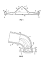
- Fig. 1
- shows a first cross-section of an exemplary embodiment of the invention along the width of the nozzle,
- Fig. 2
- shows a second cross-section of the embodiment shown in
fig. 1 at the middle of the nozzle, - Fig. 3
- shows a third cross-section of the embodiment shown in
fig. 1 where the neck is connected to the suction channel, - Fig. 4
- shows a fourth cross-section of the embodiment shown in
fig. 1 at the end of the nozzle, and - Fig. 5a-b
- show a simplified cross-section of the embodiment shown in
figs. 1-2 . -
Figures 1-4 show an exemplary embodiment of the nozzle according to the invention. Thenozzle 1 comprises a housing 2, aneck 3 and acoupling unit 4. - The housing 2 may comprise an
edge more recesses 5, as shown infigures 2-4 . Therecesses 5 may be configured to partially receive one or more elements (not shown) arranged to lie against a cleaning surface. The elements may be pivotally mounted inside therecess 5, e.g. via a pivot point located at both ends of therecess 5. - The housing may comprise an
edge nozzle 1, as shown infigure 1 , which each may comprise asecond recess 6. The second edges 2c, 2d may be lowered relative to thefirst edges nozzle 1 are closed off. Thesecond recess 6 may be configured to partially receive a wheel (not shown) which enables the nozzle to be moved more easily over the surface. The wheel may be mounted on a shaft (not shown) in thesecond recess 6 so that thenozzle 1 is kept a few millimetres above the surface. At least one of theedges edge nozzle 1 and which may be removed or rotated. This provides access to at least one of thefirst recesses edges 2c, 3d. - The housing 2 may be configured to form a
suction channel 7 inside the housing 2. Thesuction channel 7 may be defined by theedges 2a-d of the housing 2. Thesuction channel 7 comprises anopening 7a facing away from the nozzle, and anopening 7b (marked by dotted lines) facing theneck 3. The cross-sectional shape of thesuction channel 7 may be semicircular or square, as shown infigures 3-4 . The depth of thesuction channel 7 may decrease from theneck 3, i.e. the edge of theopening 7b, towards the end of thenozzle 1, e.g. theedge figures 1 ,3 and 4 . As shown infigure 1 , the bottom of thesuction channel 7 may be angled relative to theopening 7a so that the depth gradually or continuously decreases towards theends nozzle 1, thereby forming a wedge-shaped suction channel. The bottom may be linear and may be placed at an angle α between 2-10 degrees, preferably 5 degrees, as shown infigure 5a . Alternatively, the bottom may be curved, e.g. forming a C-shaped or S-shaped curve having at least one predetermined radius of curvature. This shape reduces the risk of having flow separation in the suction channel, thereby decreasing the pressure loss and thus increasing the flow velocity near the ends of the nozzle. - The
neck 3 is connected to theopening 7b of thesuction channel 7, as shown infigures 1 and 2 . At the opposite end, theneck 3 is connected to thecoupling unit 4. Theneck 3 may be shaped as a funnel, e.g. a rectangular shaped funnel, having a small opening at one end and a large opening at the other end. The small opening may be a circular opening which may be connected to thecoupling unit 4, as shown infigure 2 . The large opening may be formed by theopening 7b which may be shaped as a rectangular or substantially rectangular opening, as shown infigures 1-2 . Theneck 3 has two or moreinternal sides suction channel 7. -
Figures 5a-b show a simplified cross-section of the embodiment shown infigures 1-2 . The width A of theopening 7b may be equal to or smaller than the internal diameter B of the small opening connected to thecoupling unit 4, as shown infigures 2 and5b . The width C of theopening 7b may be equal to or greater than 30%, preferably between 30-70%, of the width D of theopening 7a. Thesides neck 3 may be linear or curved, e.g. having a radius of curvature equal or greater than 100mm. The shape of theneck 3 reduces the risk of having flow separation around the peripheral edges of theopening 7b, thus reducing pressure loss and thereby increasing the flow velocity at the ends of thenozzle 1. This provides a more uniform distribution of the flow velocity along the width of thenozzle 1. - The peripheral edges around the
opening 7b may be rounded (also called fairing) in order to prevent vortex shedding, thereby allowing the inflow to pass more freely, as shown infigures 1-2 . The edges along the bottom of thesuction channel 7 may be rounded, as shown infigures 3-4 . The shape of the neck 3 (and the suction channel 7) further reduces the noise level generated by thenozzle 1, since the inflow does not pass any sharp peripheral edges through thenozzle 1. - Tests have shown that the
nozzle 1 as described above with a suction capability of 30 L/s increases the flow velocity through the suction pipe to about 46.7m/s and increases the flow velocity near the ends of the suction channel to about 51.4m/s. This enables the width D of thesuction channel 7 to be increased, i.e. from 300 mm to 500 mm, while maintaining the same suction capability, thereby reducing the total cleaning time. - The shape of the
neck 3 may be curved so that thecoupling unit 4 may be positioned at an angle β perpendicular to the length of the housing 2, as shown infigures 2 and5b , e.g. in an angle β between 45-90 degrees. Thecoupling unit 4 may be positioned at a predetermined height E and length F from theopening 7a. The position of thecoupling unit 4 may be determined so that the inflow has an optimum flow path through theneck 3 with a minimal energy loss. In one embodiment the height E may be 40 mm and the length F may be 30 mm. This enables thenozzle 1 to reach difficult areas under articles of furniture. Thecoupling unit 4 may be configured to be coupled to a suction pipe or a suction hose, as shown infigures 2-4 .Figure 5b shows a construction, where the dimension B is larger than A. However, from a manufacturing point of view it may be desired to have essentially the same dimensions for A and B. - In one embodiment, the
coupling unit 4 may comprise a pivoting/rotating joint (not shown), enabling the suction pipe or hose to pivot/rotate relative to thenozzle 1, while maintaining thenozzle 1 close to the surface. The pivoting/rotating joint may be placed between thecoupling unit 4 and theneck 3.
Claims (12)
- A nozzle (1) for a cleaning device comprising:- a housing (2) having a suction channel (7) with a first opening (7a) facing away from the housing,- a neck (3) having a second opening (7b) and a third opening, said second opening being connected to the suction channel, and- a coupling unit (4) which is connected to the third opening of the neck, and which may be coupled to a suction pipe or a suction hose, characterized in that the suction channel (7) comprises a bottom, wherein the depth of the suction channel gradually or continuously decreases from the neck (3) towards ends of the nozzle (1) whereby the parts of the suction channel (7) between the neck (3) and the ends of the nozzle forms wedge-shaped suction channels, in which the bottom is positioned at an angle (α) between 2-12 degrees relative to the plane defined by the first opening (7a).
- A nozzle according to claim 1, wherein the neck (3) is configured as a funnel, wherein the second opening (7b) has a width (C) equal to or greater than 30% of the width (D) of the first opening (7a).
- A nozzle according to claim 1 or 2, wherein the width (C) of the second opening (7b) is between 30-70% of the width (D) of the first opening (7a).
- A nozzle according to any one of the claims 1 to 3, wherein the funnel comprises two sides (3a, 3b) which are connected to a bottom of the suction channel and where the transition between a funnel side (3a, 3b) and a bottom of the suction channel have a radius of curvature equal to or greater than than 50 to 100 mm, preferably greater than 100 mm.
- A nozzle according to any one of the preceding claims, wherein each funnel side (3a, 3b) is positioned with an angle between 25-55 degrees relative to the to the plane defined by first opening (7a), preferably 30-45 degrees.
- A nozzle according to any one of the preceding claims wherein the transition constituted by the neck (3) between the suction channel (7) and the coupling unit (4) has a radius of curvature of at least 20 mm, preferably at least 25-35 mm.
- A nozzle according to any one of the preceding claims wherein the bottom is positioned at an angle (α) between 2-10 degrees relative to the plane defined by the first opening (7a), preferably 9 degrees.
- A nozzle according to any one of the preceding claims, wherein the housing (2) has first and second edges (2a, 2b) extending along the width of the housing and having a recess, in which one or more elements arranged to lie against a surface may be placed, and wherein the elements are selected from a group of brushes, sliding elements or rubber lips.
- A nozzle according to claim 7, wherein the housing (2) comprises a third and fourth edges (2c, 2d) located at opposite ends of the housing (2) and having a recess, in which a wheel may be mounted on a shaft.
- A nozzle according to claim 8, wherein the elements arranged in the first edge and/or second edge (2a, 2b) may be replaced by rotating or removing either the third edge and/or fourth edge (2c, 2d) or a side plate facing away from the housing (2).
- A nozzle according to any one of the preceding claims, wherein the coupling unit (4) comprises coupling means, which may be coupled to the suction hose or suction pipe located at the free end of the coupling unit (4) and optionally a rotating/pivoting joint connected to the neck (3).
- A cleaning device comprising a cleaning unit having a filtration system connected to a suction module, which is arranged to suck up dirt, particles, solids or fluids from a surface, and a suction hose or pipe which may be connected to the cleaning unit and/or a nozzle, characterized in that the nozzle is a nozzle (1) as described in any one of the preceding claims.
Applications Claiming Priority (1)
| Application Number | Priority Date | Filing Date | Title |
|---|---|---|---|
| DKPA201200163 | 2012-02-29 |
Publications (3)
| Publication Number | Publication Date |
|---|---|
| EP2633792A2 true EP2633792A2 (en) | 2013-09-04 |
| EP2633792A3 EP2633792A3 (en) | 2015-11-11 |
| EP2633792B1 EP2633792B1 (en) | 2020-05-13 |
Family
ID=47900988
Family Applications (1)
| Application Number | Title | Priority Date | Filing Date |
|---|---|---|---|
| EP13388002.1A Active EP2633792B1 (en) | 2012-02-29 | 2013-02-27 | A nozzle for cleaning devices |
Country Status (1)
| Country | Link |
|---|---|
| EP (1) | EP2633792B1 (en) |
Cited By (1)
| Publication number | Priority date | Publication date | Assignee | Title |
|---|---|---|---|---|
| WO2025005275A1 (en) * | 2023-05-18 | 2025-01-02 | 株式会社コーワ | Vacuum-cleaner intake port |
Citations (1)
| Publication number | Priority date | Publication date | Assignee | Title |
|---|---|---|---|---|
| GB725395A (en) | 1953-06-11 | 1955-03-02 | Lewyt Corp | Improvements in vacuum cleaner nozzles |
Family Cites Families (5)
| Publication number | Priority date | Publication date | Assignee | Title |
|---|---|---|---|---|
| NL48723C (en) * | 1937-09-02 | |||
| GB707366A (en) * | 1952-02-09 | 1954-04-14 | Kooperativa Forbundet Forening | Improvements in suction cleaner nozzles |
| SE390251B (en) * | 1975-03-26 | 1976-12-13 | Electrolux Ab | VACUUM CLEANER NOZZLE |
| US4747179A (en) * | 1987-05-29 | 1988-05-31 | Shop-Vac Corporation | Nozzle with improved coupling for a vacuum device |
| DE4413223A1 (en) * | 1994-04-15 | 1995-10-19 | Vorwerk Co Interholding | Flow channel section for in particular a vacuum cleaner |
-
2013
- 2013-02-27 EP EP13388002.1A patent/EP2633792B1/en active Active
Patent Citations (1)
| Publication number | Priority date | Publication date | Assignee | Title |
|---|---|---|---|---|
| GB725395A (en) | 1953-06-11 | 1955-03-02 | Lewyt Corp | Improvements in vacuum cleaner nozzles |
Cited By (1)
| Publication number | Priority date | Publication date | Assignee | Title |
|---|---|---|---|---|
| WO2025005275A1 (en) * | 2023-05-18 | 2025-01-02 | 株式会社コーワ | Vacuum-cleaner intake port |
Also Published As
| Publication number | Publication date |
|---|---|
| EP2633792B1 (en) | 2020-05-13 |
| EP2633792A3 (en) | 2015-11-11 |
Similar Documents
| Publication | Publication Date | Title |
|---|---|---|
| JP5232195B2 (en) | Tools for surface treatment appliances | |
| RU2602049C1 (en) | Device for cleaning floors | |
| US20030140449A1 (en) | Vacuum cleaner nozzle assembly having edge-cleaning ducts | |
| KR102613447B1 (en) | Cleaner | |
| CN107105954B (en) | Vacuum cleaner nozzle with tilt adjustment element | |
| CN209421834U (en) | Cleaning head | |
| CN109953689B (en) | a cleaning head | |
| CN104837392B (en) | Head of vacuum suction cleaner | |
| EP2398368B1 (en) | Vacuum cleaner nozzle | |
| CN105491929A (en) | A nozzle for a vacuum cleaner | |
| CN203506607U (en) | Improved dust collector floor brush | |
| EP2633792B1 (en) | A nozzle for cleaning devices | |
| CN210643886U (en) | Dust collector suction nozzle and household dust collector comprising same | |
| CN104367268B (en) | Modified floor brush of dust collector | |
| CN110269544A (en) | It is provided with the cleaner suction nozzle of the slidingsurface with rounded back edge | |
| US12605028B2 (en) | Suction nozzle for extraction cleaner | |
| CN110269545A (en) | The cleaner suction nozzle of rib is scraped after being provided with | |
| CN215128026U (en) | Floor brush for easy accumulation of stains | |
| CN209301010U (en) | A kind of scrubbing brush dust sucting pipeline and dust catcher | |
| JP2006212279A (en) | Squeegee and vacuum cleaner with this squeegee | |
| CN110710928A (en) | a surface cleaning head | |
| CN208018990U (en) | Air port item easy to clean | |
| CN106108778B (en) | Dust collector floor brush and dust collector | |
| CN209300992U (en) | A kind of scrubbing brush air inlet duct and dust catcher | |
| EP2948037B1 (en) | Vacuum cleaning head |
Legal Events
| Date | Code | Title | Description |
|---|---|---|---|
| PUAI | Public reference made under article 153(3) epc to a published international application that has entered the european phase |
Free format text: ORIGINAL CODE: 0009012 |
|
| AK | Designated contracting states |
Kind code of ref document: A2 Designated state(s): AL AT BE BG CH CY CZ DE DK EE ES FI FR GB GR HR HU IE IS IT LI LT LU LV MC MK MT NL NO PL PT RO RS SE SI SK SM TR |
|
| AX | Request for extension of the european patent |
Extension state: BA ME |
|
| PUAL | Search report despatched |
Free format text: ORIGINAL CODE: 0009013 |
|
| AK | Designated contracting states |
Kind code of ref document: A3 Designated state(s): AL AT BE BG CH CY CZ DE DK EE ES FI FR GB GR HR HU IE IS IT LI LT LU LV MC MK MT NL NO PL PT RO RS SE SI SK SM TR |
|
| AX | Request for extension of the european patent |
Extension state: BA ME |
|
| RIC1 | Information provided on ipc code assigned before grant |
Ipc: A47L 9/02 20060101AFI20151002BHEP |
|
| 17P | Request for examination filed |
Effective date: 20160511 |
|
| RAX | Requested extension states of the european patent have changed |
Extension state: ME Payment date: 20160511 Extension state: BA Payment date: 20160511 |
|
| RBV | Designated contracting states (corrected) |
Designated state(s): AL AT BE BG CH CY CZ DE DK EE ES FI FR GB GR HR HU IE IS IT LI LT LU LV MC MK MT NL NO PL PT RO RS SE SI SK SM TR |
|
| GRAP | Despatch of communication of intention to grant a patent |
Free format text: ORIGINAL CODE: EPIDOSNIGR1 |
|
| STAA | Information on the status of an ep patent application or granted ep patent |
Free format text: STATUS: GRANT OF PATENT IS INTENDED |
|
| INTG | Intention to grant announced |
Effective date: 20200107 |
|
| RIN1 | Information on inventor provided before grant (corrected) |
Inventor name: LARSEN, PETER NOEHR Inventor name: AMAJID, JUAN Inventor name: JARLHELT, KEN |
|
| GRAS | Grant fee paid |
Free format text: ORIGINAL CODE: EPIDOSNIGR3 |
|
| GRAA | (expected) grant |
Free format text: ORIGINAL CODE: 0009210 |
|
| STAA | Information on the status of an ep patent application or granted ep patent |
Free format text: STATUS: THE PATENT HAS BEEN GRANTED |
|
| AK | Designated contracting states |
Kind code of ref document: B1 Designated state(s): AL AT BE BG CH CY CZ DE DK EE ES FI FR GB GR HR HU IE IS IT LI LT LU LV MC MK MT NL NO PL PT RO RS SE SI SK SM TR |
|
| AX | Request for extension of the european patent |
Extension state: BA ME |
|
| RAP1 | Party data changed (applicant data changed or rights of an application transferred) |
Owner name: NILFISK A/S |
|
| REG | Reference to a national code |
Ref country code: GB Ref legal event code: FG4D |
|
| REG | Reference to a national code |
Ref country code: CH Ref legal event code: EP |
|
| REG | Reference to a national code |
Ref country code: DE Ref legal event code: R096 Ref document number: 602013069030 Country of ref document: DE |
|
| REG | Reference to a national code |
Ref country code: AT Ref legal event code: REF Ref document number: 1269110 Country of ref document: AT Kind code of ref document: T Effective date: 20200615 |
|
| REG | Reference to a national code |
Ref country code: LT Ref legal event code: MG4D |
|
| REG | Reference to a national code |
Ref country code: NL Ref legal event code: MP Effective date: 20200513 |
|
| PG25 | Lapsed in a contracting state [announced via postgrant information from national office to epo] |
Ref country code: IS Free format text: LAPSE BECAUSE OF FAILURE TO SUBMIT A TRANSLATION OF THE DESCRIPTION OR TO PAY THE FEE WITHIN THE PRESCRIBED TIME-LIMIT Effective date: 20200913 Ref country code: GR Free format text: LAPSE BECAUSE OF FAILURE TO SUBMIT A TRANSLATION OF THE DESCRIPTION OR TO PAY THE FEE WITHIN THE PRESCRIBED TIME-LIMIT Effective date: 20200814 Ref country code: NO Free format text: LAPSE BECAUSE OF FAILURE TO SUBMIT A TRANSLATION OF THE DESCRIPTION OR TO PAY THE FEE WITHIN THE PRESCRIBED TIME-LIMIT Effective date: 20200813 Ref country code: SE Free format text: LAPSE BECAUSE OF FAILURE TO SUBMIT A TRANSLATION OF THE DESCRIPTION OR TO PAY THE FEE WITHIN THE PRESCRIBED TIME-LIMIT Effective date: 20200513 Ref country code: FI Free format text: LAPSE BECAUSE OF FAILURE TO SUBMIT A TRANSLATION OF THE DESCRIPTION OR TO PAY THE FEE WITHIN THE PRESCRIBED TIME-LIMIT Effective date: 20200513 Ref country code: LT Free format text: LAPSE BECAUSE OF FAILURE TO SUBMIT A TRANSLATION OF THE DESCRIPTION OR TO PAY THE FEE WITHIN THE PRESCRIBED TIME-LIMIT Effective date: 20200513 Ref country code: PT Free format text: LAPSE BECAUSE OF FAILURE TO SUBMIT A TRANSLATION OF THE DESCRIPTION OR TO PAY THE FEE WITHIN THE PRESCRIBED TIME-LIMIT Effective date: 20200914 |
|
| PG25 | Lapsed in a contracting state [announced via postgrant information from national office to epo] |
Ref country code: LV Free format text: LAPSE BECAUSE OF FAILURE TO SUBMIT A TRANSLATION OF THE DESCRIPTION OR TO PAY THE FEE WITHIN THE PRESCRIBED TIME-LIMIT Effective date: 20200513 Ref country code: HR Free format text: LAPSE BECAUSE OF FAILURE TO SUBMIT A TRANSLATION OF THE DESCRIPTION OR TO PAY THE FEE WITHIN THE PRESCRIBED TIME-LIMIT Effective date: 20200513 Ref country code: RS Free format text: LAPSE BECAUSE OF FAILURE TO SUBMIT A TRANSLATION OF THE DESCRIPTION OR TO PAY THE FEE WITHIN THE PRESCRIBED TIME-LIMIT Effective date: 20200513 Ref country code: BG Free format text: LAPSE BECAUSE OF FAILURE TO SUBMIT A TRANSLATION OF THE DESCRIPTION OR TO PAY THE FEE WITHIN THE PRESCRIBED TIME-LIMIT Effective date: 20200813 |
|
| REG | Reference to a national code |
Ref country code: AT Ref legal event code: MK05 Ref document number: 1269110 Country of ref document: AT Kind code of ref document: T Effective date: 20200513 |
|
| PG25 | Lapsed in a contracting state [announced via postgrant information from national office to epo] |
Ref country code: NL Free format text: LAPSE BECAUSE OF FAILURE TO SUBMIT A TRANSLATION OF THE DESCRIPTION OR TO PAY THE FEE WITHIN THE PRESCRIBED TIME-LIMIT Effective date: 20200513 Ref country code: AL Free format text: LAPSE BECAUSE OF FAILURE TO SUBMIT A TRANSLATION OF THE DESCRIPTION OR TO PAY THE FEE WITHIN THE PRESCRIBED TIME-LIMIT Effective date: 20200513 |
|
| PG25 | Lapsed in a contracting state [announced via postgrant information from national office to epo] |
Ref country code: RO Free format text: LAPSE BECAUSE OF FAILURE TO SUBMIT A TRANSLATION OF THE DESCRIPTION OR TO PAY THE FEE WITHIN THE PRESCRIBED TIME-LIMIT Effective date: 20200513 Ref country code: CZ Free format text: LAPSE BECAUSE OF FAILURE TO SUBMIT A TRANSLATION OF THE DESCRIPTION OR TO PAY THE FEE WITHIN THE PRESCRIBED TIME-LIMIT Effective date: 20200513 Ref country code: ES Free format text: LAPSE BECAUSE OF FAILURE TO SUBMIT A TRANSLATION OF THE DESCRIPTION OR TO PAY THE FEE WITHIN THE PRESCRIBED TIME-LIMIT Effective date: 20200513 Ref country code: AT Free format text: LAPSE BECAUSE OF FAILURE TO SUBMIT A TRANSLATION OF THE DESCRIPTION OR TO PAY THE FEE WITHIN THE PRESCRIBED TIME-LIMIT Effective date: 20200513 Ref country code: DK Free format text: LAPSE BECAUSE OF FAILURE TO SUBMIT A TRANSLATION OF THE DESCRIPTION OR TO PAY THE FEE WITHIN THE PRESCRIBED TIME-LIMIT Effective date: 20200513 Ref country code: SM Free format text: LAPSE BECAUSE OF FAILURE TO SUBMIT A TRANSLATION OF THE DESCRIPTION OR TO PAY THE FEE WITHIN THE PRESCRIBED TIME-LIMIT Effective date: 20200513 Ref country code: EE Free format text: LAPSE BECAUSE OF FAILURE TO SUBMIT A TRANSLATION OF THE DESCRIPTION OR TO PAY THE FEE WITHIN THE PRESCRIBED TIME-LIMIT Effective date: 20200513 |
|
| REG | Reference to a national code |
Ref country code: DE Ref legal event code: R097 Ref document number: 602013069030 Country of ref document: DE |
|
| PG25 | Lapsed in a contracting state [announced via postgrant information from national office to epo] |
Ref country code: SK Free format text: LAPSE BECAUSE OF FAILURE TO SUBMIT A TRANSLATION OF THE DESCRIPTION OR TO PAY THE FEE WITHIN THE PRESCRIBED TIME-LIMIT Effective date: 20200513 Ref country code: PL Free format text: LAPSE BECAUSE OF FAILURE TO SUBMIT A TRANSLATION OF THE DESCRIPTION OR TO PAY THE FEE WITHIN THE PRESCRIBED TIME-LIMIT Effective date: 20200513 |
|
| PLBE | No opposition filed within time limit |
Free format text: ORIGINAL CODE: 0009261 |
|
| STAA | Information on the status of an ep patent application or granted ep patent |
Free format text: STATUS: NO OPPOSITION FILED WITHIN TIME LIMIT |
|
| 26N | No opposition filed |
Effective date: 20210216 |
|
| PG25 | Lapsed in a contracting state [announced via postgrant information from national office to epo] |
Ref country code: SI Free format text: LAPSE BECAUSE OF FAILURE TO SUBMIT A TRANSLATION OF THE DESCRIPTION OR TO PAY THE FEE WITHIN THE PRESCRIBED TIME-LIMIT Effective date: 20200513 |
|
| PG25 | Lapsed in a contracting state [announced via postgrant information from national office to epo] |
Ref country code: MC Free format text: LAPSE BECAUSE OF FAILURE TO SUBMIT A TRANSLATION OF THE DESCRIPTION OR TO PAY THE FEE WITHIN THE PRESCRIBED TIME-LIMIT Effective date: 20200513 |
|
| GBPC | Gb: european patent ceased through non-payment of renewal fee |
Effective date: 20210227 |
|
| REG | Reference to a national code |
Ref country code: BE Ref legal event code: MM Effective date: 20210228 |
|
| PG25 | Lapsed in a contracting state [announced via postgrant information from national office to epo] |
Ref country code: CH Free format text: LAPSE BECAUSE OF NON-PAYMENT OF DUE FEES Effective date: 20210228 Ref country code: LI Free format text: LAPSE BECAUSE OF NON-PAYMENT OF DUE FEES Effective date: 20210228 Ref country code: LU Free format text: LAPSE BECAUSE OF NON-PAYMENT OF DUE FEES Effective date: 20210227 |
|
| PG25 | Lapsed in a contracting state [announced via postgrant information from national office to epo] |
Ref country code: IE Free format text: LAPSE BECAUSE OF NON-PAYMENT OF DUE FEES Effective date: 20210227 Ref country code: GB Free format text: LAPSE BECAUSE OF NON-PAYMENT OF DUE FEES Effective date: 20210227 |
|
| PG25 | Lapsed in a contracting state [announced via postgrant information from national office to epo] |
Ref country code: BE Free format text: LAPSE BECAUSE OF NON-PAYMENT OF DUE FEES Effective date: 20210228 |
|
| PG25 | Lapsed in a contracting state [announced via postgrant information from national office to epo] |
Ref country code: HU Free format text: LAPSE BECAUSE OF FAILURE TO SUBMIT A TRANSLATION OF THE DESCRIPTION OR TO PAY THE FEE WITHIN THE PRESCRIBED TIME-LIMIT; INVALID AB INITIO Effective date: 20130227 |
|
| P01 | Opt-out of the competence of the unified patent court (upc) registered |
Effective date: 20230515 |
|
| PG25 | Lapsed in a contracting state [announced via postgrant information from national office to epo] |
Ref country code: CY Free format text: LAPSE BECAUSE OF FAILURE TO SUBMIT A TRANSLATION OF THE DESCRIPTION OR TO PAY THE FEE WITHIN THE PRESCRIBED TIME-LIMIT Effective date: 20200513 |
|
| REG | Reference to a national code |
Ref country code: DE Ref legal event code: R081 Ref document number: 602013069030 Country of ref document: DE Owner name: NILFISK A/S, DK Free format text: FORMER OWNER: NILFISK A/S, BRONDBY, DK |
|
| PG25 | Lapsed in a contracting state [announced via postgrant information from national office to epo] |
Ref country code: MK Free format text: LAPSE BECAUSE OF FAILURE TO SUBMIT A TRANSLATION OF THE DESCRIPTION OR TO PAY THE FEE WITHIN THE PRESCRIBED TIME-LIMIT Effective date: 20200513 |
|
| PG25 | Lapsed in a contracting state [announced via postgrant information from national office to epo] |
Ref country code: MT Free format text: LAPSE BECAUSE OF FAILURE TO SUBMIT A TRANSLATION OF THE DESCRIPTION OR TO PAY THE FEE WITHIN THE PRESCRIBED TIME-LIMIT Effective date: 20200513 |
|
| PGFP | Annual fee paid to national office [announced via postgrant information from national office to epo] |
Ref country code: DE Payment date: 20250122 Year of fee payment: 13 |
|
| PGFP | Annual fee paid to national office [announced via postgrant information from national office to epo] |
Ref country code: FR Payment date: 20250122 Year of fee payment: 13 |
|
| PGFP | Annual fee paid to national office [announced via postgrant information from national office to epo] |
Ref country code: IT Payment date: 20250121 Year of fee payment: 13 |
|
| PG25 | Lapsed in a contracting state [announced via postgrant information from national office to epo] |
Ref country code: TR Free format text: LAPSE BECAUSE OF FAILURE TO SUBMIT A TRANSLATION OF THE DESCRIPTION OR TO PAY THE FEE WITHIN THE PRESCRIBED TIME-LIMIT Effective date: 20200513 |