EP2633596B1 - Windenergieanlage - Google Patents
Windenergieanlage Download PDFInfo
- Publication number
- EP2633596B1 EP2633596B1 EP11776077.7A EP11776077A EP2633596B1 EP 2633596 B1 EP2633596 B1 EP 2633596B1 EP 11776077 A EP11776077 A EP 11776077A EP 2633596 B1 EP2633596 B1 EP 2633596B1
- Authority
- EP
- European Patent Office
- Prior art keywords
- grid
- voltage
- overvoltage
- wind turbine
- resistor
- Prior art date
- Legal status (The legal status is an assumption and is not a legal conclusion. Google has not performed a legal analysis and makes no representation as to the accuracy of the status listed.)
- Not-in-force
Links
- 239000003990 capacitor Substances 0.000 claims description 14
- 238000000034 method Methods 0.000 claims description 13
- 230000000295 complement effect Effects 0.000 claims description 2
- 238000010586 diagram Methods 0.000 description 10
- 238000011217 control strategy Methods 0.000 description 9
- 230000005540 biological transmission Effects 0.000 description 7
- 230000008901 benefit Effects 0.000 description 5
- 238000011835 investigation Methods 0.000 description 2
- 238000010248 power generation Methods 0.000 description 2
- 238000010521 absorption reaction Methods 0.000 description 1
- 230000003213 activating effect Effects 0.000 description 1
- 230000007423 decrease Effects 0.000 description 1
- 230000000694 effects Effects 0.000 description 1
- 230000010354 integration Effects 0.000 description 1
- 230000002045 lasting effect Effects 0.000 description 1
- 238000004519 manufacturing process Methods 0.000 description 1
- 230000000630 rising effect Effects 0.000 description 1
- 239000004065 semiconductor Substances 0.000 description 1
- 239000007787 solid Substances 0.000 description 1
- 238000001228 spectrum Methods 0.000 description 1
- 230000001360 synchronised effect Effects 0.000 description 1
- 230000007704 transition Effects 0.000 description 1
Images




Classifications
-
- H—ELECTRICITY
- H02—GENERATION; CONVERSION OR DISTRIBUTION OF ELECTRIC POWER
- H02P—CONTROL OR REGULATION OF ELECTRIC MOTORS, ELECTRIC GENERATORS OR DYNAMO-ELECTRIC CONVERTERS; CONTROLLING TRANSFORMERS, REACTORS OR CHOKE COILS
- H02P9/00—Arrangements for controlling electric generators for the purpose of obtaining a desired output
- H02P9/006—Means for protecting the generator by using control
-
- H—ELECTRICITY
- H02—GENERATION; CONVERSION OR DISTRIBUTION OF ELECTRIC POWER
- H02H—EMERGENCY PROTECTIVE CIRCUIT ARRANGEMENTS
- H02H7/00—Emergency protective circuit arrangements specially adapted for specific types of electric machines or apparatus or for sectionalised protection of cable or line systems, and effecting automatic switching in the event of an undesired change from normal working conditions
- H02H7/06—Emergency protective circuit arrangements specially adapted for specific types of electric machines or apparatus or for sectionalised protection of cable or line systems, and effecting automatic switching in the event of an undesired change from normal working conditions for dynamo-electric generators; for synchronous capacitors
- H02H7/065—Emergency protective circuit arrangements specially adapted for specific types of electric machines or apparatus or for sectionalised protection of cable or line systems, and effecting automatic switching in the event of an undesired change from normal working conditions for dynamo-electric generators; for synchronous capacitors against excitation faults
-
- H—ELECTRICITY
- H02—GENERATION; CONVERSION OR DISTRIBUTION OF ELECTRIC POWER
- H02M—APPARATUS FOR CONVERSION BETWEEN AC AND AC, BETWEEN AC AND DC, OR BETWEEN DC AND DC, AND FOR USE WITH MAINS OR SIMILAR POWER SUPPLY SYSTEMS; CONVERSION OF DC OR AC INPUT POWER INTO SURGE OUTPUT POWER; CONTROL OR REGULATION THEREOF
- H02M1/00—Details of apparatus for conversion
- H02M1/32—Means for protecting converters other than automatic disconnection
-
- Y—GENERAL TAGGING OF NEW TECHNOLOGICAL DEVELOPMENTS; GENERAL TAGGING OF CROSS-SECTIONAL TECHNOLOGIES SPANNING OVER SEVERAL SECTIONS OF THE IPC; TECHNICAL SUBJECTS COVERED BY FORMER USPC CROSS-REFERENCE ART COLLECTIONS [XRACs] AND DIGESTS
- Y02—TECHNOLOGIES OR APPLICATIONS FOR MITIGATION OR ADAPTATION AGAINST CLIMATE CHANGE
- Y02E—REDUCTION OF GREENHOUSE GAS [GHG] EMISSIONS, RELATED TO ENERGY GENERATION, TRANSMISSION OR DISTRIBUTION
- Y02E10/00—Energy generation through renewable energy sources
- Y02E10/70—Wind energy
- Y02E10/76—Power conversion electric or electronic aspects
Definitions
- the present invention relates to a system and/or a method for a wind turbine generator (WTG).
- WTG wind turbine generator
- Wind farms are commonly located in remote areas to take advantage of good wind conditions. This may require long transmission lines to connect the wind farms to the rest of the power grid. Because of the long transmission lines and extreme conditions in the remote areas the wind farms may have to be designed to withstand relatively high levels of fault conditions, this is also necessary in order to ensure good connectivity with the grid Overvoltage is one such fault condition which should be handled properly.
- the grid code specifies what fault conditions a wind farm must be designed to withstand before tripping. This directly affects the design of the WTG.
- the dotted curve 1 corresponds to Australia where the temporary overvoltage up to 1.6 pu can be experienced.
- the overvoltage in Figure 1 could be up to 2 pu for a short duration.
- the solid curve 2 covers temporary overvoltage grid requirement for all other countries.
- Wind farm owners and wind turbine manufacturers may wish to protect the power electronics and power components in converter systems of wind turbines from damage caused by the overvoltage.
- the easiest solution to protect the turbines is by disconnection from the grid.
- transmission system operators may want to maintain grid connectivity of wind farm in case of overvoltage.
- the relevant grid code may require the turbine to stay connected to the grid during such overvoltage events.
- the invention proposes using a current control strategy for a WTG during an overvoltage condition. This may have the advantage that the power components of the WTG are not damaged, that the WTG is able to stay connected to the grid during the overvoltage event.
- the series resistors may be used for pre-charge operation of the DC-link capacitors if required.
- a system for a wind turbine generator comprising:
- the controller may be configured to determine the current control reference signal according to at least one of an impedance of the voltage limiting elements, the line voltage, a grid side converter voltage and a grid frequency.
- the controller may be configured to shut down the wind turbine generator if the line voltage is above the predetermined threshold for longer than a predetermined period.
- Each voltage limiting element may comprises a resistor in parallel with a bypass switch.
- Each voltage limiting element may further comprise a switch in series with the resistor.
- the controller is configured to open the bypass switch and close the switch in series with the resistor when the line voltage is above the predetermined threshold.
- the wind turbine may be multiphase, the gate terminals of series connected switch for each phase may be coupled together and the gate terminals of each bypass switch for each phase may be coupled together and the bypass switches may be simultaneously operated using one gating signal and the series switches may be simultaneously operated using one switching signal.
- a wind turbine generator comprising:
- the controller may be configured to supply reactive currents required by a filter capacitor bank between the grid side converter and the turbine transformer either by the grid side converter or the grid.
- the wind turbine generator may further comprise a dump load resistor, and the controller may be configured to connect the dump load resistor to the DC-link according to a duty cycle determined based a power to be dissipated when the line voltage is above the predetermined threshold.
- a pulse width modulated drive signal may be provided to a load dump resistor switch when it is determined during an overvoltage that there is an excess active power which cannot be delivered to the grid.
- the method may further comprise providing a complementary close signal to a set of series resistor switches simultaneously with the open signal.
- the current control reference signal may be at least one of an active and a reactive current control reference signal.
- the method may further comprise determining a reactive current control reference signal to control the overvoltage by absorbing reactive power if the overvoltage is between a lower threshold and the maximum threshold.
- the current control reference signal may be determined based on at least one of the overvoltage, a voltage limiting impedance value, a grid side converter voltage and a grid frequency.
- a WTG generally includes a set of blades, a generator and a power converter.
- the turbine blades are rotated about a shaft by the wind and are mounted in a nacelle on a tower relatively high off the ground to ensure good airflow.
- the electrical generator is driven by the rotating shaft to produce typically alternating current (AC) voltage which varies in magnitude and frequency according to the wind speed.
- a gearbox may be used to step up the slow rotational speed of the shaft to a high rotational speed suitable for operating the generator.
- the generator may either be synchronous or asynchronous.
- the power convertor converts and transfers power from the generator to the grid as described below.
- Figure 2 shows an electrical system of the wind turbine according to an embodiment.
- the electrical system includes a generator 101, a power converter 102 and a main transformer 103.
- the power converter 102 includes a generator-side converter 110 and a grid-side converter 111 connected via a direct current (DC) link 112.
- the DC-link 112 includes a DC-link capacitor 113.
- the generator 101 converts mechanical energy to electrical energy having AC (alternating current) voltage and current (collectively referred to as "AC signals"), and provides the generated AC signals to the generator-side converter 110.
- the AC signals from the generator have a variable frequency, due to varying wind.
- the generator-side converter 110 converts or rectifies the AC signals to a DC (direct current) voltage and a DC current (collectively know as "DC signals”) towards the DC-link 112.
- a load dump resistor R CH and switch S CH 114 is provided to control the DC voltage on the DC-link 112 by absorbing any excess amount of active power.
- the grid-side converter 111 converts the DC signals from the DC-link 112 into fixed frequency AC signals for a power grid 107.
- the transformer 103 transforms the grid voltage to a suitable level on the low voltage side according to the drive train system hardware design.
- the power output of the grid-side converter 111 is fed to the power grid 107 through main transformer 103.
- the transmissions lines may be connected directly to the grid or, if in a wind farm, join with other transmission lines at a point of common connection before connecting to the grid.
- Filters 115 in the form of capacitors, inductors and resistors are also located between the grid-side converter 111 and the power grid 102.
- a passive filter carries two branches: a main harmonic filter branch (capacitor banks) to absorb harmonics and a resonance branch (capacitors, small chokes and small resistors) to damp resonance phenomenon.
- the filter may also include other components such as contactors, fuses, sensors etc.
- the electrical system described with reference to Figure 2 is only an example of the electrical configuration of the wind turbine and only the main components are shown to illustrate the embodiments.
- the present invention should not be limited to the exact electrical system configuration shown in Figure 2 .
- Other electrical configurations are possible.
- many components in the electrical system of the wind turbine are not shown in Figure 2 .
- the electrical system may include filters between the generator 101 and the power converter 102.
- the power generated by the WTG is determined by power reference or wind speed. However it may be desirable for the WTG to vary the amount of reactive power that is exchanged with the grid to provide better support to the grid. For example during steady state or normal conditions the grid will usually benefit from the WTG exchanging reactive power to meet the demanded power factor.
- the amount of reactive power support is determined by the grid requirements especially as demanded by the power plant or the grid operator. In the low voltage grid fault conditions typically the reactive power is provided from the WTG to boost up the grid voltage. Whereas in the high voltage grid fault conditions typically the reactive power is absorbed by the WTG to reduce the grid voltage.
- v G Grid side converter output voltage
- v L Voltage drop across grid choke
- v C Voltage at capacitor terminals
- v T Voltage at transformer low voltage terminals
- the nominal voltage range is typically in the range of 0.9-1.1pu. However, nominal voltage range and overvoltage level changes from country to country. A line voltage value which exceeds a nominal voltage range can be classified as an overvoltage. In order to comply with the grid code mentioned above, the WTG should be able to operate in spite of overvoltage event for certain duration. A method to handle overvoltage is described below.
- FIG. 6 shows a WTG 600 according to an embodiment.
- a set of three series resistors 602 are connected in series with the filter output 604.
- a bypass switch is provided for each resistor.
- bypass switches [S 1a , S 1b , S 1c ] are operated together with only one gating signal.
- a set of series switches [S 2a , S 2b , S 2c ], in series with the resistors 602, are operated together with only one gating signal.
- switches [S 1a , S 1b, S 1c ] are closed and switches [S 2a , S 2b , S 2c ] are open, inclusive of overvoltage situation shown in Figure 4 .
- the bypass switches [S 1a , S 1b , S 1c ] and the series switches [S 2a , S 2b , S 2c ] may be operated using more than one gating signals in other embodiments.
- the WTG 600 includes a controller 606.
- the controller 606 controls the operation of the converters, the bypass and series switches [S 2a , S 2b , S 2c ] [S 1a , S 1b , S 1c ] and the load dump switch S CH 114 for each WTG.
- the electrical system shown in Figure 6 is a 3-phase system. For each phase, each resistor is connected in series between the filter output and the transformer to limit the voltage v C seen at the filter terminals through power converter operation i.e. even if voltage v T is very high, the voltage v C is within converter system design limits. Hence, these series resistors 602 can be called voltage limiting elements.
- the Figure 6 shows the suggested location of these series resistors 602. However, they can be placed at other locations between grid side power converter and the transformer.
- the switches are bi-direction power semiconductor switches such as the one shown in Figure 7 according to an embodiment.
- the transition from [S 1a , S 1b , S 1c ] to [S 2a , S 2b , S 2c ] or vice versa can be done in a few micro seconds and hence fast control is possible.
- the power electronic switch may be an IGBT, IGCT, thyristor etc.
- all the switches [S 1a , S 1b , S 1c ] can be switched on and off together Using the same gating signal from the controller 606.
- the two IGBTs use the same gating signal, and the same applies to other two phases (S 1b and S 1c ).
- bypass switches [S 1a , S 1b , S 1c ] and the series ' switches [S 2a , S 2b , S 2c ] may be operated using more than one gating signal in other embodiments. Other arrangements are also possible. It should also be noted that series switches [S 2a , S 2b , S 2c ] are optional and may be eliminated in other embodiments.
- the load dump resistor in the DC-link is used to temporarily absorb the excess active power.
- the controller will determine an appropriate duty ratio for activating the load dump resistor to keep the DC-link voltage within designed limits by absorbing the excess active power.
- the current that flows into the dump resistor mainly comes from the active power from the electrical power generator.
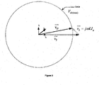
- a small active current I a may also flow to the load dump resistor which is needed for the voltage balancing through the series resistors 602 as per Figure 8 .
- the RI a +j ⁇ LI r is the voltage drop along the voltage v T where as -RI r +j ⁇ LI a is the voltage drop perpendicular to the voltage vector v T .
- the vector sum of RI a +j ⁇ LI r and -RI r +j ⁇ mLI a is given as I g (R+j ⁇ L).
- the vector sum of voltage vector v T and voltage drop vector I g (R+j ⁇ L) will decide the voltage to be applied from the power converter.
- the design of series resistor will be different from what is described for the above case i.e.
- I a and I r current references are determined they are provided to the grid side converter control (which may be the controller 606) which are used by the converter control algorithm and required voltage v G is produced by the converter which will eventually handle the grid overvoltage as described above with reference to Figures 8-10 .
- the reactive current required by the filter capacitors bank C in Figure 6 can be supplied from either converter or the grid. Accordingly, the reactive current requirement from the converter or the grid will be affected.
- FIG 11 shows a method 1100 for controlling the WTG according to an embodiment.
- the turbine shifts from the normal power generation mode 1104 to the overvoltage control mode.
- the controller inserts the series resistors 1106 and controls Ig accordingly as described above in Figure 8 - Figure 10 .
- the voltage v Tmax depends on the power converter voltage and current rating.
- the dump load resistor is connected to the DC-link at a duty cycle determined based on the active power to be dissipated.
- an overvoltage lasts for a few tens to hundreds of milliseconds.
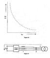
- a waiting time t OV can be provided as shown in Figure 12 ; typically the higher the overvoltage level, the shorter the waiting time. If the overvoltage is still present after the determined tov 1110 then the turbine is instructed to shutdown 1112.
- Figure 15 shows a method 1500 for controlling the WTG according to another embodiment.
- the turbine shifts from the normal power generation mode 1504 to the overvoltage control mode.
- the controller inserts the series resistors 1506 and controls I g accordingly.
- An additional advantage of using the resistor with bypass switches shown in Figure 6 may be pre-charge operation of the DC-link capacitors.
- the pre-charge operation is required when the converter system is started.
- the resistors with bypass switches in Figure 6 can be used for both the operations overvoltage handling (primary objective) and pre-charge operation (secondary objective).
- Figure 13 shows a diagram illustrating the pre-charge operation of the DC-link capacitors.
- [S 1a , S 1b , S 1c ] are open and [S 2a , S 2b , S 2c ] are closed.
- the pre-charge operation i.e. charging of the DC-link capacitors happens through the resistors, choke and grid rectifier.
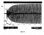
- Figure 14 shows the waveforms for this operation.
- the DC-link voltage 1400 and the current 1402 flowing between the converter and the rectifier voltage 1404 are shown during the pre-charge operation lasting for a few seconds.
Landscapes
- Engineering & Computer Science (AREA)
- Power Engineering (AREA)
- Control Of Eletrric Generators (AREA)
Claims (16)
- System für eine Windkraftanlage, enthaltend:eine Gruppe von Spannungsbegrenzungselementen (602) undeine Steuereinrichtung (606), die dafür konfiguriert ist, die Spannungsbegrenzungselemente (602) zu überbrücken, wenn eine Leitungsspannung unter einem vorbestimmten Schwellenwert liegt, und dafür konfiguriert ist, jedes Spannungsbegrenzungselement (602) zwischen einen netzseitigen Wandler (111) und einen Anlagentransformator (103) der Windkraftanlage in Reihe zu schalten und ein Stromsteuerungsreferenzsignal zur Steuerung des netzseitigen Wandlers (111) festzulegen (um einen festgelegten Strom zu erzeugen), wenn die Leitungsspannung über dem vorbestimmten Schwellenwert liegt.
- System nach Anspruch 1, bei welchem die Steuereinrichtung dafür konfiguriert ist, das Stromsteuerungsreferenzsignal gemäß mindestens einem der Faktoren Impedanz der Spannungsbegrenzungselemente, Leitungsspannung, Spannung des netzseitigen Wandlers und Netzfrequenz festzulegen.
- System nach Anspruch 1 oder 2, bei welchem die Steuereinrichtung dafür konfiguriert ist, die Windkraftanlage abzuschalten, wenn die Leitungsspannung länger als eine vorbestimmte Zeitdauer über dem vorbestimmten Schwellenwert liegt.
- System nach einem der vorhergehenden Ansprüche, bei welchem jedes Spannungsbegrenzungselement einen mit einem Überbrückungsschalter (S1a, S1b, S1c) parallel geschalteten Widerstand aufweist.
- System nach Anspruch 4, bei welchem jedes Spannungsbegrenzungselement ferner einen mit dem Widerstand in Reihe geschalteten Schalter (S2a, S2b, S2c) aufweist.
- System nach Anspruch 5, bei welchem die Steuereinrichtung (606) dafür konfiguriert ist, den Überbrückungsschalter (S1a, S1b, S1c) zu öffnen und den mit dem Widerstand in Reihe geschalteten Schalter (S2a, S2b, S2c) zu schließen, wenn die Leitungsspannung über dem vorbestimmten Schwellenwert liegt.
- System nach Anspruch 5 oder 6, bei welchem die Windkraftanlage mehrphasig ist, die Gate-Klemmen des in Reihe geschalteten Schalters für jede Phase miteinander gekoppelt sind und die Gate-Klemmen jedes Überbrückungsschalters (S1a, S1b, S1c) für jede Phase miteinander gekoppelt sind und die Überbrückungsschalter (S1a, S1b, S1c) dafür konfiguriert sind, unter Verwendung eines Gattersignals gleichzeitig zu arbeiten und die in Reihe geschalteten Schalter dafür konfiguriert sind, unter Verwendung eines Schaltsignals gleichzeitig zu arbeiten.
- Windkraftanlage, enthaltend:einen elektrischen Generator (101), der für die Erzeugung von Wechselstromsignalen konfiguriert ist;einen generatorseitigen Wandler (110), der dafür konfiguriert ist, die Wechselstromsignale aus dem Wechselstromgenerator in Gleichstromsignale an eine Gleichstromverbindung (112) umzuwandeln oder gleichzurichten,einen netzseitigen Wandler (111), der dafür konfiguriert ist, die Gleichstromsignale von der Gleichstromverbindung (112) in ein Wechselstromsignal mit festgelegter Frequenz umzuwandeln,einen Anlagentransformator (103), der dafür konfiguriert ist, die Wechselstromsignale mit festgelegter Frequenz auf einen geeigneten Spannungspegel zu transformieren, undein System nach einem der vorhergehenden Ansprüche, wobei jedes Spannungsbegrenzungselement zwischen dem netzseitigen Wandler (111) und dem Anlagentransformator (103) angeordnet ist.
- Windkraftanlage nach Anspruch 8, bei welcher die Steuereinrichtung (606) dafür konfiguriert ist, von einer Filterkondensatorbank zwischen dem netzseitigen Wandler (111) und dem Anlagentransformator (103) benötigte Blindströme entweder durch den netzseitigen Wandler (111) oder das Netz (107) einzuspeisen.
- Windkraftanlage nach Anspruch 8 oder 9, ferner enthaltend einen Reservelastwiderstand (114), wobei die Steuereinrichtung dafür konfiguriert ist, den Reservelastwiderstand (114) mit der Gleichstromverbindung (112) gemäß einer Einschaltdauer zu verbinden, die auf der Grundlage einer abzuführenden Leistung bestimmt wird, wenn die Leitungsspannung über dem vorbestimmten Schwellenwert liegt.
- Verfahren zur Steuerung einer Windkraftanlage, enthaltend:Feststellen, ob eine Überspannung vorliegt;wenn eine Überspannung über einem vorbestimmten Schwellenwert vorliegt:Bereitstellen eines Öffnungssignals für eine Gruppe von Widerstandsüberbrückungsschaltern (S1a, S1b, S1c), wodurch eine Gruppe von Widerständen zwischen einen Leistungswandler der Windkraftanlage und ein Netz geschaltet wird; undBestimmen eines Stromsteuerungsreferenzsignals zur Steuerung des Leistungswandlers, um einen vorbestimmten Strom abzugeben, wodurch es der Windkraftanlage ermöglicht wird, über die Dauer der Überspannung mit dem Netz verbunden zu bleiben.
- Verfahren nach Anspruch 11, ferner enthaltend das Bereitstellen eines impulsbreitenmodulierten Ansteuerungssignals an einen Reservelastwiderstandsschalter, wenn während einer Überspannung festgestellt wird, dass überschüssige Effektivleistung vorliegt, die nicht an das Netz (107) abgegeben werden kann.
- Verfahren nach Anspruch 11 oder 12, ferner enthaltend das Bereitstellen eines komplementären Schließ-Signals an eine Gruppe von Reihen-Widerstandsschaltern gleichzeitig mit dem Öffnungssignal.
- Verfahren nach einem der Ansprüche 11 bis 13, bei welchem das Stromsteuerungsreferenzsignal mindestens eines eines Effektivstrom- und eines Blindstrom-Steuerungsreferenzsignals ist.
- Verfahren nach einem der Ansprüche 11 bis 14, ferner enthaltend das Bestimmen eines Blindstrom-Steuerungsreferenzsignals zur Steuerung der Überspannung durch Absorbieren von Blindleistung, wenn die Überspannung zwischen einem unteren Schwellenwert und dem maximalen Schwellenwert liegt.
- Verfahren nach einem der Ansprüche 11 bis 15, bei welchem das Stromsteuerungsreferenzsignal auf der Grundlage mindestens eines der Faktoren Überspannung, Spannungsbegrenzungsimpedanzenwert, netzseitige Wandlerspannung und Netzfrequenz festgelegt wird.
Applications Claiming Priority (3)
| Application Number | Priority Date | Filing Date | Title |
|---|---|---|---|
| US40763110P | 2010-10-28 | 2010-10-28 | |
| DKPA201070460 | 2010-10-28 | ||
| PCT/DK2011/050403 WO2012055416A1 (en) | 2010-10-28 | 2011-10-25 | A wind turbine generator |
Publications (2)
| Publication Number | Publication Date |
|---|---|
| EP2633596A1 EP2633596A1 (de) | 2013-09-04 |
| EP2633596B1 true EP2633596B1 (de) | 2014-06-18 |
Family
ID=44883036
Family Applications (1)
| Application Number | Title | Priority Date | Filing Date |
|---|---|---|---|
| EP11776077.7A Not-in-force EP2633596B1 (de) | 2010-10-28 | 2011-10-25 | Windenergieanlage |
Country Status (4)
| Country | Link |
|---|---|
| US (1) | US9184685B2 (de) |
| EP (1) | EP2633596B1 (de) |
| ES (1) | ES2480276T3 (de) |
| WO (1) | WO2012055416A1 (de) |
Families Citing this family (18)
| Publication number | Priority date | Publication date | Assignee | Title |
|---|---|---|---|---|
| WO2011135112A1 (es) * | 2010-04-29 | 2011-11-03 | Ingeteam Energy, S. A. | Sistema y procedimiento de control de generador eléctrico |
| US9041234B2 (en) * | 2012-03-26 | 2015-05-26 | Rockwell Automation Technologies, Inc. | Double fed induction generator (DFIG) converter and method for improved grid fault ridethrough |
| DE102013014830A1 (de) * | 2013-09-10 | 2015-03-12 | Abb Technology Ag | Elektrische Einheit für ein Pumpspeicherkraftwerk |
| US20150115902A1 (en) * | 2013-10-29 | 2015-04-30 | General Electric Company | Power generation system and method with fault ride through capability |
| EP2871759A1 (de) * | 2013-11-06 | 2015-05-13 | Vestas Wind Systems A/S | Verfahren zum Aufladen eines DC-Zwischenkreises eines Windkraftumrichters |
| DK2878808T3 (en) * | 2013-12-02 | 2017-10-02 | Moog Unna Gmbh | PITCH SYSTEM AND PROCEDURE FOR OPERATING A PITCH SYSTEM IN A WINDOW ENERGY INSTALLATION |
| US20160209268A1 (en) * | 2015-01-20 | 2016-07-21 | Korea Advanced Institute Of Science And Technology | Terahertz receiver and terahertz imaging sensor apparatus for high data rate |
| US9945359B2 (en) * | 2015-08-13 | 2018-04-17 | Abb Schweiz Ag | DC output wind turbine with power dissipation |
| ES2764130T3 (es) * | 2016-02-03 | 2020-06-02 | Siemens Ag | Capacidad de mantenimiento de conexión en caso de fallo para turbina eólica |
| US9847733B2 (en) | 2016-05-12 | 2017-12-19 | Rockwell Automation Technologies, Inc. | Power conversion system with DC bus regulation for abnormal grid condition ride through |
| DE102016117379A1 (de) * | 2016-09-15 | 2018-03-15 | Ge Energy Power Conversion Technology Limited | Verfahren zum Reformieren eines Elektrolytkondensators in einem Stromrichter und Stromrichter mit diesem |
| US10189357B2 (en) * | 2017-05-17 | 2019-01-29 | Ford Global Technologies, Llc | Reduced ripple converter for hybrid drive systems |
| EP3462559A1 (de) * | 2017-09-28 | 2019-04-03 | Vestas Wind Systems A/S | Fehlerüberbrückung zur lastaufprallminimierung |
| CN110350574B (zh) * | 2019-05-31 | 2025-09-16 | 全球能源互联网研究院有限公司 | 一种海上风电经柔直接入系统的紧急功率控制方法和系统 |
| US12062996B2 (en) | 2019-09-19 | 2024-08-13 | Vestas Wind Systems A/S | Synchronizing grid side harmonic filter and pre-charging cell capacitors in modular multilevel converters |
| CN220570329U (zh) * | 2020-05-20 | 2024-03-08 | 西门子能源全球有限公司 | 用于稳定交流电网的设备 |
| US11754056B1 (en) | 2021-03-26 | 2023-09-12 | Hawk Spider Energy Corp. | Dynamic mass torque generator |
| US12562637B2 (en) * | 2021-09-08 | 2026-02-24 | The Governing Council Of The University Of Toronto | System and method for determining active and reactive currents during asymmetrical low-voltage ride through (LVRT) conditions |
Family Cites Families (13)
| Publication number | Priority date | Publication date | Assignee | Title |
|---|---|---|---|---|
| US5402058A (en) * | 1992-12-09 | 1995-03-28 | General Electric Co. | Method and apparatus for controlling discharge of a thyristor-switched capacitor |
| DK174755B1 (da) | 2002-01-14 | 2003-10-20 | Vestas Wind Sys As | System til at forbinde en vindmøllegenerator med det elektriske forsyningsnet |
| DE60317183T2 (de) | 2003-07-15 | 2008-06-26 | Gamesa Innovation & Technology, S.L. Unipersonal | Steuer- und Schutzgerät für ein doppelgespeistes Induktionsgeneratorsystem |
| EP1651865B2 (de) * | 2003-08-07 | 2019-07-31 | Vestas Wind Systems A/S | Verfahren zur steuerung einer windturbine während einer fehlfunktion im elektrisches netz, steuerungssystem, windkraftanlage und dessen familie |
| DK1880459T3 (da) * | 2005-05-13 | 2013-11-04 | Siemens Ag | Effektstyresystem til vindmøllepark |
| EP1883880A4 (de) * | 2005-05-24 | 2010-05-05 | Satcon Technology Corp | Vorrichtung, system und verfahren zur bereitstellung eines niedrigspannungs-fehlerdurchlaufs für eine windgeneratorfarm |
| US7239036B2 (en) * | 2005-07-29 | 2007-07-03 | General Electric Company | System and method for power control in wind turbines |
| EP1768223B1 (de) * | 2005-09-27 | 2021-10-20 | Siemens Gamesa Renewable Energy Innovation & Technology, S.L. | Verfahren zum betreiben eines umrichtersystems |
| US7622815B2 (en) * | 2006-12-29 | 2009-11-24 | Ingeteam Energy, S.A. | Low voltage ride through system for a variable speed wind turbine having an exciter machine and a power converter not connected to the grid |
| US20100308586A1 (en) * | 2008-02-29 | 2010-12-09 | Efficient Drivetrains, Inc | Wind Turbine Systems Using Continuously Variable Transmissions and Controls |
| ES2360433B1 (es) * | 2008-05-23 | 2012-04-20 | Ingeteam S.A. | Método y sistema de control de una instalación eólica ante faltas de red. |
| US8587160B2 (en) * | 2009-09-04 | 2013-11-19 | Rockwell Automation Technologies, Inc. | Grid fault ride-through for current source converter-based wind energy conversion systems |
| JP4926222B2 (ja) * | 2009-09-30 | 2012-05-09 | 三菱電機株式会社 | 車両用電力変換器の制御装置 |
-
2011
- 2011-10-25 WO PCT/DK2011/050403 patent/WO2012055416A1/en not_active Ceased
- 2011-10-25 EP EP11776077.7A patent/EP2633596B1/de not_active Not-in-force
- 2011-10-25 ES ES11776077.7T patent/ES2480276T3/es active Active
- 2011-10-25 US US13/882,149 patent/US9184685B2/en not_active Expired - Fee Related
Also Published As
| Publication number | Publication date |
|---|---|
| ES2480276T3 (es) | 2014-07-25 |
| WO2012055416A1 (en) | 2012-05-03 |
| EP2633596A1 (de) | 2013-09-04 |
| US9184685B2 (en) | 2015-11-10 |
| US20130313826A1 (en) | 2013-11-28 |
Similar Documents
| Publication | Publication Date | Title |
|---|---|---|
| US9184685B2 (en) | Wind turbine generator | |
| EP2649306B1 (de) | Verfahren für den betrieb einer windturbine sowie geeignetes system dafür | |
| CN107482653B (zh) | 直流输电双馈型风电机组功率波动及故障控制系统与方法 | |
| US7919879B2 (en) | Power conditioning architecture for a wind turbine | |
| AU2007257597B2 (en) | Variable speed wind turbine having an exciter machine and a power converter not connected to the grid | |
| EP2655871B1 (de) | Verfahren zum betreiben einer windturbine sowie system dafür | |
| Erlich et al. | Modeling of wind turbines based on doubly-fed induction generators for power system stability studies | |
| Pannell et al. | Minimum-threshold crowbar for a fault-ride-through grid-code-compliant DFIG wind turbine | |
| EP2875238B1 (de) | Verfahren zum betreiben einer windturbine sowie system dafür | |
| EP2315345A2 (de) | Netzausfalldurchlauf für Stromquellen mit wandlerbasierten Windenergieumwandlungssystemen | |
| CN102901919B (zh) | 双馈式感应发电系统及其有源撬棍电路的自我测试方法 | |
| CN101710789A (zh) | 兆瓦级永磁直驱式风力发电变流器及控制方法 | |
| Mendis et al. | Remote area power supply system: an integrated control approach based on active power balance | |
| Feltes et al. | Variable frequency operation of DFIG based wind farms connected to the grid through VSC-HVDC link | |
| Foster et al. | Coordinated control and operation of DFIG and FSIG based Wind Farms | |
| Abdelaziz et al. | Investigation of electrical dynamics of DFIG-based wind turbines during severe symmetrical grid voltage dips | |
| Fernando et al. | Solid state transformer parallel operation with a tap changing line frequency transformer | |
| Gupta et al. | Comparative study of SDBR and R-type SSFCL for enhancement of low voltage ride-through capability of wind-farms | |
| CN207218256U (zh) | 直流输电双馈型风电机组功率波动及故障控制系统 | |
| Yang et al. | Permanent magnet synchronous generator converter protection analysis during DC wind farm open-circuit fault condition | |
| Shuchao et al. | Research on The Key Technology of Low Voltage Through of Direct Drive Wind Turbine | |
| Ibrahima et al. | Integration of wind farm into power system using VSC-HVDC transmission system | |
| CN120127946A (zh) | 一种应用于双馈风冷变流器的控制电路及控制方法 | |
| Nieradzinska | Multi-technology offshore wind power systems: control and dynamic performance assessment | |
| Elsharif et al. | Transient Stability of Multi-Machine Wind Turbine Generators System Connected to the Power Network |
Legal Events
| Date | Code | Title | Description |
|---|---|---|---|
| PUAI | Public reference made under article 153(3) epc to a published international application that has entered the european phase |
Free format text: ORIGINAL CODE: 0009012 |
|
| 17P | Request for examination filed |
Effective date: 20130528 |
|
| AK | Designated contracting states |
Kind code of ref document: A1 Designated state(s): AL AT BE BG CH CY CZ DE DK EE ES FI FR GB GR HR HU IE IS IT LI LT LU LV MC MK MT NL NO PL PT RO RS SE SI SK SM TR |
|
| DAX | Request for extension of the european patent (deleted) | ||
| GRAP | Despatch of communication of intention to grant a patent |
Free format text: ORIGINAL CODE: EPIDOSNIGR1 |
|
| INTG | Intention to grant announced |
Effective date: 20140328 |
|
| GRAS | Grant fee paid |
Free format text: ORIGINAL CODE: EPIDOSNIGR3 |
|
| GRAA | (expected) grant |
Free format text: ORIGINAL CODE: 0009210 |
|
| AK | Designated contracting states |
Kind code of ref document: B1 Designated state(s): AL AT BE BG CH CY CZ DE DK EE ES FI FR GB GR HR HU IE IS IT LI LT LU LV MC MK MT NL NO PL PT RO RS SE SI SK SM TR |
|
| REG | Reference to a national code |
Ref country code: GB Ref legal event code: FG4D |
|
| REG | Reference to a national code |
Ref country code: CH Ref legal event code: EP |
|
| REG | Reference to a national code |
Ref country code: AT Ref legal event code: REF Ref document number: 673841 Country of ref document: AT Kind code of ref document: T Effective date: 20140715 |
|
| REG | Reference to a national code |
Ref country code: IE Ref legal event code: FG4D |
|
| REG | Reference to a national code |
Ref country code: ES Ref legal event code: FG2A Ref document number: 2480276 Country of ref document: ES Kind code of ref document: T3 Effective date: 20140725 |
|
| REG | Reference to a national code |
Ref country code: DE Ref legal event code: R096 Ref document number: 602011007844 Country of ref document: DE Effective date: 20140731 |
|
| PG25 | Lapsed in a contracting state [announced via postgrant information from national office to epo] |
Ref country code: NO Free format text: LAPSE BECAUSE OF FAILURE TO SUBMIT A TRANSLATION OF THE DESCRIPTION OR TO PAY THE FEE WITHIN THE PRESCRIBED TIME-LIMIT Effective date: 20140918 Ref country code: CY Free format text: LAPSE BECAUSE OF FAILURE TO SUBMIT A TRANSLATION OF THE DESCRIPTION OR TO PAY THE FEE WITHIN THE PRESCRIBED TIME-LIMIT Effective date: 20140618 Ref country code: LT Free format text: LAPSE BECAUSE OF FAILURE TO SUBMIT A TRANSLATION OF THE DESCRIPTION OR TO PAY THE FEE WITHIN THE PRESCRIBED TIME-LIMIT Effective date: 20140618 Ref country code: FI Free format text: LAPSE BECAUSE OF FAILURE TO SUBMIT A TRANSLATION OF THE DESCRIPTION OR TO PAY THE FEE WITHIN THE PRESCRIBED TIME-LIMIT Effective date: 20140618 Ref country code: GR Free format text: LAPSE BECAUSE OF FAILURE TO SUBMIT A TRANSLATION OF THE DESCRIPTION OR TO PAY THE FEE WITHIN THE PRESCRIBED TIME-LIMIT Effective date: 20140919 |
|
| REG | Reference to a national code |
Ref country code: NL Ref legal event code: VDEP Effective date: 20140618 |
|
| REG | Reference to a national code |
Ref country code: AT Ref legal event code: MK05 Ref document number: 673841 Country of ref document: AT Kind code of ref document: T Effective date: 20140618 |
|
| REG | Reference to a national code |
Ref country code: LT Ref legal event code: MG4D |
|
| PG25 | Lapsed in a contracting state [announced via postgrant information from national office to epo] |
Ref country code: HR Free format text: LAPSE BECAUSE OF FAILURE TO SUBMIT A TRANSLATION OF THE DESCRIPTION OR TO PAY THE FEE WITHIN THE PRESCRIBED TIME-LIMIT Effective date: 20140618 Ref country code: RS Free format text: LAPSE BECAUSE OF FAILURE TO SUBMIT A TRANSLATION OF THE DESCRIPTION OR TO PAY THE FEE WITHIN THE PRESCRIBED TIME-LIMIT Effective date: 20140618 Ref country code: SE Free format text: LAPSE BECAUSE OF FAILURE TO SUBMIT A TRANSLATION OF THE DESCRIPTION OR TO PAY THE FEE WITHIN THE PRESCRIBED TIME-LIMIT Effective date: 20140618 Ref country code: LV Free format text: LAPSE BECAUSE OF FAILURE TO SUBMIT A TRANSLATION OF THE DESCRIPTION OR TO PAY THE FEE WITHIN THE PRESCRIBED TIME-LIMIT Effective date: 20140618 |
|
| PG25 | Lapsed in a contracting state [announced via postgrant information from national office to epo] |
Ref country code: EE Free format text: LAPSE BECAUSE OF FAILURE TO SUBMIT A TRANSLATION OF THE DESCRIPTION OR TO PAY THE FEE WITHIN THE PRESCRIBED TIME-LIMIT Effective date: 20140618 Ref country code: PT Free format text: LAPSE BECAUSE OF FAILURE TO SUBMIT A TRANSLATION OF THE DESCRIPTION OR TO PAY THE FEE WITHIN THE PRESCRIBED TIME-LIMIT Effective date: 20141020 Ref country code: RO Free format text: LAPSE BECAUSE OF FAILURE TO SUBMIT A TRANSLATION OF THE DESCRIPTION OR TO PAY THE FEE WITHIN THE PRESCRIBED TIME-LIMIT Effective date: 20140618 Ref country code: SK Free format text: LAPSE BECAUSE OF FAILURE TO SUBMIT A TRANSLATION OF THE DESCRIPTION OR TO PAY THE FEE WITHIN THE PRESCRIBED TIME-LIMIT Effective date: 20140618 Ref country code: CZ Free format text: LAPSE BECAUSE OF FAILURE TO SUBMIT A TRANSLATION OF THE DESCRIPTION OR TO PAY THE FEE WITHIN THE PRESCRIBED TIME-LIMIT Effective date: 20140618 |
|
| PG25 | Lapsed in a contracting state [announced via postgrant information from national office to epo] |
Ref country code: PL Free format text: LAPSE BECAUSE OF FAILURE TO SUBMIT A TRANSLATION OF THE DESCRIPTION OR TO PAY THE FEE WITHIN THE PRESCRIBED TIME-LIMIT Effective date: 20140618 Ref country code: AT Free format text: LAPSE BECAUSE OF FAILURE TO SUBMIT A TRANSLATION OF THE DESCRIPTION OR TO PAY THE FEE WITHIN THE PRESCRIBED TIME-LIMIT Effective date: 20140618 Ref country code: IS Free format text: LAPSE BECAUSE OF FAILURE TO SUBMIT A TRANSLATION OF THE DESCRIPTION OR TO PAY THE FEE WITHIN THE PRESCRIBED TIME-LIMIT Effective date: 20141018 Ref country code: NL Free format text: LAPSE BECAUSE OF FAILURE TO SUBMIT A TRANSLATION OF THE DESCRIPTION OR TO PAY THE FEE WITHIN THE PRESCRIBED TIME-LIMIT Effective date: 20140618 |
|
| REG | Reference to a national code |
Ref country code: DE Ref legal event code: R026 Ref document number: 602011007844 Country of ref document: DE |
|
| PLBI | Opposition filed |
Free format text: ORIGINAL CODE: 0009260 |
|
| 26 | Opposition filed |
Opponent name: ENERCON GMBH Effective date: 20150318 |
|
| PLAX | Notice of opposition and request to file observation + time limit sent |
Free format text: ORIGINAL CODE: EPIDOSNOBS2 |
|
| PG25 | Lapsed in a contracting state [announced via postgrant information from national office to epo] |
Ref country code: DK Free format text: LAPSE BECAUSE OF FAILURE TO SUBMIT A TRANSLATION OF THE DESCRIPTION OR TO PAY THE FEE WITHIN THE PRESCRIBED TIME-LIMIT Effective date: 20140618 Ref country code: IT Free format text: LAPSE BECAUSE OF FAILURE TO SUBMIT A TRANSLATION OF THE DESCRIPTION OR TO PAY THE FEE WITHIN THE PRESCRIBED TIME-LIMIT Effective date: 20140618 |
|
| REG | Reference to a national code |
Ref country code: CH Ref legal event code: PCOW Free format text: NEW ADDRESS: HEDEAGER 42, 8200 AARHUS N (DK) |
|
| REG | Reference to a national code |
Ref country code: DE Ref legal event code: R026 Ref document number: 602011007844 Country of ref document: DE Effective date: 20150318 |
|
| PG25 | Lapsed in a contracting state [announced via postgrant information from national office to epo] |
Ref country code: LU Free format text: LAPSE BECAUSE OF FAILURE TO SUBMIT A TRANSLATION OF THE DESCRIPTION OR TO PAY THE FEE WITHIN THE PRESCRIBED TIME-LIMIT Effective date: 20141025 Ref country code: MC Free format text: LAPSE BECAUSE OF FAILURE TO SUBMIT A TRANSLATION OF THE DESCRIPTION OR TO PAY THE FEE WITHIN THE PRESCRIBED TIME-LIMIT Effective date: 20140618 |
|
| REG | Reference to a national code |
Ref country code: CH Ref legal event code: PL |
|
| RAP2 | Party data changed (patent owner data changed or rights of a patent transferred) |
Owner name: VESTAS WIND SYSTEMS A/S |
|
| REG | Reference to a national code |
Ref country code: IE Ref legal event code: MM4A |
|
| PG25 | Lapsed in a contracting state [announced via postgrant information from national office to epo] |
Ref country code: CH Free format text: LAPSE BECAUSE OF NON-PAYMENT OF DUE FEES Effective date: 20141031 Ref country code: LI Free format text: LAPSE BECAUSE OF NON-PAYMENT OF DUE FEES Effective date: 20141031 Ref country code: SI Free format text: LAPSE BECAUSE OF FAILURE TO SUBMIT A TRANSLATION OF THE DESCRIPTION OR TO PAY THE FEE WITHIN THE PRESCRIBED TIME-LIMIT Effective date: 20140618 |
|
| PLBB | Reply of patent proprietor to notice(s) of opposition received |
Free format text: ORIGINAL CODE: EPIDOSNOBS3 |
|
| PG25 | Lapsed in a contracting state [announced via postgrant information from national office to epo] |
Ref country code: IE Free format text: LAPSE BECAUSE OF NON-PAYMENT OF DUE FEES Effective date: 20141025 |
|
| REG | Reference to a national code |
Ref country code: FR Ref legal event code: PLFP Year of fee payment: 5 |
|
| PG25 | Lapsed in a contracting state [announced via postgrant information from national office to epo] |
Ref country code: SM Free format text: LAPSE BECAUSE OF FAILURE TO SUBMIT A TRANSLATION OF THE DESCRIPTION OR TO PAY THE FEE WITHIN THE PRESCRIBED TIME-LIMIT Effective date: 20140618 |
|
| PG25 | Lapsed in a contracting state [announced via postgrant information from national office to epo] |
Ref country code: BG Free format text: LAPSE BECAUSE OF FAILURE TO SUBMIT A TRANSLATION OF THE DESCRIPTION OR TO PAY THE FEE WITHIN THE PRESCRIBED TIME-LIMIT Effective date: 20140618 |
|
| PG25 | Lapsed in a contracting state [announced via postgrant information from national office to epo] |
Ref country code: TR Free format text: LAPSE BECAUSE OF FAILURE TO SUBMIT A TRANSLATION OF THE DESCRIPTION OR TO PAY THE FEE WITHIN THE PRESCRIBED TIME-LIMIT Effective date: 20140618 Ref country code: BE Free format text: LAPSE BECAUSE OF FAILURE TO SUBMIT A TRANSLATION OF THE DESCRIPTION OR TO PAY THE FEE WITHIN THE PRESCRIBED TIME-LIMIT Effective date: 20140618 Ref country code: HU Free format text: LAPSE BECAUSE OF FAILURE TO SUBMIT A TRANSLATION OF THE DESCRIPTION OR TO PAY THE FEE WITHIN THE PRESCRIBED TIME-LIMIT; INVALID AB INITIO Effective date: 20111025 Ref country code: MT Free format text: LAPSE BECAUSE OF FAILURE TO SUBMIT A TRANSLATION OF THE DESCRIPTION OR TO PAY THE FEE WITHIN THE PRESCRIBED TIME-LIMIT Effective date: 20140618 |
|
| PLBP | Opposition withdrawn |
Free format text: ORIGINAL CODE: 0009264 |
|
| PLBD | Termination of opposition procedure: decision despatched |
Free format text: ORIGINAL CODE: EPIDOSNOPC1 |
|
| REG | Reference to a national code |
Ref country code: FR Ref legal event code: PLFP Year of fee payment: 6 |
|
| REG | Reference to a national code |
Ref country code: DE Ref legal event code: R100 Ref document number: 602011007844 Country of ref document: DE |
|
| PLBM | Termination of opposition procedure: date of legal effect published |
Free format text: ORIGINAL CODE: 0009276 |
|
| STAA | Information on the status of an ep patent application or granted ep patent |
Free format text: STATUS: OPPOSITION PROCEDURE CLOSED |
|
| 27C | Opposition proceedings terminated |
Effective date: 20161024 |
|
| REG | Reference to a national code |
Ref country code: FR Ref legal event code: PLFP Year of fee payment: 7 |
|
| PG25 | Lapsed in a contracting state [announced via postgrant information from national office to epo] |
Ref country code: MK Free format text: LAPSE BECAUSE OF FAILURE TO SUBMIT A TRANSLATION OF THE DESCRIPTION OR TO PAY THE FEE WITHIN THE PRESCRIBED TIME-LIMIT Effective date: 20140618 |
|
| REG | Reference to a national code |
Ref country code: FR Ref legal event code: PLFP Year of fee payment: 8 |
|
| PG25 | Lapsed in a contracting state [announced via postgrant information from national office to epo] |
Ref country code: AL Free format text: LAPSE BECAUSE OF FAILURE TO SUBMIT A TRANSLATION OF THE DESCRIPTION OR TO PAY THE FEE WITHIN THE PRESCRIBED TIME-LIMIT Effective date: 20140618 |
|
| PGFP | Annual fee paid to national office [announced via postgrant information from national office to epo] |
Ref country code: FR Payment date: 20221024 Year of fee payment: 12 |
|
| PGFP | Annual fee paid to national office [announced via postgrant information from national office to epo] |
Ref country code: GB Payment date: 20221018 Year of fee payment: 12 Ref country code: ES Payment date: 20221117 Year of fee payment: 12 Ref country code: DE Payment date: 20221028 Year of fee payment: 12 |
|
| REG | Reference to a national code |
Ref country code: DE Ref legal event code: R119 Ref document number: 602011007844 Country of ref document: DE |
|
| GBPC | Gb: european patent ceased through non-payment of renewal fee |
Effective date: 20231025 |
|
| PG25 | Lapsed in a contracting state [announced via postgrant information from national office to epo] |
Ref country code: GB Free format text: LAPSE BECAUSE OF NON-PAYMENT OF DUE FEES Effective date: 20231025 |
|
| PG25 | Lapsed in a contracting state [announced via postgrant information from national office to epo] |
Ref country code: GB Free format text: LAPSE BECAUSE OF NON-PAYMENT OF DUE FEES Effective date: 20231025 Ref country code: FR Free format text: LAPSE BECAUSE OF NON-PAYMENT OF DUE FEES Effective date: 20231031 Ref country code: DE Free format text: LAPSE BECAUSE OF NON-PAYMENT OF DUE FEES Effective date: 20240501 |
|
| REG | Reference to a national code |
Ref country code: ES Ref legal event code: FD2A Effective date: 20241205 |
|
| PG25 | Lapsed in a contracting state [announced via postgrant information from national office to epo] |
Ref country code: ES Free format text: LAPSE BECAUSE OF NON-PAYMENT OF DUE FEES Effective date: 20231026 |
|
| PG25 | Lapsed in a contracting state [announced via postgrant information from national office to epo] |
Ref country code: ES Free format text: LAPSE BECAUSE OF NON-PAYMENT OF DUE FEES Effective date: 20231026 |