EP2633302B1 - Verfahren zur bestimmung der faserorientierung bei einem rotorblatt einer windturbine mit einer anzahl von verteilten fasern in einem laminatmaterial - Google Patents
Verfahren zur bestimmung der faserorientierung bei einem rotorblatt einer windturbine mit einer anzahl von verteilten fasern in einem laminatmaterial Download PDFInfo
- Publication number
- EP2633302B1 EP2633302B1 EP11728205.3A EP11728205A EP2633302B1 EP 2633302 B1 EP2633302 B1 EP 2633302B1 EP 11728205 A EP11728205 A EP 11728205A EP 2633302 B1 EP2633302 B1 EP 2633302B1
- Authority
- EP
- European Patent Office
- Prior art keywords
- ultrasonic
- ultrasonic transducer
- fibres
- signal
- information
- Prior art date
- Legal status (The legal status is an assumption and is not a legal conclusion. Google has not performed a legal analysis and makes no representation as to the accuracy of the status listed.)
- Active
Links
Images

Classifications
-
- G—PHYSICS
- G01—MEASURING; TESTING
- G01N—INVESTIGATING OR ANALYSING MATERIALS BY DETERMINING THEIR CHEMICAL OR PHYSICAL PROPERTIES
- G01N29/00—Investigating or analysing materials by the use of ultrasonic, sonic or infrasonic waves; Visualisation of the interior of objects by transmitting ultrasonic or sonic waves through the object
- G01N29/04—Analysing solids
- G01N29/07—Analysing solids by measuring propagation velocity or propagation time of acoustic waves
-
- G—PHYSICS
- G01—MEASURING; TESTING
- G01N—INVESTIGATING OR ANALYSING MATERIALS BY DETERMINING THEIR CHEMICAL OR PHYSICAL PROPERTIES
- G01N29/00—Investigating or analysing materials by the use of ultrasonic, sonic or infrasonic waves; Visualisation of the interior of objects by transmitting ultrasonic or sonic waves through the object
- G01N29/04—Analysing solids
- G01N29/11—Analysing solids by measuring attenuation of acoustic waves
-
- G—PHYSICS
- G01—MEASURING; TESTING
- G01N—INVESTIGATING OR ANALYSING MATERIALS BY DETERMINING THEIR CHEMICAL OR PHYSICAL PROPERTIES
- G01N2291/00—Indexing codes associated with group G01N29/00
- G01N2291/02—Indexing codes associated with the analysed material
- G01N2291/023—Solids
- G01N2291/0231—Composite or layered materials
-
- G—PHYSICS
- G01—MEASURING; TESTING
- G01N—INVESTIGATING OR ANALYSING MATERIALS BY DETERMINING THEIR CHEMICAL OR PHYSICAL PROPERTIES
- G01N2291/00—Indexing codes associated with group G01N29/00
- G01N2291/10—Number of transducers
- G01N2291/102—Number of transducers one emitter, one receiver
-
- G—PHYSICS
- G01—MEASURING; TESTING
- G01N—INVESTIGATING OR ANALYSING MATERIALS BY DETERMINING THEIR CHEMICAL OR PHYSICAL PROPERTIES
- G01N2291/00—Indexing codes associated with group G01N29/00
- G01N2291/26—Scanned objects
- G01N2291/269—Various geometry objects
- G01N2291/2693—Rotor or turbine parts
Definitions
- Fibre-reinforced components or composite components respectively comprise a number of fibres distributed in a laminate or matrix material in order to enhance the mechanical performance of the respective components. By concertedly orientating the fibres in defined directions, the mechanical properties of the respective components may be individually improved, particularly regarding the tensile strength of the respective component.
- a respective fibre-reinforced component is a rotor blade of a wind turbine.
- Rotor blades are usually built of respective fibres, i.e. mainly glass and/or carbon fibres, arranged in a resin-like laminate.
- the fibres are usually orientated in or along the longitudinal axis of the rotor blade. In such a manner, the rotor blade is ready to withstand centrifugal forces as well as gravitational forces applied during its operation.
- cracking of the respective fibres may be possible in highly stressed portions of the component mainly due to huge bending moments as a consequence of the dynamic mechanical load the component is exposed to.
- repair of respective damage components is possible essentially including the steps of gridning, removing of paint at the damaged area, and inserting of new and if need be additional fibres. Thereby, it is of material importance that the newly inserted fibres are orientated in the same manner as the original fibres.
- the inventive method uses ultrasonic signals (ultrasonic waves) in order to determine the orientation of respective fibres in a laminate material.
- ultrasonic signals ultrasonic waves
- the inventive principle allows a non-destructive method for determining the orientation of respective fibres.
- an ultrasonic signal is emitted into the component by means of an ultrasonic transducer.
- the ultrasonic signal has a frequency in the range of ca. 100 kHz in favour.
- the ultrasonic signal is reflected at respective structures within the component such as mainly the fibres.
- the reflected ultrasonic signal is received by means of an ultrasonic receiver in step b) and a measurement signal containing diverse information regarding the received ultrasonic signal such as the frequency, amplitude, time of flight, etc. is generated.
- the ultrasonic transducer and the ultrasonic receiver are disposed in a defined linear geometrical relationship. I.e. the ultrasonic transducer and the ultrasonic receiver are disposed at the opposite endings of a respective straight line having a given distance.
- the measurement signal is used to determine an information indicating a degree of the fibre orientation in relation to the defined linear relationship of the ultrasonic transducer and the ultrasonic receiver from the respective measurement signal.
- the respective information indicates the relative position of the linearly aligned ultrasonic transducer and ultrasonic receiver in comparison to the respective arrangement of the respective fibres within the component.
- the fibres are usually uni-directionally orientated in the longitudinal axis of the rotor blade.
- the information differs in dependence of the relative position and/or orientation of the ultrasonic transducer and/or ultrasonic receiver and the respective fibres within the component.
- aligning the ultrasonic transducer and the ultrasonic receiver in the direction of the fibres or fibre strings, i.e. particularly on top of a respective fibre or fibre string leads to a different information than aligning the ultrasonic transducer and the ultrasonic receiver in a certain angle with respect to the respective fibres or fibre strings.
- the respective differences in the information are correlated to the position and/or orientation of the ultrasonic transducer and the ultrasonic receiver, i.e. the respective straight line connecting the ultrasonic transducer and the ultrasonic receiver, relative to the position of the fibres within the component.
- the information may also be in the shape of a respective signal or the like.
- a comparatively strong information signal strength indicates a corresponding alignment of the ultrasonic transducer and the ultrasonic receiver and the fibres, i.e. the position and/or orientation of the ultrasonic transducer and the ultrasonic receiver essentially matches the position and/or orientation of the fibres.
- a comparatively weak information signal strength indicates a certain inclined position and/or orientation of the ultrasonic transducer and the ultrasonic receiver relative to the position and/or orientation of the fibres.
- the aforementioned steps a) and b) are to be repeated at least one time while moving the ultrasonic transducer and/or the ultrasonic receiver along the fibre-reinforced component.
- the respective information will vary since different positions and/or orientations of the respective ultrasonic transducer and/or the ultrasonic receiver on the surface of the component also means different positions and/or orientations of the respective ultrasonic transducer and/or ultrasonic receiver in relation to the fibres leading to respective different information signal strengths.
- the respective information may de determined from separate respective measurement signals or all respective measurement signals.
- the respective information may be determined continuously or gradually such as by actuating a respective control element for recording a respective measurement signal at diverse positions and/or times for instance. This procedure may be executed individually or automatically.
- the information is determined from the amplitude and/or the time of flight of the received ultrasonic signal.
- This embodiment is based on the principle that the amplitude and/or time of flight of the ultrasonic signals received by the ultrasonic receiver differs in dependence of the position and/or orientation of the ultrasonic transducer and/or ultrasonic receiver relative to the fibres.
- changing the position and/or orientation of the ultrasonic transducer and/or ultrasonic receiver leads to changes of the amplitude and/or time of flight of the respective received ultrasonic signal(s).
- a respective maximum amplitude and minimum time of flight indicates that the ultrasonic transducer and the ultrasonic receiver are essentially aligned as the respective fibres, i.e. the straight line extending between the ultrasonic transducer and the ultrasonic receiver matches the position and/or orientation of the respective fibres within the component.
- the ultrasonic transducer and the ultrasonic receiver are located in the same direction as the fibres in this case.
- the information may be output as an audio and/or visual information for instance.
- the information may be in the shape of a text or graphical information indicating the degree of the relative position between the ultrasonic transducer and the ultrasonic receiver on the one hand and the respective fibres within the component on the other hand.
- the information is output as a signal tone or a signal light, whereby both the volume of the signal tone and the intensity of the signal light varies in dependence of the degree of matching between the position and/or orientation of the ultrasonic transducer and the ultrasonic receiver in comparison to the position and/or orientation of the respective fibres. This allows an easy and fast way to estimate the position and/or orientation of the respective fibres within the component.
- an ultrasonic conducting gel is applied to the surface of the respective component at least in a region of the ultrasonic transducer and the ultrasonic receiver.
- Respective gels may be applied between the ultrasonic transducer and/or the ultrasonic receiver and the surface of the respective component in order to improve the respective emission and/or reception of respective ultrasonic signals.
- the invention refers to an apparatus for determining the fibre orientation in a fibre-reinforced component having a number of fibres distributed in a laminate material, whereby the fibres are orientated in at least one defined direction.
- the apparatus comprises at least one ultrasonic transducer adapted to emit an ultrasonic signal and at least one ultrasonic receiver adapted to receive an ultrasonic signal, with the ultrasonic transducer and the ultrasonic receiver being disposed in a defined linear relationship.
- the apparatus further comprises a control unit.
- the control unit is adapted to generate at least one measurement signal from the received ultrasonic signal and to determine an information indicating a degree of the fibre orientation in relation to the linear geometrical relationship of the ultrasonic transducer and the ultrasonic receiver from the at least one measurement signal.
- the apparatus is adapted to perform the method as has been described before.
- the inventive apparatus may easily be used on-site, i.e. particularly on installed rotor blades. Further tools e.g. for grinding the surface of the respective component are not required.
- the apparatus or a respective control unit of the apparatus is adapted to determine the information from the amplitude and/or the time of flight of the received ultrasonic signal(s).
- the amplitude and/or time of flight of the respective received ultrasonic signals serve as relevant parameters for determining the relative position and/or orientation of the ultrasonic transducer and the ultrasonic receiver relative to the respective fibres within the component.
- the apparatus is provided with respective calculating means for determining the amplitude and/or time of flight from the received ultrasonic signal.
- the ultrasonic transducer and the ultrasonic receiver are connected by a linear connecting member.
- the linear connecting member may have the shape of a rod, cable or the like having a given length.
- the connecting member is adapted to keep the ultrasonic transducer and the ultrasonic receiver in a defined distance.
- the length of the connecting member may be adjustable or fixed.
- the length of the connecting member shall be constant during the measurement.
- the length of the connecting member may be adjusted in continuous or graduate manner. Adjustment of the length of the connecting member may be realised by designing the connecting member in the shape of telescope for instance.
- the ultrasonic transducer and/or the ultrasonic receiver may be detachably connected to the connecting member.
- This inventive embodiment is of advantage regarding handling and transport of the inventive apparatus.
- control unit comprises at least one user interface adapted to output the respective information as audio and/or visual information.
- the volume or intensity of the output information may vary in dependence of the degree of matching between the position and/or orientation of the ultrasonic transducer and the ultrasonic receiver and the respective fibres. I.e. a loud or highly intense output of the respective information indicates that the alignment of the ultrasonic transducer and the ultrasonic receiver corresponds to the alignment of the respective fibres within the component.
- the ultrasonic transducer is adapted to emit ultrasonic signals having a frequency of ca. 100 kHz.
- the use of low frequency ultrasonic signals is especially efficient for executing the inventive method.
- the ultrasonic transducer may generally emit ultrasonic signals of other frequencies as well.
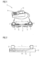
- Fig. 1 shows a principle view of the inventive apparatus 1 according to an exemplary embodiment of the invention.
- the apparatus 1 essentially comprises three components, i.e. an ultrasonic transducer 2, an ultrasonic receiver 3 and a control unit 4 communicating with both ultrasonic transducer 2 and the ultrasonic receiver 3 by means of cables or radio communication.
- the ultrasonic transducer 2 and the ultrasonic receiver 3 are disposed in a defined linear geometrical relationship by means of a connecting member 5 having the shape of a rod or a cable both of defined length 1.
- the ends of the connecting members 5 are provided with respective supports 6, 7 supporting the ultrasonic transducer 2 and the ultrasonic receiver 3 respectively.
- By actuating the respective levers 8, 9 it is possible to detach the ultrasonic transducer 2 and the ultrasonic receiver 3 from the connecting member 5.
- the ultrasonic transducer 2 is adapted to emit an ultrasonic signal 15 (ultrasonic wave), the ultrasonic receiver 3 is adapted to receive respective ultrasonic signals 15.
- the control unit 4 is adapted to generate at least one measurement signal from the received ultrasonic signal 15 and to determine an information indicating a degree of the fibre orientation in relation to the linear geometrical relationship of the ultrasonic transducer 2 and the ultrasonic receiver 3 from the at least one measurement signal.
- control unit 4 comprises a display 10 in order to output the respective information.
- the inventive apparatus 1 is relatively small in size and consequently easy to carry even when working on respective fibre-reinforced components 11 such as rotor blades or the like.
- the fibre-reinforced component 11 is built of a laminate material 12 such as a resin including a number of fibres 13 such as glass and/or carbon fibres for instance.
- the fibres 13 are orientated in one defined direction, i.e. the fibres 13 are uni-directionally orientated (cf. arrow 14 in fig. 3, 4 ).
- both the ultrasonic transducer 2 and the ultrasonic receiver 3 are disposed on the surface of the component 11. It is possible to apply a respective ultrasonic gel on the surface of the component 11 in order to improve the signal quality of the respective ultrasonic signals 15.
- the ultrasonic transducer 2 emits ultrasonic signals 15, i.e. ultrasonic waves of a given frequency of about 100 kHz into the component 11.
- the ultrasonic receiver 3 receives the reflected ultrasonic signals 15. Both emission and reception of the ultrasonic signals 15 is controlled by the control unit 4.
- the control unit 4 generates a measurement signal from the received ultrasonic signal 15.
- the measurement signal particularly includes the amplitude and/or the time of flight of the respective ultrasonic signal 15.
- the inventive method allows a qualitatively and non-destructive determination of the position and/or orientation of the respective fibres 13 within the component 11, though they are not visible from the outside.
- the connecting member 5 connecting the ultrasonic transducer 2 and the ultrasonic receiver 3 is disposed with a slight angle ⁇ relative to the orientation of the fibres 13 as indicated by arrow 14.
- the position and/or orientation of the connecting member 5 does not match the position and/or orientation of the fibres 13 as the connecting member 5 has an inclined position and/or orientation in relation to the fibres 13.
- the measurement signal is damped since the alignment of the connecting members 5, i.e. the ultrasonic transducer 2 and the ultrasonic receiver 3 does not match the orientation of the fibres 13.
- a first inventive information considering the amplitude and/or the time of flight of the received ultrasonic signal 15 is output by the control unit 4. Both the amplitude and the time of flight allow a qualitative correlation between the matching of the position and/or orientation of the ultrasonic transducer 2 and the ultrasonic receiver 3 in relation to the position and/or orientation of the fibres 13 within the component 11.
- the respective information will also change.
- the position and/or orientation of the ultrasonic transducer 2 and the ultrasonic receiver 3 essentially matches the position and/or orientation of the respective fibres 13 in fig. 4 . This is reflected in the amplitude and the time of flight of the received ultrasonic signal 15 and further in the respective information generated from the measurement signal since a respective alignment of the ultrasonic transducer 2 and the ultrasonic receiver 3 relative to the fibres 13 will essentially increase the amplitude and decrease the time of flight of the respective ultrasonic signal 15.
- the information generated in fig. 4 also differs from the respective information generated in fig. 3 .
- This may be perceivable by a respective text or graphical output on the display 10 of the control unit 4. Aside, it is thinkable that an audible information is output with higher volume or visual information is output with higher intensity in dependence of the degree of matched alignment of the ultrasonic transducer 2 and the ultrasonic receiver 3 relative to the respective fibres 13.
- the present invention is advantageous in that it solves the problem of determining the position and/or orientation of the fibres 13 in respective rotor blades of wind turbines 11.
- the inventive method is non-destructive and offers an easy and fast way to estimate the position and/or orientation of respective fibres 13 even when the fibres 13 are not visible from the outside due to coatings, surface paint, etc.
Landscapes
- Physics & Mathematics (AREA)
- Biochemistry (AREA)
- Health & Medical Sciences (AREA)
- Life Sciences & Earth Sciences (AREA)
- Chemical & Material Sciences (AREA)
- Analytical Chemistry (AREA)
- Acoustics & Sound (AREA)
- General Health & Medical Sciences (AREA)
- General Physics & Mathematics (AREA)
- Immunology (AREA)
- Pathology (AREA)
- Investigating Or Analyzing Materials By The Use Of Ultrasonic Waves (AREA)
- Wind Motors (AREA)
Claims (11)
- Verfahren zum Bestimmen der Faserausrichtung in einem Rotorblatt einer Windenergieanlage, bei dem in einem Laminatmaterial eine Anzahl Fasern verteilt sind, wobei die Fasern in mindestens einer festgelegten Richtung ausgerichtet sind, mit folgenden Schritten:a) Aussenden eines Ultraschallsignals in die Komponente mit Hilfe eines Ultraschallwandlers,b) Empfangen eines reflektierten Ultraschallsignals mit Hilfe eines Ultraschallempfängers und Erzeugen eines Messsignals, wobei der Ultraschallwandler und der Ultraschallempfänger in einer festgelegten linearen Beziehung angeordnet sind,c) Bestimmen einer Information, die einen Grad der Faserausrichtung in Bezug auf die festgelegte lineare Beziehung des Ultraschallwandlers und des Ultraschallempfängers angibt, aus dem entsprechenden Messsignal.
- Verfahren nach Anspruch 1, bei dem die Schritte a) und b) mindestens einmal wiederholt werden, während der Ultraschallwandler und/ oder der Ultraschallempfänger an der faserverstärkten Komponente entlang verschoben werden, wobei die entsprechende Information aus separaten entsprechenden Messsignalen oder allen entsprechenden Messsignalen bestimmt wird.
- Verfahren nach Anspruch 1 oder 2, bei dem die Information aus der Amplitude und/ oder der Laufzeit des empfangenen Ultraschallsignals bestimmt wird.
- Verfahren nach einem der vorhergehenden Ansprüche, bei dem das ausgesendete Ultraschallsignal eine Frequenz von 100 kHz besitzt.
- Verfahren nach einem der vorhergehenden Ansprüche, bei dem die Information als Audio- und/ oder visuelle Information ausgegeben wird.
- Verfahren nach einem der vorhergehenden Ansprüche, bei dem zumindest in dem Bereich des Ultraschallwandlers und des Ultraschallempfängers ein Ultraschallgel auf die Oberfläche der entsprechenden Komponente aufgetragen wird.
- Vorrichtung (1) zum Bestimmen der Faserausrichtung in einem Rotorblatt einer Windenergieanlage, bei dem in einem Laminatmaterial (12) eine Anzahl Fasern (13) verteilt sind, wobei die Fasern (13) in mindestens einer festgelegten Richtung ausgerichtet sind, wobei die Vorrichtung (1) Folgendes umfasst: mindestens einen Ultraschallwandler (2), der so ausgelegt ist, dass er ein Ultraschallsignal (15) aussendet, und mindestens einen Ultraschallempfänger (3), der so ausgelegt ist, dass er ein Ultraschallsignal (15) empfängt, wobei der Ultraschallwandler (2) und der Ultraschallempfänger (3) in einer festgelegten linearen Beziehung angeordnet sind, und eine Steuereinheit (4), die so ausgelegt ist, dass sie aus dem empfangenen Ultraschallsignal (15) mindestens ein Messsignal erzeugt und aus dem mindestens einen Messsignal eine Information bestimmt, die einen Grad der Faserausrichtung in Bezug auf die lineare geometrische Beziehung des Ultraschallwandlers (2) und des Ultraschallempfängers (3) angibt, wobei die Vorrichtung (1) so ausgelegt ist, dass sie das Verfahren nach einem der vorhergehenden Ansprüche ausführt, wobei der Ultraschallwandler (2) und der Ultraschallempfänger (3) über ein lineares Verbindungselement (5) verbunden sind, dadurch gekennzeichnet, dass die Länge des Verbindungselements (5) verstellbar ist.
- Vorrichtung nach Anspruch 7, bei der die Steuereinheit (4) so ausgelegt ist, dass sie die Information aus der Amplitude und/ oder der Laufzeit des empfangenen Ultraschallsignals (15) bestimmt.
- Vorrichtung nach Anspruch 7 oder 8, bei der der Ultraschallwandler (2) und/ oder der Ultraschallempfänger (3) lösbar mit dem Verbindungselement (5) verbunden sind.
- Vorrichtung nach einem der Ansprüche 7 bis 9, bei der die Steuereinheit (4) mindestens eine Benutzerschnittstelle umfasst, die so ausgelegt ist, dass sie die entsprechende Information als Audio- und/ oder visuelle Information ausgibt.
- Vorrichtung nach einem der Ansprüche 7 bis 10, bei der der Ultraschallwandler (2) so ausgelegt ist, dass er Ultraschallsignale mit einer Frequenz von 100 kHz aussendet.
Priority Applications (1)
| Application Number | Priority Date | Filing Date | Title |
|---|---|---|---|
| EP11728205.3A EP2633302B1 (de) | 2011-01-11 | 2011-06-08 | Verfahren zur bestimmung der faserorientierung bei einem rotorblatt einer windturbine mit einer anzahl von verteilten fasern in einem laminatmaterial |
Applications Claiming Priority (3)
| Application Number | Priority Date | Filing Date | Title |
|---|---|---|---|
| EP11150622 | 2011-01-11 | ||
| PCT/EP2011/059446 WO2012095189A1 (en) | 2011-01-11 | 2011-06-08 | Method for determining the fibre orientation in a fibre-reinforced component having a number of fibres distributed in a laminate material |
| EP11728205.3A EP2633302B1 (de) | 2011-01-11 | 2011-06-08 | Verfahren zur bestimmung der faserorientierung bei einem rotorblatt einer windturbine mit einer anzahl von verteilten fasern in einem laminatmaterial |
Publications (2)
| Publication Number | Publication Date |
|---|---|
| EP2633302A1 EP2633302A1 (de) | 2013-09-04 |
| EP2633302B1 true EP2633302B1 (de) | 2014-09-10 |
Family
ID=44474999
Family Applications (1)
| Application Number | Title | Priority Date | Filing Date |
|---|---|---|---|
| EP11728205.3A Active EP2633302B1 (de) | 2011-01-11 | 2011-06-08 | Verfahren zur bestimmung der faserorientierung bei einem rotorblatt einer windturbine mit einer anzahl von verteilten fasern in einem laminatmaterial |
Country Status (6)
| Country | Link |
|---|---|
| US (1) | US20130298681A1 (de) |
| EP (1) | EP2633302B1 (de) |
| CN (1) | CN103299185A (de) |
| DK (1) | DK2633302T3 (de) |
| NZ (1) | NZ611345A (de) |
| WO (1) | WO2012095189A1 (de) |
Cited By (1)
| Publication number | Priority date | Publication date | Assignee | Title |
|---|---|---|---|---|
| DE102021200690A1 (de) | 2021-01-27 | 2022-07-28 | Volkswagen Aktiengesellschaft | Verfahren, Computerprogrammprodukt und Vorrichtung zur Bestimmung eines Fasergehaltes, einer Faserverteilung und/oder einer Faserorientierung in einem faserverstärkten Bauteil |
Families Citing this family (3)
| Publication number | Priority date | Publication date | Assignee | Title |
|---|---|---|---|---|
| EP2933480A1 (de) * | 2014-04-15 | 2015-10-21 | Siemens Aktiengesellschaft | Überwachung der Laminierung einer Komponente einer Windturbine |
| DE102016202782A1 (de) * | 2016-02-23 | 2017-08-24 | Rud Ketten Rieger & Dietz Gmbh U. Co. Kg | Lastaufnehmendes Bauteil der Anschlag-, Zurr- und/oder Hebetechnik mit einem Kunststoff-Metall-Verbundsystem |
| CN108804852A (zh) * | 2018-06-28 | 2018-11-13 | 东汉新能源汽车技术有限公司 | 纤维定向的预测方法及装置 |
Family Cites Families (6)
| Publication number | Priority date | Publication date | Assignee | Title |
|---|---|---|---|---|
| SU830232A1 (ru) * | 1979-04-05 | 1981-05-15 | Предприятие П/Я М-5612 | Датчик дл измерени скоростиРАСпРОСТРАНЕНи ульТРАзВуКА B АНизО-ТРОпНыХ ВОлОКНиСТыХ МАТЕРиАлАХ |
| US5408882A (en) * | 1991-06-24 | 1995-04-25 | General Electric Company | Ultrasonic device and method for non-destructive evaluation of polymer composites |
| US6920790B2 (en) * | 2000-06-22 | 2005-07-26 | The Boeing Company | Apparatus for in-situ nondestructive measurement of Young's modulus of plate structures |
| DK175275B1 (da) * | 2002-03-19 | 2004-08-02 | Lm Glasfiber As | Overgangsområde i vindmöllevinge |
| FR2840991B1 (fr) * | 2002-06-17 | 2005-05-06 | Air Liquide | Procede de controle par ultrasons de joints soudes |
| US20040267121A1 (en) * | 2003-06-12 | 2004-12-30 | Sarvazyan Armen P. | Device and method for biopsy guidance using a tactile breast imager |
-
2011
- 2011-06-08 EP EP11728205.3A patent/EP2633302B1/de active Active
- 2011-06-08 NZ NZ611345A patent/NZ611345A/en not_active IP Right Cessation
- 2011-06-08 CN CN2011800647266A patent/CN103299185A/zh active Pending
- 2011-06-08 US US13/997,693 patent/US20130298681A1/en not_active Abandoned
- 2011-06-08 DK DK11728205.3T patent/DK2633302T3/da active
- 2011-06-08 WO PCT/EP2011/059446 patent/WO2012095189A1/en not_active Ceased
Cited By (1)
| Publication number | Priority date | Publication date | Assignee | Title |
|---|---|---|---|---|
| DE102021200690A1 (de) | 2021-01-27 | 2022-07-28 | Volkswagen Aktiengesellschaft | Verfahren, Computerprogrammprodukt und Vorrichtung zur Bestimmung eines Fasergehaltes, einer Faserverteilung und/oder einer Faserorientierung in einem faserverstärkten Bauteil |
Also Published As
| Publication number | Publication date |
|---|---|
| DK2633302T3 (da) | 2014-10-20 |
| US20130298681A1 (en) | 2013-11-14 |
| WO2012095189A1 (en) | 2012-07-19 |
| EP2633302A1 (de) | 2013-09-04 |
| CN103299185A (zh) | 2013-09-11 |
| NZ611345A (en) | 2015-07-31 |
Similar Documents
| Publication | Publication Date | Title |
|---|---|---|
| EP2633302B1 (de) | Verfahren zur bestimmung der faserorientierung bei einem rotorblatt einer windturbine mit einer anzahl von verteilten fasern in einem laminatmaterial | |
| CN101335573B (zh) | 一种水声信号发射机宽带自适应匹配方法及其装置 | |
| JP2008303882A5 (de) | ||
| KR101549534B1 (ko) | 선박용 레이더 장치 및 그 운용 방법 | |
| WO2007095935A3 (de) | Aerodynamisches profil für luftfahrzeuge und windkraftanlagen sowie verfahren zur messung der eisdicke auf einem aerodynamischen profil | |
| WO2009041513A1 (ja) | 放射電力測定方法、放射電力測定用結合器及び放射電力測定装置 | |
| CN104501938B (zh) | 一种在置于空气中的矩形混响水槽内测量水下声源低频辐射声功率的方法 | |
| CN104907240A (zh) | 一种换能器的弧形阵及制作方法 | |
| DK2855930T3 (en) | A method for the installation of sensors in the rotor blades and the installation device | |
| CN115144438B (zh) | 一种无线微带贴片天线传感器及在脱粘缺陷检测领域的应用 | |
| CN118191438A (zh) | 用于电磁环境监测的测试信号参数确定方法及系统 | |
| US10018600B2 (en) | System for non-destructive inspection of structural components | |
| CN116973847B (zh) | 俯仰反射式3d扫描雷达 | |
| CN116892490B (zh) | 风力发电机叶片的超声波除冰方法、控制器、系统及介质 | |
| AU2015246082B2 (en) | Method and assembly for inspecting a partially cured repair patch prior to installation | |
| CN220853504U (zh) | 俯仰反射式三维扫描装置 | |
| JP6354631B2 (ja) | 目付量測定方法 | |
| Rittmann et al. | A mobile nondestructive testing (NDT) system for fast detection of impact damage in fiber-reinforced plastics (FRP) | |
| CN102200095A (zh) | 一种风机运行方法、风速测量装置及风力发电机组 | |
| Tinney et al. | Optimum hover conditions for reduced noise from a notional eVTOL rotor | |
| CN107110117A (zh) | 涉及风力涡轮机的改进 | |
| JP2005221324A (ja) | ひずみ計測装置及び計測方法 | |
| CN107064917A (zh) | 一种微波定位方法及系统 | |
| Zhao et al. | Design of surface acoustic wave parafoil riser tension sensor | |
| CN119532131B (zh) | 风电叶片螺栓的旋入监测装置 |
Legal Events
| Date | Code | Title | Description |
|---|---|---|---|
| PUAI | Public reference made under article 153(3) epc to a published international application that has entered the european phase |
Free format text: ORIGINAL CODE: 0009012 |
|
| 17P | Request for examination filed |
Effective date: 20130531 |
|
| AK | Designated contracting states |
Kind code of ref document: A1 Designated state(s): AL AT BE BG CH CY CZ DE DK EE ES FI FR GB GR HR HU IE IS IT LI LT LU LV MC MK MT NL NO PL PT RO RS SE SI SK SM TR |
|
| GRAP | Despatch of communication of intention to grant a patent |
Free format text: ORIGINAL CODE: EPIDOSNIGR1 |
|
| DAX | Request for extension of the european patent (deleted) | ||
| INTG | Intention to grant announced |
Effective date: 20140320 |
|
| GRAS | Grant fee paid |
Free format text: ORIGINAL CODE: EPIDOSNIGR3 |
|
| GRAA | (expected) grant |
Free format text: ORIGINAL CODE: 0009210 |
|
| AK | Designated contracting states |
Kind code of ref document: B1 Designated state(s): AL AT BE BG CH CY CZ DE DK EE ES FI FR GB GR HR HU IE IS IT LI LT LU LV MC MK MT NL NO PL PT RO RS SE SI SK SM TR |
|
| REG | Reference to a national code |
Ref country code: GB Ref legal event code: FG4D |
|
| REG | Reference to a national code |
Ref country code: CH Ref legal event code: EP |
|
| REG | Reference to a national code |
Ref country code: IE Ref legal event code: FG4D |
|
| REG | Reference to a national code |
Ref country code: AT Ref legal event code: REF Ref document number: 686948 Country of ref document: AT Kind code of ref document: T Effective date: 20141015 |
|
| REG | Reference to a national code |
Ref country code: DK Ref legal event code: T3 Effective date: 20141013 |
|
| REG | Reference to a national code |
Ref country code: DE Ref legal event code: R096 Ref document number: 602011009803 Country of ref document: DE Effective date: 20141023 |
|
| PG25 | Lapsed in a contracting state [announced via postgrant information from national office to epo] |
Ref country code: SE Free format text: LAPSE BECAUSE OF FAILURE TO SUBMIT A TRANSLATION OF THE DESCRIPTION OR TO PAY THE FEE WITHIN THE PRESCRIBED TIME-LIMIT Effective date: 20140910 Ref country code: FI Free format text: LAPSE BECAUSE OF FAILURE TO SUBMIT A TRANSLATION OF THE DESCRIPTION OR TO PAY THE FEE WITHIN THE PRESCRIBED TIME-LIMIT Effective date: 20140910 Ref country code: LT Free format text: LAPSE BECAUSE OF FAILURE TO SUBMIT A TRANSLATION OF THE DESCRIPTION OR TO PAY THE FEE WITHIN THE PRESCRIBED TIME-LIMIT Effective date: 20140910 Ref country code: GR Free format text: LAPSE BECAUSE OF FAILURE TO SUBMIT A TRANSLATION OF THE DESCRIPTION OR TO PAY THE FEE WITHIN THE PRESCRIBED TIME-LIMIT Effective date: 20141211 Ref country code: ES Free format text: LAPSE BECAUSE OF FAILURE TO SUBMIT A TRANSLATION OF THE DESCRIPTION OR TO PAY THE FEE WITHIN THE PRESCRIBED TIME-LIMIT Effective date: 20140910 Ref country code: NO Free format text: LAPSE BECAUSE OF FAILURE TO SUBMIT A TRANSLATION OF THE DESCRIPTION OR TO PAY THE FEE WITHIN THE PRESCRIBED TIME-LIMIT Effective date: 20141210 |
|
| REG | Reference to a national code |
Ref country code: NL Ref legal event code: VDEP Effective date: 20140910 |
|
| REG | Reference to a national code |
Ref country code: LT Ref legal event code: MG4D |
|
| PG25 | Lapsed in a contracting state [announced via postgrant information from national office to epo] |
Ref country code: CY Free format text: LAPSE BECAUSE OF FAILURE TO SUBMIT A TRANSLATION OF THE DESCRIPTION OR TO PAY THE FEE WITHIN THE PRESCRIBED TIME-LIMIT Effective date: 20140910 Ref country code: RS Free format text: LAPSE BECAUSE OF FAILURE TO SUBMIT A TRANSLATION OF THE DESCRIPTION OR TO PAY THE FEE WITHIN THE PRESCRIBED TIME-LIMIT Effective date: 20140910 Ref country code: LV Free format text: LAPSE BECAUSE OF FAILURE TO SUBMIT A TRANSLATION OF THE DESCRIPTION OR TO PAY THE FEE WITHIN THE PRESCRIBED TIME-LIMIT Effective date: 20140910 Ref country code: HR Free format text: LAPSE BECAUSE OF FAILURE TO SUBMIT A TRANSLATION OF THE DESCRIPTION OR TO PAY THE FEE WITHIN THE PRESCRIBED TIME-LIMIT Effective date: 20140910 |
|
| REG | Reference to a national code |
Ref country code: AT Ref legal event code: MK05 Ref document number: 686948 Country of ref document: AT Kind code of ref document: T Effective date: 20140910 |
|
| PG25 | Lapsed in a contracting state [announced via postgrant information from national office to epo] |
Ref country code: NL Free format text: LAPSE BECAUSE OF FAILURE TO SUBMIT A TRANSLATION OF THE DESCRIPTION OR TO PAY THE FEE WITHIN THE PRESCRIBED TIME-LIMIT Effective date: 20140910 |
|
| PG25 | Lapsed in a contracting state [announced via postgrant information from national office to epo] |
Ref country code: SK Free format text: LAPSE BECAUSE OF FAILURE TO SUBMIT A TRANSLATION OF THE DESCRIPTION OR TO PAY THE FEE WITHIN THE PRESCRIBED TIME-LIMIT Effective date: 20140910 Ref country code: CZ Free format text: LAPSE BECAUSE OF FAILURE TO SUBMIT A TRANSLATION OF THE DESCRIPTION OR TO PAY THE FEE WITHIN THE PRESCRIBED TIME-LIMIT Effective date: 20140910 Ref country code: PT Free format text: LAPSE BECAUSE OF FAILURE TO SUBMIT A TRANSLATION OF THE DESCRIPTION OR TO PAY THE FEE WITHIN THE PRESCRIBED TIME-LIMIT Effective date: 20150112 Ref country code: RO Free format text: LAPSE BECAUSE OF FAILURE TO SUBMIT A TRANSLATION OF THE DESCRIPTION OR TO PAY THE FEE WITHIN THE PRESCRIBED TIME-LIMIT Effective date: 20140910 Ref country code: IS Free format text: LAPSE BECAUSE OF FAILURE TO SUBMIT A TRANSLATION OF THE DESCRIPTION OR TO PAY THE FEE WITHIN THE PRESCRIBED TIME-LIMIT Effective date: 20150110 Ref country code: EE Free format text: LAPSE BECAUSE OF FAILURE TO SUBMIT A TRANSLATION OF THE DESCRIPTION OR TO PAY THE FEE WITHIN THE PRESCRIBED TIME-LIMIT Effective date: 20140910 |
|
| PG25 | Lapsed in a contracting state [announced via postgrant information from national office to epo] |
Ref country code: PL Free format text: LAPSE BECAUSE OF FAILURE TO SUBMIT A TRANSLATION OF THE DESCRIPTION OR TO PAY THE FEE WITHIN THE PRESCRIBED TIME-LIMIT Effective date: 20140910 Ref country code: AT Free format text: LAPSE BECAUSE OF FAILURE TO SUBMIT A TRANSLATION OF THE DESCRIPTION OR TO PAY THE FEE WITHIN THE PRESCRIBED TIME-LIMIT Effective date: 20140910 |
|
| REG | Reference to a national code |
Ref country code: DE Ref legal event code: R097 Ref document number: 602011009803 Country of ref document: DE |
|
| PLBE | No opposition filed within time limit |
Free format text: ORIGINAL CODE: 0009261 |
|
| STAA | Information on the status of an ep patent application or granted ep patent |
Free format text: STATUS: NO OPPOSITION FILED WITHIN TIME LIMIT |
|
| 26N | No opposition filed |
Effective date: 20150611 |
|
| PG25 | Lapsed in a contracting state [announced via postgrant information from national office to epo] |
Ref country code: IT Free format text: LAPSE BECAUSE OF FAILURE TO SUBMIT A TRANSLATION OF THE DESCRIPTION OR TO PAY THE FEE WITHIN THE PRESCRIBED TIME-LIMIT Effective date: 20140910 |
|
| PG25 | Lapsed in a contracting state [announced via postgrant information from national office to epo] |
Ref country code: SI Free format text: LAPSE BECAUSE OF FAILURE TO SUBMIT A TRANSLATION OF THE DESCRIPTION OR TO PAY THE FEE WITHIN THE PRESCRIBED TIME-LIMIT Effective date: 20140910 |
|
| PG25 | Lapsed in a contracting state [announced via postgrant information from national office to epo] |
Ref country code: MC Free format text: LAPSE BECAUSE OF FAILURE TO SUBMIT A TRANSLATION OF THE DESCRIPTION OR TO PAY THE FEE WITHIN THE PRESCRIBED TIME-LIMIT Effective date: 20140910 |
|
| REG | Reference to a national code |
Ref country code: CH Ref legal event code: PL |
|
| PG25 | Lapsed in a contracting state [announced via postgrant information from national office to epo] |
Ref country code: LU Free format text: LAPSE BECAUSE OF FAILURE TO SUBMIT A TRANSLATION OF THE DESCRIPTION OR TO PAY THE FEE WITHIN THE PRESCRIBED TIME-LIMIT Effective date: 20150608 |
|
| REG | Reference to a national code |
Ref country code: IE Ref legal event code: MM4A |
|
| REG | Reference to a national code |
Ref country code: FR Ref legal event code: ST Effective date: 20160229 |
|
| PG25 | Lapsed in a contracting state [announced via postgrant information from national office to epo] |
Ref country code: IE Free format text: LAPSE BECAUSE OF NON-PAYMENT OF DUE FEES Effective date: 20150608 Ref country code: CH Free format text: LAPSE BECAUSE OF NON-PAYMENT OF DUE FEES Effective date: 20150630 Ref country code: LI Free format text: LAPSE BECAUSE OF NON-PAYMENT OF DUE FEES Effective date: 20150630 |
|
| PG25 | Lapsed in a contracting state [announced via postgrant information from national office to epo] |
Ref country code: FR Free format text: LAPSE BECAUSE OF NON-PAYMENT OF DUE FEES Effective date: 20150630 |
|
| PG25 | Lapsed in a contracting state [announced via postgrant information from national office to epo] |
Ref country code: BE Free format text: LAPSE BECAUSE OF FAILURE TO SUBMIT A TRANSLATION OF THE DESCRIPTION OR TO PAY THE FEE WITHIN THE PRESCRIBED TIME-LIMIT Effective date: 20140910 |
|
| PG25 | Lapsed in a contracting state [announced via postgrant information from national office to epo] |
Ref country code: MT Free format text: LAPSE BECAUSE OF FAILURE TO SUBMIT A TRANSLATION OF THE DESCRIPTION OR TO PAY THE FEE WITHIN THE PRESCRIBED TIME-LIMIT Effective date: 20140910 |
|
| PG25 | Lapsed in a contracting state [announced via postgrant information from national office to epo] |
Ref country code: SM Free format text: LAPSE BECAUSE OF FAILURE TO SUBMIT A TRANSLATION OF THE DESCRIPTION OR TO PAY THE FEE WITHIN THE PRESCRIBED TIME-LIMIT Effective date: 20140910 Ref country code: HU Free format text: LAPSE BECAUSE OF FAILURE TO SUBMIT A TRANSLATION OF THE DESCRIPTION OR TO PAY THE FEE WITHIN THE PRESCRIBED TIME-LIMIT; INVALID AB INITIO Effective date: 20110608 Ref country code: BG Free format text: LAPSE BECAUSE OF FAILURE TO SUBMIT A TRANSLATION OF THE DESCRIPTION OR TO PAY THE FEE WITHIN THE PRESCRIBED TIME-LIMIT Effective date: 20140910 |
|
| PG25 | Lapsed in a contracting state [announced via postgrant information from national office to epo] |
Ref country code: TR Free format text: LAPSE BECAUSE OF FAILURE TO SUBMIT A TRANSLATION OF THE DESCRIPTION OR TO PAY THE FEE WITHIN THE PRESCRIBED TIME-LIMIT Effective date: 20140910 |
|
| PG25 | Lapsed in a contracting state [announced via postgrant information from national office to epo] |
Ref country code: MK Free format text: LAPSE BECAUSE OF FAILURE TO SUBMIT A TRANSLATION OF THE DESCRIPTION OR TO PAY THE FEE WITHIN THE PRESCRIBED TIME-LIMIT Effective date: 20140910 |
|
| PG25 | Lapsed in a contracting state [announced via postgrant information from national office to epo] |
Ref country code: AL Free format text: LAPSE BECAUSE OF FAILURE TO SUBMIT A TRANSLATION OF THE DESCRIPTION OR TO PAY THE FEE WITHIN THE PRESCRIBED TIME-LIMIT Effective date: 20140910 |
|
| REG | Reference to a national code |
Ref country code: DE Ref legal event code: R081 Ref document number: 602011009803 Country of ref document: DE Owner name: SIEMENS GAMESA RENEWABLE ENERGY A/S, DK Free format text: FORMER OWNER: SIEMENS AKTIENGESELLSCHAFT, 80333 MUENCHEN, DE |
|
| REG | Reference to a national code |
Ref country code: GB Ref legal event code: 732E Free format text: REGISTERED BETWEEN 20191128 AND 20191204 |
|
| PGFP | Annual fee paid to national office [announced via postgrant information from national office to epo] |
Ref country code: DE Payment date: 20250626 Year of fee payment: 15 |
|
| PGFP | Annual fee paid to national office [announced via postgrant information from national office to epo] |
Ref country code: GB Payment date: 20250617 Year of fee payment: 15 Ref country code: DK Payment date: 20250619 Year of fee payment: 15 |