EP2632768B1 - Steering device for motor vehicles - Google Patents
Steering device for motor vehicles Download PDFInfo
- Publication number
- EP2632768B1 EP2632768B1 EP11757309.7A EP11757309A EP2632768B1 EP 2632768 B1 EP2632768 B1 EP 2632768B1 EP 11757309 A EP11757309 A EP 11757309A EP 2632768 B1 EP2632768 B1 EP 2632768B1
- Authority
- EP
- European Patent Office
- Prior art keywords
- steering
- steering wheel
- conductor
- end module
- tubes
- Prior art date
- Legal status (The legal status is an assumption and is not a legal conclusion. Google has not performed a legal analysis and makes no representation as to the accuracy of the status listed.)
- Not-in-force
Links
Images


Classifications
-
- B—PERFORMING OPERATIONS; TRANSPORTING
- B62—LAND VEHICLES FOR TRAVELLING OTHERWISE THAN ON RAILS
- B62D—MOTOR VEHICLES; TRAILERS
- B62D1/00—Steering controls, i.e. means for initiating a change of direction of the vehicle
- B62D1/02—Steering controls, i.e. means for initiating a change of direction of the vehicle vehicle-mounted
- B62D1/16—Steering columns
- B62D1/18—Steering columns yieldable or adjustable, e.g. tiltable
- B62D1/185—Steering columns yieldable or adjustable, e.g. tiltable adjustable by axial displacement, e.g. telescopically
-
- B—PERFORMING OPERATIONS; TRANSPORTING
- B60—VEHICLES IN GENERAL
- B60R—VEHICLES, VEHICLE FITTINGS, OR VEHICLE PARTS, NOT OTHERWISE PROVIDED FOR
- B60R16/00—Electric or fluid circuits specially adapted for vehicles and not otherwise provided for; Arrangement of elements of electric or fluid circuits specially adapted for vehicles and not otherwise provided for
- B60R16/02—Electric or fluid circuits specially adapted for vehicles and not otherwise provided for; Arrangement of elements of electric or fluid circuits specially adapted for vehicles and not otherwise provided for electric constitutive elements
- B60R16/023—Electric or fluid circuits specially adapted for vehicles and not otherwise provided for; Arrangement of elements of electric or fluid circuits specially adapted for vehicles and not otherwise provided for electric constitutive elements for transmission of signals between vehicle parts or subsystems
- B60R16/027—Electric or fluid circuits specially adapted for vehicles and not otherwise provided for; Arrangement of elements of electric or fluid circuits specially adapted for vehicles and not otherwise provided for electric constitutive elements for transmission of signals between vehicle parts or subsystems between relatively movable parts of the vehicle, e.g. between steering wheel and column
-
- B—PERFORMING OPERATIONS; TRANSPORTING
- B62—LAND VEHICLES FOR TRAVELLING OTHERWISE THAN ON RAILS
- B62D—MOTOR VEHICLES; TRAILERS
- B62D1/00—Steering controls, i.e. means for initiating a change of direction of the vehicle
- B62D1/02—Steering controls, i.e. means for initiating a change of direction of the vehicle vehicle-mounted
- B62D1/16—Steering columns
-
- B—PERFORMING OPERATIONS; TRANSPORTING
- B62—LAND VEHICLES FOR TRAVELLING OTHERWISE THAN ON RAILS
- B62D—MOTOR VEHICLES; TRAILERS
- B62D65/00—Designing, manufacturing, e.g. assembling, facilitating disassembly, or structurally modifying motor vehicles or trailers, not otherwise provided for
-
- Y—GENERAL TAGGING OF NEW TECHNOLOGICAL DEVELOPMENTS; GENERAL TAGGING OF CROSS-SECTIONAL TECHNOLOGIES SPANNING OVER SEVERAL SECTIONS OF THE IPC; TECHNICAL SUBJECTS COVERED BY FORMER USPC CROSS-REFERENCE ART COLLECTIONS [XRACs] AND DIGESTS
- Y10—TECHNICAL SUBJECTS COVERED BY FORMER USPC
- Y10T—TECHNICAL SUBJECTS COVERED BY FORMER US CLASSIFICATION
- Y10T29/00—Metal working
- Y10T29/49—Method of mechanical manufacture
- Y10T29/49002—Electrical device making
- Y10T29/49117—Conductor or circuit manufacturing
Definitions
- the invention relates to a steering device for a motor vehicle, according to the preamble of the first claim, with a steering wheel which is non-rotatably connected to a continuous hollow steering shaft through which at least one electrical conductor for electrical connection steering wheel-side control devices is performed.
- this relates to a steering device of the flexible Steering Concept, FSC type, without mechanical drive between a steering wheel and a steering gear, with a hydraulic fallback level from a coupled to the steering hydraulic winninger unit, and a coupled to the steering gear hydraulic Actuator over which in case of failure, a predetermined over the steering wheel steering wheel can be produced.
- FSC type flexible Steering Concept
- a steering device according to the preamble of the first claim is described in German Utility Model no. 1 698 768 disclosed.
- FSC systems in which the driver of a vehicle on the steering wheel or the like (instead of a steering wheel can also be a so-called.
- Steering column or steering shaft, as well as a coupled steering gear (eg rack and pinion steering gear) is transmitted, but on electric or hydraulic way, are the arrangement options for the system components in the vehicle advantageous.
- a so-called fallback level is provided, which is designed to be hydraulically flexible with respect to a desired space flexibility and the the features, coupled to the steering wheel hydraulic delivery unit, and coupled to said steering gear hydraulic actuator, and a hydraulic unit interconnecting these two units hydraulic circuit has.
- an FSC system requires a so-called steering torque simulator, by means of which a steering torque applied to the steering wheel can be applied counter to the steering wheel in order to give the driver a usual steering feel and thus virtually a haptic contact with the road.
- a steering torque simulator by means of which a steering torque applied to the steering wheel can be applied counter to the steering wheel in order to give the driver a usual steering feel and thus virtually a haptic contact with the road.
- an end stop for the rotational movement of the steering wheel is provided, which corresponds to the maximum steering angle of the steerable vehicle wheels.
- This end stop is usually represented by the mentioned steering torque simulator by an electric motor forming this reaching the end stop applies such a high counter torque to the steering torque applied by the driver to the steering wheel, that the driver can not turn the steering wheel further.
- the prior art also includes flexible conductor tracks, highly flexible cables and flat conductor strap lines, which have already proven themselves between moving elements with electrical connections as flexible transmission means for electricity.
- the content of DE 10 2005 016 676 A1 and EP 1 713 096 B1 Describe such conductors should, therefore, in the extent necessary for the invention belonging to the known prior art, also apply here as disclosed.
- the electrical conductor in the DE 199 00 083 A1 not surrounded by a separate protective device.
- the protective device and baffle of the steering wheel do not turn when steering, but only the steering wheel rim with the steering shaft.
- Steering wheel rim and steering wheel pot with protective device are rotated by a bearing 21 against each other, so that when steering turns only the steering wheel rim and thus the electrical conductor is subjected to no distortion.
- a steering device for a motor vehicle with a steering wheel which is non-rotatably connected to a continuous hollow steering shaft through which at least one electrical conductor for electrical connection steering wheel side equipment is guided, wherein the conductor is guided in the axial direction through the entire steering shaft, at both ends of the steering shaft exits therefrom, is substantially surrounded by a protective device, is held at the steering wheel-remote end of the protective device by an end module not rotating with the steering shaft and at the end of the protective device by a steering shaft with rotating, further end module is held, characterized in that the protective device is variable in length by telescopically extending and retracting, by telescoping from an outer and an inner two, each with its adjacent end, in the axial direction into one another stored protective tubes and that, the tubes of the protective device in axialer and in the circumferential direction, friction and / or form-fitting are fixed to each other.
- the length-adjustable protective device is easy to design and manufacture, for example made of plastic.
- a preassembled structural unit can consist of at least one end module, a further end module, the conductor with electrical connectors and the protective device connecting the end modules, of two telescopically telescoping telescoping in the axial direction, by a rotation and displacement securing each other pipes.
- the tubes of the protective device can be frictionally and / or positively fixed to one another, for example by a bayonet closure or by a serration in the circumferential direction, combined with at least one locking cam, in particular a locking collar, in the axial direction. If the frictional and / or positive connection of the tubes of the protective device is manually detachable at least from a steering wheel end of a pipe, this has the advantage that the assembly or disassembly of the central cable unit in the steering column due to the possibility of locking particularly simple and easily repeats executable is.
- the twistable length of the conductor can be chosen to be greater than the length of the steering shaft by the length of the conductor between the two end modules is greater than their distance from each other. This can be achieved in that the conductor in the axial direction at least within the steering shaft spiral and / or wavy and / or accordion-shaped and / or helical and / or band-shaped, and / or is designed as a single cable.
- About the end modules of the conductor can be fixed in the closed protective housing in a simple manner in its position. It is for connecting the conductor with its corresponding terminals on the steering wheel and the vehicle side advantageous if at the ends of the conductor line connectors are mounted. These can be connectors.
- a plurality of conductors may be electrically isolated from one another on a conductor carrier and this may be designed, for example, as a flexible conductor strip and / or highly flexible and / or flat conductor ribbon cable. It can also be more such conductor support with electrically insulated conductors together at least in the steering shaft, for example, one above the other, housed. It is advantageous if one or both end modules define the conductor or the conductor carrier at least in the axial direction, but in particular also in the radial direction.
- a steering device which is characterized in that it has no mechanical drive connection between the steering wheel and a steering gear, in particular when the steering gear is acted upon by an output signals from the steering wheel actuated actuator, such an arrangement of at least one conductor in the steering shaft is particularly of Advantage.
- FSC Flexible Steering Concept
- a unit is designed preassembled, at least consisting of end module, further end module, protective device and conductor, in particular with connectors. From preassembled state in the mounted state in the motor vehicle then such a unit is to be converted readily if it has the rotation, the position of the end module to that of the other end module at least in the twisting direction and in particular substantially in a middle position, based on a torsional of the conductor in both directions, a straight-ahead position of the steering wheel, determines. This middle position ensures that the ladder can be turned in both directions with the steering wheel until it stops.
- the two tubes can be fixed to each other in the circumferential direction.
- the electrical connection connections be automatically generated when attaching by the connector vehicle or steering wheel side make the connection from the conductor to the terminals in the vehicle or steering wheel, especially when introducing the preassembled unit into the steering shaft when the end module is fixed to the vehicle and when attaching the steering wheel, when the other end module is rotatably connected to the steering shaft.
- Particular embodiments of the method may advantageously include individual subject features of the invention, as explained above.
- a particularly advantageous method is for example in that the electrical connectors on the vehicle are fixed to the corresponding electrical connectors on the end module of the preassembled unit in such a way that their electrical connection is made simultaneously with the production of the positive connection on the end module during insertion of the preassembled unit into the hollow steering shaft.
- FIG. 1 an embodiment of a FSC steering according to the prior art, equipped with a steering shaft according to the prior art.
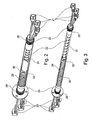
- the interior of a hollow steering shaft of a steering device according to the invention, a central cable unit, inter alia for use in a FSC steering, is in the FIGS. 2 to 4 in two embodiments, shown spatially and partially in different scales.
- the FIGS. 5 to 7 show partial enlargements FIG. 4 , the second embodiment.
- Like elements are designated by the same reference numerals.
- FIG. 1 is a steering system without mechanical drive connection between a steering wheel 1 and a steering gear 2, which is acted upon by an output signals from the steering wheel actuated actuator 3 and which is coupled to a hydraulic actuator 4, which is controlled by a steering wheel 1 controlled by the hydraulic feed unit. 5 is acted upon and via a switchable in the hydraulic circuit 6 hydraulic connection between the hydraulic conveying unit 5 and the hydraulic actuator 4 is a fallback to the steering operation in case of failure of the actuator 3.
- the steering wheel 1 to be operated by a driver of a vehicle is rotationally connected to a steering shaft 7 '.
- This is equipped with a rotation angle sensor 8, with which the driver with his steering wheel. 1 predetermined steering angle can be detected.
- an acting on the steering shaft 7 steering torque simulator 9 is designed as an electric motor.
- the hydraulic conveying unit 5 is provided in the form of a synchronous cylinder-piston unit.
- the two steerable wheels 11 of the two-lane vehicle are pivoted in a basically known manner via toggle lever and tie rods 12 and thus steerable, these tie rods 12 are articulated to a transversely displaceable to the vehicle longitudinal piston rod 14 of the steering gear 2.
- This steering gear 2 is actuated or acted upon by means of the electromotive actuator 3 such that the desired pivoting movement of the steerable wheels 11 is initiated.
- said actuator 3 more precisely an electric motor thereof, is controlled by an electronic control unit 13 on the basis of the signals of the rotation angle sensor 8 connected to the steering wheel 1, which reproduces a steering input of the driver.
- the electronic control unit 13 the position of the piston rod 14 of the steering gear 2 is transmitted.
- the vehicle must continue to be steerable, what a so-called fallback, is provided, inter alia, by the already mentioned steering wheel side part 10 of a hydraulic circuit 6, as well as a so-called fail-safe Valve 15 is formed with this suitably connectable steering gear side part 16 of the hydraulic circuit 6, which in turn acts on the hydraulic actuator 4, which is formed by the steering gear 2 itself. It may be the steering gear side Part 16 of the hydraulic circuit 6 via the hydraulic actuator 4 act on the steering gear 2 such that upon connection of the steering wheel side part 10 with the steering gear side part 16 of said hydraulic circuit 6, the steerable wheels 11 are steered according to the steering input on the steering wheel 1.
- the two parts 10, 16 of the hydraulic circuit 6 can be suitably connected to one another via the fail-safe valve 15, wherein the fail-safe valve 15 is designed such that it is in the non-energized state the connection between the two parts 10, 16 of the hydraulic circuit 6 and thus also establishes a hydraulic connection between the hydraulic conveying unit 5 and the hydraulic adjusting unit 4.
- the electrical connectors on the vehicle may be fixed to the corresponding electrical connectors 25 on the end module 23 of the preassembled unit so that their electrical connection coincides with the production of the positive connection on the end module 23 is automatically produced during insertion of the preassembled unit in the hollow steering shaft.
- the production of positive engagement is ever a toothing 26 or 26 'as a radial rotation on the end module 23 and the other end module 24 with a corresponding counter toothing on the vehicle side or steering wheel side during assembly of the central cable unit into engagement.
- the lines 22 are each surrounded by a permanently connected to the end module 23 and the other end module 24 tube 30 and another tube 31, which are inserted during assembly as part of the central cable unit from the steering wheel side into the steering shaft.
- the electrical connector 25, which is attached to the steering wheel-remote end of the conductor can therefore be designed and / or held fixed in the end module 23, at least in the axial direction, that with a corresponding electrical connector on the vehicle during assembly of the end module 23 automatically electrical connection is made. This can also be done by a self-locating direct insertion mechanism. This results in a simplification of the assembly and disassembly process, so an improvement in serviceability.
- the steering wheel 1 when twisting the lines 22 so twisted or deflects, they are chosen longer, so that the length of the lines 22 between the two end modules 23, 24 is greater than their distance from each other.
- the lines as flexible conductor tracks and / or highly flexible cables and / or flat conductor strap lines 22 spiral ( Fig. 2-7 ) and / or as not shown, corrugated and / or accordion-shaped and / or helical and / or band-shaped and / or designed as a single cable.
- FIGS. 2 to 4 each show a pre-assembled unit for a steering device for a motor vehicle with a steering wheel, not shown, which is non-rotatably connected to a non-illustrated continuous hollow steering shaft, are guided by the axial direction of electrical lines as flat conductor strap lines 22 for connecting steering wheel side equipment, the flat conductor strap lines 22 at both ends of the steering shaft from this end modules 23, 24 emerge and are substantially surrounded by a protective device, consisting of two protective tubes 30, 31 which are variable in length in the axial direction, by telescopically extending and retracting the two, each with its adjoining end slidably mounted tubes 30, 31. These are in axialer and in the circumferential direction in the axially fully extended position, positively fixed to one another.
- a protective device consisting of two protective tubes 30, 31 which are variable in length in the axial direction, by telescopically extending and retracting the two, each with its adjoining end slidably mounted tubes 30, 31.
- FIG. 2 and 3 show to the bayonet lock 32 as rotation, the position of the tubes 30, 31 to each other and thus the position of the end module 23 to that of the further end module 24 in the axial direction completely extended and sets in the direction of rotation substantially in a central position.
- FIG. 3 shown, the locking of the bayonet lock 32 in a transport position, telescopically completely extended in the axial direction, secured by a compression spring 29, which maintains the positive connection of the bayonet lock 32 by bracing the two tubes 30, 31 against each other.
- FIG. 2 showing a mounting position of the central cable unit, the bayonet lock 32 is unlocked and the compression spring 29 is more compressed by the installation in the steering shaft.
- the installation of the lines 22 is ensured in a defined middle position, from which the steering wheel can be turned to each side to the steering stop without affecting the lines 22 over the life of the motor vehicle in their function.
- FIGS. 4 . 6 and 7 show the transport position, the two tubes 30, 31 in the axial direction completely extended and fixed to each other, even in the circumferential direction, while in FIG. 5 a mounting position is shown, the tubes 30, 31 pushed together slightly axially and thereby unlocked in the axial and circumferential direction from each other and against each other.
- the central cable unit can now telescope.
- the central cable unit slides together in the same way. The dismantling of the central cable unit is carried out by the tube 31 is pulled steering wheel side of the steering column in the axial direction.
Description
Die Erfindung betrifft eine Lenkeinrichtung für ein Kraftfahrzeug, nach dem Oberbegriff des ersten Anspruchs, mit einem Lenkrad, das drehfest mit einer durchgehend hohlen Lenkwelle verbunden ist, durch die mindestens ein elektrischer Leiter zur elektrischen Anbindung lenkradseitiger Steuereinrichtungen geführt ist. Insbesondere betrifft dies eine Lenkeinrichtung der Flexible-Steering-Concept, FSC-Bauart, ohne mechanischen Durchtrieb zwischen einem Lenkrad und einem Lenkgetriebe, mit einer hydraulischen Rückfallebene aus einer an das Lenkrad gekoppelten Hydraulik-Förderein-heit, sowie einer an das Lenkgetriebe gekoppelten Hydraulik-Stelleinheit, über welche im Versagensfall auch ein über das Lenkrad vorgegebener Rad-Lenkeinschlag hergestellt werden kann. Zum bekannten Stand der Technik, was die FSC-Bauart betrifft, wird auf die
Die sogenannten FSC-Systeme, bei denen der vom Fahrer eines Fahrzeugs am Lenkrad oder dergleichen (anstelle eines Lenkrads kann auch ein sog. Sidestick oder anderes als Lenkhandhabe vorgesehen sein - im Weiteren wird der Einfachheit halber nur vom Lenkrad gesprochen) eingestellte Lenkwunsch den lenkbaren Fahrzeugrädern nicht auf direktem mechanischen Wege, nämlich wie im oben genannten Gebrauchsmuster und bei den heute üblichen Fahrzeugen, und über die sog. Lenksäule oder Lenkwelle, sowie ein daran gekoppeltes Lenkgetriebe (bspw. Zahnstangenlenkgetriebe) übermittelt wird, sondern auf elektrischem oder hydraulischem Weg, sind hinsichtlich der Anordnungsmöglichkeiten für die Systembestandteile im Fahrzeug vorteilhaft. Da jedoch ein Aktuator, der, angesteuert von Signalen der Lenkradvorgabe, die lenkbaren Räder verschwenkt, ausfallen kann, ist eine sogenannte Rückfallebene vorzusehen, welche im Hinblick auf eine erwünschte Bauraum-Flexibilität zumeist hydraulisch ausgebildet ist und die die Merkmale, eine an das Lenkrad gekoppelte Hydraulik-Fördereinheit, sowie eine an das genannte Lenkgetriebe gekoppelte Hydraulik-Stelleinheit, sowie einen diese beiden Einheiten hydraulisch miteinander verbindenden Hydraulikkreis, aufweist.The so-called FSC systems, in which the driver of a vehicle on the steering wheel or the like (instead of a steering wheel can also be a so-called. Sidestick or otherwise be provided as a steering handle - hereinafter, for the sake of simplicity only spoken by the steering wheel) set steering request the steerable vehicle wheels not in a direct mechanical way, namely as in the above-mentioned utility model and in today's conventional vehicles, and on the so-called. Steering column or steering shaft, as well as a coupled steering gear (eg rack and pinion steering gear) is transmitted, but on electric or hydraulic way, are the arrangement options for the system components in the vehicle advantageous. However, since an actuator which, driven by signals of the steering wheel default, the steerable wheels can turn out, a so-called fallback level is provided, which is designed to be hydraulically flexible with respect to a desired space flexibility and the the features, coupled to the steering wheel hydraulic delivery unit, and coupled to said steering gear hydraulic actuator, and a hydraulic unit interconnecting these two units hydraulic circuit has.
Weiterhin benötigt ein FSC-System einen sogenannten Lenkmoment-Simulator, mit Hilfe dessen an das Lenkrad ein dem vom Fahrer aufgebrachten Lenkmoment entgegen gerichtetes Moment angelegt werden kann, um dem Fahrer ein übliches Lenkgefühl und somit quasi einen haptischen Kontakt zur Fahrbahn zu vermitteln. Insbesondere ist auch ein Endanschlag für die Drehbewegung des Lenkrads vorzusehen, welcher dem maximalen Einschlagwinkel der lenkbaren Fahrzeugräder entspricht. Dieser Endanschlag wird üblicherweise durch den genannten Lenkmoment-Simulator dargestellt, indem ein diesen bildender Elektromotor bei Erreichen des Endanschlags ein derart hohes Gegenmoment zum vom Fahrer aufgebrachten Lenkmoment an das Lenkrad anlegt, dass der Fahrer das Lenkrad nicht weiter verdrehen kann.Furthermore, an FSC system requires a so-called steering torque simulator, by means of which a steering torque applied to the steering wheel can be applied counter to the steering wheel in order to give the driver a usual steering feel and thus virtually a haptic contact with the road. In particular, an end stop for the rotational movement of the steering wheel is provided, which corresponds to the maximum steering angle of the steerable vehicle wheels. This end stop is usually represented by the mentioned steering torque simulator by an electric motor forming this reaching the end stop applies such a high counter torque to the steering torque applied by the driver to the steering wheel, that the driver can not turn the steering wheel further.
Zum Stand der Technik gehören auch flexible Leiterbahnen, hochflexible Kabel und Flachleiterbandleitungen, die sich zwischen bewegten Elementen mit elektrischen Anschlüssen als flexible Übertragungsmittel für elektrischen Strom bereits bewährt haben. Der Inhalt von
Des Weiteren offenbaren die
Durch direkt am Lenkrad platzierte Bedienelemente und Sicherheitsvorrichtungen, wie zum Beispiel ein Airbag, ist es notwendig, Informationen und Leistung elektrisch von feststehenden Fahrzeugteilen in das drehbare Lenkrad und zurück zu übertragen. Dies muss möglich sein, während das Lenkrad aus seiner Mittelstellung heraus zum Einschlagen der Räder bis zu den vorgegebenen Lenkanschlägen verdrehbar bleiben muss, mit mehreren Umdrehungen in jede Richtung. Dabei ist die Funktion bei Leichtgängigkeit, Geräuscharmut und mit geringen Kosten über die gesamte Lebensdauer des Kraftfahrzeugs sicher zu stellen und zwar mindestens für eine, aber gewöhnlich für eine große Anzahl an, elektrische(n) Leitung(en) mit einem Querschnitt für Stromstärken bis 8 Ampere. Zum Beispiel kann es leicht nötig sein, 16 elektrische Leitungen ins Lenkrad zu führen. Des Weiteren besitzen die meisten Fahrzeuge ein einstellbares Lenkrad mit Höhen- und Längenverstellung, die Längenverstellung verändert den Abstand zum Fahrer hin. Dazu kann die Lenksäule teleskopierbar ausgebildet sein. Außerdem sollen der erforderliche Einbauraum minimiert und der Montageprozess einfach gestaltet sein, bei zuverlässigem, schnellem Ein- und Ausbau im Kraftfahrzeug.By directly on the steering wheel placed controls and safety devices, such as an airbag, it is necessary to transfer information and power electrically from fixed vehicle parts in the rotatable steering wheel and back. This must be possible while the steering wheel from its center position for turning the wheels must remain rotatable up to the predetermined steering stops, with several turns in each direction. The function is to ensure the smooth running, low noise and low cost over the entire life of the motor vehicle and at least one, but usually for a large number of, electrical line (s) with a cross section for currents up to 8 Amp. For example, it may be necessary to run 16 electrical lines into the steering wheel. Furthermore, most vehicles have an adjustable steering wheel with height and length adjustment, the length adjustment changes the distance to the driver. For this purpose, the steering column can be made telescopic. In addition, the required installation space should be minimized and the assembly process be designed simply, with reliable, fast installation and removal in the vehicle.
Dies bedingt die Aufgabe der Erfindung, eine Lenkeinrichtung und ein Verfahren zur elektrischen Anbindung lenkradseitiger Ausrüstung bereit zu stellen, die, aufbauend auf dem genannten Stand der Technik, vorstehende Anforderungen erfüllen können.This requires the object of the invention to provide a steering device and a method for electrical connection steering wheel side equipment that, building on the cited prior art, can meet the above requirements.
Die Aufgabe wird erfindungsgemäß mit den Merkmalen der unabhängigen Ansprüche gelöst. Vorteilhafte Aus- und Weiterbildungen sind Inhalt der abhängigen Ansprüche.The object is achieved with the features of the independent claims. Advantageous embodiments and further developments are content of the dependent claims.
Nach der Erfindung ist eine Lenkeinrichtung für ein Kraftfahrzeug mit einem Lenkrad, das drehfest mit einer durchgehend hohlen Lenkwelle verbunden ist, durch die mindestens ein elektrischer Leiter zur elektrischen Anbindung lenkradseitiger Ausrüstung geführt ist, wobei der Leiter in axialer Richtung durch die gesamte Lenkwelle geführt ist, an beiden Enden der Lenkwelle aus dieser austritt, im Wesentlichen von einer Schutzeinrichtung umgeben ist, am lenkradabgekehrten Ende der Schutzeinrichtung durch ein sich nicht mit der Lenkwelle drehendes Endmodul gehalten wird und am lenkradzugekehrten Ende der Schutzeinrichtung durch ein sich mit der Lenkwelle mit drehendes, weiteres Endmodul gehalten wird, dadurch gekennzeichnet, dass die Schutzeinrichtung in ihrer Länge durch teleskopartiges Ein- und Ausfahren veränderbar ist, indem sie aus einem äußeren- und einem inneren zweier teleskopartig, mit jeweils ihrem aneinander angrenzenden Ende, in axialer Richtung ineinander verschiebbar gelagerten Schutzrohren besteht und dass, die Rohre der Schutzeinrichtung in axialer- und in Umfangsrichtung, reib- und/oder formschlüssig aneinander festlegbar sind.According to the invention, a steering device for a motor vehicle with a steering wheel which is non-rotatably connected to a continuous hollow steering shaft through which at least one electrical conductor for electrical connection steering wheel side equipment is guided, wherein the conductor is guided in the axial direction through the entire steering shaft, at both ends of the steering shaft exits therefrom, is substantially surrounded by a protective device, is held at the steering wheel-remote end of the protective device by an end module not rotating with the steering shaft and at the end of the protective device by a steering shaft with rotating, further end module is held, characterized in that the protective device is variable in length by telescopically extending and retracting, by telescoping from an outer and an inner two, each with its adjacent end, in the axial direction into one another stored protective tubes and that, the tubes of the protective device in axialer and in the circumferential direction, friction and / or form-fitting are fixed to each other.
Das hat den Vorteil, dass die elektrische Anbindung, bei radial extrem kleinem Bauraumbedarf, in axialer Richtung genügend lang gestaltet werden kann, was ein Versagen der elektrischen Anbindung aufgrund der über die gewöhnliche Nutzungszeit eines Kraftfahrzeugs auftretenden Spannungsbeanspruchung der Leiter durch die Lenkraddrehung verhindert. Denn diese Beanspruchung, aufgrund der Drehbarkeit des Lenkrads um drei bis fünf Umdrehungen, vermindert sich für die mittig in der Lenkwelle verlaufenden Leiter umso mehr, je länger die Leiter gewählt werden können. Aufgrund der Länge und Form der Leiter und der längsverstellbaren Schutzeinrichtung kann auch eine teleskopartige Verstellung der Lenksäule stattfinden. Außerdem sind die Leiter in der hohlen Lenkwelle geschützt untergebracht, bei gleichzeitiger Inanspruchnahme von für andere Verwendung nicht benötigtem Raum in der Lenkwelle. Im Vergleich mit einer konventionellen Wickelfederkassette werden Kosten und Bauraum eingespart und auch die Designfreiheit im oberen Lenkradbereich vergrößert.This has the advantage that the electrical connection, with radially extremely small space requirement, be made sufficiently long in the axial direction can, what prevents a failure of the electrical connection due to the occurring over the usual period of use of a motor vehicle voltage stress on the ladder by the steering wheel rotation. Because this stress, due to the rotation of the steering wheel by three to five revolutions, decreases for the center in the steering shaft extending conductor the more, the longer the conductors can be selected. Due to the length and shape of the ladder and the longitudinally adjustable guard also a telescopic adjustment of the steering column can take place. In addition, the ladder are housed protected in the hollow steering shaft, while occupying unnecessary for other use space in the steering shaft. In comparison with a conventional coil spring cassette costs and space is saved and also increases the design freedom in the upper steering wheel area.
Ein weiterer Vorteil ist, dass die längenverstellbare Schutzeinrichtung einfach ausgebildet und herzustellen ist, zum Beispiel aus Kunststoff. Außerdem ist es auf einfache Weise möglich, eine Transportsicherung ohne weitere Teile zu verwirklichen, die ein Verdrehen der beiden Rohre bei einer vormontierten Baueinheit, zum Beispiel in Mittelstellung für Geradeausfahrt, zueinander verhindert. Eine solche vormontierte Baueinheit kann wenigstens aus einem Endmodul, einem weiteren Endmodul, dem Leiter mit elektrischen Verbindern und der die Endmodule verbindenden Schutzeinrichtung bestehen, aus zwei in axialer Richtung teleskopisch ineinander einschiebbaren, durch eine Verdreh- und Verschiebesicherung aneinander festgelegten Rohren. Durch die Verdrehsicherung im Anlieferzustand wird eine unkontrollierte Verdrehung des Spiralkabels mit den Leitern vermieden, was mögliche Schäden am Kabel vor und nach dem Einbau verhindert. Die Rohre der Schutzeinrichtung können reib- und/oder formschlüssig aneinander festlegbar sein, zum Beispiel durch einen Bajonettverschluss oder durch eine Kerbverzahnung in Umfangsrichtung, kombiniert mit mindestens einer Rastnocke, insbesondere einem Rastbund, in axialer Richtung. Wenn die reib- und/oder formschlüssige Verbindung der Rohre der Schutzeinrichtung mindestens von einem lenkradseitigen Ende eines Rohres aus manuell lösbar ist, hat das den Vorteil, dass die Montage bzw. Demontage der zentralen Kabeleinheit in der Lenksäule aufgrund der Arretierungsmöglichkeit besonders einfach und auch leicht wiederholt ausführbar ist.Another advantage is that the length-adjustable protective device is easy to design and manufacture, for example made of plastic. In addition, it is possible in a simple manner to realize a transport lock without additional parts, which prevents rotation of the two tubes in a preassembled unit, for example, in the middle position for driving straight ahead to each other. Such a preassembled structural unit can consist of at least one end module, a further end module, the conductor with electrical connectors and the protective device connecting the end modules, of two telescopically telescoping telescoping in the axial direction, by a rotation and displacement securing each other pipes. By preventing rotation in the delivery condition an uncontrolled twist of the spiral cable is avoided with the conductors, which prevents possible damage to the cable before and after installation. The tubes of the protective device can be frictionally and / or positively fixed to one another, for example by a bayonet closure or by a serration in the circumferential direction, combined with at least one locking cam, in particular a locking collar, in the axial direction. If the frictional and / or positive connection of the tubes of the protective device is manually detachable at least from a steering wheel end of a pipe, this has the advantage that the assembly or disassembly of the central cable unit in the steering column due to the possibility of locking particularly simple and easily repeats executable is.
Die tordierbare Länge des Leiters kann größer gewählt werden als die Länge der Lenkwelle, indem die Länge des Leiters zwischen den beiden Endmodulen größer ist als deren Abstand voneinander. Dies kann dadurch erreicht werden, dass der Leiter in axialer Richtung wenigstens innerhalb der Lenkwelle spiralförmig und/oder gewellt und/oder zieharmonikaförmig und/oder helixförmig und/oder bandförmig, und/oder als Einzelkabel ausgeführt ist. Über die Endmodule kann der Leiter in dem abgeschlossenen Schutzgehäuse auf einfache Weise in seiner Lage fixiert werden. Dabei ist es zum Verbinden des Leiters mit seinen korrespondierenden Anschlüssen am Lenkrad und fahrzeugseitig von Vorteil, wenn an den Enden des Leiters Leitungsverbinder angebracht sind. Diese können Steckverbinder sein. Um Steckverbinder mit den Leitern in die Lenkwelle einführen zu können, müssen diese alle durch die Lenkwelle bzw. durch die Schutzeinrichtung hindurch passen, was bei gleichzeitig möglichst groß dimensionierten Steckverbindern günstig erreicht werden kann, wenn die Leiter mit mehreren elektrischen Steckverbindern versehen sind, die entlang der Leiter axial versetzt so angeordnet sind, dass sie einzeln hintereinander liegen. Weiterhin können mehrere Leiter elektrisch voneinander isoliert auf einem Leiterträger untergebracht sein und dieser kann zum Beispiel als flexible Leiterbahne und/oder hochflexibel und/oder als Flachleiterbandleitung ausgeführt sein. Es können auch mehrere solche Leiterträger mit elektrisch isolierten Leitern miteinander wenigstens in der Lenkwelle, zum Beispiel übereinander liegend, untergebracht sein. Dabei ist es vorteilhaft, wenn ein oder beide Endmodule den Leiter bzw. die Leiterträger wenigstens in axialer Richtung, insbesondere aber auch in radialer Richtung, festlegen.The twistable length of the conductor can be chosen to be greater than the length of the steering shaft by the length of the conductor between the two end modules is greater than their distance from each other. This can be achieved in that the conductor in the axial direction at least within the steering shaft spiral and / or wavy and / or accordion-shaped and / or helical and / or band-shaped, and / or is designed as a single cable. About the end modules of the conductor can be fixed in the closed protective housing in a simple manner in its position. It is for connecting the conductor with its corresponding terminals on the steering wheel and the vehicle side advantageous if at the ends of the conductor line connectors are mounted. These can be connectors. In order to introduce connectors with the conductors in the steering shaft, they must all pass through the steering shaft or through the protective device, which can be conveniently achieved at the same time large-sized connectors when the conductors are provided with multiple electrical connectors along the conductor axially offset are arranged so that they lie one behind the other. Furthermore, a plurality of conductors may be electrically isolated from one another on a conductor carrier and this may be designed, for example, as a flexible conductor strip and / or highly flexible and / or flat conductor ribbon cable. It can also be more such conductor support with electrically insulated conductors together at least in the steering shaft, for example, one above the other, housed. It is advantageous if one or both end modules define the conductor or the conductor carrier at least in the axial direction, but in particular also in the radial direction.
Für eine Lenkeinrichtung, die dadurch gekennzeichnet ist, dass sie keine mechanische Triebverbindung zwischen dem Lenkrad und einem Lenkgetriebe aufweist, insbesondere wenn das Lenkgetriebe von einem mit Ausgangssignalen aus der Lenkradbetätigung angesteuerten Aktuator beaufschlagt wird, ist eine solche Anordnung wenigstens eines Leiters in der Lenkwelle besonders von Vorteil. Es kann so besonders einfach und Kosten sparend eine elektrisch gesteuerte Lenkung eines flexiblen Lenkungskonzepts, FSC (Flexible Steering Concept), verwirklicht werden, bei dem das Lenkgetriebe an eine Hydraulik-Stelleinheit gekoppelt ist, die von einer vom Lenkrad gesteuerten Hydraulik-Fördereinheit beaufschlagt wird und über eine im Hydraulikkreis einschaltbare hydraulische Verbindung zwischen der Hydraulik-Fördereinheit und der Hydraulik-Stelleinheit eine Rückfallebene zur Lenkungsbetätigung bei Ausfall des Aktuators bildet.For a steering device, which is characterized in that it has no mechanical drive connection between the steering wheel and a steering gear, in particular when the steering gear is acted upon by an output signals from the steering wheel actuated actuator, such an arrangement of at least one conductor in the steering shaft is particularly of Advantage. It can be so particularly simple and cost-saving electrically controlled steering a flexible steering concept, FSC (Flexible Steering Concept), be realized, in which the steering gear is coupled to a hydraulic actuator, which is acted upon by a steering wheel controlled by the hydraulic feed unit and forms a fallback to the steering operation in case of failure of the actuator via a hydraulically engageable in the hydraulic circuit between the hydraulic delivery unit and the hydraulic actuator.
Für eine einfache und zuverlässige Montage vorteilhaft sind Ausführungsformen der Lenkeinrichtung, bei denen eine Baueinheit vormontierbar gestaltet ist, wenigstens bestehend aus Endmodul, weiterem Endmodul, Schutzeinrichtung und Leiter, insbesondere noch mit Steckverbindern. Vom vormontierten Zustand in den montierten Zustand im Kraftfahrzeug ist dann so eine Baueinheit ohne Weiteres zu überführen, wenn sie die Verdrehsicherung besitzt, die die Position des Endmoduls zu der des weiteren Endmoduls wenigstens in Verdrehrichtung und insbesondere im Wesentlichen in einer Mittelstellung, bezogen auf ein Torsionsvermögen des Leiters in beide Richtungen, einer Geradeausfahrstellung des Lenkrads, festlegt. Diese Mittelstellung gewährleistet, dass der Leiter auf jeden Fall in beide Richtungen mit dem Lenkrad bis zu dessen Anschlag verdreht werden kann. Vorteilhafterweise können dazu die beiden Rohre in Umfangsrichtung zueinander festlegbar sein.For a simple and reliable installation are advantageous embodiments of the steering device, in which a unit is designed preassembled, at least consisting of end module, further end module, protective device and conductor, in particular with connectors. From preassembled state in the mounted state in the motor vehicle then such a unit is to be converted readily if it has the rotation, the position of the end module to that of the other end module at least in the twisting direction and in particular substantially in a middle position, based on a torsional of the conductor in both directions, a straight-ahead position of the steering wheel, determines. This middle position ensures that the ladder can be turned in both directions with the steering wheel until it stops. Advantageously, the two tubes can be fixed to each other in the circumferential direction.
Für die Montage der vormontierten Baueinheit fahrzeugseitig und des Lenkrads ist es von Vorteil wenn die elektrischen Anschlussverbindungen automatisch beim Anbringen erzeugt werden, indem die Steckverbinder fahrzeug- bzw. lenkradseitig die Verbindung vom Leiter zu den Anschlüssen im Fahrzeug bzw. Lenkrad herstellen, insbesondere beim Einbringen der vormontierten Baueinheit in die Lenkwelle, wenn das Endmodul fahrzeugfest festgelegt wird und beim Aufstecken des Lenkrads, wenn das weitere Endmodul mit der Lenkwelle drehfest verbunden wird.For the assembly of the pre-assembled unit on the vehicle side and the steering wheel, it is advantageous if the electrical connection connections be automatically generated when attaching by the connector vehicle or steering wheel side make the connection from the conductor to the terminals in the vehicle or steering wheel, especially when introducing the preassembled unit into the steering shaft when the end module is fixed to the vehicle and when attaching the steering wheel, when the other end module is rotatably connected to the steering shaft.
Die Erfindung besteht auch aus einem Verfahren zur elektrischen Anbindung lenkradseitiger Ausrüstung in einer Lenkeinrichtung eines Kraftfahrzeugs, mit einer durchgehend hohlen Lenkwelle, durch die mindestens ein elektrischer Leiter geführt wird, insbesondere eine flexible Leiterbahne und/oder hochflexible Kabel und/oder Flachleiterbandleitungen, in einer vormontierten Baueinheit, wenigstens bestehend aus einem Endmodul, einem weiteren Endmodul, dem Leiter mit elektrischen Verbindern und einer die Endmodule verbindenden, aus zwei in axialer Richtung teleskopisch ineinander einschiebbaren, durch eine Verdreh- und Verschiebesicherung aneinander festgelegten Rohren bestehenden Schutzeinrichtung, gekennzeichnet durch mindestens folgende Montageschritte:
- Einführen der vormontierten Baueinheit mit aneinander festgelegten Rohren in axialer Richtung in die hohle Lenkwelle bis das Endmodul durch Formschluss fahrzeugfest platziert ist,
- lösen der Verdreh- und Verschiebesicherung zwischen den beiden Rohren der Schutzeinrichtung,
- teleskopisches Zusammenschieben der Schutzeinrichtung bis auf Anschlag am Lenkradboden und lenkradfestes Festlegen des weiteren Endmoduls,
- elektrisches Kontaktieren der elektrischen Verbinder mit Ihren korrespondierenden Anschlüssen.
- Inserting the preassembled structural unit with tubes fixed to one another in the axial direction into the hollow steering shaft until the end module is placed in a vehicle-fixed manner by positive engagement,
- release the anti-twist and anti-slip device between the two tubes of the safety guard,
- Telescopic pushing the protective device up to the stop on the steering wheel floor and steering wheel fixed setting of the other end module,
- electrically contacting the electrical connectors with their corresponding terminals.
Besondere Ausführungsformen des Verfahrens können vorteilhafterweise einzelne gegenständliche Erfindungsmerkmale, wie vorstehend erläutert, beinhalten. Ein besonders vorteilhaftes Verfahren ist zum Beispiel dadurch gekennzeichnet, dass die elektrischen Verbinder am Fahrzeug zu den korrespondierenden elektrischen Verbindern am Endmodul der vormontierten Baueinheit so ausgerichtet festgelegt sind, dass deren elektrische Verbindung zeitgleich mit der Herstellung des Formschlusses am Endmodul automatisch beim Einführen der vormontierten Baueinheit in die hohle Lenkwelle hergestellt wird.Particular embodiments of the method may advantageously include individual subject features of the invention, as explained above. A particularly advantageous method is for example in that the electrical connectors on the vehicle are fixed to the corresponding electrical connectors on the end module of the preassembled unit in such a way that their electrical connection is made simultaneously with the production of the positive connection on the end module during insertion of the preassembled unit into the hollow steering shaft.
Die folgende Beschreibung zeigt in
Eine FSC-Lenkung (Flexible-Steering-Concept) nach dem Stand der Technik entsprechend
Das von einem Fahrer eines Fahrzeugs zu betätigende Lenkrad 1 ist verdrehfest mit einer Lenkwelle 7' verbunden. Diese ist mit einem Drehwinkelsensor 8 ausgestattet, mit dem der vom Fahrer mit seinem Lenkrad 1 vorgegebene Lenkwinkel erfasst werden kann. Des Weiteren ist ein auf die Lenkwelle 7 einwirkender Lenkmoment-Simulator 9 als Elektromotor ausgebildet. Schließlich ist an dem dem Lenkrad 1 gegenüberliegenden Ende der Lenkwelle 7' die Hydraulik-Fördereinheit 5 in Form einer Gleichgang-Zylinder-Kolben-Einheit vorgesehen. Durch diese wird mit einer Drehbewegung des Lenkrads 1, je nach Drehrichtung, eine HydraulikFlüssigkeit in einem lenkradseitigen Teil 10 des Hydraulikkreises 6 nach der einen oder anderen Seite gefördert, das heißt in eine der beiden jeweils mit der Bezugsziffer 10 gekennzeichneten Hydraulik-Leitungen.The steering wheel 1 to be operated by a driver of a vehicle is rotationally connected to a steering shaft 7 '. This is equipped with a
Die beiden lenkbaren Räder 11 des zweispurigen Fahrzeugs sind in grundsätzlich bekannter Weise über Spurhebel und Spurstangen 12 verschwenkbar und somit lenkbar, wobei diese Spurstangen 12 an eine quer zur Fahrzeuglängsrichtung verlagerbare Kolbenstange 14 des Lenkgetriebes 2 angelenkt sind. Dieses Lenkgetriebe 2 ist mittels des elektromotorischen Aktuators 3 derart betätigbar bzw. beaufschlagbar, dass die gewünschte Verschwenkbewegung der lenkbaren Räder 11 initiiert wird. In diesem Sinne wird der genannte Aktuator 3, genauer ein Elektromotor desselben, von einer elektronischen Steuereinheit 13 anhand der Signale des mit dem Lenkrad 1 verbundenen Drehwinkelsensors 8, welcher eine Lenkvorgabe des Fahrers wiedergibt, angesteuert. Dabei wird der elektronischen Steuereinheit 13 die Position der Kolbenstange 14 des Lenkgetriebes 2 übermittelt.The two
Falls der elektromotorische Aktuator 3 und insbesondere der Elektromotor desselben ausfallen sollte, muss das Fahrzeug weiterhin lenkbar sein, wofür eine sogenannte Rückfallebene, vorgesehen ist, die unter anderem durch den bereits genannten lenkradseitigen Teil 10 eines Hydraulikkreises 6, sowie einen über ein sogenanntes Fail-Safe-Ventil 15 mit diesem geeignet verbindbaren lenkgetriebeseitigen Teil 16 des Hydraulikkreises 6 gebildet wird, der seinerseits auf die hydraulische Stelleinheit 4 einwirkt, welche durch das Lenk-Getriebe 2 selbst gebildet ist. Es kann der lenkgetriebeseitige Teil 16 des Hydraulikkreises 6 über die Hydraulik-Stelleinheit 4 derart auf das Lenkgetriebe 2 einwirken, dass bei Verbindung des lenkradseitigen Teils 10 mit dem lenkgetriebeseitigen Teil 16 des besagten Hydraulikkreises 6 die lenkbaren Räder 11 entsprechend der Lenkvorgabe am Lenkrad 1 gelenkt werden. Im Sinne einer Herstellung oder Aktivierung der Rückfallebene können die beiden genannten Teile 10, 16 des Hydraulikkreises 6 über das Fail-Safe-Ventil 15 geeignet miteinander verbunden werden, wobei das Fail-Safe-Ventil 15 so gestaltet ist, dass es im nicht bestromten Zustand die Verbindung zwischen den beiden Teilen 10, 16 des Hydraulikkreises 6 und somit auch eine hydraulische Verbindung zwischen der Hydraulik-Fördereinheit 5 und der Hydraulik-Stelleinheit 4 herstellt.If the
Insbesondere eine solche Lenkeinrichtung kann eine erfindungsgemäß durchgehend hohle Lenkwelle besitzen, in deren Mitte eine zentrale Kabeleinheit nach der Erfindung eingebaut wird bzw. verläuft, entsprechend den
- Einführen der vormontierten Baueinheit mit aneinander festgelegten Rohren 30, 31 in axialer Richtung in die hohle Lenkwelle
bis das Endmodul 23 durch Formschluss fahrzeugfest platziert ist, - manuelles Lösen der Verdreh- und Verschiebesicherung zwischen den beiden
Rohren Rohres 31 aus durch Entriegeln eines Bajonettverschlusses 32 (Fig. 2, 3 ) oder durch Überdrücken einer Rastnocke 33am Rohr 30 mit einerRastnase 34 am Rohr 31 (Fig. 4 bis 7 ). - teleskopisches Zusammenschieben der Rohre 30, 31 der Schutzeinrichtung bis auf Anschlag am Lenkradboden, darauf lenkradfestes Festlegen des weiteren Endmoduls 24 und
- elektrisches Kontaktieren der elektrischen Verbinder 20, 21 mit Ihren korrespondierenden Anschlüssen.
- Inserting the preassembled structural unit with
tubes end module 23 is fixed in place by a positive connection, - manual release of the anti-rotation and displacement protection between the two
tubes tube 31 by unlocking a bayonet lock 32 (FIG.Fig. 2, 3rd ) or by overpressing a lockingcam 33 on thetube 30 with a latchingnose 34 on the pipe 31 (FIG.Fig. 4 to 7 ). - Telescopic pushing together of the
tubes other end module 24 and - electrically contacting the
electrical connectors
Alternativ können die elektrischen Verbinder am Fahrzeug zu den korrespondierenden elektrischen Verbindern 25 am Endmodul 23 der vormontierten Baueinheit so ausgerichtet festgelegt sein, dass deren elektrische Verbindung zeitgleich mit der Herstellung des Formschlusses am Endmodul 23 automatisch beim Einführen der vormontierten Baueinheit in die hohle Lenkwelle hergestellt wird. Bei der Herstellung des Formschlusses kommt je eine Verzahnung 26 bzw. 26' als radiale Verdrehsicherung am Endmodul 23 bzw. am weiteren Endmodul 24 mit einer entsprechenden Gegenverzahnung fahrzeugseitig bzw. lenkradseitig bei der Montage der zentralen Kabeleinheit in Eingriff. Die Leitungen 22 sind von je einem mit dem Endmodul 23 bzw. mit dem weiteren Endmodul 24 fest verbundenen Rohr 30 bzw. weiteren Rohr 31 umgeben, die bei der Montage als Bestandteil der zentralen Kabeleinheit von der Lenkradseite her in die Lenkwelle eingeschoben werden. Der elektrische Verbinder 25, der am lenkradabgekehrten Ende des Leiters befestigt ist, kann daher so gestaltet und/oder im Endmodul 23, mindestens in axialer Richtung, fixiert gehalten sein, dass mit einem korrespondierenden elektrischen Verbinder am Fahrzeug bei der Montage des Endmoduls 23 automatisch eine elektrische Verbindung hergestellt wird. Dies kann auch durch einen sich selbst findenden Direktsteckungsmechanismus erfolgen. Dadurch ergibt sich eine Vereinfachung des Montage- und Demontageprozesses, also auch eine Verbesserung der Servicefreundlichkeit.Alternatively, the electrical connectors on the vehicle may be fixed to the corresponding
Für die Signalleitungen kommen, neben, wie in den Figuren dargestellt, Flachleiterbandleitungen 22, wo mehrere Leiter elektrisch voneinander isoliert auf einem Leiterträger untergebracht sind, auch nicht dargestellte flexible Leiterbahnen und/oder hochflexible Kabel in Frage, wobei auch mehrere Leiter elektrisch voneinander isoliert auf einem Leiterträger und auch mehrere Leiterträger mit elektrisch isolierten Leitern miteinander in der Lenkwelle untergebracht sein können, die in axialer Richtung durch die gesamte Lenkwelle geführt sind und an beiden Enden der Lenkwelle aus dieser austreten können. Da die Leitungen 22 in den Endmodulen 23, 24, insbesondere über ihre Steckverbinder 25, fixiert sind und von diesen eines fahrzeugfest und eines lenkradfest ist, das Lenkrad 1 beim Verdrehen die Leitungen 22 also tordiert bzw. auslenkt, werden diese länger gewählt, so dass die Länge der Leitungen 22 zwischen den beiden Endmodulen 23, 24 größer ist als deren Abstand voneinander. Innerhalb der Lenkwelle, in axialer Richtung, können dann die Leitungen als flexible Leiterbahnen und/oder hochflexible Kabel und/oder Flachleiterbandleitungen 22 spiralförmig (
Ebenso dienen in der Ausführungsform nach den
Claims (16)
- A steering device for a motor vehicle with a steering wheel (1), which is non-rotatably connected to a continuously hollow steering shaft, through which at least one electric conductor is guided for the electric connection of equipment on the steering wheel side, wherein the conductor is guided in the axial direction through the entire steering shaft, exits the steering shaft at the two ends thereof, is substantially surrounded by a protective device, is held at the end of the protective device remote from the steering wheel by an end module (23) that does not rotate with the steering shaft and is held at the end of the protective device facing the steering wheel by a further end module (24) that rotates with the steering shaft, characterised in that the length of the protective device can be varied by telescopic retraction and extension, in that it comprises an outer one (31) and an inner one (30) of two protective tubes (30, 31), which are mounted so as to be telescopically displaceable into one another in the axial direction with their respective mutually adjacent end and in that the tubes (30, 31) of the protective device can be fixed on one another in a frictional and/or interlocking manner in the axial and peripheral directions.
- A steering device according to claim 1, characterised in that the tubes (30, 31) of the protective device can be fixed on one another in the axially completely extended position.
- A steering device according to either of claims 1 or 2, characterised in that the tubes (30, 31) of the protective device can be fixed on one another by a bayonet closure (32).
- A steering device according to any one of claims 1 to 3, characterised in that the tubes (30, 31) of the protective device can be fixed on one another in the peripheral direction or in the axial direction by axially directed peripheral grooves (35) or a latching cam (33) on the inner tube (30) in cooperation with a latching lug (34) on the outer tube (31).
- A steering device according to any one of claims 1 to 4, characterised in that the frictional and/or interlocking connection of the tubes (30, 31) of the protective device can be manually released, at least from an end on the steering wheel side of a tube (30, 31).
- A steering device according to any one of claims 1 to 5, characterised in that an electric connector (25) is fastened on at least one end of the conductor, more especially on its end remote from the steering wheel, said electric connector being configured in such a way and/or held in one of the end modules (23, 24), at least fixed in the axial direction, such that an electric connection is automatically produced to an electric connector corresponding thereto on the vehicle during the assembly of the end module (23, 24).
- A steering device according to any one of claims 1 to 6, characterised in that a plurality of conductors are accommodated on a conductor carrier so as to be electrically insulated from one another.
- A steering device according to any one of claims 1 to 7, characterised in that the electric conductor comprises a flexible conductor path and/or highly flexible cables and/or flat conductor strip lines (22).
- A steering device according to any one of the preceding claims, characterised in that the length of the conductor between the two end modules (23, 24) is greater than their distance from one another.
- A steering device according to any one of the preceding claims, characterised in that the latter has no mechanical drive connection between the steering wheel (1) and a steering transmission (2).
- A steering device according to claim 10, characterised in that the steering transmission (2) is acted upon by an actuator (3) activated by output signals from the steering wheel actuation.
- A steering device according to either of claims 10 or 11, characterised in that the steering transmission (2) is coupled to a hydraulic actuating unit (4), which is acted upon by a hydraulic conveying unit (5) controlled from the steering wheel (1) and forms a fallback solution for steering actuation if the actuator (3) fails by means of a hydraulic connection, which can be switched on in the hydraulic circuit (6), between the hydraulic conveying unit (5) and the hydraulic actuating unit (4).
- A steering device according to any one of the preceding claims, characterised in that a structural unit, at least comprising an end module (23), a further end module (24), a protective device and a conductor, is configured to be preassembled, more especially also with plug connectors (20, 21, 25).
- A steering device according to claim 13, characterised in that in the preassembled structural unit, the two tubes (30, 31) can be fixed with respect to one another in the peripheral direction in such a way that the position of the end module (23) is fixed with respect to that of the further end module (24) in a centre position, more especially in a straight ahead driving position of the steering wheel, in relation to a torsional ability of the conductor in the two directions.
- A method for the electric connection of electric equipment on the steering wheel side in a steering device of a motor vehicle, more especially according to any one of claims 1 to 17, with a continuously hollow steering shaft, through which at least one electric conductor is guided, more especially a flexible conductor path and/or highly flexible cables and/or flat conductor strip lines (22), in a preassembled structural unit, at least comprising an end module (23), a further end module (24), the conductor with electric connectors and a protective device connecting the end modules (23, 24) and comprising two tubes (30, 31), which can be telescopically pushed into one another in the axial direction and are fixed to one another by a rotation and displacement securing mechanism, characterised by at least the following assembly steps:- introducing the preassembled structural unit with tubes (30, 31) fixed to one another in the axial direction into the hollow steering shaft until the end module (23) is placed so as to be secured to the vehicle by an interlocking fit,- releasing the rotation and displacement securing mechanism between the two tubes (30, 31) of the protective device,- telescopically pushing the two tubes (30, 31) of the protective device together up to a stop on the steering wheel base and fixing the further end module (24) so as to be secured to the steering wheel,- electrically contacting the electric connectors with their corresponding terminals.
- A method according to claim 15, characterised in that the electric connectors are fixed on the vehicle aligned with the corresponding electric connectors (25) on the end module (23) of the preassembled structural unit in such a way that their electric connection is automatically produced on introduction of the preassembled structural unit into the hollow steering shaft simultaneously with the production of the interlocking fit on the end module (23).
Applications Claiming Priority (2)
| Application Number | Priority Date | Filing Date | Title |
|---|---|---|---|
| DE102010043120A DE102010043120A1 (en) | 2010-10-29 | 2010-10-29 | Steering device for motor vehicles |
| PCT/EP2011/065948 WO2012055632A1 (en) | 2010-10-29 | 2011-09-14 | Steering device for motor vehicles |
Publications (2)
| Publication Number | Publication Date |
|---|---|
| EP2632768A1 EP2632768A1 (en) | 2013-09-04 |
| EP2632768B1 true EP2632768B1 (en) | 2014-10-29 |
Family
ID=44651791
Family Applications (1)
| Application Number | Title | Priority Date | Filing Date |
|---|---|---|---|
| EP11757309.7A Not-in-force EP2632768B1 (en) | 2010-10-29 | 2011-09-14 | Steering device for motor vehicles |
Country Status (4)
| Country | Link |
|---|---|
| US (1) | US8777265B2 (en) |
| EP (1) | EP2632768B1 (en) |
| DE (1) | DE102010043120A1 (en) |
| WO (1) | WO2012055632A1 (en) |
Families Citing this family (4)
| Publication number | Priority date | Publication date | Assignee | Title |
|---|---|---|---|---|
| CN109278856A (en) * | 2018-09-21 | 2019-01-29 | 威马智慧出行科技(上海)有限公司 | Outside link protective device and automobile steering device assembly protective device |
| CN109484476B (en) * | 2018-10-26 | 2021-04-20 | 卜俊飞 | Box body walking device of inkjet printer |
| WO2020228958A1 (en) * | 2019-05-16 | 2020-11-19 | Wabco Europe Bvba | Piston tube assembly for a spring brake actuator, and spring brake actuator |
| DE102019119860A1 (en) * | 2019-07-23 | 2021-01-28 | ZF Automotive Safety Germany GmbH | STEERING DEVICE SENSOR, MEASURING SYSTEM, OPERATING SYSTEM AND STEERING DEVICE |
Family Cites Families (15)
| Publication number | Priority date | Publication date | Assignee | Title |
|---|---|---|---|---|
| US1366553A (en) * | 1921-01-25 | Electric attachment for motor-vehicles | ||
| US1922493A (en) * | 1931-04-07 | 1933-08-15 | R M Company Inc | Steering wheel assembly |
| DE1698768U (en) | 1955-02-05 | 1955-05-18 | Karl Dr Eisen | ADDITIONAL CONTACT DEVICE ON THE PASSENGER CAR STEERING WHEEL WITH CABLE ROUTING THROUGH THE STEERING COLUMN. |
| JPS5041232A (en) | 1973-08-21 | 1975-04-15 | ||
| DE3100190C2 (en) * | 1980-01-11 | 1983-11-03 | Nissan Motor Co., Ltd., Yokohama, Kanagawa | Steering device for vehicles, in particular motor vehicles |
| FR2628488B1 (en) * | 1988-03-14 | 1990-12-28 | Ecia Equip Composants Ind Auto | QUICK ATTACHMENT OF THE IMPROVED BAYONET TYPE |
| FR2760300B1 (en) * | 1997-02-28 | 1999-04-30 | Eaton Controls | CLAMPING SYSTEM FOR FLAT ELECTRIC CABLE |
| DE19756057A1 (en) * | 1997-12-17 | 1999-07-01 | Mc Micro Compact Car Ag | Steering system for motor vehicles with an at least two-part steering column arranged between the steering wheel and the toe lever |
| FR2778379B1 (en) * | 1998-05-05 | 2000-08-04 | Ecia Equip Composants Ind Auto | STEERING SYSTEM, IN PARTICULAR FOR A MOTOR VEHICLE |
| DE19900083A1 (en) | 1999-01-04 | 2000-07-06 | Alcatel Sa | Steering shaft with flexible conductor between fixed and rotatable end points has aperture with openings near both ends of shaft via which conductor is contacted or fed out of aperture |
| JP2004351975A (en) * | 2003-05-27 | 2004-12-16 | Ntn Corp | Fail-safe mechanism of steer-by-wire system and steer-by-wire system |
| DE102005016676B4 (en) | 2005-04-12 | 2009-09-17 | Carl Freudenberg Kg | Track for electronic purposes |
| EP1713096B1 (en) | 2005-04-14 | 2007-07-11 | Nexans | Flat conductor ribbon cable |
| DE102008021973A1 (en) | 2008-05-02 | 2009-11-05 | Bayerische Motoren Werke Aktiengesellschaft | Vehicle steering system of the by-wire design |
| DE102009023527A1 (en) * | 2009-05-30 | 2010-12-02 | Bayerische Motoren Werke Aktiengesellschaft | Steering device for motor vehicle, has steering wheel, which is pivotably connected with continuous hollow steering shaft, where electric conductor is guided through steering shaft for electric connection of steering wheel-sided gear |
-
2010
- 2010-10-29 DE DE102010043120A patent/DE102010043120A1/en not_active Withdrawn
-
2011
- 2011-09-14 EP EP11757309.7A patent/EP2632768B1/en not_active Not-in-force
- 2011-09-14 WO PCT/EP2011/065948 patent/WO2012055632A1/en active Application Filing
-
2013
- 2013-04-26 US US13/871,466 patent/US8777265B2/en not_active Expired - Fee Related
Also Published As
| Publication number | Publication date |
|---|---|
| US20130234425A1 (en) | 2013-09-12 |
| DE102010043120A1 (en) | 2012-05-03 |
| WO2012055632A1 (en) | 2012-05-03 |
| EP2632768A1 (en) | 2013-09-04 |
| US8777265B2 (en) | 2014-07-15 |
Similar Documents
| Publication | Publication Date | Title |
|---|---|---|
| EP3743324B1 (en) | Steering column for a motor vehicle | |
| EP0943525B1 (en) | Steering column arrangement for a motor vehicle | |
| EP3500476B1 (en) | Control yoke for steering a motor vehicle | |
| WO2010094318A2 (en) | Length-adjustable steering actuation unit for a motor vehicle with a support and a steering column | |
| EP2632768B1 (en) | Steering device for motor vehicles | |
| DE102008023759A1 (en) | Steering device for a motor vehicle with a steering wheel, a steering shaft and a superposition gear | |
| EP3450294A1 (en) | Height adjustable steering device for small vehicles | |
| WO2020043387A1 (en) | Electrically adjustable steer-by-wire steering column and motor vehicle | |
| WO2018178168A1 (en) | Steering column having an energy absorption device | |
| DE102009001393A1 (en) | Control bar arrangement for adjusting rotor blades of helicopter, has control bar adjustable in longitudinal direction, where stoppers of bar are adjustable together for changing setting area in longitudinal direction of bar | |
| DE112018004770T5 (en) | Steering device | |
| DE102014106259A1 (en) | Steering shaft for a motor vehicle steering | |
| DE102019200911A1 (en) | Input module for a steer-by-wire system with an operating element and an actuator coupled to the operating element | |
| DE102020122695A1 (en) | Steering device for a motor vehicle | |
| DE102018119977A1 (en) | Steering gear for a steer-by-wire steering system | |
| WO2020245001A1 (en) | Steering column cover and steering column having a steering column cover | |
| DE102019202294A1 (en) | Steer limiting device, steer-by-wire system and vehicle | |
| DE102017110746A1 (en) | Roof roller blind system for a motor vehicle and method for mounting a roof roller blind system for a motor vehicle | |
| DE102019212438A1 (en) | Steering column for a motor vehicle | |
| DE102009023527A1 (en) | Steering device for motor vehicle, has steering wheel, which is pivotably connected with continuous hollow steering shaft, where electric conductor is guided through steering shaft for electric connection of steering wheel-sided gear | |
| EP1984215A1 (en) | Device for mechanically releasing a motor-actuated parking brake for a motor vehicle | |
| DE102015209841A1 (en) | steering device | |
| DE102008016970B3 (en) | Steering device for a motor vehicle with a steering wheel and a superposition gear | |
| DE102009055025A1 (en) | Axially adjustable steering column for vehicle has overlapping upper and lower sections with adjusting drive | |
| DE102005022488B3 (en) | Adjustable steering column for a vehicle comprises an axial adjusting unit with a coupling unit which slides a spindle and thus the column in relation to the vehicle |
Legal Events
| Date | Code | Title | Description |
|---|---|---|---|
| PUAI | Public reference made under article 153(3) epc to a published international application that has entered the european phase |
Free format text: ORIGINAL CODE: 0009012 |
|
| 17P | Request for examination filed |
Effective date: 20130419 |
|
| AK | Designated contracting states |
Kind code of ref document: A1 Designated state(s): AL AT BE BG CH CY CZ DE DK EE ES FI FR GB GR HR HU IE IS IT LI LT LU LV MC MK MT NL NO PL PT RO RS SE SI SK SM TR |
|
| DAX | Request for extension of the european patent (deleted) | ||
| GRAP | Despatch of communication of intention to grant a patent |
Free format text: ORIGINAL CODE: EPIDOSNIGR1 |
|
| INTG | Intention to grant announced |
Effective date: 20140526 |
|
| GRAS | Grant fee paid |
Free format text: ORIGINAL CODE: EPIDOSNIGR3 |
|
| GRAA | (expected) grant |
Free format text: ORIGINAL CODE: 0009210 |
|
| AK | Designated contracting states |
Kind code of ref document: B1 Designated state(s): AL AT BE BG CH CY CZ DE DK EE ES FI FR GB GR HR HU IE IS IT LI LT LU LV MC MK MT NL NO PL PT RO RS SE SI SK SM TR |
|
| REG | Reference to a national code |
Ref country code: GB Ref legal event code: FG4D Free format text: NOT ENGLISH |
|
| REG | Reference to a national code |
Ref country code: CH Ref legal event code: EP |
|
| REG | Reference to a national code |
Ref country code: AT Ref legal event code: REF Ref document number: 693408 Country of ref document: AT Kind code of ref document: T Effective date: 20141115 |
|
| REG | Reference to a national code |
Ref country code: IE Ref legal event code: FG4D Free format text: LANGUAGE OF EP DOCUMENT: GERMAN |
|
| REG | Reference to a national code |
Ref country code: DE Ref legal event code: R096 Ref document number: 502011004846 Country of ref document: DE Effective date: 20141211 |
|
| REG | Reference to a national code |
Ref country code: NL Ref legal event code: VDEP Effective date: 20141029 |
|
| REG | Reference to a national code |
Ref country code: LT Ref legal event code: MG4D |
|
| PG25 | Lapsed in a contracting state [announced via postgrant information from national office to epo] |
Ref country code: ES Free format text: LAPSE BECAUSE OF FAILURE TO SUBMIT A TRANSLATION OF THE DESCRIPTION OR TO PAY THE FEE WITHIN THE PRESCRIBED TIME-LIMIT Effective date: 20141029 Ref country code: NL Free format text: LAPSE BECAUSE OF FAILURE TO SUBMIT A TRANSLATION OF THE DESCRIPTION OR TO PAY THE FEE WITHIN THE PRESCRIBED TIME-LIMIT Effective date: 20141029 Ref country code: FI Free format text: LAPSE BECAUSE OF FAILURE TO SUBMIT A TRANSLATION OF THE DESCRIPTION OR TO PAY THE FEE WITHIN THE PRESCRIBED TIME-LIMIT Effective date: 20141029 Ref country code: IS Free format text: LAPSE BECAUSE OF FAILURE TO SUBMIT A TRANSLATION OF THE DESCRIPTION OR TO PAY THE FEE WITHIN THE PRESCRIBED TIME-LIMIT Effective date: 20150228 Ref country code: PT Free format text: LAPSE BECAUSE OF FAILURE TO SUBMIT A TRANSLATION OF THE DESCRIPTION OR TO PAY THE FEE WITHIN THE PRESCRIBED TIME-LIMIT Effective date: 20150302 Ref country code: LT Free format text: LAPSE BECAUSE OF FAILURE TO SUBMIT A TRANSLATION OF THE DESCRIPTION OR TO PAY THE FEE WITHIN THE PRESCRIBED TIME-LIMIT Effective date: 20141029 Ref country code: NO Free format text: LAPSE BECAUSE OF FAILURE TO SUBMIT A TRANSLATION OF THE DESCRIPTION OR TO PAY THE FEE WITHIN THE PRESCRIBED TIME-LIMIT Effective date: 20150129 |
|
| PG25 | Lapsed in a contracting state [announced via postgrant information from national office to epo] |
Ref country code: PL Free format text: LAPSE BECAUSE OF FAILURE TO SUBMIT A TRANSLATION OF THE DESCRIPTION OR TO PAY THE FEE WITHIN THE PRESCRIBED TIME-LIMIT Effective date: 20141029 Ref country code: SE Free format text: LAPSE BECAUSE OF FAILURE TO SUBMIT A TRANSLATION OF THE DESCRIPTION OR TO PAY THE FEE WITHIN THE PRESCRIBED TIME-LIMIT Effective date: 20141029 Ref country code: HR Free format text: LAPSE BECAUSE OF FAILURE TO SUBMIT A TRANSLATION OF THE DESCRIPTION OR TO PAY THE FEE WITHIN THE PRESCRIBED TIME-LIMIT Effective date: 20141029 Ref country code: RS Free format text: LAPSE BECAUSE OF FAILURE TO SUBMIT A TRANSLATION OF THE DESCRIPTION OR TO PAY THE FEE WITHIN THE PRESCRIBED TIME-LIMIT Effective date: 20141029 Ref country code: GR Free format text: LAPSE BECAUSE OF FAILURE TO SUBMIT A TRANSLATION OF THE DESCRIPTION OR TO PAY THE FEE WITHIN THE PRESCRIBED TIME-LIMIT Effective date: 20150130 Ref country code: LV Free format text: LAPSE BECAUSE OF FAILURE TO SUBMIT A TRANSLATION OF THE DESCRIPTION OR TO PAY THE FEE WITHIN THE PRESCRIBED TIME-LIMIT Effective date: 20141029 Ref country code: CY Free format text: LAPSE BECAUSE OF FAILURE TO SUBMIT A TRANSLATION OF THE DESCRIPTION OR TO PAY THE FEE WITHIN THE PRESCRIBED TIME-LIMIT Effective date: 20141029 |
|
| REG | Reference to a national code |
Ref country code: DE Ref legal event code: R097 Ref document number: 502011004846 Country of ref document: DE |
|
| PG25 | Lapsed in a contracting state [announced via postgrant information from national office to epo] |
Ref country code: EE Free format text: LAPSE BECAUSE OF FAILURE TO SUBMIT A TRANSLATION OF THE DESCRIPTION OR TO PAY THE FEE WITHIN THE PRESCRIBED TIME-LIMIT Effective date: 20141029 Ref country code: DK Free format text: LAPSE BECAUSE OF FAILURE TO SUBMIT A TRANSLATION OF THE DESCRIPTION OR TO PAY THE FEE WITHIN THE PRESCRIBED TIME-LIMIT Effective date: 20141029 Ref country code: SK Free format text: LAPSE BECAUSE OF FAILURE TO SUBMIT A TRANSLATION OF THE DESCRIPTION OR TO PAY THE FEE WITHIN THE PRESCRIBED TIME-LIMIT Effective date: 20141029 Ref country code: RO Free format text: LAPSE BECAUSE OF FAILURE TO SUBMIT A TRANSLATION OF THE DESCRIPTION OR TO PAY THE FEE WITHIN THE PRESCRIBED TIME-LIMIT Effective date: 20141029 Ref country code: CZ Free format text: LAPSE BECAUSE OF FAILURE TO SUBMIT A TRANSLATION OF THE DESCRIPTION OR TO PAY THE FEE WITHIN THE PRESCRIBED TIME-LIMIT Effective date: 20141029 |
|
| PG25 | Lapsed in a contracting state [announced via postgrant information from national office to epo] |
Ref country code: IT Free format text: LAPSE BECAUSE OF FAILURE TO SUBMIT A TRANSLATION OF THE DESCRIPTION OR TO PAY THE FEE WITHIN THE PRESCRIBED TIME-LIMIT Effective date: 20141029 |
|
| PLBE | No opposition filed within time limit |
Free format text: ORIGINAL CODE: 0009261 |
|
| STAA | Information on the status of an ep patent application or granted ep patent |
Free format text: STATUS: NO OPPOSITION FILED WITHIN TIME LIMIT |
|
| 26N | No opposition filed |
Effective date: 20150730 |
|
| PG25 | Lapsed in a contracting state [announced via postgrant information from national office to epo] |
Ref country code: SI Free format text: LAPSE BECAUSE OF FAILURE TO SUBMIT A TRANSLATION OF THE DESCRIPTION OR TO PAY THE FEE WITHIN THE PRESCRIBED TIME-LIMIT Effective date: 20141029 |
|
| PG25 | Lapsed in a contracting state [announced via postgrant information from national office to epo] |
Ref country code: LU Free format text: LAPSE BECAUSE OF FAILURE TO SUBMIT A TRANSLATION OF THE DESCRIPTION OR TO PAY THE FEE WITHIN THE PRESCRIBED TIME-LIMIT Effective date: 20150914 Ref country code: MC Free format text: LAPSE BECAUSE OF FAILURE TO SUBMIT A TRANSLATION OF THE DESCRIPTION OR TO PAY THE FEE WITHIN THE PRESCRIBED TIME-LIMIT Effective date: 20141029 |
|
| REG | Reference to a national code |
Ref country code: CH Ref legal event code: PL |
|
| REG | Reference to a national code |
Ref country code: IE Ref legal event code: MM4A |
|
| PG25 | Lapsed in a contracting state [announced via postgrant information from national office to epo] |
Ref country code: LI Free format text: LAPSE BECAUSE OF NON-PAYMENT OF DUE FEES Effective date: 20150930 Ref country code: CH Free format text: LAPSE BECAUSE OF NON-PAYMENT OF DUE FEES Effective date: 20150930 Ref country code: IE Free format text: LAPSE BECAUSE OF NON-PAYMENT OF DUE FEES Effective date: 20150914 |
|
| REG | Reference to a national code |
Ref country code: FR Ref legal event code: PLFP Year of fee payment: 6 |
|
| PG25 | Lapsed in a contracting state [announced via postgrant information from national office to epo] |
Ref country code: MT Free format text: LAPSE BECAUSE OF FAILURE TO SUBMIT A TRANSLATION OF THE DESCRIPTION OR TO PAY THE FEE WITHIN THE PRESCRIBED TIME-LIMIT Effective date: 20141029 |
|
| PG25 | Lapsed in a contracting state [announced via postgrant information from national office to epo] |
Ref country code: HU Free format text: LAPSE BECAUSE OF FAILURE TO SUBMIT A TRANSLATION OF THE DESCRIPTION OR TO PAY THE FEE WITHIN THE PRESCRIBED TIME-LIMIT; INVALID AB INITIO Effective date: 20110914 Ref country code: SM Free format text: LAPSE BECAUSE OF FAILURE TO SUBMIT A TRANSLATION OF THE DESCRIPTION OR TO PAY THE FEE WITHIN THE PRESCRIBED TIME-LIMIT Effective date: 20141029 Ref country code: BG Free format text: LAPSE BECAUSE OF FAILURE TO SUBMIT A TRANSLATION OF THE DESCRIPTION OR TO PAY THE FEE WITHIN THE PRESCRIBED TIME-LIMIT Effective date: 20141029 |
|
| PG25 | Lapsed in a contracting state [announced via postgrant information from national office to epo] |
Ref country code: BE Free format text: LAPSE BECAUSE OF NON-PAYMENT OF DUE FEES Effective date: 20150930 |
|
| REG | Reference to a national code |
Ref country code: FR Ref legal event code: PLFP Year of fee payment: 7 |
|
| REG | Reference to a national code |
Ref country code: AT Ref legal event code: MM01 Ref document number: 693408 Country of ref document: AT Kind code of ref document: T Effective date: 20160914 |
|
| PG25 | Lapsed in a contracting state [announced via postgrant information from national office to epo] |
Ref country code: AT Free format text: LAPSE BECAUSE OF NON-PAYMENT OF DUE FEES Effective date: 20160914 |
|
| PG25 | Lapsed in a contracting state [announced via postgrant information from national office to epo] |
Ref country code: MK Free format text: LAPSE BECAUSE OF FAILURE TO SUBMIT A TRANSLATION OF THE DESCRIPTION OR TO PAY THE FEE WITHIN THE PRESCRIBED TIME-LIMIT Effective date: 20141029 Ref country code: TR Free format text: LAPSE BECAUSE OF FAILURE TO SUBMIT A TRANSLATION OF THE DESCRIPTION OR TO PAY THE FEE WITHIN THE PRESCRIBED TIME-LIMIT Effective date: 20141029 |
|
| REG | Reference to a national code |
Ref country code: FR Ref legal event code: PLFP Year of fee payment: 8 |
|
| PG25 | Lapsed in a contracting state [announced via postgrant information from national office to epo] |
Ref country code: AL Free format text: LAPSE BECAUSE OF FAILURE TO SUBMIT A TRANSLATION OF THE DESCRIPTION OR TO PAY THE FEE WITHIN THE PRESCRIBED TIME-LIMIT Effective date: 20141029 |
|
| PGFP | Annual fee paid to national office [announced via postgrant information from national office to epo] |
Ref country code: DE Payment date: 20190924 Year of fee payment: 9 Ref country code: FR Payment date: 20190923 Year of fee payment: 9 |
|
| PGFP | Annual fee paid to national office [announced via postgrant information from national office to epo] |
Ref country code: GB Payment date: 20190924 Year of fee payment: 9 |
|
| REG | Reference to a national code |
Ref country code: DE Ref legal event code: R119 Ref document number: 502011004846 Country of ref document: DE |
|
| GBPC | Gb: european patent ceased through non-payment of renewal fee |
Effective date: 20200914 |
|
| PG25 | Lapsed in a contracting state [announced via postgrant information from national office to epo] |
Ref country code: DE Free format text: LAPSE BECAUSE OF NON-PAYMENT OF DUE FEES Effective date: 20210401 Ref country code: FR Free format text: LAPSE BECAUSE OF NON-PAYMENT OF DUE FEES Effective date: 20200930 |
|
| PG25 | Lapsed in a contracting state [announced via postgrant information from national office to epo] |
Ref country code: GB Free format text: LAPSE BECAUSE OF NON-PAYMENT OF DUE FEES Effective date: 20200914 |