EP2632003A1 - Elektrogerät mit verstärkter Abdichtung - Google Patents
Elektrogerät mit verstärkter Abdichtung Download PDFInfo
- Publication number
- EP2632003A1 EP2632003A1 EP12305211.0A EP12305211A EP2632003A1 EP 2632003 A1 EP2632003 A1 EP 2632003A1 EP 12305211 A EP12305211 A EP 12305211A EP 2632003 A1 EP2632003 A1 EP 2632003A1
- Authority
- EP
- European Patent Office
- Prior art keywords
- seal
- mounting box
- passage
- bottom wall
- wall
- Prior art date
- Legal status (The legal status is an assumption and is not a legal conclusion. Google has not performed a legal analysis and makes no representation as to the accuracy of the status listed.)
- Granted
Links
Images


Classifications
-
- H—ELECTRICITY
- H02—GENERATION; CONVERSION OR DISTRIBUTION OF ELECTRIC POWER
- H02G—INSTALLATION OF ELECTRIC CABLES OR LINES, OR OF COMBINED OPTICAL AND ELECTRIC CABLES OR LINES
- H02G3/00—Installations of electric cables or lines or protective tubing therefor in or on buildings, equivalent structures or vehicles
- H02G3/02—Details
- H02G3/08—Distribution boxes; Connection or junction boxes
- H02G3/088—Dustproof, splashproof, drip-proof, waterproof, or flameproof casings or inlets
-
- H—ELECTRICITY
- H02—GENERATION; CONVERSION OR DISTRIBUTION OF ELECTRIC POWER
- H02G—INSTALLATION OF ELECTRIC CABLES OR LINES, OR OF COMBINED OPTICAL AND ELECTRIC CABLES OR LINES
- H02G3/00—Installations of electric cables or lines or protective tubing therefor in or on buildings, equivalent structures or vehicles
- H02G3/02—Details
- H02G3/08—Distribution boxes; Connection or junction boxes
- H02G3/081—Bases, casings or covers
- H02G3/083—Inlets
- H02G3/085—Inlets including knock-out or tear-out sections
-
- H—ELECTRICITY
- H02—GENERATION; CONVERSION OR DISTRIBUTION OF ELECTRIC POWER
- H02G—INSTALLATION OF ELECTRIC CABLES OR LINES, OR OF COMBINED OPTICAL AND ELECTRIC CABLES OR LINES
- H02G3/00—Installations of electric cables or lines or protective tubing therefor in or on buildings, equivalent structures or vehicles
- H02G3/02—Details
- H02G3/08—Distribution boxes; Connection or junction boxes
- H02G3/10—Distribution boxes; Connection or junction boxes for surface mounting on a wall
Definitions
- the field of the present invention is that of electrical installation equipment for the building, and the invention more particularly relates, on the one hand, to a particular electrical appliance, and, on the other hand, to a method of installation of such an electrical apparatus.
- the present invention aims to overcome at least this disadvantage and aims to provide an electrical appliance whose sealing is guaranteed at a member through the wall of the mounting box.
- the subject of the invention is an electrical apparatus, intended to be mounted projecting against a wall, comprising at least one electrical function block and a mounting box for mounting on the wall and fixing said at least one functional block.
- said mounting box having, on an inner side of said mounting box with respect to a bottom wall, a receiving cavity for said at least one functional block delimited by said bottom wall.
- This electrical apparatus is characterized in that the mounting box has, at the level of the bottom wall and for the passage therethrough of a through element of the cable or screw type, at least one passage zone, in particular under the form of a through opening formed in said bottom wall and / or an arrangement of fragile areas facilitating the creation of such an orifice by separation of a detachable portion, the electrical apparatus further comprising at least one seal placed against the bottom wall of an outer side of the mounting box, opposite the inner side, around the at least one passage area and adapted to fit the section of the through element, so as to contribute to the sealing of the passage zone.
- the invention also relates to a method of mounting such an electrical apparatus, comprising a step of positioning the electrical apparatus on a wall, and a step of introducing a through element, screw or cable type, through a passage zone into said wall so as to fix the electrical apparatus to said wall.
- This method is characterized in that it comprises a step of cutting at least one joint at a passage zone, in particular before positioning the electrical apparatus, so as to produce a discontinuity in the joint without removal of material.
- passage such as a simple slot or such that an orifice of dimensions smaller than a through element to pass through said passage zone.
- the invention therefore firstly relates to an electrical apparatus 1, intended to be mounted projecting against a wall, comprising at least one electrical function block and a mounting box 4 for mounting on the wall and fixing said at least one a functional block, said mounting box 4 presenting, on an inner side of said mounting box 4 with respect to a bottom wall 5, a receiving cavity 6 for said at least one functional block, delimited by said wall of bottom 5.
- the electrical device 1 may be in particular of the switch type and / or connection socket for electrical plug.
- the electrical apparatus 1 can be single-station, and thus be provided with a single functional block, or multi-station, and thus be provided with a plurality of possibly different functional blocks.
- the mounting box 4 is conventionally made by plastic molding, the receiving cavity 6 being delimited by the bottom wall 5 and side walls.
- the at least one functional block is, in the illustrated embodiment, fixed to the mounting box 4, in the receiving cavity 6, snap-fastening with elastic tabs dedicated to this attachment.
- Such an electrical appliance 1 must guarantee the tightness of the reception cavity 6, in order to avoid any electrical risk associated with the functional block. As will be described further, it is therefore provided with at least one seal 11, intended to come between the bottom wall 5 and the wall.
- the mounting box 4 must be crossed, in particular at its bottom wall 5, at least by connection cables to the at least one functional block, whether it is the connection to a power grid. or communication network, and possibly also by screws for fixing the mounting box 4 to the wall. Generally speaking, the mounting box 4 therefore has, once it is put in place, different elements passing through its constituent wall, in particular its bottom wall 5.
- the mounting box 4 has, at the bottom wall 5 and for the passage therethrough of a cross-member of the cable or screw type, at least one passage zone 8, in particular under the form of a through opening 10 provided in said bottom wall 5 and / or an arrangement of areas of weakness facilitating the creation of such an orifice by separation of a detachable portion 3, the electrical apparatus 1 further comprising at least one seal 11 placed against the bottom wall 5 of an outer side of the mounting box 4, opposite the inner side, around the at least one passage zone 8 and adapted to fit the section of the through element, so as to contribute to the sealing of the passage zone 8.
- the passage zone 8 is therefore provided in the mounting box 4 during its manufacture, and can easily correspond to the locations conventionally provided for the electrical connection or the mechanical fixing.
- the at least one seal 11 is placed at the rear of the bottom wall 5, and is therefore interposed between the wall and the bottom wall 5 once the electrical appliance 1 installed. It completely covers the passage zone 8 and therefore forms a cap, possibly traversed by the through element once it has been put in place, preventing the circulation of water or dust through the passage zone 8. Before the setting in place of the electrical apparatus 1 and in particular before a through element is installed in the passage zone 8, it is thus completely sealed by the at least one gasket 11.
- the seal 11 When a through element is inserted through the passage zone 8, the seal 11 completely surrounds the through element, marrying its outer shape over part of its length. The at least one seal 11 therefore comes into contact with the through element and thus completely seals the eventual passage between a through element smaller than the passage zone 8 through which it passes.
- the seal 11 thus has an elasticity which allows it, without removal of material, to accommodate the through element when at least one cut has been made in the seal 11.
- the advantage of such a seal 11, which guarantees the tightness of the passage area 8 through which a through element completely covering the area between them, is a much better seal since the latter is provided by contact with the through element.
- the at least one seal 11 takes the form of a continuous membrane completely covering said at least one passage zone 8, positioned against the bottom wall 5 on one side outside the mounting box 4 opposite to the inner side, said seal 11 being fixed to the bottom wall 5 at least along a closed contour surrounding the at least one passage area 8.
- the seal 11 is fixed around of the passage zone 8 along a closed contour, such as a circle for example, and this hermetically, thus preventing access to liquids or small solid particles. It can be fixed by gluing, welding or overmolding.
- the seal 11 thus forms a cap which covers the passage zone 8, and which can come into contact along the entire periphery of the through element when it is inserted.
- the perforation of the gasket 11, necessary for the passage of the through element is carried out on the occasion of the introduction of the electrical apparatus 1, preferably by perforating or cutting without any removal of material, which has for effect, when said through element is passed through the passage zone 8 from the receiving cavity 6, the seal 11 behaves as a lip seal for said through element and comes into contact with the through element .
- making a simple cut in the seal 11, without removal of material allows the seal 11, after a possible subsequent complete removal of the through element, to resume a shape that completely covers the entire passage area 8 and therefore to continue to guarantee the watertightness.
- the seal 11 is sufficiently elastic to completely cover the passage zone 8 in the undeformed state, even after any cutting without removal of material, and to deform and let the through element.
- the at least one seal 11 has, along its outer periphery and on the opposite side to the receiving cavity 6, a continuous rib 12, forming at least one lip and preferably a double lip, in particular a rib 12 whose section is a V flaring away from the receiving cavity 6 from the bottom wall 5, which contributes to the seal by preventing liquid from being introduced between the wall and the seal 11 to a cut in the gasket 11 and for the passage of the element through.
- this rib 12 compensates for irregularities of the wall, since it can more or less crash to marry the hollows and bumps.
- the mounting box 4 has a plurality of passage zones 8, for the various elements to pass through the constituent wall of the mounting box 4, namely screws and various cables. It is therefore possible to arrange a seal 11 for each passage zone 8.
- the mounting box 4 then appearing before being fitted as provided with as many lids, formed by the various seals 11, as zones of passages 8
- the electrical apparatus 1 presents a plurality of passage zones 8 and comprises a single seal 11 completely covering each passage zone 8, adapted to fit the cross section of any through element introduced through the passage zone 8, positioned against the bottom wall 5 of the outer side of the mounting box 4, said gasket 11 being attached to the bottom wall 5 at least at each passage zone 8, at least along a closed contour surrounding the latter.
- Such a seal 11 therefore consists essentially of a single piece which forms the various seals covering the passage zones 8. Only seal 11 is therefore provided, rather than as many joints 11 as there are zones of passages 8.
- the electrical apparatus 1 has a cover 14, fixed to the mounting box 4 by at least one fixing element, screw type.
- This fastening element may, for its end on the side of the lid 14, be in a non-leakproof zone.
- said fastener element opens into a secondary cavity 15 which does not communicate With the receiving cavity 6.
- the mounting box 4 has at least one secondary cavity 15 into which opens a fastener of a cover 14 for closing the mounting box 4, the seal 11 does not cover a mouth of said secondary cavity 15 at the wall 5.
- the seal 11 does not cover a mouth of said secondary cavity 15 at the wall 5.
- the bottom wall 5 has, on the outside, a peripheral groove 7 extending in a closed contour.
- the at least one seal 11 substantially covers the entire bottom wall 5, which prevents water from seeping or stagnating between the mounting box 4 and the wall, which would increase the risk of entry of water into the receiving cavity 6. This allows, in addition, to ensure that the peripheral rib 12 is in contact with the wall over its entire contour, thus avoiding the possible days detrimental to sealing.
- the at least one seal 11 is an insert against the mounting box 4, in particular fixed by welding or gluing, which greatly simplifies the manufacture of the electrical apparatus 1, and in particular allows it to be added to a conventional mounting box 4, not intended to satisfy sealing constraints.
- the mounting box 4 presents to the less a passage zone 8 in the form of a through opening 10, the at least one seal 11 having a sidewall 13 extending into said opening opening 10 against the inner edge thereof.
- This opening opening 10 is not intended to be subsequently traversed by a through element. Therefore, the seal 11 may be thicker at this point, since it does not need to have the same flexibility as for a seal 11 at a passage zone 8 traversed by a through element allowing it , without removal of material, to take the form of a through element introduced into a passage zone 8.
- the electrical apparatus 1 has at least one passage zone 8 in the form of a detachable portion 3 to which the at least one seal 11 is not fixed. , in particular a detachable portion 3 positioned at the center of the bottom wall 5.
- the detachable portion 3 can easily be separated from the bottom wall 5 and separated from the gasket 11 .
- the fixing of the at least one seal 11 on the mounting box 4 is distributed over substantially the entire surface of the latter, in particular by a bonding of substantially the entire surface or by welding along a distributed pattern on all said surface.
- This does not necessarily mean that the entire surface of the gasket 11 is fixed, but that this fixing is distributed over the entire surface, for example by extending from one edge to the other of the gasket 11, rather than a point fixing.
- the seal 11 can be fixed only to the rest of the bottom wall 5.
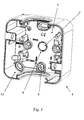
- the figure 7 shows for example that the bottom wall 5 of the mounting box 4 has a rib in the form of a pattern extending over substantially the entire surface of the bottom wall. This rib represents the attachment surface 11. This rib can also be arranged on the gasket 11 itself.
- the invention also relates to a method of placing an electrical appliance 1 as described above, comprising a step of positioning the electrical appliance 1 on a wall, as well as a step of introducing an element through a screw or cable type, through a passage zone 8 into said wall so as to fix the electrical device 1 to said wall.
- this method of implementation comprises a step of cutting at least one seal 11 at a passage area 8, in particular before positioning the electrical apparatus 1, so as to achieve in the joint 11 without removal of material, a discontinuity of passage, such as a simple slot or such that an orifice of dimensions smaller than a through element to pass through said passage zone 8.
- a discontinuity of passage such as a simple slot or such that an orifice of dimensions smaller than a through element to pass through said passage zone 8.
- the cut is made without removal of material, and is therefore simply to achieve in the seal 11, a discontinuity that opens on both sides of said seal 11. Given the elasticity of the seal 11 at the passage zone 8, it is not necessary to remove the material to allow passage of the through element.
- cutting the at least one seal 11 is made by the through element during the introduction step.
- the through element is a screw, which has a cutting edge which can cut the seal 11, or a cable whose section of the metal portion is small enough to pierce the seal 11.
Landscapes
- Engineering & Computer Science (AREA)
- Architecture (AREA)
- Civil Engineering (AREA)
- Structural Engineering (AREA)
- Casings For Electric Apparatus (AREA)
Priority Applications (3)
| Application Number | Priority Date | Filing Date | Title |
|---|---|---|---|
| ES12305211T ES2816627T3 (es) | 2012-02-22 | 2012-02-22 | Aparato eléctrico con estanqueidad reforzada |
| PL12305211T PL2632003T3 (pl) | 2012-02-22 | 2012-02-22 | Urządzenie elektryczne ze wzmocnionym uszczelnieniem |
| EP12305211.0A EP2632003B1 (de) | 2012-02-22 | 2012-02-22 | Elektrogerät mit verstärkter Abdichtung |
Applications Claiming Priority (1)
| Application Number | Priority Date | Filing Date | Title |
|---|---|---|---|
| EP12305211.0A EP2632003B1 (de) | 2012-02-22 | 2012-02-22 | Elektrogerät mit verstärkter Abdichtung |
Publications (2)
| Publication Number | Publication Date |
|---|---|
| EP2632003A1 true EP2632003A1 (de) | 2013-08-28 |
| EP2632003B1 EP2632003B1 (de) | 2020-06-10 |
Family
ID=45999736
Family Applications (1)
| Application Number | Title | Priority Date | Filing Date |
|---|---|---|---|
| EP12305211.0A Active EP2632003B1 (de) | 2012-02-22 | 2012-02-22 | Elektrogerät mit verstärkter Abdichtung |
Country Status (3)
| Country | Link |
|---|---|
| EP (1) | EP2632003B1 (de) |
| ES (1) | ES2816627T3 (de) |
| PL (1) | PL2632003T3 (de) |
Cited By (1)
| Publication number | Priority date | Publication date | Assignee | Title |
|---|---|---|---|---|
| EP3767764A1 (de) * | 2019-07-16 | 2021-01-20 | Niko NV | Montagesystem für elektrische oder elektronische vorrichtungen |
Citations (3)
| Publication number | Priority date | Publication date | Assignee | Title |
|---|---|---|---|---|
| EP1156568A2 (de) * | 2000-05-19 | 2001-11-21 | Ensto Busch-Jaeger Oy | Elektrisches Kabelverbindungsgehäuse und Verfahren zu dessen Herstellung |
| DE102004054174A1 (de) * | 2004-11-10 | 2006-05-11 | Abb Patent Gmbh | Kabeldurchführungsanordnung |
| US20100078189A1 (en) * | 2008-09-30 | 2010-04-01 | Cooper Technologies Company | Environmentally Sealed Wiring Device with Removable Weather-Resistant Cover |
Family Cites Families (1)
| Publication number | Priority date | Publication date | Assignee | Title |
|---|---|---|---|---|
| DE102005045742B4 (de) * | 2005-03-10 | 2008-11-06 | Kaiser Gmbh & Co. Kommanditgesellschaft | Installationsdose für elektrotechnische Zwecke |
-
2012
- 2012-02-22 EP EP12305211.0A patent/EP2632003B1/de active Active
- 2012-02-22 ES ES12305211T patent/ES2816627T3/es active Active
- 2012-02-22 PL PL12305211T patent/PL2632003T3/pl unknown
Patent Citations (3)
| Publication number | Priority date | Publication date | Assignee | Title |
|---|---|---|---|---|
| EP1156568A2 (de) * | 2000-05-19 | 2001-11-21 | Ensto Busch-Jaeger Oy | Elektrisches Kabelverbindungsgehäuse und Verfahren zu dessen Herstellung |
| DE102004054174A1 (de) * | 2004-11-10 | 2006-05-11 | Abb Patent Gmbh | Kabeldurchführungsanordnung |
| US20100078189A1 (en) * | 2008-09-30 | 2010-04-01 | Cooper Technologies Company | Environmentally Sealed Wiring Device with Removable Weather-Resistant Cover |
Cited By (1)
| Publication number | Priority date | Publication date | Assignee | Title |
|---|---|---|---|---|
| EP3767764A1 (de) * | 2019-07-16 | 2021-01-20 | Niko NV | Montagesystem für elektrische oder elektronische vorrichtungen |
Also Published As
| Publication number | Publication date |
|---|---|
| ES2816627T3 (es) | 2021-04-05 |
| PL2632003T3 (pl) | 2020-12-14 |
| EP2632003B1 (de) | 2020-06-10 |
Similar Documents
| Publication | Publication Date | Title |
|---|---|---|
| FR2588332A1 (fr) | Element pour la fixation de pieces a une paroi delimitee par une peau exterieure solide et devant etre remplie de mousse rigide de matiere plastique | |
| EP1595771B1 (de) | Absperrventil für den Wasserkasten eines Kraftfahrzeuges, und solch ein Wasserkasten | |
| EP2632003B1 (de) | Elektrogerät mit verstärkter Abdichtung | |
| EP2940815B1 (de) | Dichter elektrischer schaltschrank zum einbau in eine wand | |
| FR2943017A1 (fr) | Profile pour element de fermeture de benne de vehicule et element de fermeture correspondant | |
| WO2009106771A2 (fr) | Dispositif de montage et de raccordement de conduites d'installations sanitaires prevues en arriere d'une paroi et procede correspondant | |
| EP0647004A1 (de) | Gehäuse für elektrische Einrichtung | |
| FR2974612A1 (fr) | Dispositif de fixation et de raccordement d'un organe d'alimentation d'appareil sanitaire sur une paroi et son procede de montage | |
| EP0736941B1 (de) | Gehäuse für elektrisches Gerät | |
| FR2747851A1 (fr) | Boite de sol, notamment pour appareillage electrique | |
| EP0852205A1 (de) | Verschlusskappe für einen mit einem Befestigungsflansch versehenen Behälter | |
| EP0991155B1 (de) | Gehäuse, insbesondere für elektrische Geräte, dessen Rückwand mit mindestens einem, mit einer Kappe abgedeckten, Loch versehen ist | |
| EP0539293B1 (de) | Runde Leuchte | |
| FR2911727A1 (fr) | Connecteur disposant d'une barriere d'etancheite et procede de fabrication d'un tel connecteur. | |
| FR2705857A1 (fr) | Boîte à couvercle rapporté par encliquetage, notamment pour appareillage électrique. | |
| EP1087486A1 (de) | Adapter zur Befestigung eines electrischen Geräts in vorbestimmter Position | |
| EP1587197B1 (de) | Einbaudose mit Verbindungszubehör für einen Kanal | |
| EP0875974B1 (de) | Unterputzdose in einer Wand geringer Dicke für elektrisches Gerät mit einer Leitungsklappeinführung | |
| FR3039012B1 (fr) | Dispositif d'adaptation d'un boitier d'appareillage electrique a une moulure murale et boitier d'appareillage muni d'un tel dispositif | |
| EP2690734A2 (de) | Dichtungsfuge für Kabeldurchführung | |
| EP1565973B1 (de) | Vorrichtung zum verbinden von flexiblen rohrleitungen | |
| FR2995924A1 (fr) | Auvent d'un nouveau type | |
| EP0971467A1 (de) | Unterputzdose für ein elektrisches Gerät in einer Wand geringer Dicke mit integrierter Spannlasche | |
| FR3055113A1 (fr) | Module de porte a support d’equipement | |
| FR2811817A1 (fr) | Procede de fixation de boites d'encastrement pour composants electriques, telephoniques et similaire dans les parois adossees aux murs exterieurs de maisons ou d'immeubles |
Legal Events
| Date | Code | Title | Description |
|---|---|---|---|
| PUAI | Public reference made under article 153(3) epc to a published international application that has entered the european phase |
Free format text: ORIGINAL CODE: 0009012 |
|
| AK | Designated contracting states |
Kind code of ref document: A1 Designated state(s): AL AT BE BG CH CY CZ DE DK EE ES FI FR GB GR HR HU IE IS IT LI LT LU LV MC MK MT NL NO PL PT RO RS SE SI SK SM TR |
|
| AX | Request for extension of the european patent |
Extension state: BA ME |
|
| 17P | Request for examination filed |
Effective date: 20131107 |
|
| RBV | Designated contracting states (corrected) |
Designated state(s): AL AT BE BG CH CY CZ DE DK EE ES FI FR GB GR HR HU IE IS IT LI LT LU LV MC MK MT NL NO PL PT RO RS SE SI SK SM TR |
|
| STAA | Information on the status of an ep patent application or granted ep patent |
Free format text: STATUS: EXAMINATION IS IN PROGRESS |
|
| 17Q | First examination report despatched |
Effective date: 20170113 |
|
| GRAP | Despatch of communication of intention to grant a patent |
Free format text: ORIGINAL CODE: EPIDOSNIGR1 |
|
| STAA | Information on the status of an ep patent application or granted ep patent |
Free format text: STATUS: GRANT OF PATENT IS INTENDED |
|
| INTG | Intention to grant announced |
Effective date: 20200103 |
|
| GRAS | Grant fee paid |
Free format text: ORIGINAL CODE: EPIDOSNIGR3 |
|
| GRAA | (expected) grant |
Free format text: ORIGINAL CODE: 0009210 |
|
| STAA | Information on the status of an ep patent application or granted ep patent |
Free format text: STATUS: THE PATENT HAS BEEN GRANTED |
|
| AK | Designated contracting states |
Kind code of ref document: B1 Designated state(s): AL AT BE BG CH CY CZ DE DK EE ES FI FR GB GR HR HU IE IS IT LI LT LU LV MC MK MT NL NO PL PT RO RS SE SI SK SM TR |
|
| REG | Reference to a national code |
Ref country code: GB Ref legal event code: FG4D Free format text: NOT ENGLISH |
|
| REG | Reference to a national code |
Ref country code: AT Ref legal event code: REF Ref document number: 1279931 Country of ref document: AT Kind code of ref document: T Effective date: 20200615 Ref country code: CH Ref legal event code: EP |
|
| REG | Reference to a national code |
Ref country code: IE Ref legal event code: FG4D Free format text: LANGUAGE OF EP DOCUMENT: FRENCH |
|
| REG | Reference to a national code |
Ref country code: DE Ref legal event code: R096 Ref document number: 602012070601 Country of ref document: DE |
|
| REG | Reference to a national code |
Ref country code: CH Ref legal event code: NV Representative=s name: DR. GRAF AND PARTNER AG INTELLECTUAL PROPERTY, CH |
|
| REG | Reference to a national code |
Ref country code: LT Ref legal event code: MG4D |
|
| PG25 | Lapsed in a contracting state [announced via postgrant information from national office to epo] |
Ref country code: GR Free format text: LAPSE BECAUSE OF FAILURE TO SUBMIT A TRANSLATION OF THE DESCRIPTION OR TO PAY THE FEE WITHIN THE PRESCRIBED TIME-LIMIT Effective date: 20200911 Ref country code: SE Free format text: LAPSE BECAUSE OF FAILURE TO SUBMIT A TRANSLATION OF THE DESCRIPTION OR TO PAY THE FEE WITHIN THE PRESCRIBED TIME-LIMIT Effective date: 20200610 Ref country code: FI Free format text: LAPSE BECAUSE OF FAILURE TO SUBMIT A TRANSLATION OF THE DESCRIPTION OR TO PAY THE FEE WITHIN THE PRESCRIBED TIME-LIMIT Effective date: 20200610 Ref country code: NO Free format text: LAPSE BECAUSE OF FAILURE TO SUBMIT A TRANSLATION OF THE DESCRIPTION OR TO PAY THE FEE WITHIN THE PRESCRIBED TIME-LIMIT Effective date: 20200910 Ref country code: LT Free format text: LAPSE BECAUSE OF FAILURE TO SUBMIT A TRANSLATION OF THE DESCRIPTION OR TO PAY THE FEE WITHIN THE PRESCRIBED TIME-LIMIT Effective date: 20200610 |
|
| REG | Reference to a national code |
Ref country code: NL Ref legal event code: MP Effective date: 20200610 |
|
| PG25 | Lapsed in a contracting state [announced via postgrant information from national office to epo] |
Ref country code: BG Free format text: LAPSE BECAUSE OF FAILURE TO SUBMIT A TRANSLATION OF THE DESCRIPTION OR TO PAY THE FEE WITHIN THE PRESCRIBED TIME-LIMIT Effective date: 20200910 Ref country code: LV Free format text: LAPSE BECAUSE OF FAILURE TO SUBMIT A TRANSLATION OF THE DESCRIPTION OR TO PAY THE FEE WITHIN THE PRESCRIBED TIME-LIMIT Effective date: 20200610 Ref country code: RS Free format text: LAPSE BECAUSE OF FAILURE TO SUBMIT A TRANSLATION OF THE DESCRIPTION OR TO PAY THE FEE WITHIN THE PRESCRIBED TIME-LIMIT Effective date: 20200610 Ref country code: HR Free format text: LAPSE BECAUSE OF FAILURE TO SUBMIT A TRANSLATION OF THE DESCRIPTION OR TO PAY THE FEE WITHIN THE PRESCRIBED TIME-LIMIT Effective date: 20200610 |
|
| REG | Reference to a national code |
Ref country code: AT Ref legal event code: MK05 Ref document number: 1279931 Country of ref document: AT Kind code of ref document: T Effective date: 20200610 |
|
| PG25 | Lapsed in a contracting state [announced via postgrant information from national office to epo] |
Ref country code: AL Free format text: LAPSE BECAUSE OF FAILURE TO SUBMIT A TRANSLATION OF THE DESCRIPTION OR TO PAY THE FEE WITHIN THE PRESCRIBED TIME-LIMIT Effective date: 20200610 Ref country code: NL Free format text: LAPSE BECAUSE OF FAILURE TO SUBMIT A TRANSLATION OF THE DESCRIPTION OR TO PAY THE FEE WITHIN THE PRESCRIBED TIME-LIMIT Effective date: 20200610 |
|
| PG25 | Lapsed in a contracting state [announced via postgrant information from national office to epo] |
Ref country code: EE Free format text: LAPSE BECAUSE OF FAILURE TO SUBMIT A TRANSLATION OF THE DESCRIPTION OR TO PAY THE FEE WITHIN THE PRESCRIBED TIME-LIMIT Effective date: 20200610 Ref country code: AT Free format text: LAPSE BECAUSE OF FAILURE TO SUBMIT A TRANSLATION OF THE DESCRIPTION OR TO PAY THE FEE WITHIN THE PRESCRIBED TIME-LIMIT Effective date: 20200610 Ref country code: RO Free format text: LAPSE BECAUSE OF FAILURE TO SUBMIT A TRANSLATION OF THE DESCRIPTION OR TO PAY THE FEE WITHIN THE PRESCRIBED TIME-LIMIT Effective date: 20200610 Ref country code: SM Free format text: LAPSE BECAUSE OF FAILURE TO SUBMIT A TRANSLATION OF THE DESCRIPTION OR TO PAY THE FEE WITHIN THE PRESCRIBED TIME-LIMIT Effective date: 20200610 Ref country code: PT Free format text: LAPSE BECAUSE OF FAILURE TO SUBMIT A TRANSLATION OF THE DESCRIPTION OR TO PAY THE FEE WITHIN THE PRESCRIBED TIME-LIMIT Effective date: 20201012 Ref country code: CZ Free format text: LAPSE BECAUSE OF FAILURE TO SUBMIT A TRANSLATION OF THE DESCRIPTION OR TO PAY THE FEE WITHIN THE PRESCRIBED TIME-LIMIT Effective date: 20200610 |
|
| PG25 | Lapsed in a contracting state [announced via postgrant information from national office to epo] |
Ref country code: IS Free format text: LAPSE BECAUSE OF FAILURE TO SUBMIT A TRANSLATION OF THE DESCRIPTION OR TO PAY THE FEE WITHIN THE PRESCRIBED TIME-LIMIT Effective date: 20201010 Ref country code: SK Free format text: LAPSE BECAUSE OF FAILURE TO SUBMIT A TRANSLATION OF THE DESCRIPTION OR TO PAY THE FEE WITHIN THE PRESCRIBED TIME-LIMIT Effective date: 20200610 |
|
| REG | Reference to a national code |
Ref country code: DE Ref legal event code: R097 Ref document number: 602012070601 Country of ref document: DE |
|
| REG | Reference to a national code |
Ref country code: ES Ref legal event code: FG2A Ref document number: 2816627 Country of ref document: ES Kind code of ref document: T3 Effective date: 20210405 |
|
| PLBE | No opposition filed within time limit |
Free format text: ORIGINAL CODE: 0009261 |
|
| STAA | Information on the status of an ep patent application or granted ep patent |
Free format text: STATUS: NO OPPOSITION FILED WITHIN TIME LIMIT |
|
| PG25 | Lapsed in a contracting state [announced via postgrant information from national office to epo] |
Ref country code: DK Free format text: LAPSE BECAUSE OF FAILURE TO SUBMIT A TRANSLATION OF THE DESCRIPTION OR TO PAY THE FEE WITHIN THE PRESCRIBED TIME-LIMIT Effective date: 20200610 |
|
| 26N | No opposition filed |
Effective date: 20210311 |
|
| PG25 | Lapsed in a contracting state [announced via postgrant information from national office to epo] |
Ref country code: SI Free format text: LAPSE BECAUSE OF FAILURE TO SUBMIT A TRANSLATION OF THE DESCRIPTION OR TO PAY THE FEE WITHIN THE PRESCRIBED TIME-LIMIT Effective date: 20200610 |
|
| PG25 | Lapsed in a contracting state [announced via postgrant information from national office to epo] |
Ref country code: MC Free format text: LAPSE BECAUSE OF FAILURE TO SUBMIT A TRANSLATION OF THE DESCRIPTION OR TO PAY THE FEE WITHIN THE PRESCRIBED TIME-LIMIT Effective date: 20200610 |
|
| GBPC | Gb: european patent ceased through non-payment of renewal fee |
Effective date: 20210222 |
|
| PG25 | Lapsed in a contracting state [announced via postgrant information from national office to epo] |
Ref country code: LU Free format text: LAPSE BECAUSE OF NON-PAYMENT OF DUE FEES Effective date: 20210222 |
|
| PG25 | Lapsed in a contracting state [announced via postgrant information from national office to epo] |
Ref country code: IE Free format text: LAPSE BECAUSE OF NON-PAYMENT OF DUE FEES Effective date: 20210222 Ref country code: GB Free format text: LAPSE BECAUSE OF NON-PAYMENT OF DUE FEES Effective date: 20210222 |
|
| PG25 | Lapsed in a contracting state [announced via postgrant information from national office to epo] |
Ref country code: HU Free format text: LAPSE BECAUSE OF FAILURE TO SUBMIT A TRANSLATION OF THE DESCRIPTION OR TO PAY THE FEE WITHIN THE PRESCRIBED TIME-LIMIT; INVALID AB INITIO Effective date: 20120222 Ref country code: CY Free format text: LAPSE BECAUSE OF FAILURE TO SUBMIT A TRANSLATION OF THE DESCRIPTION OR TO PAY THE FEE WITHIN THE PRESCRIBED TIME-LIMIT Effective date: 20200610 |
|
| P01 | Opt-out of the competence of the unified patent court (upc) registered |
Effective date: 20230606 |
|
| PG25 | Lapsed in a contracting state [announced via postgrant information from national office to epo] |
Ref country code: MK Free format text: LAPSE BECAUSE OF FAILURE TO SUBMIT A TRANSLATION OF THE DESCRIPTION OR TO PAY THE FEE WITHIN THE PRESCRIBED TIME-LIMIT Effective date: 20200610 |
|
| PG25 | Lapsed in a contracting state [announced via postgrant information from national office to epo] |
Ref country code: TR Free format text: LAPSE BECAUSE OF FAILURE TO SUBMIT A TRANSLATION OF THE DESCRIPTION OR TO PAY THE FEE WITHIN THE PRESCRIBED TIME-LIMIT Effective date: 20200610 |
|
| PG25 | Lapsed in a contracting state [announced via postgrant information from national office to epo] |
Ref country code: MT Free format text: LAPSE BECAUSE OF FAILURE TO SUBMIT A TRANSLATION OF THE DESCRIPTION OR TO PAY THE FEE WITHIN THE PRESCRIBED TIME-LIMIT Effective date: 20200610 |
|
| PGFP | Annual fee paid to national office [announced via postgrant information from national office to epo] |
Ref country code: DE Payment date: 20250227 Year of fee payment: 14 |
|
| PGFP | Annual fee paid to national office [announced via postgrant information from national office to epo] |
Ref country code: ES Payment date: 20250303 Year of fee payment: 14 |
|
| PGFP | Annual fee paid to national office [announced via postgrant information from national office to epo] |
Ref country code: CH Payment date: 20250306 Year of fee payment: 14 Ref country code: BE Payment date: 20250227 Year of fee payment: 14 |
|
| PGFP | Annual fee paid to national office [announced via postgrant information from national office to epo] |
Ref country code: FR Payment date: 20250225 Year of fee payment: 14 Ref country code: PL Payment date: 20250131 Year of fee payment: 14 |
|
| PGFP | Annual fee paid to national office [announced via postgrant information from national office to epo] |
Ref country code: IT Payment date: 20250220 Year of fee payment: 14 |