EP2631666B1 - High sensitivity single antenna FMCW radar - Google Patents
High sensitivity single antenna FMCW radar Download PDFInfo
- Publication number
- EP2631666B1 EP2631666B1 EP13155116.0A EP13155116A EP2631666B1 EP 2631666 B1 EP2631666 B1 EP 2631666B1 EP 13155116 A EP13155116 A EP 13155116A EP 2631666 B1 EP2631666 B1 EP 2631666B1
- Authority
- EP
- European Patent Office
- Prior art keywords
- signal
- frequency
- fmcw
- path
- transmit
- Prior art date
- Legal status (The legal status is an assumption and is not a legal conclusion. Google has not performed a legal analysis and makes no representation as to the accuracy of the status listed.)
- Active
Links
- 230000035945 sensitivity Effects 0.000 title description 9
- 238000002955 isolation Methods 0.000 claims description 13
- 238000000034 method Methods 0.000 claims description 13
- 238000012545 processing Methods 0.000 claims description 13
- 230000003111 delayed effect Effects 0.000 claims description 3
- 230000001902 propagating effect Effects 0.000 claims description 2
- 230000008569 process Effects 0.000 description 5
- 230000007423 decrease Effects 0.000 description 3
- 238000010586 diagram Methods 0.000 description 3
- 230000005540 biological transmission Effects 0.000 description 2
- 230000015572 biosynthetic process Effects 0.000 description 2
- 238000004891 communication Methods 0.000 description 2
- 230000000694 effects Effects 0.000 description 2
- 230000010354 integration Effects 0.000 description 2
- 230000003595 spectral effect Effects 0.000 description 2
- 238000003786 synthesis reaction Methods 0.000 description 2
- 230000008901 benefit Effects 0.000 description 1
- 238000006243 chemical reaction Methods 0.000 description 1
- 230000001427 coherent effect Effects 0.000 description 1
- 230000008878 coupling Effects 0.000 description 1
- 238000010168 coupling process Methods 0.000 description 1
- 238000005859 coupling reaction Methods 0.000 description 1
- 230000003247 decreasing effect Effects 0.000 description 1
- 238000013461 design Methods 0.000 description 1
- 238000001514 detection method Methods 0.000 description 1
- 230000009977 dual effect Effects 0.000 description 1
- 230000007613 environmental effect Effects 0.000 description 1
- 238000009499 grossing Methods 0.000 description 1
- 230000001771 impaired effect Effects 0.000 description 1
- 238000009434 installation Methods 0.000 description 1
- 238000005259 measurement Methods 0.000 description 1
- 238000001556 precipitation Methods 0.000 description 1
- 230000000644 propagated effect Effects 0.000 description 1
- 230000009467 reduction Effects 0.000 description 1
- 230000004044 response Effects 0.000 description 1
- 238000001228 spectrum Methods 0.000 description 1
- 230000007480 spreading Effects 0.000 description 1
- 238000012360 testing method Methods 0.000 description 1
Images


Classifications
-
- G—PHYSICS
- G01—MEASURING; TESTING
- G01S—RADIO DIRECTION-FINDING; RADIO NAVIGATION; DETERMINING DISTANCE OR VELOCITY BY USE OF RADIO WAVES; LOCATING OR PRESENCE-DETECTING BY USE OF THE REFLECTION OR RERADIATION OF RADIO WAVES; ANALOGOUS ARRANGEMENTS USING OTHER WAVES
- G01S13/00—Systems using the reflection or reradiation of radio waves, e.g. radar systems; Analogous systems using reflection or reradiation of waves whose nature or wavelength is irrelevant or unspecified
- G01S13/88—Radar or analogous systems specially adapted for specific applications
- G01S13/882—Radar or analogous systems specially adapted for specific applications for altimeters
-
- G—PHYSICS
- G01—MEASURING; TESTING
- G01S—RADIO DIRECTION-FINDING; RADIO NAVIGATION; DETERMINING DISTANCE OR VELOCITY BY USE OF RADIO WAVES; LOCATING OR PRESENCE-DETECTING BY USE OF THE REFLECTION OR RERADIATION OF RADIO WAVES; ANALOGOUS ARRANGEMENTS USING OTHER WAVES
- G01S13/00—Systems using the reflection or reradiation of radio waves, e.g. radar systems; Analogous systems using reflection or reradiation of waves whose nature or wavelength is irrelevant or unspecified
- G01S13/02—Systems using reflection of radio waves, e.g. primary radar systems; Analogous systems
- G01S13/06—Systems determining position data of a target
- G01S13/08—Systems for measuring distance only
- G01S13/32—Systems for measuring distance only using transmission of continuous waves, whether amplitude-, frequency-, or phase-modulated, or unmodulated
- G01S13/34—Systems for measuring distance only using transmission of continuous waves, whether amplitude-, frequency-, or phase-modulated, or unmodulated using transmission of continuous, frequency-modulated waves while heterodyning the received signal, or a signal derived therefrom, with a locally-generated signal related to the contemporaneously transmitted signal
- G01S13/343—Systems for measuring distance only using transmission of continuous waves, whether amplitude-, frequency-, or phase-modulated, or unmodulated using transmission of continuous, frequency-modulated waves while heterodyning the received signal, or a signal derived therefrom, with a locally-generated signal related to the contemporaneously transmitted signal using sawtooth modulation
-
- G—PHYSICS
- G01—MEASURING; TESTING
- G01S—RADIO DIRECTION-FINDING; RADIO NAVIGATION; DETERMINING DISTANCE OR VELOCITY BY USE OF RADIO WAVES; LOCATING OR PRESENCE-DETECTING BY USE OF THE REFLECTION OR RERADIATION OF RADIO WAVES; ANALOGOUS ARRANGEMENTS USING OTHER WAVES
- G01S7/00—Details of systems according to groups G01S13/00, G01S15/00, G01S17/00
- G01S7/02—Details of systems according to groups G01S13/00, G01S15/00, G01S17/00 of systems according to group G01S13/00
- G01S7/03—Details of HF subsystems specially adapted therefor, e.g. common to transmitter and receiver
- G01S7/038—Feedthrough nulling circuits
-
- G—PHYSICS
- G01—MEASURING; TESTING
- G01S—RADIO DIRECTION-FINDING; RADIO NAVIGATION; DETERMINING DISTANCE OR VELOCITY BY USE OF RADIO WAVES; LOCATING OR PRESENCE-DETECTING BY USE OF THE REFLECTION OR RERADIATION OF RADIO WAVES; ANALOGOUS ARRANGEMENTS USING OTHER WAVES
- G01S7/00—Details of systems according to groups G01S13/00, G01S15/00, G01S17/00
- G01S7/02—Details of systems according to groups G01S13/00, G01S15/00, G01S17/00 of systems according to group G01S13/00
- G01S7/35—Details of non-pulse systems
- G01S7/352—Receivers
- G01S7/354—Extracting wanted echo-signals
-
- H—ELECTRICITY
- H03—ELECTRONIC CIRCUITRY
- H03L—AUTOMATIC CONTROL, STARTING, SYNCHRONISATION, OR STABILISATION OF GENERATORS OF ELECTRONIC OSCILLATIONS OR PULSES
- H03L7/00—Automatic control of frequency or phase; Synchronisation
- H03L7/06—Automatic control of frequency or phase; Synchronisation using a reference signal applied to a frequency- or phase-locked loop
- H03L7/16—Indirect frequency synthesis, i.e. generating a desired one of a number of predetermined frequencies using a frequency- or phase-locked loop
- H03L7/18—Indirect frequency synthesis, i.e. generating a desired one of a number of predetermined frequencies using a frequency- or phase-locked loop using a frequency divider or counter in the loop
- H03L7/197—Indirect frequency synthesis, i.e. generating a desired one of a number of predetermined frequencies using a frequency- or phase-locked loop using a frequency divider or counter in the loop a time difference being used for locking the loop, the counter counting between numbers which are variable in time or the frequency divider dividing by a factor variable in time, e.g. for obtaining fractional frequency division
- H03L7/1974—Indirect frequency synthesis, i.e. generating a desired one of a number of predetermined frequencies using a frequency- or phase-locked loop using a frequency divider or counter in the loop a time difference being used for locking the loop, the counter counting between numbers which are variable in time or the frequency divider dividing by a factor variable in time, e.g. for obtaining fractional frequency division for fractional frequency division
-
- G—PHYSICS
- G01—MEASURING; TESTING
- G01S—RADIO DIRECTION-FINDING; RADIO NAVIGATION; DETERMINING DISTANCE OR VELOCITY BY USE OF RADIO WAVES; LOCATING OR PRESENCE-DETECTING BY USE OF THE REFLECTION OR RERADIATION OF RADIO WAVES; ANALOGOUS ARRANGEMENTS USING OTHER WAVES
- G01S7/00—Details of systems according to groups G01S13/00, G01S15/00, G01S17/00
- G01S7/02—Details of systems according to groups G01S13/00, G01S15/00, G01S17/00 of systems according to group G01S13/00
- G01S7/027—Constructional details of housings, e.g. form, type, material or ruggedness
Definitions
- a frequency modulated continuous wave (FMCW) radar can be designed to transmit and receive from the same antenna, or to transmit and receive from separate antennas. Using separate antennas for transmitting and receiving provides improved isolation between the transmit and receive path at the expense of increased size to accommodate each of the antennas and provide spacing between the antennas.
- radars can be designed to transmit and receive from a single antenna. Using a single antenna, however, decreases the isolation between the transmit and receive path resulting in increased coupling of signals from the transmit path into the receive path. These signals from the transmit path appear as noise in the receive path and reduce the sensitivity of the receiver. If enough signal from the transmit path is coupled into the receive path, the transmit signal can drown out the receive signal entirely. In high precision radar applications, such as in radar altimeters for aircraft, radar sensitivity can be crucial.
- the frequency range in which a radar operates also has an effect on the performance of the radar.
- the frequency range used by a radar can be based on available spectrum as well as the distance that the radar will be measuring. For example, aircraft radar altimeters can be required to measure a wide range of distance, from 15,000ft down to 5ft. Also, commercial radar altimeters are currently required to operate between 4.2-4.4GHz.
- US patent 4968967 discloses a continuously transmitting and receiving radar comprises a transmitter, a receiver, an antenna and a circulator for effecting communication between the transmitter and the antenna and between the antenna and the receiver.
- a reflected power canceller is provided for suppressing the effects of leakage between the transmitter and receiver.
- the reflected power canceller comprises a directional coupler for supplying a part of the transmitted signal to a modulator which forms a cancelling signal by adjusting the phase and amplitude of the sampled signal.
- the cancelling signal is applied to another directional coupler which subtracts the cancelling signal from the leakage and wanted signals.
- a narrowband control path is connected between the output of the receiver and the modulator.
- a time delay device is provided in the signal path from the coupler to the modulator. The time delay introduced by the device is set so that the propagation times between the transmitter and the directional coupler via the circulator and via the modulator are the same.
- US patent application, publication number US2011122017A1 discloses a high resolution, low power marine FM/CW radar for use in applications such as the newly mandated barge/river radars that are to be used in very confined spaces such as canals.
- an FMCW radar and corresponding method of transmitting a FMCW signal as claimed in the accompanying claims.
- FIG 1 is a block diagram of an example FMCW radar 100.
- the FMCW radar 100 can transmit and receive from a single antenna 102 with high sensitivity.
- a circulator 108 couples a transmit path 104 and a receive path 106 to the antenna 102 and provides some isolation of the receive path 106 from the transmit path 104.
- the circulator 108 is a conventional circulator commercially available and provides at least 20 dB of isolation from the output of the coupler 116 (from the transmit path 104) to the input of the receiver mixer 118 (toward the receive path 106).
- the circulator 108 provides isolation for signals from the transmit path 104 leaking directly into the receive path 106, the circulator 108 does not protect against signals from the transmit path 104 that are reflected off of the single antenna 102.
- This reflected signal 110 is received at the port of the circulator 108 that is coupled to the antenna 102.
- the signal received by the antenna also referred to herein as "the received signal” is also received at this port of the circulator 108.
- the circulator 108 allows both the reflected signal 110 and the received signal to pass through to the receive path 106.
- the phase noise from this reflected signal 110 can increase the noise in the receive path 106. Accordingly, this reflected signal 110 is a concern for the FMCW radar 100 because large amplitude reflections 110 can cause the continuously transmitting FMCW signal to jam the receiver, thereby limiting sensitivity.
- the antenna 102 has a low reflection level from the transmit path 104 (at least 20dB below the incident level), a transmitter power level (e.g., amplifier 124) that is less than 23 dBm, and low phase noise from the transmitter (better than -120dBc/Hz at 100 KHz offset).
- the magnitude of the reflection from the antenna 102 is less than or equal to the isolation level of the circulator 108.
- the magnitude of the reflection from the antenna 102 is known by two terms voltage standing wave ratio (VSWR) and return loss. If the circulator 108 has 20 dB of isolation, than the return loss should be 20 dB or greater. Thus, the reflected power level will be at least 20 dB below the incident power level. In an example, the VSWR of the antenna 102 is less than 1.2 to 1.
- the transmitter power level that is, the power level of the amplifier 124, is controlled such that the power level of the FMCW signal in the transmit path 104 is less than 23 dBm. Signals in the transmit path 104 having too high of power may cause too much power to reach the mixer 118 in the receive path 106 due to the limited isolation of the circulator 108 and the reflection level from a realizable antenna 102 (return loss of greater than 20dB, VSWR ⁇ 1.2:1).
- the FMCW radar 100 also addresses the phase noise of the transmitter as discussed in more detail below.
- Phase noise in the received signal can also be obtained from a leakage signal 115 due to the limited isolation of the circulator 108 between the transmit path 104 and the receive path 106.
- the leakage signal 115 leaks through the circulator 108 from the transmit path 104 into the receive path 106. Because the leakage signal 115 may be of the same order of magnitude as the reflected signal 110, the phase noise of the transmitter contributed by the leakage path would also cause severe reduction in sensitivity of the receiver.
- the noise from the reflected signal 110 and the leakage signal 115 in the FMCW radar 100 can also be limited by using a delay match path 112.
- the delay match path 112 uses a reference signal (also referred to herein as the "local oscillator reference signal 114") to cancel transmitter phase noise from the reflected signal 100 and the leakage signal 115 that would otherwise be converted into noise in the receive path 106 and reduce sensitivity.
- the local oscillator reference signal 114 is a portion of the signal from the transmit path 104 that is coupled into the delay match path 112 by a coupler 116. This local oscillator reference signal 114 is provided to a mixer 118 along with the signals arriving from the antenna 102.
- the mixer 118 effectively subtracts the local oscillator reference signal 114 from the signals arriving form the antenna 102.
- the propagation time (T120) of the local oscillator reference signal 114 from the coupler 116 to the mixer 118 through the delay path 112 is set based on the propagation time (T110) of the reflected signal 110 from the coupler 116 off of the antenna 102 and to the mixer 118.
- the propagation time (T110) of the reflected signal 110 is based on the distance from the coupler 116 to the antenna 102 and from the antenna 102 to the mixer 118.
- the propagation time (T110) is based on the physical length of the path of the electrical signal through the corresponding elements and connecting transmission lines of the FMCW radar 100.
- the propagation time (T110) of the reflected signal 110 is also based on the propagation speed of the signals as they are reflected from the antenna 102.
- the antenna 102 is selected to have desirable group delay characteristics.
- Group delay refers to the propagation speed of signals at different frequencies as those signals reflect off of the antenna 102.
- many antennas have different propagation speeds for signals of different frequencies. In such antennas having differing propagation speeds, it may be more difficult to cancel out the reflected signal 110, since different frequencies within the reflected signal 110 are in different alignment from where they were in the transmit path 104.
- many of the antennas have a non-linear relationship between propagation speed and frequency, adding to the difficulty of cancellation.
- the antenna 102 is selected to have a sufficiently flat group delay over the frequencies in the reflected signals 110, typically on the order of +/- 1nSec. In an example, the antenna has a substantially flat group delay over the entire swept bandwidth of the transmitted FMCW signal.
- the propagation time (T120) of the delay match path 114 is set to be between the propagation time (T110) of the reflected signal 110 and the propagation time of the leakage signal 115.
- the propagation time (T120) of the delay match path 114 can be set closer to the propagation time of the signal (reflected or leakage) that is stronger in the receive path 106. The stronger one of the signals (reflected or leakage) is relative to the other can determine how close the propagation time (T120) of the delay match path 114 is set to the propagation time of that signal.
- the delay match path 112 includes a delay element 120 to provide a set delay to the local oscillator reference signal 114.
- the mixer 118 is configured to combine the local oscillator reference signal 114 with the signal from the circulator 108 (which includes the reflected signal 110).
- the delay element 120 comprises a propagation path having a length that is substantially equal to the set delay in seconds multiplied by the propagation speed of the local oscillator reference signal 114. Accordingly, the set delay can be configured by adjusting the length of the propagation path of the delay path 112.
- the delay element 120 can be configured such that the distance of the delay match path 112 is within 0.05 meters of the distance from the coupler 116 to the antenna 102 and then to the mixer 116. As the difference in length between the two paths decreases the phase noise cancellation increases.
- the coupler 116 is a hybrid coupler such that a signal reflected from the circulator 108 is terminated in a load.
- the physical length of the electrical path for the leakage signal 115 is shorter than for the reflected signal 110.
- the electrical length of the reflected signal 110 is kept short (e.g., as short as possible) in order to reduce the difference between the length of the leakage signal 115 and the length of the reflective signal 110.
- the antenna 102 is connected closely (e.g., as closely as physically possible) to the circulator 108. In particular, the antenna 102 cannot be remotely located from the circulator 108 or the overall benefit of the system (increased sensitivity) will be impaired.
- the antenna 102 is composed of one or more resonant elements and is within 1 to 2 cm of the circulator 108. The closer the antenna 102 is to the coupler 116, the less delay that is needed by the delay element 120.
- the transmit path 104 of the FMCW radar 100 generates a FMCW linear ramp signal to be propagated from the radar 100.
- the FMCW linear signal can ramp (e.g., an increasing ramp) in frequency over time from a starting frequency to an ending frequency. Upon reaching the ending frequency, the FMCW linear signal can return to the starting frequency in order to repeat the ramp.
- the return to the starting frequency can be a ramp (e.g., a decreasing ramp) at the same rate as the ramp from the starting frequency to the ending frequency. In other examples, however, the return to the starting frequency can be immediate (e.g., no ramp).
- the FMCW linear signal can include a repeating linear ramp from a starting frequency to an ending frequency.
- this repeating FMCW linear ramp signal can be used in a radar for determining a distance to an object off of which the FMCW linear ramp signal reflects.
- the FMCW signal is generated using a voltage controller oscillator (VCO) 122 and a transmit amplifier 124.
- VCO voltage controller oscillator
- PLL phase-locked loop
- the PLL includes a fractional-n synthesizer 126 to control the VCO 122.
- the fractional-n synthesizer comprises an integrated circuit (IC) chip that meets or exceeds all performance minimums listed herein. Additionally, some performance minimums are required of other components of the PLL as indicated herein.
- the performance minimums include that the fractional-n synthesizer 126 have a phase detector frequency of at least 100MHz. Accordingly, during operation the phase detector frequency of the fractional-n synthesizer 126 is set to 100MHz or greater.
- the phase detector frequency of the synthesizer is set to 160MHz.
- the performance minimums also include that the master clock 131 has a phase noise equal to or better than -150 dBc/Hz at 100kHz offset.
- the PLL should use the lowest possible ratio for frequency division up to a phase detector frequency of 160 MHz.
- the performance minimums include that a frequency step size applied by the fractional-n synthesizer 126 is sufficiently small, on the order to 100 Khz, to not cause spectral sidebands in the Fourier Transform used to derive the altitude range bins.
- the PLL loop filter then provides smoothing of these frequency steps.
- the loop bandwidth of the PLL is on the order of less than 100 KHz, which is less than the frequency step size.
- the performance minimums include that the fractional-n synthesizer 126 provide means to synthesize the desired frequency sweep bandwidth of the transmit signal in response to commands issued by a processing device 132,(e.g., an FPGA/PLD).
- the fractional-n-synthesizer 126 is commanded by the processing device 132 to set the starting frequency, ending frequency, and step-size required to achieve the desired frequency sweep bandwidth in the desired modulation period and maintain the FMCW linear ramp signal within the desired range.
- An example fractional-n synthesizer 126 that meets the performance minimums is the dual mode fractional-n/integer-n synthesizer ADF4159 from Analog Devices.
- the PLL can also include a separate amplifier 128 and a loop filter 130 to generate the tuning control signal for the VCO 122 from the output of the fractional-n synthesizer 126.
- the amplifier 128 and loop filter 130 are not used if the charge pump of the fractional-n synthesizer 126 can drive the VCO 122 directly and include loop filter components in conjunction with the charge pump output.
- the fractional-n synthesizer 126 implements a FMCW linear signal (waveform) by scheduling a small fixed frequency step to be added to or subtracted from the starting frequency until the ending frequency is reached.
- the fractional-n synthesizer 126 does not use a phase accumulator as in direct digital synthesis (DDS) architectures.
- the ramp for the signal is implemented by performing linear steps.
- the output of the transmit amplifier 124 is a linear frequency sweep of 200 MHz modulated bandwidth between 4200-4400 MHz.
- the output of the VCO 122 can be tuned at least 300 MHz centered about 4300 MHz.
- the receive path 106 of the radar 100 includes the mixer 118 as previously mentioned.
- the receive path 106 also includes an amplifier 134, high pass filter 136, another amplifier 138, low pass filter 140, and an analog to digital converter 142 to process the received signal.
- a matching network is used to reduce the reflected power from the antenna 102 to go back towards the circulator 108 and be passed to the mixer 118.
- the received signal is provided to a processing device such as a digital signal processor (DSP).
- DSP digital signal processor
- the frequency difference generated by the mixer 118 is provided to the HPF 136, which filters the received analog signal according to a 6 dB per octave slope of gain versus frequency before the received signal is passed to the band limiting low pass filter 140.
- the 6 dB per octave slope is used in examples when radar 100 is configured as a radar altimeter.
- the radar 100 is configured as a target detection radar and uses a slope of 12 dB per octave.
- the radar 100 is configured as a weather or precipitation radar and uses a 9 dB per octave slope.
- This high pass filter compensates directly for the propagation losses over the distance transmitted and reflective signal travel. After the filter, a signal reflected from a fixed size target appears to have the same amplitude at all ranges. Then the received signal is sent to the A/D 142. The digital output of the A/D 142 is sent to a DSP which processes the digital output as described below.
- the clock signal for the A/D 142 is derived from the master clock 131.
- the clock signal for the A/D 142 is of low phase noise with resulting low jitter to ensure that the signal to noise ratio at the input to the A/D 142 is not degraded by phase noise of the clock signal.
- the clock signal is also coherent with the radar synthesis system.
- the clock signal for the A/D 142 cannot be generated by any other independent means such as by a DSP clock system or a clock system of the processing device 132(e.g., an FPGA/PLD).
- the processing device 132 may be used to divide the frequency of the master clock 131 to the value used to drive the A/D 142, but the processing device 132 must not use an external FPGA clock in any way to accomplish the frequency division.
- FIG. 2 is an example radar altimeter system 30 including the FMCW radar 100.
- the system 30 can provide accurate radar altimeter measurements and tail strike warnings.
- the system 30 includes a signal processing system 32.
- the signal processing system 32 includes a processor 36, an altitude computation processor (ACP) 37 and an input/output device 38.
- the processor 36 is a digital signal processor (DSP) or a field programmable gate array (FPGA) that is configured to perform Fast Fourier Transform (FFT).
- DSP digital signal processor
- FPGA field programmable gate array
- the FMCW radar 100 is in signal communication with the signal processing system 32 and other aircraft systems, such as a ground-proximity warning system.
- the FMCW radar 100 sends data received from the A/D 142 to the processor 36, which in turn transforms the data to altitude bin data and provides it to the ACP 37.
- the ACP 37 analyzes the altitude bin data to determine distance to ground values.
- the ACP 37 can generate a tail strike warnings based on the distance to ground values. If the ACP 37 produces a tail strike warning, the input/output device 38 presents a warning to the flight crew.
- the transmitter 56 shown in Figure 2 includes components of the transmit path 104 such as the VCO 122, transmit amplifier 124, coupler 125, and the fractional-n synthesizer 126.
- the receiver 58 of Figure 2 includes components of the receive path such as the amplifier 134, high pass filter 136, amplifier 138, and low pass filter 140.
- the FMCW radar 100 also includes a delay match path with a delay element 120 to cancel out most or all phase noise contained within a reflected signal 110 and the leakage signal 115 in the receiver mixer 118 before the desired delayed target reflection signals are processed by the receiver 58.
- the DSP 36 can send a control signal to the processing device 132 which converts the control signal from the DSP 36 into commands for the fractional-n synthesizer 126 that translate into a linear frequency modulation of a particular bandwidth and period for the FMCW signal.
- the DSP 36 can also send control signals for calibration or self-test of the radar 100.
- the DSP 36 receives the digital output of sampled data from the A/D 142.
- the DSP 36 computes Fast Fourier Transforms (FFT) of the sampled data.
- the resulting frequency bins of the FFT correspond to incremental altitude bins.
- the ACP 37 uses algorithms to evaluate the altitude frequency bins to determine the aircraft height above the ground. Those algorithms may also determine if the potential exists for a tail strike during take off and report that information via the Input/Output Device 38 to other aircraft systems such as the flight controls.
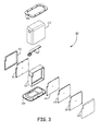
- Figures 3 and 4 illustrate an example physical implementation of the radar altimeter system 30.
- Figure 3 is an exploded view of the radar altimeter system 30.
- the system 30 includes an outer housing 302 that can protect the electronics from the external environment.
- the outer housing 302 mounts to an antenna cover 304 which includes the antenna 102.
- the antenna cover 304 can be configured to mount to the outside of the aircraft skin.
- An input/output interconnect 308 is configured to fit primarily within the outer housing 302 and extend through an aperture in the outer housing 302 to enable interconnect with external systems.
- the connector 308 contains only power supply, and digital and analog signals used to control and monitor performance of the altimeter.
- An RF circuit board 310 includes the analog and digital RF components of the transmitter and receiver.
- the RF circuit board 310 is coupled to the antenna 102 via a blind mate connector for transmission and reception of signals.
- a first cover 312 provides isolation for the analog and digital (e.g., the fractional-N-synthesizer) RF components on the RF circuit board 310.
- the RF circuit board 310 is mounted to a first side of a structural backbone 314 which is mounted to the antenna cover 304 and provides support and further isolation for the RF circuit board 310.
- the RF circuit board 310 includes components such as the fractional-n synthesizer 126, the transmit amplifier 124, the processing device 132, the master clock 131, and the A/D 142.
- the digital circuit board 316 includes digital components such as the DSP, Memory and Input/Output Devices.
- the digital circuit board 316 is isolated by the structural backbone 314 and a second cover 318.
- On the opposite side of the second cover 318 from the digital circuit board 316 is a power supply board 320.
- the power supply board 320 is isolated by the second cover 318 and a third cover 322.
- Each of the third cover 322, power supply board 320, second cover 318, and digital circuit board 316 are a planar structure.
- planar structures are disposed parallel and adjacent to one another and mounted to a second side of the structural backbone 314 such that the sides of each planar structure are facing the sides of the neighboring planar structure.
- the RF circuit board 310 and the first cover 312 are also planar structures that are disposed parallel and adjacent to one another and mounted to the first side of the structure backbone 314 such that a side of the first cover 312 is facing a side of the RF circuit board 310.
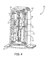
- FIG 4 is a cut-away view of the radar altimeter system 30.
- the outer housing 302 is mounted to the antenna cover 304 which together enclose the electronic components.
- the structural backbone 314 is mounted to the antenna cover 304 and to a portion of the outer housing 302.
- the first cover 312 and RF circuit board 310 are mounted to a first side of the structural backbone 314.
- the third cover 322, power supply circuit board 320, second cover 318, and digital circuit board 316 are mounted to a second and opposite side of the structural backbone 314.
- the assembled radar altimeter system 30 is configured to mount to another member via the antenna cover 304 attaching to the other member.
- the physical design described with respect to Figures 3 and 4 is important to achieving the desired performance because it enables a short connection distance between the circulator 108 and the antenna 102. While it may be possible to implement a printed antenna on one side of a printed circuit board and the transmitter and receiver circuitry on the back side of a circuit board to provide intimate integration and minimal distance between the circulator and the antenna, this configuration does not allow the unit to be easily packaged for pressure differential (outside to inside an aircraft which can be 30,000 ft. or more) and moisture protection.
- the shape of the package enables the radar altimeter system 30 to fit within a re-enforcement structure (stringers and frames) of the fuselage.
- newer class aircraft use stringers that are narrowly spaced.
- the package of the altimeter is designed to avoid cutting away any stringer or frames to allow installation. This reduces the cost of integration of the radar altimeter system 30 and achieves a large weight saving by eliminating the need to add "sister" structure stringers and frames that would otherwise have been cut away to make room for the altimeter environmental cover and connector.
- the aspect ratio and the height of the package have been set such that the radar altimeter system 30 will fit on a large number of aircraft fuselages with little impact to the fuselage structure.
- Example 1 includes a frequency modulated continuous wave (FMCW) radar comprising: a single antenna; a transmit path coupled to the single antenna and configured to provide a FMCW signal thereto, the transmit path including a voltage controlled oscillator controlled by a phase-locked loop, the phase-locked loop including a fractional-n synthesizer integrated circuit (IC) configured to implement a FMCW ramp waveform that ramps from a starting frequency to an ending frequency and upon reaching the ending frequency returns to the starting frequency to ramp again; a receive path coupled to the single antenna and configured to include a reflected version of the FMCW signal as a reflected signal and a portion of the FMCW signal leaking through a circulator as a leakage signal, the receive path including components configured to filter and sample a signal in the receive path; and a delay path coupled between a coupler on the transmit path and a mixer in the receive path, the delay path including a delay element configured to delay a local oscillator reference signal from the transmit path such that the propagation time of the local oscillator reference signal from
- Example 2 includes the FMCW radar of Example 1, wherein the antenna has a substantially flat group delay over the entire swept bandwidth of the FMCW signal.
- Example 3 includes the FMCW radar of any of Examples 1 or 2, wherein the circulator provides at least 20 dB of isolation from signals in the transmit path to the receive path.
- Example 4 includes the FMCW radar of any of Examples 1-3, wherein the antenna has a voltage standing wave ratio of less than 1.2 to 1 and a return loss of greater than 20 dB.
- Example 5 includes the FMCW radar of any of Examples 1-4, wherein the transmit path also includes an amplifier coupled to the output of the voltage controlled oscillator to amplify a transmitted signal in the transmit path, wherein the amplifier is controlled such that the transmitted signal is less than 23 dBm.
- Example 6 includes the FMCW radar of any of Examples 1-5, wherein the fractional-n-synthesizer IC has a phase detector frequency of at least 100 MHz.
- Example 7 includes the FMCW radar of Example 6, wherein a phase detector frequency of the fractional-n-synthesizer IC is set to 160 MHz.
- Example 8 includes the FMCW radar of any of Examples 1-7, comprising a master clock coupled to the fractional-n-synthesizer to provide a clock signal for the fractional-n-synthesizer, wherein the master clock has a phase noise equal to or better than -150 dBc/Hz at 100 kHz offset.
- Example 9 includes the FMCW radar of any of Examples 1-8, wherein a return from the ending frequency to the starting frequency is also a ramp.
- Example 10 includes the FMCW radar of any of Examples 1-9, wherein the ramp from the starting frequency to the ending frequency is linear.
- Example 11 includes the FMCW radar of Example 10, wherein the fractional-n-synthesizer is configured to implement the FMCW linear ramp signal by scheduling frequency steps to be added to or subtracted from the starting frequency until the ending frequency is reached.
- Example 12 includes the FMCW radar of any of Examples 1-11, wherein a processing device is coupled to the fractional-n-synthesizer and configured to control operation of the fractional-n-synthesizer, wherein the fractional-n-synthesizer is configured to synthesize a frequency sweep bandwidth or a frequency deviation of the FMCW linear ramp signal based on a commanded frequency deviation or frequency sweep bandwidth to maintain the FMCW linear ramp signal within the desired range.
- a processing device is coupled to the fractional-n-synthesizer and configured to control operation of the fractional-n-synthesizer, wherein the fractional-n-synthesizer is configured to synthesize a frequency sweep bandwidth or a frequency deviation of the FMCW linear ramp signal based on a commanded frequency deviation or frequency sweep bandwidth to maintain the FMCW linear ramp signal within the desired range.
- Example 13 includes a method of transmitting a frequency modulated continuous wave (FMCW) signal, the method comprising: providing a plurality of fixed frequency steps to a voltage controlled oscillator using a fractional-n-synthesizer, wherein the plurality of fixed frequency steps are configured to implement a linear ramp in frequency from a starting frequency to an ending frequency and upon reaching the ending frequency returning to the starting frequency; amplifying an output of the voltage controlled oscillator such to create a transmit signal, wherein amplifying the output includes amplifying the output by less than 23 dBm; propagating the transmit signal from an antenna; sensing reflections of the transmit signal; sensing signals at the antenna, wherein a receive path signal includes signals sensed by the antenna, reflections of the transmit signal off of the antenna, and leakage of the transmit signal through a circulator; subtracting a portion of the transmit signal, referred to as a local oscillator reference signal, with the receive path signal to cancel out phase noise in the receive path signal from the reflections and leakage of the transmit signal
- Example 14 includes the method of Example 13, comprising: delaying the portion of the transmit signal that is subtracted from the receive path signal with the receive path signal for a set delay, such that the propagation time of the local oscillator reference signal from is between the propagation time of the reflection of the transmit signal and the leakage of the transmit signal.
- Example 15 includes the method of Example 14, comprising: providing a clock signal to the fractional-n-synthesizer having phase noise equal to or better than - 150 dBc/Hz at 100 kHz offset.
- Example 16 includes a frequency modulated continuous wave (FMCW) radar altimeter system comprising: a single antenna; a transmit path coupled to the single antenna and configured to provide a FMCW signal thereto, the transmit path including a voltage controlled oscillator controlled by a phase-locked loop, the phase-locked loop including a fractional-n synthesizer integrated circuit (IC) configured to implement a FMCW ramp waveform that ramps from a starting frequency to an ending frequency and upon reaching the ending frequency returns to the starting frequency to ramp again; a receive path coupled to the single antenna and configured to receive a reflected version of the FMCW signal, the receive path including components configured to filter and sample a signal in the receive path; a delay path coupled between a coupler on the transmit path and a mixer in the receive path, the delay path including a delay element configured to delay a local oscillator reference signal from the transmit path such that the propagation time of the local oscillator reference signal from the coupler to the mixer through the delay path is the same as the propagation time of a reflected signal from
- Example 17 includes the FMCW radar altimeter system of Example 16, wherein the antenna has a substantially flat group delay across the entire modulation bandwidth and a voltage standing wave ratio of less than 1.2 to 1 and a return loss of greater than 20 dB.
- Example 18 includes the FMCW radar altimeter system of any of Examples 16 or 17, wherein the transmit path also includes an amplifier coupled to the output of the voltage controlled oscillator to amplify a transmitted signal in the transmit path, wherein the amplifier is controlled such that the transmitted signal is less than 23 dBm.
- Example 19 includes the FMCW radar altimeter system of any of Examples 16-18, comprising a master clock coupled to the fractional-n-synthesizer to provide a clock signal for the fractional-n-synthesizer, wherein the master clock has a phase noise equal to or better than -150 dBc/Hz at 100 kHz offset, and wherein the fractional-n-synthesizer IC has a phase detector frequency of at least 100 MHz.
- Example 20 includes the FMCW radar altimeter system of Examples 16-19, wherein a return from the ending frequency to the starting frequency is also a ramp, and wherein the ramp from the starting frequency to the ending frequency is linear; wherein the fractional-n-synthesizer is configured to implement the FMCW linear ramp signal by scheduling fixed frequency steps to be added to or subtracted from the starting frequency until the ending frequency is reached.
Description
- A frequency modulated continuous wave (FMCW) radar can be designed to transmit and receive from the same antenna, or to transmit and receive from separate antennas. Using separate antennas for transmitting and receiving provides improved isolation between the transmit and receive path at the expense of increased size to accommodate each of the antennas and provide spacing between the antennas. In order to reduce the size, radars can be designed to transmit and receive from a single antenna. Using a single antenna, however, decreases the isolation between the transmit and receive path resulting in increased coupling of signals from the transmit path into the receive path. These signals from the transmit path appear as noise in the receive path and reduce the sensitivity of the receiver. If enough signal from the transmit path is coupled into the receive path, the transmit signal can drown out the receive signal entirely. In high precision radar applications, such as in radar altimeters for aircraft, radar sensitivity can be crucial.
- The frequency range in which a radar operates also has an effect on the performance of the radar. The frequency range used by a radar can be based on available spectrum as well as the distance that the radar will be measuring. For example, aircraft radar altimeters can be required to measure a wide range of distance, from 15,000ft down to 5ft. Also, commercial radar altimeters are currently required to operate between 4.2-4.4GHz.
-
US patent 4968967 discloses a continuously transmitting and receiving radar comprises a transmitter, a receiver, an antenna and a circulator for effecting communication between the transmitter and the antenna and between the antenna and the receiver. A reflected power canceller is provided for suppressing the effects of leakage between the transmitter and receiver. The reflected power canceller comprises a directional coupler for supplying a part of the transmitted signal to a modulator which forms a cancelling signal by adjusting the phase and amplitude of the sampled signal. The cancelling signal is applied to another directional coupler which subtracts the cancelling signal from the leakage and wanted signals. A narrowband control path is connected between the output of the receiver and the modulator. A time delay device is provided in the signal path from the coupler to the modulator. The time delay introduced by the device is set so that the propagation times between the transmitter and the directional coupler via the circulator and via the modulator are the same. - US patent application, publication number
US2011122017A1 discloses a high resolution, low power marine FM/CW radar for use in applications such as the newly mandated barge/river radars that are to be used in very confined spaces such as canals. - In accordance with the present invention, there is provided an FMCW radar and corresponding method of transmitting a FMCW signal as claimed in the accompanying claims.
- Understanding that the drawings depict only exemplary embodiments and are not therefore to be considered limiting in scope, the exemplary embodiments will be described with additional specificity and detail through the use of the accompanying drawings, in which:
-
Figure 1 is a block diagram of an example FMCW radar. -
Figure 2 is a block diagram of an example radar altimeter system including the FMCW radar ofFigure 1 . -
Figure 3 is an exploded view of an example radar altimeter system. -
Figure 4 is a cut-away view of the radar altimeter system ofFigure 3 . - In accordance with common practice, the various described features are not drawn to scale but are drawn to emphasize specific features relevant to the exemplary embodiments.
- In the following detailed description, reference is made to the accompanying drawings that form a part hereof, and in which is shown by way of illustration specific illustrative embodiments. However, it is to be understood that other embodiments may be utilized and that logical, mechanical, and electrical changes may be made. Furthermore, the method presented in the drawing figures and the specification is not to be construed as limiting the order in which the individual steps may be performed. The following detailed description is, therefore, not to be taken in a limiting sense.
-
Figure 1 is a block diagram of anexample FMCW radar 100. The FMCWradar 100 can transmit and receive from asingle antenna 102 with high sensitivity. Acirculator 108 couples atransmit path 104 and areceive path 106 to theantenna 102 and provides some isolation of the receivepath 106 from thetransmit path 104. In an example, thecirculator 108 is a conventional circulator commercially available and provides at least 20 dB of isolation from the output of the coupler 116 (from the transmit path 104) to the input of the receiver mixer 118 (toward the receive path 106). - Although the
circulator 108 provides isolation for signals from thetransmit path 104 leaking directly into the receivepath 106, thecirculator 108 does not protect against signals from thetransmit path 104 that are reflected off of thesingle antenna 102. Thisreflected signal 110 is received at the port of thecirculator 108 that is coupled to theantenna 102. The signal received by the antenna (also referred to herein as "the received signal") is also received at this port of thecirculator 108. Thecirculator 108 allows both thereflected signal 110 and the received signal to pass through to the receivepath 106. - The phase noise from this reflected
signal 110 can increase the noise in thereceive path 106. Accordingly, this reflectedsignal 110 is a concern for theFMCW radar 100 becauselarge amplitude reflections 110 can cause the continuously transmitting FMCW signal to jam the receiver, thereby limiting sensitivity. To address thesereflections 110, theantenna 102 has a low reflection level from the transmit path 104 (at least 20dB below the incident level), a transmitter power level (e.g., amplifier 124) that is less than 23 dBm, and low phase noise from the transmitter (better than -120dBc/Hz at 100 KHz offset). The magnitude of the reflection from theantenna 102 is less than or equal to the isolation level of thecirculator 108. The magnitude of the reflection from theantenna 102 is known by two terms voltage standing wave ratio (VSWR) and return loss. If thecirculator 108 has 20 dB of isolation, than the return loss should be 20 dB or greater. Thus, the reflected power level will be at least 20 dB below the incident power level. In an example, the VSWR of theantenna 102 is less than 1.2 to 1. - The transmitter power level, that is, the power level of the
amplifier 124, is controlled such that the power level of the FMCW signal in thetransmit path 104 is less than 23 dBm. Signals in thetransmit path 104 having too high of power may cause too much power to reach themixer 118 in the receivepath 106 due to the limited isolation of thecirculator 108 and the reflection level from a realizable antenna 102 (return loss of greater than 20dB, VSWR <1.2:1). TheFMCW radar 100 also addresses the phase noise of the transmitter as discussed in more detail below. - Phase noise in the received signal can also be obtained from a
leakage signal 115 due to the limited isolation of thecirculator 108 between thetransmit path 104 and thereceive path 106. Theleakage signal 115 leaks through thecirculator 108 from thetransmit path 104 into the receivepath 106. Because theleakage signal 115 may be of the same order of magnitude as thereflected signal 110, the phase noise of the transmitter contributed by the leakage path would also cause severe reduction in sensitivity of the receiver. - The noise from the
reflected signal 110 and theleakage signal 115 in theFMCW radar 100 can also be limited by using adelay match path 112. Thedelay match path 112 uses a reference signal (also referred to herein as the "localoscillator reference signal 114") to cancel transmitter phase noise from thereflected signal 100 and theleakage signal 115 that would otherwise be converted into noise in thereceive path 106 and reduce sensitivity. The localoscillator reference signal 114 is a portion of the signal from thetransmit path 104 that is coupled into thedelay match path 112 by acoupler 116. This localoscillator reference signal 114 is provided to amixer 118 along with the signals arriving from theantenna 102. Themixer 118 effectively subtracts the localoscillator reference signal 114 from the signals arriving form theantenna 102. In order to cancel the phase noise from thereflected signal 110 and theleakage signal 115, the propagation time (T120) of the localoscillator reference signal 114 from thecoupler 116 to themixer 118 through thedelay path 112 is set based on the propagation time (T110) of thereflected signal 110 from thecoupler 116 off of theantenna 102 and to themixer 118. The propagation time (T110) of thereflected signal 110 is based on the distance from thecoupler 116 to theantenna 102 and from theantenna 102 to themixer 118. Thus, the propagation time (T110) is based on the physical length of the path of the electrical signal through the corresponding elements and connecting transmission lines of theFMCW radar 100. - In addition, the propagation time (T110) of the
reflected signal 110 is also based on the propagation speed of the signals as they are reflected from theantenna 102. In an example, theantenna 102 is selected to have desirable group delay characteristics. Group delay refers to the propagation speed of signals at different frequencies as those signals reflect off of theantenna 102. In particular, many antennas have different propagation speeds for signals of different frequencies. In such antennas having differing propagation speeds, it may be more difficult to cancel out the reflectedsignal 110, since different frequencies within the reflectedsignal 110 are in different alignment from where they were in the transmitpath 104. Moreover, many of the antennas have a non-linear relationship between propagation speed and frequency, adding to the difficulty of cancellation. Essentially large variations in group delay of theantenna 110 are observed as large variations in the delay time of the reflectedsignal 110. If these large variations were present the delay path would provide cancellation in themixer 118 for the portion of the time when the group delay affected reflectedsignal 110 remained constant. Where it deviated (became shorter or longer) the cancellation effectiveness is degraded. Thus, even if thedelay path 112 is provided it is difficult to deal with large variation in group delay. In order to aid in the cancellation of phase noise from the reflectedsignal 110, theantenna 102 is selected to have a sufficiently flat group delay over the frequencies in the reflected signals 110, typically on the order of +/- 1nSec. In an example, the antenna has a substantially flat group delay over the entire swept bandwidth of the transmitted FMCW signal. - In an example, the propagation time (T120) of the
delay match path 114 is set to be between the propagation time (T110) of the reflectedsignal 110 and the propagation time of theleakage signal 115. In particular, within the range between the propagation time (T110) of the reflectedsignal 110 and the propagation time of theleakage signal 115, the propagation time (T120) of thedelay match path 114 can be set closer to the propagation time of the signal (reflected or leakage) that is stronger in the receivepath 106. The stronger one of the signals (reflected or leakage) is relative to the other can determine how close the propagation time (T120) of thedelay match path 114 is set to the propagation time of that signal. - In order to set the propagation time (T120) of the local
oscillator reference signal 114, thedelay match path 112 includes adelay element 120 to provide a set delay to the localoscillator reference signal 114. Themixer 118 is configured to combine the localoscillator reference signal 114 with the signal from the circulator 108 (which includes the reflected signal 110). In an example thedelay element 120 comprises a propagation path having a length that is substantially equal to the set delay in seconds multiplied by the propagation speed of the localoscillator reference signal 114. Accordingly, the set delay can be configured by adjusting the length of the propagation path of thedelay path 112. In an example, thedelay element 120 can be configured such that the distance of thedelay match path 112 is within 0.05 meters of the distance from thecoupler 116 to theantenna 102 and then to themixer 116. As the difference in length between the two paths decreases the phase noise cancellation increases. - In an example, the
coupler 116 is a hybrid coupler such that a signal reflected from thecirculator 108 is terminated in a load. The physical length of the electrical path for theleakage signal 115 is shorter than for the reflectedsignal 110. Thus, the electrical length of the reflectedsignal 110 is kept short (e.g., as short as possible) in order to reduce the difference between the length of theleakage signal 115 and the length of thereflective signal 110. To reduce the length of the reflectedsignal 110, theantenna 102 is connected closely (e.g., as closely as physically possible) to thecirculator 108. In particular, theantenna 102 cannot be remotely located from thecirculator 108 or the overall benefit of the system (increased sensitivity) will be impaired. In an example, theantenna 102 is composed of one or more resonant elements and is within 1 to 2 cm of thecirculator 108. The closer theantenna 102 is to thecoupler 116, the less delay that is needed by thedelay element 120. - The transmit
path 104 of theFMCW radar 100 generates a FMCW linear ramp signal to be propagated from theradar 100. The FMCW linear signal can ramp (e.g., an increasing ramp) in frequency over time from a starting frequency to an ending frequency. Upon reaching the ending frequency, the FMCW linear signal can return to the starting frequency in order to repeat the ramp. In some examples the return to the starting frequency can be a ramp (e.g., a decreasing ramp) at the same rate as the ramp from the starting frequency to the ending frequency. In other examples, however, the return to the starting frequency can be immediate (e.g., no ramp). In any case, the FMCW linear signal can include a repeating linear ramp from a starting frequency to an ending frequency. The more linear the modulation, the better the signal to noise ratio and the better the range resolution. If the modulation has non-linear errors radar sensitivity decreases due to spectral spreading in the receiver and resolution degrades. As known, this repeating FMCW linear ramp signal can be used in a radar for determining a distance to an object off of which the FMCW linear ramp signal reflects. - The FMCW signal is generated using a voltage controller oscillator (VCO) 122 and a transmit
amplifier 124. TheVCO 122 is controlled by a phase-locked loop (PLL). The PLL includes a fractional-n synthesizer 126 to control theVCO 122. The fractional-n synthesizer comprises an integrated circuit (IC) chip that meets or exceeds all performance minimums listed herein. Additionally, some performance minimums are required of other components of the PLL as indicated herein. The performance minimums include that the fractional-n synthesizer 126 have a phase detector frequency of at least 100MHz. Accordingly, during operation the phase detector frequency of the fractional-n synthesizer 126 is set to 100MHz or greater. In an example, the phase detector frequency of the synthesizer is set to 160MHz. The performance minimums also include that themaster clock 131 has a phase noise equal to or better than -150 dBc/Hz at 100kHz offset. The PLL should use the lowest possible ratio for frequency division up to a phase detector frequency of 160 MHz. Phase noise increases at the rate of 20Log(Divide Ratio). For example, if the reference frequency is 160MHz, that corresponds to a division ratio of 4300 MHz / 160 MHz = 26.875. The phase noise that starts at the master oscillator at -150 dBc/Hz is degraded by 20log(26.875) = 28.59 dB. The phase noise rises from -150 dBc/Hz to -150 + 28.59 = 121.41 dBc/Hz. If the reference frequency is reduced to 100 MHz, then the divide ratio is 4300/100 = 43. 20log(43) = 32.66 dB, which means the master oscillator -150dBc/Hz + 32.66 = 117 dBc/Hz. In any case, the performance minimums included that the frequency division is 43 and the lowest reference frequency is 100 MHz. - The performance minimums include that a frequency step size applied by the fractional-
n synthesizer 126 is sufficiently small, on the order to 100 Khz, to not cause spectral sidebands in the Fourier Transform used to derive the altitude range bins. The PLL loop filter then provides smoothing of these frequency steps. Thus, the loop bandwidth of the PLL is on the order of less than 100 KHz, which is less than the frequency step size. In an example, the performance minimums include that the fractional-n synthesizer 126 provide means to synthesize the desired frequency sweep bandwidth of the transmit signal in response to commands issued by aprocessing device 132,(e.g., an FPGA/PLD). The fractional-n-synthesizer 126 is commanded by theprocessing device 132 to set the starting frequency, ending frequency, and step-size required to achieve the desired frequency sweep bandwidth in the desired modulation period and maintain the FMCW linear ramp signal within the desired range. An example fractional-n synthesizer 126 that meets the performance minimums is the dual mode fractional-n/integer-n synthesizer ADF4159 from Analog Devices. - In an example, the PLL can also include a
separate amplifier 128 and aloop filter 130 to generate the tuning control signal for theVCO 122 from the output of the fractional-n synthesizer 126. In another example, theamplifier 128 andloop filter 130 are not used if the charge pump of the fractional-n synthesizer 126 can drive theVCO 122 directly and include loop filter components in conjunction with the charge pump output. - The fractional-
n synthesizer 126 implements a FMCW linear signal (waveform) by scheduling a small fixed frequency step to be added to or subtracted from the starting frequency until the ending frequency is reached. The fractional-n synthesizer 126 does not use a phase accumulator as in direct digital synthesis (DDS) architectures. The ramp for the signal is implemented by performing linear steps. - In an example, the output of the transmit
amplifier 124 is a linear frequency sweep of 200 MHz modulated bandwidth between 4200-4400 MHz. The output of theVCO 122 can be tuned at least 300 MHz centered about 4300 MHz. - The receive
path 106 of theradar 100 includes themixer 118 as previously mentioned. The receivepath 106 also includes anamplifier 134,high pass filter 136, anotheramplifier 138,low pass filter 140, and an analog todigital converter 142 to process the received signal. In another example, a matching network is used to reduce the reflected power from theantenna 102 to go back towards thecirculator 108 and be passed to themixer 118. After being processed in the receivepath 106, the received signal is provided to a processing device such as a digital signal processor (DSP). The frequency difference generated by themixer 118 is provided to theHPF 136, which filters the received analog signal according to a 6 dB per octave slope of gain versus frequency before the received signal is passed to the band limitinglow pass filter 140. The 6 dB per octave slope is used in examples whenradar 100 is configured as a radar altimeter. In other examples, theradar 100 is configured as a target detection radar and uses a slope of 12 dB per octave. In yet other examples, theradar 100 is configured as a weather or precipitation radar and uses a 9 dB per octave slope. This high pass filter compensates directly for the propagation losses over the distance transmitted and reflective signal travel. After the filter, a signal reflected from a fixed size target appears to have the same amplitude at all ranges. Then the received signal is sent to the A/D 142. The digital output of the A/D 142 is sent to a DSP which processes the digital output as described below. In an example, the clock signal for the A/D 142 is derived from themaster clock 131. In this way, the clock signal for the A/D 142 is of low phase noise with resulting low jitter to ensure that the signal to noise ratio at the input to the A/D 142 is not degraded by phase noise of the clock signal. The clock signal is also coherent with the radar synthesis system. By using themaster clock 131 as the source of the A/D clock signal the A/D conversion process is performed coherently. The clock signal for the A/D 142 cannot be generated by any other independent means such as by a DSP clock system or a clock system of the processing device 132(e.g., an FPGA/PLD). Theprocessing device 132, however, may be used to divide the frequency of themaster clock 131 to the value used to drive the A/D 142, but theprocessing device 132 must not use an external FPGA clock in any way to accomplish the frequency division. -
Figure 2 is an exampleradar altimeter system 30 including theFMCW radar 100. Thesystem 30 can provide accurate radar altimeter measurements and tail strike warnings. Along with theFMCW radar 100, thesystem 30 includes asignal processing system 32. Thesignal processing system 32 includes aprocessor 36, an altitude computation processor (ACP) 37 and an input/output device 38. In one embodiment, theprocessor 36 is a digital signal processor (DSP) or a field programmable gate array (FPGA) that is configured to perform Fast Fourier Transform (FFT). TheFMCW radar 100 is in signal communication with thesignal processing system 32 and other aircraft systems, such as a ground-proximity warning system. TheFMCW radar 100 sends data received from the A/D 142 to theprocessor 36, which in turn transforms the data to altitude bin data and provides it to theACP 37. TheACP 37 analyzes the altitude bin data to determine distance to ground values. TheACP 37 can generate a tail strike warnings based on the distance to ground values. If theACP 37 produces a tail strike warning, the input/output device 38 presents a warning to the flight crew. Thetransmitter 56 shown inFigure 2 includes components of the transmitpath 104 such as theVCO 122, transmitamplifier 124,coupler 125, and the fractional-n synthesizer 126. Thereceiver 58 ofFigure 2 includes components of the receive path such as theamplifier 134,high pass filter 136,amplifier 138, andlow pass filter 140. As discussed above, theFMCW radar 100 also includes a delay match path with adelay element 120 to cancel out most or all phase noise contained within a reflectedsignal 110 and theleakage signal 115 in thereceiver mixer 118 before the desired delayed target reflection signals are processed by thereceiver 58. - The
DSP 36 can send a control signal to theprocessing device 132 which converts the control signal from theDSP 36 into commands for the fractional-n synthesizer 126 that translate into a linear frequency modulation of a particular bandwidth and period for the FMCW signal. TheDSP 36 can also send control signals for calibration or self-test of theradar 100. For the received signals, theDSP 36 receives the digital output of sampled data from the A/D 142. TheDSP 36 computes Fast Fourier Transforms (FFT) of the sampled data. The resulting frequency bins of the FFT correspond to incremental altitude bins. TheACP 37 uses algorithms to evaluate the altitude frequency bins to determine the aircraft height above the ground. Those algorithms may also determine if the potential exists for a tail strike during take off and report that information via the Input/Output Device 38 to other aircraft systems such as the flight controls. -
Figures 3 and4 illustrate an example physical implementation of theradar altimeter system 30.Figure 3 is an exploded view of theradar altimeter system 30. As shown thesystem 30 includes anouter housing 302 that can protect the electronics from the external environment. Theouter housing 302 mounts to anantenna cover 304 which includes theantenna 102. Theantenna cover 304 can be configured to mount to the outside of the aircraft skin. An input/output interconnect 308 is configured to fit primarily within theouter housing 302 and extend through an aperture in theouter housing 302 to enable interconnect with external systems. Theconnector 308 contains only power supply, and digital and analog signals used to control and monitor performance of the altimeter. - The electrical components of the
radar altimeter system 30 are contained within theouter housing 302 and are mounted on three adjacent circuit boards. AnRF circuit board 310 includes the analog and digital RF components of the transmitter and receiver. TheRF circuit board 310 is coupled to theantenna 102 via a blind mate connector for transmission and reception of signals. Afirst cover 312 provides isolation for the analog and digital (e.g., the fractional-N-synthesizer) RF components on theRF circuit board 310. TheRF circuit board 310 is mounted to a first side of astructural backbone 314 which is mounted to theantenna cover 304 and provides support and further isolation for theRF circuit board 310. TheRF circuit board 310 includes components such as the fractional-n synthesizer 126, the transmitamplifier 124, theprocessing device 132, themaster clock 131, and the A/D 142. - Mounted to the opposite side of the
structural backbone 314 from theRF circuit board 310 is adigital circuit board 316. Thedigital circuit board 316 includes digital components such as the DSP, Memory and Input/Output Devices. Thedigital circuit board 316 is isolated by thestructural backbone 314 and asecond cover 318. On the opposite side of thesecond cover 318 from thedigital circuit board 316 is apower supply board 320. Thepower supply board 320 is isolated by thesecond cover 318 and athird cover 322. Each of thethird cover 322,power supply board 320,second cover 318, anddigital circuit board 316 are a planar structure. The planar structures are disposed parallel and adjacent to one another and mounted to a second side of thestructural backbone 314 such that the sides of each planar structure are facing the sides of the neighboring planar structure. Similarly, theRF circuit board 310 and thefirst cover 312 are also planar structures that are disposed parallel and adjacent to one another and mounted to the first side of thestructure backbone 314 such that a side of thefirst cover 312 is facing a side of theRF circuit board 310. -
Figure 4 is a cut-away view of theradar altimeter system 30. As shown, theouter housing 302 is mounted to theantenna cover 304 which together enclose the electronic components. Inside theouter housing 302, thestructural backbone 314 is mounted to theantenna cover 304 and to a portion of theouter housing 302. Thefirst cover 312 andRF circuit board 310 are mounted to a first side of thestructural backbone 314. Thethird cover 322, powersupply circuit board 320,second cover 318, anddigital circuit board 316 are mounted to a second and opposite side of thestructural backbone 314. The assembledradar altimeter system 30 is configured to mount to another member via theantenna cover 304 attaching to the other member. - Advantageously, the physical design described with respect to
Figures 3 and4 is important to achieving the desired performance because it enables a short connection distance between the circulator 108 and theantenna 102. While it may be possible to implement a printed antenna on one side of a printed circuit board and the transmitter and receiver circuitry on the back side of a circuit board to provide intimate integration and minimal distance between the circulator and the antenna, this configuration does not allow the unit to be easily packaged for pressure differential (outside to inside an aircraft which can be 30,000 ft. or more) and moisture protection. - Additionally, the shape of the package enables the
radar altimeter system 30 to fit within a re-enforcement structure (stringers and frames) of the fuselage. Specifically, newer class aircraft use stringers that are narrowly spaced. The package of the altimeter is designed to avoid cutting away any stringer or frames to allow installation. This reduces the cost of integration of theradar altimeter system 30 and achieves a large weight saving by eliminating the need to add "sister" structure stringers and frames that would otherwise have been cut away to make room for the altimeter environmental cover and connector. Thus, the aspect ratio and the height of the package have been set such that theradar altimeter system 30 will fit on a large number of aircraft fuselages with little impact to the fuselage structure. - Example 1 includes a frequency modulated continuous wave (FMCW) radar comprising: a single antenna; a transmit path coupled to the single antenna and configured to provide a FMCW signal thereto, the transmit path including a voltage controlled oscillator controlled by a phase-locked loop, the phase-locked loop including a fractional-n synthesizer integrated circuit (IC) configured to implement a FMCW ramp waveform that ramps from a starting frequency to an ending frequency and upon reaching the ending frequency returns to the starting frequency to ramp again; a receive path coupled to the single antenna and configured to include a reflected version of the FMCW signal as a reflected signal and a portion of the FMCW signal leaking through a circulator as a leakage signal, the receive path including components configured to filter and sample a signal in the receive path; and a delay path coupled between a coupler on the transmit path and a mixer in the receive path, the delay path including a delay element configured to delay a local oscillator reference signal from the transmit path such that the propagation time of the local oscillator reference signal from the coupler to the mixer through the delay path is between the propagation time of the reflected signal and the propagation time of the leakage signal, wherein the mixer is configured to subtract the local oscillator reference signal from the signal in the receive path.
- Example 2 includes the FMCW radar of Example 1, wherein the antenna has a substantially flat group delay over the entire swept bandwidth of the FMCW signal.
- Example 3 includes the FMCW radar of any of Examples 1 or 2, wherein the circulator provides at least 20 dB of isolation from signals in the transmit path to the receive path.
- Example 4 includes the FMCW radar of any of Examples 1-3, wherein the antenna has a voltage standing wave ratio of less than 1.2 to 1 and a return loss of greater than 20 dB.
- Example 5 includes the FMCW radar of any of Examples 1-4, wherein the transmit path also includes an amplifier coupled to the output of the voltage controlled oscillator to amplify a transmitted signal in the transmit path, wherein the amplifier is controlled such that the transmitted signal is less than 23 dBm.
- Example 6 includes the FMCW radar of any of Examples 1-5, wherein the fractional-n-synthesizer IC has a phase detector frequency of at least 100 MHz.
- Example 7 includes the FMCW radar of Example 6, wherein a phase detector frequency of the fractional-n-synthesizer IC is set to 160 MHz.
- Example 8 includes the FMCW radar of any of Examples 1-7, comprising a master clock coupled to the fractional-n-synthesizer to provide a clock signal for the fractional-n-synthesizer, wherein the master clock has a phase noise equal to or better than -150 dBc/Hz at 100 kHz offset.
- Example 9 includes the FMCW radar of any of Examples 1-8, wherein a return from the ending frequency to the starting frequency is also a ramp.
- Example 10 includes the FMCW radar of any of Examples 1-9, wherein the ramp from the starting frequency to the ending frequency is linear.
- Example 11 includes the FMCW radar of Example 10, wherein the fractional-n-synthesizer is configured to implement the FMCW linear ramp signal by scheduling frequency steps to be added to or subtracted from the starting frequency until the ending frequency is reached.
- Example 12 includes the FMCW radar of any of Examples 1-11, wherein a processing device is coupled to the fractional-n-synthesizer and configured to control operation of the fractional-n-synthesizer, wherein the fractional-n-synthesizer is configured to synthesize a frequency sweep bandwidth or a frequency deviation of the FMCW linear ramp signal based on a commanded frequency deviation or frequency sweep bandwidth to maintain the FMCW linear ramp signal within the desired range.
- Example 13 includes a method of transmitting a frequency modulated continuous wave (FMCW) signal, the method comprising: providing a plurality of fixed frequency steps to a voltage controlled oscillator using a fractional-n-synthesizer, wherein the plurality of fixed frequency steps are configured to implement a linear ramp in frequency from a starting frequency to an ending frequency and upon reaching the ending frequency returning to the starting frequency; amplifying an output of the voltage controlled oscillator such to create a transmit signal, wherein amplifying the output includes amplifying the output by less than 23 dBm; propagating the transmit signal from an antenna; sensing reflections of the transmit signal; sensing signals at the antenna, wherein a receive path signal includes signals sensed by the antenna, reflections of the transmit signal off of the antenna, and leakage of the transmit signal through a circulator; subtracting a portion of the transmit signal, referred to as a local oscillator reference signal, with the receive path signal to cancel out phase noise in the receive path signal from the reflections and leakage of the transmit signal; and analyzing the receive path signal to determine a distance to an object off of which the transmit signal has reflected.
- Example 14 includes the method of Example 13, comprising: delaying the portion of the transmit signal that is subtracted from the receive path signal with the receive path signal for a set delay, such that the propagation time of the local oscillator reference signal from is between the propagation time of the reflection of the transmit signal and the leakage of the transmit signal.
- Example 15 includes the method of Example 14, comprising: providing a clock signal to the fractional-n-synthesizer having phase noise equal to or better than - 150 dBc/Hz at 100 kHz offset.
- Example 16 includes a frequency modulated continuous wave (FMCW) radar altimeter system comprising: a single antenna; a transmit path coupled to the single antenna and configured to provide a FMCW signal thereto, the transmit path including a voltage controlled oscillator controlled by a phase-locked loop, the phase-locked loop including a fractional-n synthesizer integrated circuit (IC) configured to implement a FMCW ramp waveform that ramps from a starting frequency to an ending frequency and upon reaching the ending frequency returns to the starting frequency to ramp again; a receive path coupled to the single antenna and configured to receive a reflected version of the FMCW signal, the receive path including components configured to filter and sample a signal in the receive path; a delay path coupled between a coupler on the transmit path and a mixer in the receive path, the delay path including a delay element configured to delay a local oscillator reference signal from the transmit path such that the propagation time of the local oscillator reference signal from the coupler to the mixer through the delay path is the same as the propagation time of a reflected signal from the coupler off of the single antenna and to the mixer, wherein the mixer is configured to provide cancellations of an undesired leakage and antenna reflected signal from a desired signal in the receive path; a first processor coupled to the receive path and configured to process samples of the signal in the receive path and produce altitude bin data therefrom, wherein the first processor is coupled to the transmit path and provides a control signal to the transmit path to implement the FMCW ramp waveform; an altitude computation processor coupled to the first processor and configured to process the altitude bin data to determine distance to ground values; and an output device to provide indications to a pilot based on the distance to ground values.
- Example 17 includes the FMCW radar altimeter system of Example 16, wherein the antenna has a substantially flat group delay across the entire modulation bandwidth and a voltage standing wave ratio of less than 1.2 to 1 and a return loss of greater than 20 dB.
- Example 18 includes the FMCW radar altimeter system of any of Examples 16 or 17, wherein the transmit path also includes an amplifier coupled to the output of the voltage controlled oscillator to amplify a transmitted signal in the transmit path, wherein the amplifier is controlled such that the transmitted signal is less than 23 dBm.
- Example 19 includes the FMCW radar altimeter system of any of Examples 16-18, comprising a master clock coupled to the fractional-n-synthesizer to provide a clock signal for the fractional-n-synthesizer, wherein the master clock has a phase noise equal to or better than -150 dBc/Hz at 100 kHz offset, and wherein the fractional-n-synthesizer IC has a phase detector frequency of at least 100 MHz.
- Example 20 includes the FMCW radar altimeter system of Examples 16-19, wherein a return from the ending frequency to the starting frequency is also a ramp, and wherein the ramp from the starting frequency to the ending frequency is linear; wherein the fractional-n-synthesizer is configured to implement the FMCW linear ramp signal by scheduling fixed frequency steps to be added to or subtracted from the starting frequency until the ending frequency is reached.
Claims (10)
- A frequency modulated continuous wave (FMCW) radar (100) comprising:a single antenna (102);a transmit path (104) coupled to the single antenna (102) and configured to provide a FMCW signal thereto, the transmit path (104) including a voltage controlled oscillator (122) controlled by a phase-locked loop, the phase-locked loop including a fractional-n synthesizer integrated circuit (IC) (126) configured to implement a FMCW ramp waveform that ramps from a starting frequency to an ending frequency and upon reaching the ending frequency returns to the starting frequency to ramp again;a receive path (106) coupled to the single antenna (102) and configured to include a reflected version of the FMCW signal from the transmit path (104) that is reflected off of the single antenna (102) as a reflected signal (110) and a portion of the FMCW signal leaking through a circulator (108) as a leakage signal (115), the receive path (106) including components configured to filter and sample a signal in the receive path (106); anda delay path (112) coupled between a coupler (116) in the transmit path (104) and a mixer (118) in the receive path (106), the delay path (112) including a delay element (120) configured to delay a local oscillator reference signal (114) from the transmit path (104) such that the propagation time of the local oscillator reference signal (114) from the coupler (116) to the mixer (118) through the delay path (112) is between the propagation time of the reflected signal (114) and the propagation time of the leakage signal (115), wherein the mixer (118) is configured to subtract the local oscillator reference signal (114) from the signal in the receive path (106), wherein the local oscillator reference signal 114 is a portion of the signal in the transmit path (104).
- The FMCW radar (100) of claim 1, wherein the antenna (102) has a substantially flat group delay over the entire swept bandwidth of the FMCW signal.
- The FMCW radar (100) of claim 1, wherein the circulator (108) provides at least 20 dB of isolation from signals in the transmit path (104) to the receive path (106).
- The FMCW radar (100) of claim 1, wherein the antenna (102) has a voltage standing wave ratio of less than 1.2 to 1 and a return loss of greater than 20 dB.
- The FMCW radar (100) of claim 1, wherein the transmit path (104) also includes an amplifier (124) coupled to the output of the voltage controlled oscillator (122) to amplify a transmitted signal in the transmit path (104), wherein the amplifier (124) is controlled such that the transmitted signal is less than 23 dBm.
- The FMCW radar (100) of claim 1, wherein a phase detector frequency of the fractional-n-synthesizer IC (126) is set to 160 MHz.
- The FMCW radar (100) of claim 1, comprising a master clock (131) coupled to the fractional-n-synthesizer IC (126) to provide a clock signal for the fractional-n-synthesizer IC (126), wherein the master clock (131) has a phase noise equal to or better than -150 dBc/Hz at 100 kHz offset.
- The FMCW radar (100) of claim 1, wherein the fractional-n-synthesizer IC (126) is configured to implement the FMCW linear ramp signal by scheduling frequency steps to be added to or subtracted from the starting frequency until the ending frequency is reached.
- The FMCW radar (100) of claim 1, wherein a processing device (132) is coupled to the fractional-n-synthesizer IC (126) and configured to control operation of the fractional-n-synthesizer IC (126), wherein the fractional-n-synthesizer IC (126) is configured to synthesize a frequency sweep bandwidth or a frequency deviation of the FMCW linear ramp signal based on a commanded frequency deviation or frequency sweep bandwidth to maintain the FMCW linear ramp signal within the desired range.
- A method of transmitting a frequency modulated continuous wave (FMCW) signal, the method comprising:providing a plurality of fixed frequency steps to a voltage controlled oscillator (122) using a fractional-n-synthesizer (126), wherein the plurality of fixed frequency steps are configured to implement a linear ramp in frequency from a starting frequency to an ending frequency and upon reaching the ending frequency returning to the starting frequency;amplifying an output of the voltage controlled oscillator (122) such to create a transmit signal, wherein amplifying the output includes amplifying the output by less than 23 dBm;propagating the transmit signal from an antenna (102);sensing signals at the antenna (102), wherein a receive path signal includes signals sensed by the antenna (102), reflections of the transmit signal off of the antenna (102), and leakage of the transmit signal through a circulator (108);delaying a portion of the transmit signal, referred to as a local oscillator reference signal (114), wherein the local oscillator reference signal (114) is delayed such that the propagation time of the local oscillator reference signal (114) from a transmit path (104) to a receive path (106) is between the propagation time of the reflected signal and the propagation time of the leakage signal;subtracting the delayed portion of the transmit signal from the receive path signal to cancel out phase noise in the receive path signal from the reflections and leakage of the transmit signal; andanalyzing the receive path signal to determine a distance to an object off of which the transmit signal has reflected.
Applications Claiming Priority (2)
| Application Number | Priority Date | Filing Date | Title |
|---|---|---|---|
| US201261601717P | 2012-02-22 | 2012-02-22 | |
| US13/662,755 US8866667B2 (en) | 2012-02-22 | 2012-10-29 | High sensitivity single antenna FMCW radar |
Publications (2)
| Publication Number | Publication Date |
|---|---|
| EP2631666A1 EP2631666A1 (en) | 2013-08-28 |
| EP2631666B1 true EP2631666B1 (en) | 2015-11-04 |
Family
ID=47683641
Family Applications (1)
| Application Number | Title | Priority Date | Filing Date |
|---|---|---|---|
| EP13155116.0A Active EP2631666B1 (en) | 2012-02-22 | 2013-02-13 | High sensitivity single antenna FMCW radar |
Country Status (3)
| Country | Link |
|---|---|
| US (1) | US8866667B2 (en) |
| EP (1) | EP2631666B1 (en) |
| CN (1) | CN103297045B (en) |
Cited By (2)
| Publication number | Priority date | Publication date | Assignee | Title |
|---|---|---|---|---|
| EP3201648B1 (en) * | 2014-09-30 | 2023-07-05 | Texas Instruments Incorporated | Loopback techniques for synchronization of oscillator signal in radar |
| WO2023165840A1 (en) * | 2022-03-04 | 2023-09-07 | Endress+Hauser SE+Co. KG | Fill-level meter |
Families Citing this family (47)
| Publication number | Priority date | Publication date | Assignee | Title |
|---|---|---|---|---|
| US8611401B2 (en) * | 2010-04-01 | 2013-12-17 | Adeptence, Llc | Cancellation system for millimeter-wave radar |
| US9081094B2 (en) * | 2012-02-22 | 2015-07-14 | Honeywell International Inc. | Aircraft radar altimeter structure |
| US8866667B2 (en) * | 2012-02-22 | 2014-10-21 | Honeywell International Inc. | High sensitivity single antenna FMCW radar |
| US9297885B2 (en) | 2012-07-27 | 2016-03-29 | Honeywell International Inc. | Method of system compensation to reduce the effects of self interference in frequency modulated continuous wave altimeter systems |
| US9194946B1 (en) * | 2012-09-10 | 2015-11-24 | Honeywell International Inc. | Combined FMCW and FM pulse-compression radar systems and methods |
| US9354306B1 (en) * | 2013-05-10 | 2016-05-31 | Rockwell Collins, Inc. | Single antenna altimeter system and related method |
| US9678197B2 (en) | 2013-09-26 | 2017-06-13 | Honeywell International Inc. | FMCW radar with refined measurement using fixed frequencies |
| US9395229B2 (en) * | 2014-03-05 | 2016-07-19 | Rosemount Tank Radar Ab | Low power radar level gauge system with integrated microwave circuit |
| US9389113B2 (en) | 2014-03-05 | 2016-07-12 | Rosemount Tank Radar Ab | Low power radar level gauge system |
| US9660605B2 (en) | 2014-06-12 | 2017-05-23 | Honeywell International Inc. | Variable delay line using variable capacitors in a maximally flat time delay filter |
| US10018716B2 (en) * | 2014-06-26 | 2018-07-10 | Honeywell International Inc. | Systems and methods for calibration and optimization of frequency modulated continuous wave radar altimeters using adjustable self-interference cancellation |
| CN105445725B (en) * | 2014-08-20 | 2018-03-23 | 宏达国际电子股份有限公司 | radar detection system |
| DE102014218160A1 (en) | 2014-09-11 | 2016-03-17 | Conti Temic Microelectronic Gmbh | radar system |
| FR3026849A1 (en) * | 2014-10-03 | 2016-04-08 | Airbus Helicopters | GIRAVION EQUIPPED WITH A RADIOALTIMETER WITH PLANAR ANTENNAS AND AN ANTENNA VISION FIELD MODIFICATION LENS |
| EP3121619A1 (en) * | 2015-07-22 | 2017-01-25 | Nxp B.V. | A radar system |
| EP3139194B1 (en) * | 2015-09-02 | 2022-04-20 | Veoneer Sweden AB | A close range filtering fmcw radar |
| US10274596B2 (en) * | 2016-02-19 | 2019-04-30 | Honeywell International Inc. | Method and system for FMCW radar altimeter system height measurement resolution improvement |
| EP3239732B1 (en) * | 2016-04-29 | 2019-10-23 | IMEC vzw | Improvements relating to a multiple input multiple output radar system |
| KR101677593B1 (en) * | 2016-07-14 | 2016-11-18 | 국방과학연구소 | Deceleration hysteresis measuring apparatus for soft-recovery system |
| JP2018013358A (en) * | 2016-07-19 | 2018-01-25 | ソニーセミコンダクタソリューションズ株式会社 | Rader device, signal processor, signal processing method, and mobile body |
| DE102016120185B4 (en) * | 2016-10-24 | 2018-05-30 | Infineon Technologies Ag | Radar transceiver with compensation of phase noise |
| DE102016221947A1 (en) * | 2016-11-09 | 2018-05-09 | Robert Bosch Gmbh | Radar sensor for motor vehicles |
| FR3058529B1 (en) * | 2016-11-10 | 2019-01-25 | Thales | METHOD FOR CONTROLLING THE ELECTROMAGNETIC COMPATIBILITY OF A RADAR DETECTOR WITH AT LEAST ONE IMPULSE SIGNAL EDGE TRANSMITTER |
| US10830873B2 (en) | 2017-01-06 | 2020-11-10 | Honeywell International Inc. | Synthesizer for radar sensing |
| US10495728B2 (en) * | 2017-03-06 | 2019-12-03 | Honeywell International Inc. | Signal interference prevention system for a frequency-modulated continuous wave radar altimeter |
| US10613198B2 (en) | 2017-04-24 | 2020-04-07 | Honeywell International Inc. | System and method for testing integrated radar systems |
| US10627482B2 (en) * | 2017-06-27 | 2020-04-21 | Honeywell International Inc. | Apparatus and method of quadrature detection using one mixer without oversampling in a receiver |
| US10557934B1 (en) * | 2017-06-30 | 2020-02-11 | Rockwell Collins, Inc. | Altimeter apparatus for external fuselage mounting |
| US10554233B2 (en) * | 2017-08-03 | 2020-02-04 | International Business Machines Corporation | Reconfigurable radar transmitter |
| US10539674B2 (en) | 2017-08-07 | 2020-01-21 | Honeywell International Inc. | System and method for tracking a sling load and terrain with a RADAR altimeter |
| DE102018117688A1 (en) * | 2017-08-18 | 2019-02-21 | Infineon Technologies Ag | Radar frontend with RF oscillator monitoring |
| US11079268B2 (en) * | 2017-12-21 | 2021-08-03 | Rosemount Inc. | Precision ADC sampling clock for high accuracy wireless guided wave radar |
| DE102018200395A1 (en) * | 2018-01-11 | 2019-07-11 | Robert Bosch Gmbh | Radar system with integrated in a central control unit clock |
| DE102018200647A1 (en) * | 2018-01-16 | 2019-07-18 | Vega Grieshaber Kg | RADAR TRANSCEIVER CHIP |
| US10511469B2 (en) | 2018-02-20 | 2019-12-17 | Sony Corporation | Synthesizer |
| US11300656B2 (en) * | 2018-07-25 | 2022-04-12 | Nanyang Technological University | Radar sensor |
| US11579247B2 (en) * | 2018-09-06 | 2023-02-14 | Qualcomm Incorporated | Self-beating scheme for FMCW-based proximity detector for 5G MMW devices |
| CN109100694B (en) * | 2018-10-17 | 2022-08-23 | 北京遥感设备研究所 | Radar online zero-distance real-time calibration method utilizing standing wave reflection |
| EP3667358B1 (en) | 2018-12-11 | 2024-03-06 | NXP USA, Inc. | Leakage cancellation in a radar receiver |
| CN109752714B (en) * | 2018-12-29 | 2023-07-14 | 内蒙古工业大学 | Rotary radar micro-variation monitoring data processing method and radar system |
| US11204410B2 (en) * | 2019-02-11 | 2021-12-21 | Nxp B.V. | Radar-based communication |
| DE102019132149A1 (en) * | 2019-11-27 | 2021-05-27 | Endress+Hauser SE+Co. KG | FMCW-based distance measuring device |
| US11550027B2 (en) | 2020-05-04 | 2023-01-10 | Nxp B.V. | Predistortion technique for joint radar/communication systems |
| CN112255597B (en) * | 2020-09-28 | 2022-10-11 | 西南电子技术研究所(中国电子科技集团公司第十研究所) | Method for controlling radiation power of airborne radar altimeter |
| CN112332883A (en) * | 2020-11-18 | 2021-02-05 | 成都菲斯洛克电子技术有限公司 | Low-power-consumption small-size linear frequency modulation source transceiving module |
| US11656331B2 (en) | 2020-11-30 | 2023-05-23 | Keysight Technologies, Inc. | System and method of emulating echo signals from emulated targets with reduced interference |
| CN113341819B (en) * | 2021-06-16 | 2022-06-03 | 南京驰韵科技发展有限公司 | Radar antenna automatic erection and withdrawal real-time control system and method |
Family Cites Families (57)
| Publication number | Priority date | Publication date | Assignee | Title |
|---|---|---|---|---|
| US4769645A (en) | 1983-06-10 | 1988-09-06 | Sundstrand Data Control, Inc. | Excessive pitch attitude warning system for rotary wing aircraft |
| GB8327731D0 (en) | 1983-10-17 | 1983-11-16 | Trampnau U | Warning device for helicopters |
| US4577163A (en) | 1984-07-09 | 1986-03-18 | Honeywell Inc. | Digital phase locked loop |
| FR2603385B1 (en) | 1986-08-27 | 1988-11-10 | Trt Telecom Radio Electr | FREQUENCY MODULATED CONTINUOUS WAVE RADAR FOR DISTANCE MEASUREMENT |
| US4967201A (en) | 1987-10-22 | 1990-10-30 | Westinghouse Electric Corp. | Multi-layer single substrate microwave transmit/receive module |
| DE3830992A1 (en) * | 1988-09-12 | 1990-03-22 | Messerschmitt Boelkow Blohm | RADAR ALTIMETER |
| GB2223908A (en) | 1988-10-14 | 1990-04-18 | Philips Electronic Associated | Continuously transmitting and receiving radar |
| US4965533A (en) | 1989-08-31 | 1990-10-23 | Qualcomm, Inc. | Direct digital synthesizer driven phase lock loop frequency synthesizer |
| US5353038A (en) | 1991-04-08 | 1994-10-04 | Bell Helicopter Textron Inc. | Automatic direction finder sense antenna |
| FR2754604B1 (en) | 1992-06-05 | 1999-04-09 | Thomson Csf | DEVICE FOR LINEARIZING A FREQUENCY MODULATION RAMP AND ITS APPLICATION TO A RADIO-ALTIMETER |
| JPH06120735A (en) | 1992-10-08 | 1994-04-28 | Yokogawa Denshi Kiki Kk | Oscillation circuit |
| JP3268138B2 (en) | 1994-09-29 | 2002-03-25 | 三菱電機株式会社 | Communication device, frequency synthesizer and synthesis method |
| JPH08125701A (en) | 1994-10-20 | 1996-05-17 | Fujitsu Ltd | Fsk modulator in radio communication |
| JP3276526B2 (en) | 1995-02-21 | 2002-04-22 | アイコム株式会社 | Demodulation circuit |
| AU711590B2 (en) | 1995-03-16 | 1999-10-14 | Qualcomm Incorporated | Direct digital synthesizer driven PLL frequency synthesizer with clean-up PLL |
| US5757311A (en) | 1995-09-20 | 1998-05-26 | The Boeing Company | Delayed frequency sweep for FMCW radar |
| US6043758A (en) | 1996-02-12 | 2000-03-28 | Alliedsignal Inc. | Terrain warning system |
| US5719581A (en) | 1996-02-12 | 1998-02-17 | Alliedsignal, Inc. | Low-cost radio altimeter |
| DE19734713A1 (en) | 1997-08-11 | 1999-02-18 | Mikrowellen Technologie Und Se | Radar range finder |
| JP3011164B2 (en) | 1997-11-14 | 2000-02-21 | 日本電気株式会社 | Radar equipment |
| DE19813604A1 (en) | 1998-03-27 | 1999-09-30 | Daimler Benz Aerospace Ag | Arrangement for precise distance measurement, especially for level measurement |
| DE19855367A1 (en) * | 1998-12-01 | 2000-06-08 | Thomas Musch | Fractional frequency synthesizer for precision frequency modulated continuous wave radar system, has memory holding frequency divider division factors generated by microprocessor |
| US6295020B1 (en) * | 1999-08-23 | 2001-09-25 | Lockheed Martin Corporation | Master frequency generator |
| US6422517B1 (en) | 1999-12-02 | 2002-07-23 | Boeing Company | Aircraft tailstrike avoidance system |
| US6407697B1 (en) | 2000-06-15 | 2002-06-18 | Honeywell International Inc. | Low probability of intercept coherent radar altimeter |
| JP3565184B2 (en) | 2001-05-29 | 2004-09-15 | 株式会社村田製作所 | Dielectric waveguide, integrated circuit, and transceiver |
| DE60208244T2 (en) | 2001-01-12 | 2006-06-29 | Murata Manufacturing Co., Ltd., Nagaokakyo | Transmission line arrangement, integrated circuit and transmitter-receiver device |
| US6426717B1 (en) | 2001-05-11 | 2002-07-30 | Rockwell Collins, Inc. | Single antenna FM radio altimeter operating in a continuous wave mode and an interrupted continuous wave mode |
| JP2003018001A (en) | 2001-06-29 | 2003-01-17 | Matsushita Electric Ind Co Ltd | Phase-lock detection circuit and power measurement device |
| US6693557B2 (en) | 2001-09-27 | 2004-02-17 | Wavetronix Llc | Vehicular traffic sensor |
| JP4523223B2 (en) | 2002-04-26 | 2010-08-11 | 株式会社日立製作所 | Radar sensor |
| US20040130482A1 (en) | 2003-01-02 | 2004-07-08 | Yu-Shan Lin | Digital controlled linear sweep frequency mode for FMCW radar altimeter |
| US7463710B2 (en) | 2003-06-27 | 2008-12-09 | Analog Devices, Inc. | Fractional-N synthesizer and method of programming the output phase |
| JP2005151444A (en) * | 2003-11-19 | 2005-06-09 | Mitsubishi Electric Corp | Frequency synthesizer |
| US7239266B2 (en) | 2004-08-26 | 2007-07-03 | Honeywell International Inc. | Radar altimeter |
| US7161527B2 (en) | 2004-09-03 | 2007-01-09 | Honeywell International Inc. | Navigation system |
| DE102006032539A1 (en) * | 2006-07-13 | 2008-01-17 | Robert Bosch Gmbh | FMCW radar sensor |
| US7522096B2 (en) | 2007-04-09 | 2009-04-21 | Honeywell International Inc | Method for phase calibrating antennas in a radar system |
| EP2153522A4 (en) | 2007-05-18 | 2012-02-29 | Semtech Corp | Fractional-n synthesized chirp generator |
| US8085097B2 (en) | 2008-05-06 | 2011-12-27 | Hittite Microwave Corporation | Integrated ramp, sweep fractional frequency synthesizer on an integrated circuit chip |
| JP5519132B2 (en) * | 2008-07-28 | 2014-06-11 | 株式会社デンソー | Radar equipment |
| US8957743B2 (en) * | 2008-11-18 | 2015-02-17 | Freescale Semiconductor, Inc. | Integrated circuit, communication unit and method for phase compensation |
| EP2226639B1 (en) | 2009-03-03 | 2013-10-30 | Mitsubishi Electric R&D Centre Europe B.V. | Spectral analysis and FMCW automotive radar utilizing the same |
| US20100283665A1 (en) | 2009-05-05 | 2010-11-11 | Imran Bashir | Mitigation of RF Oscillator Pulling through Adjustable Phase Shifting |
| JP2010281791A (en) * | 2009-06-08 | 2010-12-16 | Toshiba Corp | Radar device |
| US8330651B2 (en) | 2009-11-23 | 2012-12-11 | Honeywell International Inc. | Single-antenna FM/CW marine radar |
| FR2953069B1 (en) | 2009-11-24 | 2012-03-09 | Eads Europ Aeronautic Defence | DEVICE FOR PROTECTING THE LIGHTNING OF AN ANTENNA RECEIVER AND PLANE COMPRISING THE SAME |
| CN102221698B (en) * | 2010-03-15 | 2014-09-10 | 株式会社本田艾莱希斯 | Radar apparatus |
| CN102313885B (en) * | 2010-06-30 | 2013-06-26 | 中国科学院电子学研究所 | Multi-dimensional microwave imaging system and method |
| US8638139B2 (en) * | 2010-09-10 | 2014-01-28 | Analog Devices, Inc. | Phase locked loop (PLL) based frequency sweep generator |
| US20120112806A1 (en) * | 2010-11-09 | 2012-05-10 | Sony Corporation | Frequency synthesizer and frequency synthesizing method |
| US8476945B2 (en) * | 2011-03-23 | 2013-07-02 | International Business Machines Corporation | Phase profile generator |
| US9081094B2 (en) | 2012-02-22 | 2015-07-14 | Honeywell International Inc. | Aircraft radar altimeter structure |
| US8866667B2 (en) * | 2012-02-22 | 2014-10-21 | Honeywell International Inc. | High sensitivity single antenna FMCW radar |
| JP2013200135A (en) * | 2012-03-23 | 2013-10-03 | Mitsubishi Electric Corp | Radar transceiver |
| US9297885B2 (en) | 2012-07-27 | 2016-03-29 | Honeywell International Inc. | Method of system compensation to reduce the effects of self interference in frequency modulated continuous wave altimeter systems |
| US9000974B2 (en) * | 2012-09-10 | 2015-04-07 | Honeywell International Inc. | Systems and methods for frequency-modulation continuous-wave and pulse-compression transmission operation |
-
2012
- 2012-10-29 US US13/662,755 patent/US8866667B2/en active Active
-
2013
- 2013-02-13 EP EP13155116.0A patent/EP2631666B1/en active Active
- 2013-02-21 CN CN201310128132.8A patent/CN103297045B/en active Active
Cited By (2)
| Publication number | Priority date | Publication date | Assignee | Title |
|---|---|---|---|---|
| EP3201648B1 (en) * | 2014-09-30 | 2023-07-05 | Texas Instruments Incorporated | Loopback techniques for synchronization of oscillator signal in radar |
| WO2023165840A1 (en) * | 2022-03-04 | 2023-09-07 | Endress+Hauser SE+Co. KG | Fill-level meter |
Also Published As
| Publication number | Publication date |
|---|---|
| US8866667B2 (en) | 2014-10-21 |
| CN103297045A (en) | 2013-09-11 |
| CN103297045B (en) | 2017-09-12 |
| EP2631666A1 (en) | 2013-08-28 |
| US20130214963A1 (en) | 2013-08-22 |
Similar Documents
| Publication | Publication Date | Title |
|---|---|---|
| EP2631666B1 (en) | High sensitivity single antenna FMCW radar | |
| EP2863239B1 (en) | FMCW radar with refined measurment using fixed frequencies | |
| US7239266B2 (en) | Radar altimeter | |
| US7161527B2 (en) | Navigation system | |
| US8330651B2 (en) | Single-antenna FM/CW marine radar | |
| EP2180336B1 (en) | Microwave and millimeterwave radar sensors | |
| US9071337B2 (en) | Wideband transmitter/receiver arrangement for multifunctional radar and communication | |
| Burr et al. | Design and Implementation of a FMCW GPR for UAV-based Mine Detection | |
| KR101239166B1 (en) | Frequency modulated continuous wave proximity sensor | |
| KR100751065B1 (en) | RF transceiver module and millimeterwave FMCW radar sensor using the same | |
| Almorox-Gonzalez et al. | Millimeter-wave sensor with FMICW capabilities for medium-range high-resolution radars | |
| RU58727U1 (en) | RADAR DISTANCE METER | |
| Jahagirdar | A high dynamic range miniature DDS-based FMCW radar | |
| Coetzer | Design and implementation of a X-band transmitter and frequency distribution unit for a synthetic aperture radar | |
| US10048368B1 (en) | Single antenna altimeter system and related method | |
| Lane et al. | Coherent 95 GHz High Power Radar | |
| McIntosh | Development of a UAV-Mounted 95 GHz Radar System to Conduct Scientific Studies of Clouds |
Legal Events
| Date | Code | Title | Description |
|---|---|---|---|
| PUAI | Public reference made under article 153(3) epc to a published international application that has entered the european phase |
Free format text: ORIGINAL CODE: 0009012 |
|
| 17P | Request for examination filed |
Effective date: 20130213 |
|
| AK | Designated contracting states |
Kind code of ref document: A1 Designated state(s): AL AT BE BG CH CY CZ DE DK EE ES FI FR GB GR HR HU IE IS IT LI LT LU LV MC MK MT NL NO PL PT RO RS SE SI SK SM TR |
|
| AX | Request for extension of the european patent |
Extension state: BA ME |
|
| GRAP | Despatch of communication of intention to grant a patent |
Free format text: ORIGINAL CODE: EPIDOSNIGR1 |
|
| INTG | Intention to grant announced |
Effective date: 20150806 |
|
| GRAS | Grant fee paid |
Free format text: ORIGINAL CODE: EPIDOSNIGR3 |
|
| GRAA | (expected) grant |
Free format text: ORIGINAL CODE: 0009210 |
|
| AK | Designated contracting states |
Kind code of ref document: B1 Designated state(s): AL AT BE BG CH CY CZ DE DK EE ES FI FR GB GR HR HU IE IS IT LI LT LU LV MC MK MT NL NO PL PT RO RS SE SI SK SM TR |
|
| REG | Reference to a national code |
Ref country code: GB Ref legal event code: FG4D |
|
| REG | Reference to a national code |
Ref country code: CH Ref legal event code: EP |
|
| REG | Reference to a national code |
Ref country code: AT Ref legal event code: REF Ref document number: 759590 Country of ref document: AT Kind code of ref document: T Effective date: 20151115 |
|
| REG | Reference to a national code |
Ref country code: IE Ref legal event code: FG4D |
|
| RAP2 | Party data changed (patent owner data changed or rights of a patent transferred) |
Owner name: HONEYWELL INTERNATIONAL INC. |
|
| REG | Reference to a national code |
Ref country code: DE Ref legal event code: R096 Ref document number: 602013003696 Country of ref document: DE |
|
| REG | Reference to a national code |
Ref country code: NL Ref legal event code: FP |
|
| REG | Reference to a national code |
Ref country code: LT Ref legal event code: MG4D |
|
| REG | Reference to a national code |
Ref country code: AT Ref legal event code: MK05 Ref document number: 759590 Country of ref document: AT Kind code of ref document: T Effective date: 20151104 |
|
| REG | Reference to a national code |
Ref country code: FR Ref legal event code: PLFP Year of fee payment: 4 |
|
| PG25 | Lapsed in a contracting state [announced via postgrant information from national office to epo] |
Ref country code: HR Free format text: LAPSE BECAUSE OF FAILURE TO SUBMIT A TRANSLATION OF THE DESCRIPTION OR TO PAY THE FEE WITHIN THE PRESCRIBED TIME-LIMIT Effective date: 20151104 Ref country code: NO Free format text: LAPSE BECAUSE OF FAILURE TO SUBMIT A TRANSLATION OF THE DESCRIPTION OR TO PAY THE FEE WITHIN THE PRESCRIBED TIME-LIMIT Effective date: 20160204 Ref country code: ES Free format text: LAPSE BECAUSE OF FAILURE TO SUBMIT A TRANSLATION OF THE DESCRIPTION OR TO PAY THE FEE WITHIN THE PRESCRIBED TIME-LIMIT Effective date: 20151104 Ref country code: IS Free format text: LAPSE BECAUSE OF FAILURE TO SUBMIT A TRANSLATION OF THE DESCRIPTION OR TO PAY THE FEE WITHIN THE PRESCRIBED TIME-LIMIT Effective date: 20160304 Ref country code: LT Free format text: LAPSE BECAUSE OF FAILURE TO SUBMIT A TRANSLATION OF THE DESCRIPTION OR TO PAY THE FEE WITHIN THE PRESCRIBED TIME-LIMIT Effective date: 20151104 |
|
| PG25 | Lapsed in a contracting state [announced via postgrant information from national office to epo] |
Ref country code: PT Free format text: LAPSE BECAUSE OF FAILURE TO SUBMIT A TRANSLATION OF THE DESCRIPTION OR TO PAY THE FEE WITHIN THE PRESCRIBED TIME-LIMIT Effective date: 20160304 Ref country code: SE Free format text: LAPSE BECAUSE OF FAILURE TO SUBMIT A TRANSLATION OF THE DESCRIPTION OR TO PAY THE FEE WITHIN THE PRESCRIBED TIME-LIMIT Effective date: 20151104 Ref country code: LV Free format text: LAPSE BECAUSE OF FAILURE TO SUBMIT A TRANSLATION OF THE DESCRIPTION OR TO PAY THE FEE WITHIN THE PRESCRIBED TIME-LIMIT Effective date: 20151104 Ref country code: BE Free format text: LAPSE BECAUSE OF NON-PAYMENT OF DUE FEES Effective date: 20160229 Ref country code: GR Free format text: LAPSE BECAUSE OF FAILURE TO SUBMIT A TRANSLATION OF THE DESCRIPTION OR TO PAY THE FEE WITHIN THE PRESCRIBED TIME-LIMIT Effective date: 20160205 Ref country code: AT Free format text: LAPSE BECAUSE OF FAILURE TO SUBMIT A TRANSLATION OF THE DESCRIPTION OR TO PAY THE FEE WITHIN THE PRESCRIBED TIME-LIMIT Effective date: 20151104 Ref country code: RS Free format text: LAPSE BECAUSE OF FAILURE TO SUBMIT A TRANSLATION OF THE DESCRIPTION OR TO PAY THE FEE WITHIN THE PRESCRIBED TIME-LIMIT Effective date: 20151104 Ref country code: PL Free format text: LAPSE BECAUSE OF FAILURE TO SUBMIT A TRANSLATION OF THE DESCRIPTION OR TO PAY THE FEE WITHIN THE PRESCRIBED TIME-LIMIT Effective date: 20151104 Ref country code: FI Free format text: LAPSE BECAUSE OF FAILURE TO SUBMIT A TRANSLATION OF THE DESCRIPTION OR TO PAY THE FEE WITHIN THE PRESCRIBED TIME-LIMIT Effective date: 20151104 |
|
| PG25 | Lapsed in a contracting state [announced via postgrant information from national office to epo] |
Ref country code: CZ Free format text: LAPSE BECAUSE OF FAILURE TO SUBMIT A TRANSLATION OF THE DESCRIPTION OR TO PAY THE FEE WITHIN THE PRESCRIBED TIME-LIMIT Effective date: 20151104 |
|
| REG | Reference to a national code |
Ref country code: DE Ref legal event code: R097 Ref document number: 602013003696 Country of ref document: DE |
|
| PG25 | Lapsed in a contracting state [announced via postgrant information from national office to epo] |
Ref country code: SK Free format text: LAPSE BECAUSE OF FAILURE TO SUBMIT A TRANSLATION OF THE DESCRIPTION OR TO PAY THE FEE WITHIN THE PRESCRIBED TIME-LIMIT Effective date: 20151104 Ref country code: DK Free format text: LAPSE BECAUSE OF FAILURE TO SUBMIT A TRANSLATION OF THE DESCRIPTION OR TO PAY THE FEE WITHIN THE PRESCRIBED TIME-LIMIT Effective date: 20151104 Ref country code: EE Free format text: LAPSE BECAUSE OF FAILURE TO SUBMIT A TRANSLATION OF THE DESCRIPTION OR TO PAY THE FEE WITHIN THE PRESCRIBED TIME-LIMIT Effective date: 20151104 Ref country code: SM Free format text: LAPSE BECAUSE OF FAILURE TO SUBMIT A TRANSLATION OF THE DESCRIPTION OR TO PAY THE FEE WITHIN THE PRESCRIBED TIME-LIMIT Effective date: 20151104 Ref country code: RO Free format text: LAPSE BECAUSE OF FAILURE TO SUBMIT A TRANSLATION OF THE DESCRIPTION OR TO PAY THE FEE WITHIN THE PRESCRIBED TIME-LIMIT Effective date: 20151104 |
|
| PLBE | No opposition filed within time limit |
Free format text: ORIGINAL CODE: 0009261 |
|
| STAA | Information on the status of an ep patent application or granted ep patent |
Free format text: STATUS: NO OPPOSITION FILED WITHIN TIME LIMIT |
|
| PG25 | Lapsed in a contracting state [announced via postgrant information from national office to epo] |
Ref country code: LU Free format text: LAPSE BECAUSE OF FAILURE TO SUBMIT A TRANSLATION OF THE DESCRIPTION OR TO PAY THE FEE WITHIN THE PRESCRIBED TIME-LIMIT Effective date: 20160213 Ref country code: MC Free format text: LAPSE BECAUSE OF FAILURE TO SUBMIT A TRANSLATION OF THE DESCRIPTION OR TO PAY THE FEE WITHIN THE PRESCRIBED TIME-LIMIT Effective date: 20151104 |
|
| REG | Reference to a national code |
Ref country code: CH Ref legal event code: PL |
|
| 26N | No opposition filed |
Effective date: 20160805 |
|
| PG25 | Lapsed in a contracting state [announced via postgrant information from national office to epo] |
Ref country code: LI Free format text: LAPSE BECAUSE OF NON-PAYMENT OF DUE FEES Effective date: 20160229 Ref country code: CH Free format text: LAPSE BECAUSE OF NON-PAYMENT OF DUE FEES Effective date: 20160229 |
|
| PG25 | Lapsed in a contracting state [announced via postgrant information from national office to epo] |
Ref country code: SI Free format text: LAPSE BECAUSE OF FAILURE TO SUBMIT A TRANSLATION OF THE DESCRIPTION OR TO PAY THE FEE WITHIN THE PRESCRIBED TIME-LIMIT Effective date: 20151104 |
|
| REG | Reference to a national code |
Ref country code: IE Ref legal event code: MM4A |
|
| PG25 | Lapsed in a contracting state [announced via postgrant information from national office to epo] |
Ref country code: BE Free format text: LAPSE BECAUSE OF FAILURE TO SUBMIT A TRANSLATION OF THE DESCRIPTION OR TO PAY THE FEE WITHIN THE PRESCRIBED TIME-LIMIT Effective date: 20151104 |
|
| REG | Reference to a national code |
Ref country code: FR Ref legal event code: PLFP Year of fee payment: 5 |
|
| PG25 | Lapsed in a contracting state [announced via postgrant information from national office to epo] |
Ref country code: IE Free format text: LAPSE BECAUSE OF NON-PAYMENT OF DUE FEES Effective date: 20160213 |
|
| PG25 | Lapsed in a contracting state [announced via postgrant information from national office to epo] |
Ref country code: MT Free format text: LAPSE BECAUSE OF FAILURE TO SUBMIT A TRANSLATION OF THE DESCRIPTION OR TO PAY THE FEE WITHIN THE PRESCRIBED TIME-LIMIT Effective date: 20151104 |
|
| REG | Reference to a national code |
Ref country code: FR Ref legal event code: PLFP Year of fee payment: 6 |
|
| PG25 | Lapsed in a contracting state [announced via postgrant information from national office to epo] |
Ref country code: HU Free format text: LAPSE BECAUSE OF FAILURE TO SUBMIT A TRANSLATION OF THE DESCRIPTION OR TO PAY THE FEE WITHIN THE PRESCRIBED TIME-LIMIT; INVALID AB INITIO Effective date: 20130213 Ref country code: CY Free format text: LAPSE BECAUSE OF FAILURE TO SUBMIT A TRANSLATION OF THE DESCRIPTION OR TO PAY THE FEE WITHIN THE PRESCRIBED TIME-LIMIT Effective date: 20151104 |
|
| PG25 | Lapsed in a contracting state [announced via postgrant information from national office to epo] |
Ref country code: TR Free format text: LAPSE BECAUSE OF FAILURE TO SUBMIT A TRANSLATION OF THE DESCRIPTION OR TO PAY THE FEE WITHIN THE PRESCRIBED TIME-LIMIT Effective date: 20151104 Ref country code: MK Free format text: LAPSE BECAUSE OF FAILURE TO SUBMIT A TRANSLATION OF THE DESCRIPTION OR TO PAY THE FEE WITHIN THE PRESCRIBED TIME-LIMIT Effective date: 20151104 Ref country code: MT Free format text: LAPSE BECAUSE OF FAILURE TO SUBMIT A TRANSLATION OF THE DESCRIPTION OR TO PAY THE FEE WITHIN THE PRESCRIBED TIME-LIMIT Effective date: 20160229 |
|
| PG25 | Lapsed in a contracting state [announced via postgrant information from national office to epo] |
Ref country code: BG Free format text: LAPSE BECAUSE OF FAILURE TO SUBMIT A TRANSLATION OF THE DESCRIPTION OR TO PAY THE FEE WITHIN THE PRESCRIBED TIME-LIMIT Effective date: 20151104 |
|
| PG25 | Lapsed in a contracting state [announced via postgrant information from national office to epo] |
Ref country code: AL Free format text: LAPSE BECAUSE OF FAILURE TO SUBMIT A TRANSLATION OF THE DESCRIPTION OR TO PAY THE FEE WITHIN THE PRESCRIBED TIME-LIMIT Effective date: 20151104 |
|
| PGFP | Annual fee paid to national office [announced via postgrant information from national office to epo] |
Ref country code: DE Payment date: 20220225 Year of fee payment: 10 |
|
| PGFP | Annual fee paid to national office [announced via postgrant information from national office to epo] |
Ref country code: NL Payment date: 20220224 Year of fee payment: 10 |
|
| PGFP | Annual fee paid to national office [announced via postgrant information from national office to epo] |
Ref country code: FR Payment date: 20230223 Year of fee payment: 11 |
|
| PGFP | Annual fee paid to national office [announced via postgrant information from national office to epo] |
Ref country code: IT Payment date: 20230220 Year of fee payment: 11 Ref country code: GB Payment date: 20230214 Year of fee payment: 11 |
|
| P01 | Opt-out of the competence of the unified patent court (upc) registered |
Effective date: 20230525 |
|
| REG | Reference to a national code |
Ref country code: DE Ref legal event code: R119 Ref document number: 602013003696 Country of ref document: DE |
|
| REG | Reference to a national code |
Ref country code: NL Ref legal event code: MM Effective date: 20230301 |
|
| PG25 | Lapsed in a contracting state [announced via postgrant information from national office to epo] |
Ref country code: NL Free format text: LAPSE BECAUSE OF NON-PAYMENT OF DUE FEES Effective date: 20230301 |
|
| PG25 | Lapsed in a contracting state [announced via postgrant information from national office to epo] |
Ref country code: DE Free format text: LAPSE BECAUSE OF NON-PAYMENT OF DUE FEES Effective date: 20230901 |