EP2631484A1 - Scroll type compressor - Google Patents
Scroll type compressor Download PDFInfo
- Publication number
- EP2631484A1 EP2631484A1 EP11826560.2A EP11826560A EP2631484A1 EP 2631484 A1 EP2631484 A1 EP 2631484A1 EP 11826560 A EP11826560 A EP 11826560A EP 2631484 A1 EP2631484 A1 EP 2631484A1
- Authority
- EP
- European Patent Office
- Prior art keywords
- scroll member
- orbiting scroll
- thrust race
- block
- key
- Prior art date
- Legal status (The legal status is an assumption and is not a legal conclusion. Google has not performed a legal analysis and makes no representation as to the accuracy of the status listed.)
- Pending
Links
Images



Classifications
-
- F—MECHANICAL ENGINEERING; LIGHTING; HEATING; WEAPONS; BLASTING
- F04—POSITIVE - DISPLACEMENT MACHINES FOR LIQUIDS; PUMPS FOR LIQUIDS OR ELASTIC FLUIDS
- F04C—ROTARY-PISTON, OR OSCILLATING-PISTON, POSITIVE-DISPLACEMENT MACHINES FOR LIQUIDS; ROTARY-PISTON, OR OSCILLATING-PISTON, POSITIVE-DISPLACEMENT PUMPS
- F04C18/00—Rotary-piston pumps specially adapted for elastic fluids
-
- F—MECHANICAL ENGINEERING; LIGHTING; HEATING; WEAPONS; BLASTING
- F01—MACHINES OR ENGINES IN GENERAL; ENGINE PLANTS IN GENERAL; STEAM ENGINES
- F01C—ROTARY-PISTON OR OSCILLATING-PISTON MACHINES OR ENGINES
- F01C17/00—Arrangements for drive of co-operating members, e.g. for rotary piston and casing
- F01C17/06—Arrangements for drive of co-operating members, e.g. for rotary piston and casing using cranks, universal joints or similar elements
- F01C17/066—Arrangements for drive of co-operating members, e.g. for rotary piston and casing using cranks, universal joints or similar elements with an intermediate piece sliding along perpendicular axes, e.g. Oldham coupling
-
- F—MECHANICAL ENGINEERING; LIGHTING; HEATING; WEAPONS; BLASTING
- F04—POSITIVE - DISPLACEMENT MACHINES FOR LIQUIDS; PUMPS FOR LIQUIDS OR ELASTIC FLUIDS
- F04C—ROTARY-PISTON, OR OSCILLATING-PISTON, POSITIVE-DISPLACEMENT MACHINES FOR LIQUIDS; ROTARY-PISTON, OR OSCILLATING-PISTON, POSITIVE-DISPLACEMENT PUMPS
- F04C18/00—Rotary-piston pumps specially adapted for elastic fluids
- F04C18/02—Rotary-piston pumps specially adapted for elastic fluids of arcuate-engagement type, i.e. with circular translatory movement of co-operating members, each member having the same number of teeth or tooth-equivalents
- F04C18/0207—Rotary-piston pumps specially adapted for elastic fluids of arcuate-engagement type, i.e. with circular translatory movement of co-operating members, each member having the same number of teeth or tooth-equivalents both members having co-operating elements in spiral form
- F04C18/0215—Rotary-piston pumps specially adapted for elastic fluids of arcuate-engagement type, i.e. with circular translatory movement of co-operating members, each member having the same number of teeth or tooth-equivalents both members having co-operating elements in spiral form where only one member is moving
-
- F—MECHANICAL ENGINEERING; LIGHTING; HEATING; WEAPONS; BLASTING
- F04—POSITIVE - DISPLACEMENT MACHINES FOR LIQUIDS; PUMPS FOR LIQUIDS OR ELASTIC FLUIDS
- F04C—ROTARY-PISTON, OR OSCILLATING-PISTON, POSITIVE-DISPLACEMENT MACHINES FOR LIQUIDS; ROTARY-PISTON, OR OSCILLATING-PISTON, POSITIVE-DISPLACEMENT PUMPS
- F04C18/00—Rotary-piston pumps specially adapted for elastic fluids
- F04C18/02—Rotary-piston pumps specially adapted for elastic fluids of arcuate-engagement type, i.e. with circular translatory movement of co-operating members, each member having the same number of teeth or tooth-equivalents
- F04C18/0207—Rotary-piston pumps specially adapted for elastic fluids of arcuate-engagement type, i.e. with circular translatory movement of co-operating members, each member having the same number of teeth or tooth-equivalents both members having co-operating elements in spiral form
- F04C18/0246—Details concerning the involute wraps or their base, e.g. geometry
- F04C18/0253—Details concerning the base
-
- F—MECHANICAL ENGINEERING; LIGHTING; HEATING; WEAPONS; BLASTING
- F04—POSITIVE - DISPLACEMENT MACHINES FOR LIQUIDS; PUMPS FOR LIQUIDS OR ELASTIC FLUIDS
- F04C—ROTARY-PISTON, OR OSCILLATING-PISTON, POSITIVE-DISPLACEMENT MACHINES FOR LIQUIDS; ROTARY-PISTON, OR OSCILLATING-PISTON, POSITIVE-DISPLACEMENT PUMPS
- F04C29/00—Component parts, details or accessories of pumps or pumping installations, not provided for in groups F04C18/00 - F04C28/00
- F04C29/02—Lubrication; Lubricant separation
Definitions
- the present invention relates to a scroll-type compressor which is used in a refrigerating cycle of a vehicle-use air conditioner or the like, and more particularly to a scroll-type compressor capable of ensuring reliability of a rotation prevention mechanism using an Oldham ring.
- the scroll-type compressor includes: a fixed scroll member which is fixed to the inside of a housing and has an end plate and a spiral wall which is raised from the end plate; and an orbiting scroll member which is arranged to face the fixed scroll member in an opposed manner, and has an end plate and a spiral wall raised from the end plate. Due to the orbiting movement of the orbiting scroll member, a compression chamber formed between the spiral walls of both scroll members is moved toward the center while decreasing a volume thereof thus compressing a working fluid.
- a block member (pivotally supporting member) which pivotally supports a drive shaft on a side opposite to a side where the orbiting scroll member faces the fixed scroll member in an opposed manner is fixed to the housing.
- an Oldham ring which prevents the rotation of the orbiting scroll member is arranged between the block member and the orbiting scroll member.
- the Oldham ring includes: key portions which are slidably accommodated in key grooves formed on the block member and the orbiting scroll member respectively. Since the key portions are always brought into slide contact with the block member and the orbiting scroll member, it is necessary to ensure favorable lubrication.
- JP-A-8-219061 in the block member, a through hole in which a main bearing for rotatably holding the drive shaft; a support portion which is arranged in an end portion of the through hole and extends toward the center in the radial direction; a bearing swing space where a swing bearing on which a swing shaft mounted on the drive shaft with eccentricity is mounted swings; a body swing space where an orbiting scroll member (swing scroll body) swings are formed; a thrust bearing portion which extends outwardly in the radial direction and is brought into contact with the swing scroll body on a plane which spreads in the radial direction from the bearing swing space to the body swing space; an Oldham ring accommodating groove which is formed on an outer side of the thrust bearing portion in the radial direction; and a block-side key groove which is formed in the radial direction ranging from the Oldham ring accommodating portion to a peripheral wall portion of the body swing space.
- a scroll-side key groove is formed in the orbiting scroll member such that the scroll-side key groove is formed in the radial direction perpendicular to the block-side key groove.
- the Oldham ring is arranged in the Oldham ring accommodating groove, and is configured to include a block-side pawl which is slidably inserted into the block-side key groove formed in the block member, and a scroll-side pawl which is slidably inserted into the scroll-side key groove formed in the orbiting scroll member.
- An oil space which is arranged between the drive shaft and the support portion, is defined by the drive shaft and the block and is communicated with an oil reservoir, a bearing space which is defined by inserting the swing shaft into the swing bearing, and an oil introducing hole which makes the oil space and the bearing space communicate with each other are provided.
- a lubrication oil passage is formed such that lubrication oil is made to flow from the oil space to the body swing space through the oil introducing hole, the bearing space, the swing bearing, a slide contact portion between the swing shaft and the swing bearing, the bearing swing space and the trust bearing portion.
- JP-A-2006-266123 discloses the constitution where, for suppressing a drawback where lubrication oil is not sufficiently filled in a back surface side of an orbiting scroll member so that a wear is generated on a slide portion of the Oldham ring or the Oldham ring generates vibrations or an impact sound, a back pressure chamber is formed on a back surface of the orbiting scroll member, the orbiting scroll member is pressed to a fixed scroll side by regulating a pressure in the back pressure chamber by a valve device arranged between the back pressure chamber and an intake chamber, and lubrication oil is filled in the back pressure chamber so as to prevent wear on the Oldham ring arranged in the back pressure chamber.
- the scroll compressor disclosed in JP-A-8-219061 is constituted such that oil supplied from a gap formed in a bearing of the orbiting scroll passes through a thrust slide surface and, thereafter, oil passes through key grooves formed in the Oldham ring of the swing scroll, and is introduced to an intake region outside the orbiting scroll.
- the scroll compressor disclosed in JP-A-8-219061 has no particular structure for holding oil and hence, oil which flows into a body swing space does not retain in the body swing space and is sucked directly into a compression mechanism. Accordingly, there is a possibility of a drawback where the lubrication of block-side pawls and the block-side key grooves of the Oldham ring is not sufficiently performed.
- JP-A-2006-266123 discloses the constitution where the orbiting scroll member completely floats because of the pressure in the back pressure chamber so that the orbiting scroll member is brought into close contact with the fixed scroll member. Accordingly, even when a back pressure leaks to the outside of an end plate of the orbiting scroll member in the radial direction through the gap formed between the block member (main bearing member) and the orbiting scroll or the key grooves of the Oldham ring, oil in the back pressure chamber can be held.
- the invention has been made in view of the above-mentioned circumstances, and it is a main object of the invention to provide a scroll-type compressor which can form a space where oil or a working fluid mixed with oil is retained to some extent on a back surface of an orbiting scroll member even when an Oldham mechanism is used as a rotation prevention mechanism thus surely performing the lubrication of an Oldham ring and also maintaining a compression mechanism in a compact shape. Further, it is also an object of the invention to provide a scroll-type compressor which can suppress fluttering of the Oldham ring arranged between an orbiting scroll member and a block member.
- a scroll-type compressor includes: a fixed scroll member whose movement in the rotational direction and the axial direction with respect to the inside of a housing is limited; a drive shaft which transmits a rotational force; an orbiting scroll member which is arranged to face the fixed scroll member in an opposed manner, and is connected to the drive shaft by way of an eccentric shaft which is eccentric with respect to a shaft center of the drive shaft so that the orbiting scroll member performs an orbiting movement about the shaft center of the drive shaft; a block member which is provided on a side of the orbiting scroll member opposite to a side to which the fixed scroll member faces in an opposed manner (while being integrally formed with the housing or being fixed to the housing), and pivotally supports the drive shaft; and a rotation prevention member which is arranged between the orbiting scroll member and the block member, includes a plurality of key portions which are slidably engaged with a plurality of key groove portions formed on a back surface of the orbiting scroll member and a
- the thrust race is sandwiched between the fixed scroll member and the block member, and the thrust race is slidably brought into close contact with the whole circumference of the end surface of the orbiting scroll member. Accordingly, there is no possibility that the medium which is introduced into the retention space will leak through between the orbiting scroll member and the thrust race. Further, the thrust race is brought into close contact with the end surface of the block member to an area outside the key groove portions formed on the block member in the radial direction. Accordingly, there is no possibility that the medium which is introduced into the retention space through the key groove portions formed on the block member will leak.
- the thrust race is provided between the fixed scroll member and the block member and hence, it is unnecessary to cover the compression space including an intake pressure region of the fixed scroll member with an end plate of the orbiting scroll member whereby an outer diameter of the orbiting scroll member can be made small.
- an annular slide surface with which the thrust race is brought into close contact may be formed by forming a recessed portion on a back surface of the end plate of the orbiting scroll which faces the thrust race in an opposed manner, and the slide surface may be formed such that the slide surface does not project from the thrust race.
- a discharge region where the working fluid which is compressed in the compression chamber is discharged may be formed behind the fixed scroll member in the inside of the housing, and the discharge region and the retention space may be communicated with each other through a pressure supply passage having a throttle formed in a middle portion thereof.
- the retention space and an intake passage through which the working fluid is introduced into the compression chamber may be communicated with each other through a pressure release passage, and a pressure regulating valve may be arranged in the middle portion of the pressure release passage so that a retention state of the medium in the retention space may be regulated, and a pressure in the retention space may be maintained at a predetermined pressure set in advance.
- the scroll compressor may be configured such that the rotation prevention member is arranged in an Oldham accommodating portion which is formed in the block portion, and is constituted of: a ring portion; a pair of key portions which is formed on the ring portion in a projecting manner, passes through the thrust race, and is slidably engaged with the pair of key groove portions formed on the back surface of the orbiting scroll member; and a pair of key portions which is formed on both sides of the ring portion in the radial direction in a projecting manner, and is slidably engaged with the pair of key groove portions formed on the block member
- the Oldham accommodating portion is constituted of a ring portion accommodating portion which accommodates the ring portion therein, and a pair of key groove portions which is communicated with the ring portion accommodating portion and with which the pair of key portions formed on both sides of the ring portion in the radial direction in a projecting manner is slidably engaged, and the pressure supply passage is communicated with one of the pair of
- the annular thrust race which receives the orbiting scroll member in the axial direction is sandwiched between the fixed scroll member and the block member, the thrust race is slidably brought into close contact with the whole circumference of the end surface of the orbiting scroll member, and the thrust race is brought into close contact with the end surface of the block member to an area outside the key groove portions formed on the block member in the radial direction and hence, the retention space is defined by the orbiting scroll member, the thrust race and the block member, and the medium compressed in the compression chamber is retained in the retention space.
- the Oldham mechanism as the rotation prevention mechanism, it is possible to retain a certain amount of oil or a working fluid mixed with oil on a back surface of the orbiting scroll member so that regardless of the installation state of the compressor, the lubrication of the Oldham ring can be surely performed, and the compression mechanism can be maintained in a compact shape.
- the discharge region where the working fluid which is compressed in the compression chamber is discharged and the retention space are communicated with each other through the pressure supply passage having the throttle formed in the middle portion thereof, and the retention space and the intake passage through which the working fluid is introduced into the compression chamber are communicated with each other through the pressure release passage where the pressure regulating valve is arranged in the middle portion of the pressure release passage.
- the rotation prevention member is accommodated in the Oldham accommodating portion which is formed in the block portion.
- the rotation prevention member is formed as the Oldham ring which includes the ring portion, the pair of key portions which is formed on the ring portion in a projecting manner, passes through the thrust race, and is slidably engaged with the pair of key groove portions formed on the back surface of the orbiting scroll member, and the pair of key portions which is formed on both sides of the ring portion in the radial direction in a projecting manner, and is slidably engaged with the pair of key groove portions formed on the block member.
- the Oldham accommodating portion is constituted of the ring portion accommodating portion which accommodates the ring portion therein, and the pair of key groove portions which is communicated with the ring portion accommodating portion and with which the pair of key portions formed on both sides of the ring portion in the radial direction in a projecting manner is slidably engaged.
- the pressure supply passage communicated with one of the pair of key groove portions formed on the block member, and by making the pressure release passage communicated with the other of the pair of key groove portions formed on the block member, the passage which allows the medium (oil or working fluid mixed with oil) compressed in the compression chamber to pass through the slide portion of the Oldham ring is formed. Accordingly, regardless of the installation state of the compressor, it is possible to supply an abundant amount of oil to the slide portion of the rotation prevention member or the like thus ensuring a favorable lubrication state of the rotation prevention member or the like.
- Fig. 1 shows an electric compressor 1 suitable for a refrigerating cycle which uses a refrigerant as a working fluid.
- a compression mechanism 3 and a motor 4 which drives the compression mechanism 3 are arranged in the inside of a housing 2 made of an aluminum alloy, wherein the compression mechanism 3 is arranged on a left side in the drawing, and the motor 4 is arranged on a right side in the drawing.
- a front side of the compressor is arranged on a right side in the drawing, and a rear side of the compressor is arranged on a left side in the drawing.
- a drive shaft 8 is arranged in the housing 2 in such a manner that the drive shaft 8 is rotatably supported on a block member (shaft support member) 5 which is fixed to a middle portion of an inner side of the housing 2 and a front wall portion 2a by way of bearings 6, 7.
- the compression mechanism 3 is of a scroll type which includes a fixed scroll member 10 and an orbiting scroll member 11 arranged to face the fixed scroll member 10 in an opposed manner.
- the fixed scroll member 10 is constituted of: a disc-shaped end plate 10a which is fixed to an inner side of a rear portion of the housing 2; a cylindrical outer peripheral wall 10b which is formed over the whole circumference of the end plate 10a along an outer periphery of the end plate 10a and is raised from the end plate 10a in the frontward direction; and a whirlpool-like spiral wall 10c which extends frontwardly from the end plate 10a inside the outer peripheral wall.
- the orbiting scroll member 11 is constituted of a disc-shaped end plate 11 a and a whirlpool-like spiral wall 11c which is raised from the end plate 11a in the rearward direction.
- An eccentric shaft 8a which is formed on a rear end portion of the drive shaft 8 and is eccentrically arranged from a shaft center of the drive shaft is connected to a boss portion 11b formed on a back surface of the end plate 11a by way of a bushing 12 and a bearing 13. Accordingly, the orbiting scroll member 11 is supported in an orbiting manner about the shaft center of the drive shaft 8.
- the fixed scroll member 10 and the orbiting scroll member 11 have respective spiral walls 10c, 11c thereof meshed with each other, and a distal end of each one scroll member is brought into contact with the end plate 10a, 11a of the counterpart scroll member. Accordingly, a compression chamber 15 is defined in a space surrounded by the end plate 10a and the spiral wall 10c of the fixed scroll member 10 and the end plate 11a and the spiral wall 11c of the orbiting scroll member 11.
- a thin-plate-shaped annular thrust race 16 is sandwiched between the outer peripheral wall 10b of the fixed scroll member 10 and an end surface 5a of the block member 5, and the fixed scroll member 10 and the block member 5 are made to abut each other by way of the thrust race 16.
- the thrust race 16 is made of a material possessing excellent wear resistance.
- the thrust race 16 is formed into a size such that an outer peripheral shape conforms to an outer peripheral shape of the end surface 5a of the block member 5 which the thrust race 16 faces in an opposed manner.
- a center hole 16a which allows the boss portion 11b of the orbiting scroll member 11 to pass there through is formed in a center portion of the thrust race 16.
- the fixed scroll member 10, the thrust race 16 and the block member 5 are positioned and fixed by positioning pins 9 which are inserted into pin insertion holes 16c formed in the thrust race 16. As also shown in Fig.
- a recessed portion 11d is formed on a back surface of the orbiting scroll member 11 in such a manner that a portion ranging from a periphery to the boss portion 11b is slightly (by approximately 0.5mm, for example) indented (decreasing a thickness of the end plate) while leaving the periphery having a predetermined width (for example, approximately 2mm).
- the thrust race 16 allows the boss portion 11b of the orbiting scroll member 11 to pass through the center hole 16a thereof, and is brought into close contact with the whole circumference of a back surface of the orbiting scroll member 11.
- an annular slide surface 11f having a predetermined width is formed on the periphery of the end plate 11a in such a manner that the annular slide surface 11f surrounds the recessed portion 11d.
- the slide surface 11f of the orbiting scroll member 11 is formed such that the slide surface 11f does not cross the center hole 16a and cutaway portions 16b formed in the thrust race 16 during the orbiting movement of the orbiting scroll member 11 (such that the center hole 16a and the cutaway portions 16b are always arranged inside the slide surface 11f), and the slide surface 11f is brought into slide contact with the thrust race 16 such that the slide surface 11f does not go beyond or project from the thrust race 16.
- key groove portions 11e which extend in the radial direction are formed on the recessed portion 11d.
- the key groove portions 11e formed on the recessed portion 11d are formed so as not to go beyond (penetrate the slide surface 11f) the periphery of the end plate 11a, and are formed inside the annular slide surface 11f.
- the block member 5 has a through hole 5b at the center thereof, and is formed into a cylindrical shape such that a diameter of an inner surface of the block member 5 is stepwisely increased.
- a sealing member accommodating portion 22 which accommodates a sealing member 21 for sealing a gap between the block member 5 and the drive shaft 8 therein
- a bearing accommodating portion 23 which accommodates the bearing 6 therein
- a weight accommodating portion 24 which accommodates a balance weight 19 which is integrally formed with the bushing 12 and is rotated along with the rotation of the drive shaft 8 therein
- an Oldham accommodating portion 25 which is formed from the end surface 5a of the block member 5 and accommodates an Oldham ring 18 described later between the Oldham accommodating portion 25 and the thrust race 16 are formed.
- a rotation prevention mechanism of the orbiting scroll member 11 is constituted of the Oldham ring (rotation prevention member) 18, and the orbiting scroll member 11 and the block member 5 with which the Oldham ring 18 is engaged.
- the Oldham ring 18 is an integral body formed of a ring portion 18a which is formed into an annular shape so as to allow the boss portion of the orbiting scroll member to pass there through, a pair of key portions 18b which is formed on the ring portion 18a in a projecting manner in the normal direction from an orbiting scroll member 11 side, and a pair of key portions 18c which is formed on the ring portion 18a in an extending manner in an arm shape in the radial direction.
- the key portions 18b are formed at two positions displaced from each other by 180 degrees in phase, while the key portions 18c are formed at two positions displaced from each other by 180 degrees in phase and are also formed in a displaced manner from the key portions 18b by 90 degrees (the key portions 18b and the key portions 18c being formed such that a line which connects the pair of key portions 18b and a line which connects the pair of key portions 18c become orthogonal to each other).
- the key portions 18b are configured such that the key portions 18b pass through the cutaway portions 16b which extend upwardly and downwardly in the drawing from the center hole 16a formed in the thrust race 16 respectively, are slidably engaged with the key groove portions 11e which are formed on the recessed portion 11d of the orbiting scroll member 11 in a radially extending manner with a minute clearance there between, and are movable only in the extending direction of the key groove portions 11e (in this embodiment, in the vertical direction).
- the Oldham accommodating portion 25 which is formed on the block member 5 so as to accommodate the Oldham ring 18 is constituted of a circular ring portion accommodating portion 25a which is formed on a thrust-race-side opening end of the block member 5, and key groove portions 25b, 25c which extend in the radial direction from the ring portion accommodating portion 25a.
- the ring portion 18a of the Oldham ring 18 is accommodated in the ring portion accommodating portion 25a in a state where the movement of the ring portion 18a in the extending direction of the key portions 18c is allowed.
- the pair of key portions 18c is slidably engaged with the key groove portions 25b, 25c with a minute clearance there between in a state where the key portions 18c are movable only in the extending direction of the key groove portions 25b, 25c (in this embodiment, in the horizontal direction).
- the orbiting scroll member 11 performs an orbiting movement with respect to the shaft center of the drive shaft 8 in a state where the rotation of the orbiting scroll member 11 is prevented.
- the center hole 16a formed in the thrust race 16 is formed with a size such that the center hole 16a allows the boss portion 11b of the orbiting scroll member to pass there through but does not allow the ring portion 18a of the Oldham ring 18 to pass there through, and the ring portion 18a of the Oldham ring 18 can be brought into slide contact with the periphery of a block-side end surface of the thrust race 16 around the center hole.
- the cutaway portions 16b which allow the key portions 18b to pass there through are formed within a movable range of the key portions 18b by taking into account the movement of the Oldham ring 18.
- the thrust race 16 is brought into close contact with the end surface of the block member 5 so as to close the key groove portions 25b, 25c of the Oldham accommodating portion 25. That is, the thrust race 16 is brought into close contact with the end surface of the block member 5 to areas outside the key groove portions 25b, 25c formed on the block member 5 in the radial direction, and the Oldham accommodating portion 25 of the block member 5 is formed inside the close contact portion between the thrust race 16 and the block member 5.
- the thrust race 16 is formed with a size where an outer edge of the thrust race 16 conforms with a shape of the end surface of the block member 5 and hence, the thrust race is brought into close contact with the whole surface of the end surface of the block member 5 whereby an introducing groove 38 of a pressure supply passage 45 described later is also closed simultaneously.
- the sealing member 21 is arranged in the sealing member accommodating portion 22 of the block member 5 so that a gap defined between the drive shaft 8 and the block member 5 is hermetically sealed by the sealing member 21.
- a front side of the thrust race 16 is brought into close contact with the end surface of the block member 5
- a back side of the thrust race 16 is brought into close contact with the whole circumference of the slide surface 11f of the orbiting scroll member 11 and hence, a retention space 50 is formed of a region surrounded by the orbiting scroll member 11, the thrust race 16 and the block member 5.
- An intake chamber 26 which sucks a refrigerant introduced from an intake port 40 described later through an intake passage 41 is formed between the outer peripheral wall 10b of the above-mentioned fixed scroll member 10 and the outermost peripheral portion of the spiral wall 11c of the orbiting scroll member 11.
- a discharge chamber 28 is formed between the fixed scroll member 10 and the rear side wall 2b of the housing 2.
- a refrigerant gas compressed in the compression chamber 15 is discharged into the discharge chamber 28 through a discharge hole 27 formed in an approximately center portion of the fixed scroll member 10.
- Oil contained in the refrigerant gas discharged into the discharge chamber 28 is separated from the gas to some extent in the discharge chamber 28, and is supplied under pressure to an external refrigerant circuit from a discharge port not shown in the drawing. Separated oil and a refrigerant mixed with oil are also accumulated in a reservoir chamber 31 which is arranged below the discharge chamber 28. A high pressure region is formed of the discharge chamber 28 and the reservoir chamber 31.
- a motor accommodating space 32 which accommodates the motor 4 therein is formed in front of the block member 5, and a stator 33 which constitutes the motor 4 is fixedly mounted in the motor accommodating space 32.
- the stator 33 is constituted of an iron core 34 having a cylindrical shape and a coil 35 which is wound around the iron core 34, and is fixed to an inner surface of the housing 2.
- a rotor 36 which is rotatably accommodated in the inside of the stator 33 and is formed of a magnet is fixedly mounted on the drive shaft 8.
- the rotor 36 is configured to be rotated by a rotary magnetic force generated by the stator 33 along with the rotation of the drive shaft 8.
- the motor 4 formed of a brushless DC motor is constituted of the stator 33 and the rotor 36.
- the intake port 40 through which a refrigerant gas is sucked is formed in a side surface of the housing 2 which faces the motor accommodating space 32 in an opposed manner.
- An intake passage 41 is formed in such a manner that a refrigerant which flows into the motor accommodating space 32 from the intake port 40 is introduced into the intake chamber 26 through a gap which is formed between the stator 33 and the housing 2, a gap not shown in the drawing which is formed between the block member 5 and the housing 2, and a gap which is formed between the fixed scroll member 10 and the housing 2.
- a passage 42 is formed in a lower portion of the fixed scroll member 10. That is, the passage 42 which has one end thereof opened in the reservoir chamber 31 constituting a portion of the discharge region and has the other end thereof opened on an end surface of the fixed scroll member 10 which faces the thrust race 16 in an opposed manner is formed in the end plate 10a and the outer peripheral wall 10b of the fixed scroll member 10. A through hole 43 is formed in the thrust race 16 at a position which faces an opening portion of the passage 42.
- an introducing groove 44 is formed on an end surface of the block member 5 which faces the thrust race 16 in an opposed manner in such a manner that the introducing groove 44 is formed along an outer periphery of the block member 5 ranging from a position which faces the through hole 43 formed in the thrust race 16 to one key groove portion 25b.
- the discharge region is communicated with one key groove portion 25b through the passage 42, the through hole 43 and the introducing groove 44, and a pressure supply passage 45 which makes the discharge region and the Oldham accommodating portion 25 communicate with each other is constituted of the passage 42, the through hole 43 and the introducing groove 44.
- an orifice 46 is formed in a middle portion of the pressure supply passage 45, in this embodiment, in the vicinity of an end portion of the pressure supply passage 45 which opens in the reservoir chamber 31, and a filter 47 is arranged upstream of the orifice 46.
- a pressure release passage 48 is formed in the block member 5, wherein the pressure release passage 48 has one end thereof opened in the other key groove portion 25c and has the other end thereof opened on a back surface of the block member 5 at a position which faces the motor accommodating space 32 (intake passage). Further, a pressure regulating valve 49 which releases a pressure to the intake passage 41 when a pressure in the retention space 50 becomes a predetermined pressure or more is mounted in a middle portion of the pressure release passage 48, for example, on an open end portion of the intake passage 41. Accordingly, in this embodiment, a pressure in the retention space 50 is set to an intermediate pressure between a pressure of a working fluid which is introduced into the compression chamber 15 and a pressure of the working fluid discharged from the compression chamber 15.
- Such an intermediate pressure is set to be large within a range where a compression reaction force which the thrust race 16 receives from the orbiting scroll member 11 can be reduced.
- the intermediate pressure is set to a value which falls within a range where such a turnover phenomenon does not occur, for example, a range from 0.02 to 0.05MPa.
- Symbol 51 indicates an inverter drive circuit which is mounted on an inverter circuit end plate 53 accommodated in an inverter accommodating chamber 52 formed on an upper portion of the housing 2.
- the inverter drive circuit is provided for controlling the supply of electric power to the motor 4.
- An inverter-side cluster 55 is connected to the inverter drive circuit 51 via a cable 54, a motor-side cluster 58 is connected to the stator 33 via a cable 57, the inverter-side cluster 55 is mounted on a relay terminal (air-tight terminal) 56 which is mounted on a rear portion of the inverter accommodating chamber 52 of the housing 2 from above, and the motor-side cluster 58 is mounted on the relay terminal 56 from below. Due to such a constitution, the inverter drive circuit 51 and the stator 33 are electrically connected to each other via the relay terminal 56 thus supplying electric power to the motor 4 from the inverter drive circuit 51.
- the compression chamber 15 moves from an outer peripheral side to a center side of the spiral walls 10c, 11c of both scroll members while gradually decreasing a volume thereof. Accordingly, a refrigerant gas sucked into the compression chamber 15 from the intake chamber 26 is compressed, and the compressed refrigerant gas is discharged into the discharge chamber 28 through the discharge hole 27 formed in the end plate 10a of the fixed scroll member 10. Then, the refrigerant gas is fed to an external refrigerant circuit through the discharge port not shown in the drawing.
- Lubrication oil which is mixed to the refrigerant gas discharged into the discharge chamber 28 is separated from the refrigerant gas to some extent in the discharge chamber 28, the separated lubrication oil is supplied to the key groove portion 25b formed on the Oldham accommodating portion 25 of the block member 5 together with the refrigerant through the pressure supply passage 45 on which the orifice 46 is mounted, and is introduced into the retention space 50 arranged on a back side of the orbiting scroll member 11. Thereafter, the lubrication oil traverses the retention space 50 from one key groove portion 25b to the other key groove portion 25c, and is released into the intake passage 41 from the pressure release passage 48 formed in the other key groove portion 25c through the pressure regulating valve 49.
- the retention space 50 is formed by bringing the periphery of the orbiting scroll member 11 and the end surface of the block member 5 into close contact with the thrust race 16. Accordingly, it is possible to retain oil or a working fluid (refrigerant) mixed with oil supplied from the compression chamber 15 in the retention space 50 and hence, it is possible to supply an abundant amount of oil to the slide portions of the Oldham ring 18. Accordingly, the lubrication of the Oldham ring can be surely performed thus ensuring the reliability of the rotation prevention mechanism.
- a working fluid refrigerant
- the pressure regulating valve 49 which is mounted in the pressure release passage 48 opens when the pressure becomes a predetermined pressure or more and releases a medium accumulated in the retention space 50 into the intake passage 41 (motor accommodating space 32). Accordingly, a retention state of a medium in the retention space 50 can be regulated by the pressure regulating valve 49, and a pressure in the retention space 50 can be set to an intermediate pressure. Accordingly, an amount of oil to be retained in the retention space can be regulated by the pressure regulating valve 49, and an intermediate pressure is applied to the orbiting scroll member 11 from a back side of the orbiting scroll member 11 and hence, a compression reaction force which acts on the orbiting scroll member 11 can be decreased with the use of the intermediate pressure of the retention space 50.
- the smooth movement of the Oldham ring can be ensured, and a load applied to the thrust race 16 can be reduced within a range where the turnover of the orbiting scroll member 11 does not occur (a biasing force by which the orbiting scroll member 11 is pushed to the thrust race 16 can be attenuated). Accordingly, wear on a slide contact portion between the orbiting scroll member 11 and the thrust race 16 can be reduced.
- the thrust race 16 is interposed between the fixed scroll member 10 and the block member 5, and the orbiting scroll member 11 is brought into contact with the thrust race 16. Accordingly, it is no more necessary to cover a compression space in the fixed scroll member 10 with the end plate 11 a of the orbiting scroll member 11 for increasing a back pressure of the orbiting scroll member 11, so that an outer diameter of the orbiting scroll member 11 can be decreased thus eventually decreasing an outer diameter of the compressor. Still further, the Oldham ring 18 is held between the block member 5 and the thrust race 16 thus covering the Oldham accommodating portion 25 with the block member 5 and the thrust race 16 and hence, it is possible to suppress fluttering of the Oldham ring 18.
- oil or a refrigerant mixed with oil which is separated in the compression chamber is supplied to one key groove portion 25b of the Oldham accommodating portion 25 which accommodates the Oldham ring 18 through the pressure supply passage 45 and, thereafter, is fed to the other key groove portion 25c through the ring portion accommodating portion 25a and, thereafter, is discharged to the intake passage 41 through the pressure release passage 48. Accordingly, the passage which can supply an abundant amount of oil to the slide contact portion between the Oldham ring 18 and the thrust race 16, the slide contact portion between the orbiting scroll member 11 and the thrust race 16, the bearing 13 and the like can be positively formed and hence, a favorable lubrication state can be acquired irrespective of an installed state of the compressor.
- oil is naturally separated from a refrigerant which is discharged to the discharge chamber 28, and the separated oil or the refrigerant mixed with oil is supplied to the retention space 50.
- an oil separator which separates oil in a refrigerant discharged to the discharge chamber is further provided, oil separated by the oil separator is accumulated in the reservoir chamber 31, and only oil is supplied to the retention space 50.
- the case where the pressure in the retention space is set to an intermediate pressure is exemplified.
- any constitution is adopted provided that a medium compressed in the compression chamber can be temporarily retained in the retention space 50.
- the pressure regulating valve 49 is removed from the pressure release passage 48 and a medium is temporarily retained in the retention space by making use of passage resistance of the pressure release passage per se.
- the block member 5 is constituted as the member fixed to the housing is exemplified.
- the block member 5 may be integrally formed with the housing by molding.
Landscapes
- Engineering & Computer Science (AREA)
- Mechanical Engineering (AREA)
- General Engineering & Computer Science (AREA)
- Rotary Pumps (AREA)
- Applications Or Details Of Rotary Compressors (AREA)
Abstract
Description
- The present invention relates to a scroll-type compressor which is used in a refrigerating cycle of a vehicle-use air conditioner or the like, and more particularly to a scroll-type compressor capable of ensuring reliability of a rotation prevention mechanism using an Oldham ring.
- The scroll-type compressor includes: a fixed scroll member which is fixed to the inside of a housing and has an end plate and a spiral wall which is raised from the end plate; and an orbiting scroll member which is arranged to face the fixed scroll member in an opposed manner, and has an end plate and a spiral wall raised from the end plate. Due to the orbiting movement of the orbiting scroll member, a compression chamber formed between the spiral walls of both scroll members is moved toward the center while decreasing a volume thereof thus compressing a working fluid.
- In such a compressor, a block member (pivotally supporting member) which pivotally supports a drive shaft on a side opposite to a side where the orbiting scroll member faces the fixed scroll member in an opposed manner is fixed to the housing. In
JP-A-8-219061 JP-A-2006-266123
The Oldham ring includes: key portions which are slidably accommodated in key grooves formed on the block member and the orbiting scroll member respectively. Since the key portions are always brought into slide contact with the block member and the orbiting scroll member, it is necessary to ensure favorable lubrication. - Accordingly, in
JP-A-8-219061 - An oil space which is arranged between the drive shaft and the support portion, is defined by the drive shaft and the block and is communicated with an oil reservoir, a bearing space which is defined by inserting the swing shaft into the swing bearing, and an oil introducing hole which makes the oil space and the bearing space communicate with each other are provided. By interrupting the oil space and the bearing swing space by sealing, a lubrication oil passage is formed such that lubrication oil is made to flow from the oil space to the body swing space through the oil introducing hole, the bearing space, the swing bearing, a slide contact portion between the swing shaft and the swing bearing, the bearing swing space and the trust bearing portion. Further, by providing oil guides which spread outwardly in the radial direction from the body swing space where the orbiting scroll member is accommodated to the block-side key grooves where the block-side pawls of the Oldham ring are slidably inserted along the swing direction of the orbiting scroll member, lubrication oil in the body swing space is pushed out outwardly in the radial direction along the oil guides due to swing operation of the orbiting scroll member so that oil can be positively supplied to the block-side key grooves.
- Further,
JP-A-2006-266123 - However, the scroll compressor disclosed in
JP-A-8-219061 JP-A-8-219061
Particularly, in a vehicle-use compressor which is placed laterally (horizontally), there may be a case where an intake passage of the compression mechanism is provided on a lower portion of the compressor. Accordingly, there is a possibility that oil will not be sufficiently supplied to a slide portion (the pawls, the key grooves and the like arranged above the Oldham ring) which is disposed above the compressor thus giving rise to a possibility of insufficient lubrication. - In this respect,
JP-A-2006-266123 - The invention has been made in view of the above-mentioned circumstances, and it is a main object of the invention to provide a scroll-type compressor which can form a space where oil or a working fluid mixed with oil is retained to some extent on a back surface of an orbiting scroll member even when an Oldham mechanism is used as a rotation prevention mechanism thus surely performing the lubrication of an Oldham ring and also maintaining a compression mechanism in a compact shape.
Further, it is also an object of the invention to provide a scroll-type compressor which can suppress fluttering of the Oldham ring arranged between an orbiting scroll member and a block member. - To overcome the above-mentioned drawbacks, a scroll-type compressor according to the invention includes: a fixed scroll member whose movement in the rotational direction and the axial direction with respect to the inside of a housing is limited; a drive shaft which transmits a rotational force; an orbiting scroll member which is arranged to face the fixed scroll member in an opposed manner, and is connected to the drive shaft by way of an eccentric shaft which is eccentric with respect to a shaft center of the drive shaft so that the orbiting scroll member performs an orbiting movement about the shaft center of the drive shaft; a block member which is provided on a side of the orbiting scroll member opposite to a side to which the fixed scroll member faces in an opposed manner (while being integrally formed with the housing or being fixed to the housing), and pivotally supports the drive shaft; and a rotation prevention member which is arranged between the orbiting scroll member and the block member, includes a plurality of key portions which are slidably engaged with a plurality of key groove portions formed on a back surface of the orbiting scroll member and a plurality of key portions which are slidably engaged with a plurality of key groove portions formed on an end surface of the block member which faces the orbiting scroll member in an opposed manner, and prevents the rotation of the orbiting scroll member by making the key portions engaged with the key groove portions corresponding to the key portions respectively, wherein a medium is compressed by moving a compression chamber formed by the fixed scroll member and the orbiting scroll member toward a center side while reducing a volume thereof due to the orbiting movement of the orbiting scroll member, characterized in that an annular thrust race which receives the orbiting scroll member in the axial direction is sandwiched between the fixed scroll member and the block member, the thrust race is slidably brought into close contact with the whole circumference of an end surface of the orbiting scroll member which faces the thrust race in an opposed manner, and the thrust race is brought into close contact with the end surface of the block member to an area outside the key groove portions formed on the block member in the radial direction, and a retention space is defined by the orbiting scroll member, the thrust race and the block member, and the medium (oil or a working fluid mixed with oil) compressed in the compression chamber is supplied to and is retained in the retention space.
- In this manner, the thrust race is sandwiched between the fixed scroll member and the block member, and the thrust race is slidably brought into close contact with the whole circumference of the end surface of the orbiting scroll member. Accordingly, there is no possibility that the medium which is introduced into the retention space will leak through between the orbiting scroll member and the thrust race. Further, the thrust race is brought into close contact with the end surface of the block member to an area outside the key groove portions formed on the block member in the radial direction. Accordingly, there is no possibility that the medium which is introduced into the retention space through the key groove portions formed on the block member will leak. Accordingly, it is possible to retain the medium (oil or a working fluid mixed with oil) compressed in the compression chamber in the retention space defined by the orbiting scroll member, the thrust race and the block member and hence, the favorable lubrication of the Oldham ring can be maintained. Further, the thrust race is provided between the fixed scroll member and the block member and hence, it is unnecessary to cover the compression space including an intake pressure region of the fixed scroll member with an end plate of the orbiting scroll member whereby an outer diameter of the orbiting scroll member can be made small.
- As the constitution which slidably brings the thrust race into close contact with the whole circumference of the end surface of the orbiting scroll member which faces the thrust race in an opposed manner, an annular slide surface with which the thrust race is brought into close contact may be formed by forming a recessed portion on a back surface of the end plate of the orbiting scroll which faces the thrust race in an opposed manner, and the slide surface may be formed such that the slide surface does not project from the thrust race.
As the constitution by which the medium (oil or a working fluid mixed with oil) compressed in the compression chamber is supplied to the retention space defined by the orbiting scroll member, the thrust race and the block member, a discharge region where the working fluid which is compressed in the compression chamber is discharged may be formed behind the fixed scroll member in the inside of the housing, and the discharge region and the retention space may be communicated with each other through a pressure supply passage having a throttle formed in a middle portion thereof. - The retention space and an intake passage through which the working fluid is introduced into the compression chamber may be communicated with each other through a pressure release passage, and a pressure regulating valve may be arranged in the middle portion of the pressure release passage so that a retention state of the medium in the retention space may be regulated, and a pressure in the retention space may be maintained at a predetermined pressure set in advance.
- As a specific example of the above-mentioned constitution, the scroll compressor may be configured such that the rotation prevention member is arranged in an Oldham accommodating portion which is formed in the block portion, and is constituted of: a ring portion; a pair of key portions which is formed on the ring portion in a projecting manner, passes through the thrust race, and is slidably engaged with the pair of key groove portions formed on the back surface of the orbiting scroll member; and a pair of key portions which is formed on both sides of the ring portion in the radial direction in a projecting manner, and is slidably engaged with the pair of key groove portions formed on the block member, the Oldham accommodating portion is constituted of a ring portion accommodating portion which accommodates the ring portion therein, and a pair of key groove portions which is communicated with the ring portion accommodating portion and with which the pair of key portions formed on both sides of the ring portion in the radial direction in a projecting manner is slidably engaged, and the pressure supply passage is communicated with one of the pair of key groove portions formed on the block member, and the pressure release passage is communicated with the other of the pair of key groove portions formed on the block member.
- Due to such a constitution, although oil is separated from a working fluid which is discharged into the discharge chamber to some extent in the scroll-type compressor, the separated oil or the working fluid mixed with oil is introduced into one of the pair of key groove portions from the discharge chamber through the pressure supply passage and, thereafter, is introduced into the other key groove portion through the ring portion accommodating portion and, thereafter, is discharged into the intake passage through the pressure release passage. Accordingly, it is possible to supply an abundant amount of oil to the slide part such as the Oldham ring.
- As has been explained above, according to the invention, the annular thrust race which receives the orbiting scroll member in the axial direction is sandwiched between the fixed scroll member and the block member, the thrust race is slidably brought into close contact with the whole circumference of the end surface of the orbiting scroll member, and the thrust race is brought into close contact with the end surface of the block member to an area outside the key groove portions formed on the block member in the radial direction and hence, the retention space is defined by the orbiting scroll member, the thrust race and the block member, and the medium compressed in the compression chamber is retained in the retention space. Accordingly, while adopting the Oldham mechanism as the rotation prevention mechanism, it is possible to retain a certain amount of oil or a working fluid mixed with oil on a back surface of the orbiting scroll member so that regardless of the installation state of the compressor, the lubrication of the Oldham ring can be surely performed, and the compression mechanism can be maintained in a compact shape.
- Further, to retain the medium compressed in the compression chamber in the retention space defined by the orbiting scroll member, the thrust race and the block member, the discharge region where the working fluid which is compressed in the compression chamber is discharged and the retention space are communicated with each other through the pressure supply passage having the throttle formed in the middle portion thereof, and the retention space and the intake passage through which the working fluid is introduced into the compression chamber are communicated with each other through the pressure release passage where the pressure regulating valve is arranged in the middle portion of the pressure release passage. By adopting such a constitution, a retention state of the medium retaining in the retention space can be regulated by the pressure regulating valve, and also a pressure in the retention space can be regulated to a desired intermediate pressure.
- Further, the rotation prevention member is accommodated in the Oldham accommodating portion which is formed in the block portion. The rotation prevention member is formed as the Oldham ring which includes the ring portion, the pair of key portions which is formed on the ring portion in a projecting manner, passes through the thrust race, and is slidably engaged with the pair of key groove portions formed on the back surface of the orbiting scroll member, and the pair of key portions which is formed on both sides of the ring portion in the radial direction in a projecting manner, and is slidably engaged with the pair of key groove portions formed on the block member. The Oldham accommodating portion is constituted of the ring portion accommodating portion which accommodates the ring portion therein, and the pair of key groove portions which is communicated with the ring portion accommodating portion and with which the pair of key portions formed on both sides of the ring portion in the radial direction in a projecting manner is slidably engaged. In the above-mentioned constitution, by making the pressure supply passage communicated with one of the pair of key groove portions formed on the block member, and by making the pressure release passage communicated with the other of the pair of key groove portions formed on the block member, the passage which allows the medium (oil or working fluid mixed with oil) compressed in the compression chamber to pass through the slide portion of the Oldham ring is formed. Accordingly, regardless of the installation state of the compressor, it is possible to supply an abundant amount of oil to the slide portion of the rotation prevention member or the like thus ensuring a favorable lubrication state of the rotation prevention member or the like.
-
- [
Fig. 1] Fig. 1 is a cross-sectional view showing an example of the whole constitution of a scroll-type compressor according to the invention including a cross section taken along a line C-C inFig. 5 andFig. 6B . - [
Fig. 2] Fig. 2 is an exploded perspective view showing respective parts used in an area ranging from a block member to a fixed scroll member of the scroll-type compressor according to the invention. - [
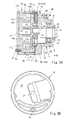
Fig. 3] Fig. 3A is a cross-sectional view showing the constitution ranging from the fixed scroll member to the block member which is housed in a housing of the scroll-type compressor taken along a line B-B inFig. 5 andFig. 6B .Fig. 3B is a view of the fixed scroll member shown inFig. 3A as viewed in the axial direction. - [
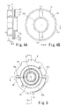
Fig. 4] Fig. 4A and Fig. 4B are views showing an orbiting scroll member, whereinFig. 4A is a cross-sectional view taken along a line B-B inFig. 4B and Fig. 5, and Fig. 4B is a view of a side of the orbiting scroll member which faces a thrust race in an opposed manner as viewed in the axis direction. - [
Fig. 5] Fig. 5 is a view showing a side of the block member which faces the thrust race in an opposed manner as viewed in the axial direction. - [
Fig. 6] Fig. 6A is a cross-sectional view showing the constitution ranging from the orbiting scroll member to the block member shown inFig. 3A taken along a line B-B inFig. 5 andFig. 6B. Fig. 6B is a view as viewed from a line A-A inFig. 6A . - Hereinafter, a scroll-type compressor of the invention is explained in conjunction with an embodiment where an electric compressor which is formed of an integral body consisting of a compression mechanism and a motor is used as the scroll-type compressor by reference with attached drawings.
-
Fig. 1 shows anelectric compressor 1 suitable for a refrigerating cycle which uses a refrigerant as a working fluid. In theelectric compressor 1, acompression mechanism 3 and amotor 4 which drives thecompression mechanism 3 are arranged in the inside of ahousing 2 made of an aluminum alloy, wherein thecompression mechanism 3 is arranged on a left side in the drawing, and themotor 4 is arranged on a right side in the drawing. InFig. 1 , a front side of the compressor is arranged on a right side in the drawing, and a rear side of the compressor is arranged on a left side in the drawing. - A
drive shaft 8 is arranged in thehousing 2 in such a manner that thedrive shaft 8 is rotatably supported on a block member (shaft support member) 5 which is fixed to a middle portion of an inner side of thehousing 2 and afront wall portion 2a by way ofbearings - The
compression mechanism 3 is of a scroll type which includes a fixedscroll member 10 and anorbiting scroll member 11 arranged to face the fixedscroll member 10 in an opposed manner. The fixedscroll member 10 is constituted of: a disc-shapedend plate 10a which is fixed to an inner side of a rear portion of thehousing 2; a cylindrical outerperipheral wall 10b which is formed over the whole circumference of theend plate 10a along an outer periphery of theend plate 10a and is raised from theend plate 10a in the frontward direction; and a whirlpool-like spiral wall 10c which extends frontwardly from theend plate 10a inside the outer peripheral wall. - The
orbiting scroll member 11 is constituted of a disc-shapedend plate 11 a and a whirlpool-like spiral wall 11c which is raised from theend plate 11a in the rearward direction. Aneccentric shaft 8a which is formed on a rear end portion of thedrive shaft 8 and is eccentrically arranged from a shaft center of the drive shaft is connected to aboss portion 11b formed on a back surface of theend plate 11a by way of abushing 12 and abearing 13. Accordingly, theorbiting scroll member 11 is supported in an orbiting manner about the shaft center of thedrive shaft 8. - The fixed
scroll member 10 and theorbiting scroll member 11 haverespective spiral walls end plate compression chamber 15 is defined in a space surrounded by theend plate 10a and thespiral wall 10c of the fixedscroll member 10 and theend plate 11a and thespiral wall 11c of theorbiting scroll member 11. - As shown in
Fig. 2 andFig. 3 , a thin-plate-shapedannular thrust race 16 is sandwiched between the outerperipheral wall 10b of the fixedscroll member 10 and anend surface 5a of theblock member 5, and the fixedscroll member 10 and theblock member 5 are made to abut each other by way of thethrust race 16. - The
thrust race 16 is made of a material possessing excellent wear resistance. Thethrust race 16 is formed into a size such that an outer peripheral shape conforms to an outer peripheral shape of theend surface 5a of theblock member 5 which thethrust race 16 faces in an opposed manner. Acenter hole 16a which allows theboss portion 11b of theorbiting scroll member 11 to pass there through is formed in a center portion of thethrust race 16. The fixedscroll member 10, thethrust race 16 and theblock member 5 are positioned and fixed by positioningpins 9 which are inserted intopin insertion holes 16c formed in thethrust race 16.
As also shown inFig. 4 , a recessedportion 11d is formed on a back surface of theorbiting scroll member 11 in such a manner that a portion ranging from a periphery to theboss portion 11b is slightly (by approximately 0.5mm, for example) indented (decreasing a thickness of the end plate) while leaving the periphery having a predetermined width (for example, approximately 2mm). Thethrust race 16 allows theboss portion 11b of theorbiting scroll member 11 to pass through thecenter hole 16a thereof, and is brought into close contact with the whole circumference of a back surface of theorbiting scroll member 11. Accordingly, on the back surface of theend plate 11a of theorbiting scroll member 11, anannular slide surface 11f having a predetermined width is formed on the periphery of theend plate 11a in such a manner that theannular slide surface 11f surrounds the recessedportion 11d.
Theslide surface 11f of theorbiting scroll member 11 is formed such that theslide surface 11f does not cross thecenter hole 16a andcutaway portions 16b formed in thethrust race 16 during the orbiting movement of the orbiting scroll member 11 (such that thecenter hole 16a and thecutaway portions 16b are always arranged inside theslide surface 11f), and theslide surface 11f is brought into slide contact with thethrust race 16 such that theslide surface 11f does not go beyond or project from thethrust race 16.
Further,key groove portions 11e which extend in the radial direction are formed on the recessedportion 11d. Thekey groove portions 11e formed on the recessedportion 11d are formed so as not to go beyond (penetrate theslide surface 11f) the periphery of theend plate 11a, and are formed inside theannular slide surface 11f. - The
block member 5 has a throughhole 5b at the center thereof, and is formed into a cylindrical shape such that a diameter of an inner surface of theblock member 5 is stepwisely increased. In theblock member 5, from a front side remotest from thethrust race 16, a sealingmember accommodating portion 22 which accommodates a sealingmember 21 for sealing a gap between theblock member 5 and thedrive shaft 8 therein, a bearingaccommodating portion 23 which accommodates thebearing 6 therein, aweight accommodating portion 24 which accommodates abalance weight 19 which is integrally formed with thebushing 12 and is rotated along with the rotation of thedrive shaft 8 therein, and an Oldhamaccommodating portion 25 which is formed from theend surface 5a of theblock member 5 and accommodates anOldham ring 18 described later between theOldham accommodating portion 25 and thethrust race 16 are formed. - A rotation prevention mechanism of the
orbiting scroll member 11 is constituted of the Oldham ring (rotation prevention member) 18, and theorbiting scroll member 11 and theblock member 5 with which theOldham ring 18 is engaged. TheOldham ring 18 is an integral body formed of aring portion 18a which is formed into an annular shape so as to allow the boss portion of the orbiting scroll member to pass there through, a pair ofkey portions 18b which is formed on thering portion 18a in a projecting manner in the normal direction from anorbiting scroll member 11 side, and a pair ofkey portions 18c which is formed on thering portion 18a in an extending manner in an arm shape in the radial direction. Thekey portions 18b are formed at two positions displaced from each other by 180 degrees in phase, while thekey portions 18c are formed at two positions displaced from each other by 180 degrees in phase and are also formed in a displaced manner from thekey portions 18b by 90 degrees (thekey portions 18b and thekey portions 18c being formed such that a line which connects the pair ofkey portions 18b and a line which connects the pair ofkey portions 18c become orthogonal to each other). - The
key portions 18b are configured such that thekey portions 18b pass through thecutaway portions 16b which extend upwardly and downwardly in the drawing from thecenter hole 16a formed in thethrust race 16 respectively, are slidably engaged with thekey groove portions 11e which are formed on the recessedportion 11d of theorbiting scroll member 11 in a radially extending manner with a minute clearance there between, and are movable only in the extending direction of thekey groove portions 11e (in this embodiment, in the vertical direction). - As also shown in
Fig. 5 , theOldham accommodating portion 25 which is formed on theblock member 5 so as to accommodate theOldham ring 18 is constituted of a circular ringportion accommodating portion 25a which is formed on a thrust-race-side opening end of theblock member 5, andkey groove portions portion accommodating portion 25a. Thering portion 18a of theOldham ring 18 is accommodated in the ringportion accommodating portion 25a in a state where the movement of thering portion 18a in the extending direction of thekey portions 18c is allowed. The pair ofkey portions 18c is slidably engaged with thekey groove portions key portions 18c are movable only in the extending direction of thekey groove portions - Accordingly, although a rotational force is generated in the
orbiting scroll member 11 due to the rotation of thedrive shaft 8, since the pair ofkey portions 18b of theOldham ring 18 slides in the pair ofkey groove portions 11e formed on theorbiting scroll member 11 in a reciprocating manner, and the pair ofkey portions 18c slides in the pair ofkey groove portions block member 5 in a reciprocating manner, theorbiting scroll member 11 performs an orbiting movement with respect to the shaft center of thedrive shaft 8 in a state where the rotation of theorbiting scroll member 11 is prevented. - The
center hole 16a formed in thethrust race 16 is formed with a size such that thecenter hole 16a allows theboss portion 11b of the orbiting scroll member to pass there through but does not allow thering portion 18a of theOldham ring 18 to pass there through, and thering portion 18a of theOldham ring 18 can be brought into slide contact with the periphery of a block-side end surface of thethrust race 16 around the center hole. Thecutaway portions 16b which allow thekey portions 18b to pass there through are formed within a movable range of thekey portions 18b by taking into account the movement of theOldham ring 18. - The
thrust race 16 is brought into close contact with the end surface of theblock member 5 so as to close thekey groove portions Oldham accommodating portion 25. That is, thethrust race 16 is brought into close contact with the end surface of theblock member 5 to areas outside thekey groove portions block member 5 in the radial direction, and theOldham accommodating portion 25 of theblock member 5 is formed inside the close contact portion between thethrust race 16 and theblock member 5. In this embodiment, thethrust race 16 is formed with a size where an outer edge of thethrust race 16 conforms with a shape of the end surface of theblock member 5 and hence, the thrust race is brought into close contact with the whole surface of the end surface of theblock member 5 whereby an introducing groove 38 of apressure supply passage 45 described later is also closed simultaneously.
While thedrive shaft 8 is allowed to pass through theblock member 5 by way of thebearing 6, the sealingmember 21 is arranged in the sealingmember accommodating portion 22 of theblock member 5 so that a gap defined between thedrive shaft 8 and theblock member 5 is hermetically sealed by the sealingmember 21. - Accordingly, a front side of the
thrust race 16 is brought into close contact with the end surface of theblock member 5, a back side of thethrust race 16 is brought into close contact with the whole circumference of theslide surface 11f of theorbiting scroll member 11 and hence, aretention space 50 is formed of a region surrounded by theorbiting scroll member 11, thethrust race 16 and theblock member 5. - An
intake chamber 26 which sucks a refrigerant introduced from anintake port 40 described later through anintake passage 41 is formed between the outerperipheral wall 10b of the above-mentionedfixed scroll member 10 and the outermost peripheral portion of thespiral wall 11c of theorbiting scroll member 11. In the inside of the housing, on a back side of the fixedscroll member 10, adischarge chamber 28 is formed between thefixed scroll member 10 and therear side wall 2b of thehousing 2. A refrigerant gas compressed in thecompression chamber 15 is discharged into thedischarge chamber 28 through adischarge hole 27 formed in an approximately center portion of the fixedscroll member 10. Oil contained in the refrigerant gas discharged into thedischarge chamber 28 is separated from the gas to some extent in thedischarge chamber 28, and is supplied under pressure to an external refrigerant circuit from a discharge port not shown in the drawing. Separated oil and a refrigerant mixed with oil are also accumulated in areservoir chamber 31 which is arranged below thedischarge chamber 28. A high pressure region is formed of thedischarge chamber 28 and thereservoir chamber 31. - On the other hand, in the inside of the
housing 2, amotor accommodating space 32 which accommodates themotor 4 therein is formed in front of theblock member 5, and astator 33 which constitutes themotor 4 is fixedly mounted in themotor accommodating space 32. Thestator 33 is constituted of aniron core 34 having a cylindrical shape and acoil 35 which is wound around theiron core 34, and is fixed to an inner surface of thehousing 2. Arotor 36 which is rotatably accommodated in the inside of thestator 33 and is formed of a magnet is fixedly mounted on thedrive shaft 8. Therotor 36 is configured to be rotated by a rotary magnetic force generated by thestator 33 along with the rotation of thedrive shaft 8. Themotor 4 formed of a brushless DC motor is constituted of thestator 33 and therotor 36. - The
intake port 40 through which a refrigerant gas is sucked is formed in a side surface of thehousing 2 which faces themotor accommodating space 32 in an opposed manner. Anintake passage 41 is formed in such a manner that a refrigerant which flows into themotor accommodating space 32 from theintake port 40 is introduced into theintake chamber 26 through a gap which is formed between thestator 33 and thehousing 2, a gap not shown in the drawing which is formed between theblock member 5 and thehousing 2, and a gap which is formed between thefixed scroll member 10 and thehousing 2. - A
passage 42 is formed in a lower portion of the fixedscroll member 10. That is, thepassage 42 which has one end thereof opened in thereservoir chamber 31 constituting a portion of the discharge region and has the other end thereof opened on an end surface of the fixedscroll member 10 which faces thethrust race 16 in an opposed manner is formed in theend plate 10a and the outerperipheral wall 10b of the fixedscroll member 10. A throughhole 43 is formed in thethrust race 16 at a position which faces an opening portion of thepassage 42. Further, an introducinggroove 44 is formed on an end surface of theblock member 5 which faces thethrust race 16 in an opposed manner in such a manner that the introducinggroove 44 is formed along an outer periphery of theblock member 5 ranging from a position which faces the throughhole 43 formed in thethrust race 16 to onekey groove portion 25b. - Due to such a constitution, the discharge region is communicated with one
key groove portion 25b through thepassage 42, the throughhole 43 and the introducinggroove 44, and apressure supply passage 45 which makes the discharge region and theOldham accommodating portion 25 communicate with each other is constituted of thepassage 42, the throughhole 43 and the introducinggroove 44. Further, anorifice 46 is formed in a middle portion of thepressure supply passage 45, in this embodiment, in the vicinity of an end portion of thepressure supply passage 45 which opens in thereservoir chamber 31, and afilter 47 is arranged upstream of theorifice 46. - A
pressure release passage 48 is formed in theblock member 5, wherein thepressure release passage 48 has one end thereof opened in the otherkey groove portion 25c and has the other end thereof opened on a back surface of theblock member 5 at a position which faces the motor accommodating space 32 (intake passage). Further, apressure regulating valve 49 which releases a pressure to theintake passage 41 when a pressure in theretention space 50 becomes a predetermined pressure or more is mounted in a middle portion of thepressure release passage 48, for example, on an open end portion of theintake passage 41. Accordingly, in this embodiment, a pressure in theretention space 50 is set to an intermediate pressure between a pressure of a working fluid which is introduced into thecompression chamber 15 and a pressure of the working fluid discharged from thecompression chamber 15. It is desirable that such an intermediate pressure is set to be large within a range where a compression reaction force which thethrust race 16 receives from theorbiting scroll member 11 can be reduced. However, when the intermediate pressure is excessively large, a so-called turnover phenomenon where theorbiting scroll member 11 is inclined occurs and hence, the intermediate pressure is set to a value which falls within a range where such a turnover phenomenon does not occur, for example, a range from 0.02 to 0.05MPa. -
Symbol 51 indicates an inverter drive circuit which is mounted on an invertercircuit end plate 53 accommodated in aninverter accommodating chamber 52 formed on an upper portion of thehousing 2. The inverter drive circuit is provided for controlling the supply of electric power to themotor 4. An inverter-side cluster 55 is connected to theinverter drive circuit 51 via acable 54, a motor-side cluster 58 is connected to thestator 33 via acable 57, the inverter-side cluster 55 is mounted on a relay terminal (air-tight terminal) 56 which is mounted on a rear portion of theinverter accommodating chamber 52 of thehousing 2 from above, and the motor-side cluster 58 is mounted on therelay terminal 56 from below. Due to such a constitution, theinverter drive circuit 51 and thestator 33 are electrically connected to each other via therelay terminal 56 thus supplying electric power to themotor 4 from theinverter drive circuit 51. - Due to such a constitution, when the
motor 4 is rotated so that thedrive shaft 8 is rotated, in thecompression mechanism 3, theorbiting scroll member 11 is rotated about theeccentric shaft 8a and hence, theorbiting scroll member 11 orbits about the shaft center of the fixedscroll member 10. In such an operation, the rotation of theorbiting scroll member 11 is prevented by the rotation prevention mechanism constituted of theOldham ring 18 and hence, only the orbiting movement is allowed. - Due to the orbiting movement of the
orbiting scroll member 11, thecompression chamber 15 moves from an outer peripheral side to a center side of thespiral walls compression chamber 15 from theintake chamber 26 is compressed, and the compressed refrigerant gas is discharged into thedischarge chamber 28 through thedischarge hole 27 formed in theend plate 10a of the fixedscroll member 10. Then, the refrigerant gas is fed to an external refrigerant circuit through the discharge port not shown in the drawing. - Lubrication oil which is mixed to the refrigerant gas discharged into the
discharge chamber 28 is separated from the refrigerant gas to some extent in thedischarge chamber 28, the separated lubrication oil is supplied to thekey groove portion 25b formed on theOldham accommodating portion 25 of theblock member 5 together with the refrigerant through thepressure supply passage 45 on which theorifice 46 is mounted, and is introduced into theretention space 50 arranged on a back side of theorbiting scroll member 11. Thereafter, the lubrication oil traverses theretention space 50 from onekey groove portion 25b to the otherkey groove portion 25c, and is released into theintake passage 41 from thepressure release passage 48 formed in the otherkey groove portion 25c through thepressure regulating valve 49. - Due to such a constitution, the
retention space 50 is formed by bringing the periphery of theorbiting scroll member 11 and the end surface of theblock member 5 into close contact with thethrust race 16. Accordingly, it is possible to retain oil or a working fluid (refrigerant) mixed with oil supplied from thecompression chamber 15 in theretention space 50 and hence, it is possible to supply an abundant amount of oil to the slide portions of theOldham ring 18. Accordingly, the lubrication of the Oldham ring can be surely performed thus ensuring the reliability of the rotation prevention mechanism. - The
pressure regulating valve 49 which is mounted in thepressure release passage 48 opens when the pressure becomes a predetermined pressure or more and releases a medium accumulated in theretention space 50 into the intake passage 41 (motor accommodating space 32). Accordingly, a retention state of a medium in theretention space 50 can be regulated by thepressure regulating valve 49, and a pressure in theretention space 50 can be set to an intermediate pressure.
Accordingly, an amount of oil to be retained in the retention space can be regulated by thepressure regulating valve 49, and an intermediate pressure is applied to theorbiting scroll member 11 from a back side of theorbiting scroll member 11 and hence, a compression reaction force which acts on theorbiting scroll member 11 can be decreased with the use of the intermediate pressure of theretention space 50. - That is, by regulating a valve opening pressure of the
pressure regulating valve 49, the smooth movement of the Oldham ring can be ensured, and a load applied to thethrust race 16 can be reduced within a range where the turnover of theorbiting scroll member 11 does not occur (a biasing force by which theorbiting scroll member 11 is pushed to thethrust race 16 can be attenuated). Accordingly, wear on a slide contact portion between the orbitingscroll member 11 and thethrust race 16 can be reduced. - Further, according to the above-mentioned constitution, the
thrust race 16 is interposed between thefixed scroll member 10 and theblock member 5, and theorbiting scroll member 11 is brought into contact with thethrust race 16. Accordingly, it is no more necessary to cover a compression space in the fixedscroll member 10 with theend plate 11 a of theorbiting scroll member 11 for increasing a back pressure of theorbiting scroll member 11, so that an outer diameter of theorbiting scroll member 11 can be decreased thus eventually decreasing an outer diameter of the compressor. Still further, theOldham ring 18 is held between theblock member 5 and thethrust race 16 thus covering theOldham accommodating portion 25 with theblock member 5 and thethrust race 16 and hence, it is possible to suppress fluttering of theOldham ring 18. - According to the above-mentioned constitution, oil or a refrigerant mixed with oil which is separated in the compression chamber is supplied to one
key groove portion 25b of theOldham accommodating portion 25 which accommodates theOldham ring 18 through thepressure supply passage 45 and, thereafter, is fed to the otherkey groove portion 25c through the ringportion accommodating portion 25a and, thereafter, is discharged to theintake passage 41 through thepressure release passage 48. Accordingly, the passage which can supply an abundant amount of oil to the slide contact portion between theOldham ring 18 and thethrust race 16, the slide contact portion between the orbitingscroll member 11 and thethrust race 16, thebearing 13 and the like can be positively formed and hence, a favorable lubrication state can be acquired irrespective of an installed state of the compressor. - In the above-mentioned constitution, oil is naturally separated from a refrigerant which is discharged to the
discharge chamber 28, and the separated oil or the refrigerant mixed with oil is supplied to theretention space 50. However, it may be possible to adopt the constitution where an oil separator which separates oil in a refrigerant discharged to the discharge chamber is further provided, oil separated by the oil separator is accumulated in thereservoir chamber 31, and only oil is supplied to theretention space 50.
Further, with respect to the above-mentioned constitution, the case where the pressure in the retention space is set to an intermediate pressure is exemplified. However, any constitution is adopted provided that a medium compressed in the compression chamber can be temporarily retained in theretention space 50. That is, it is possible to adopt the constitution where thepressure regulating valve 49 is removed from thepressure release passage 48 and a medium is temporarily retained in the retention space by making use of passage resistance of the pressure release passage per se. Alternatively, it may be possible to adopt the constitution where a pressure is discharged to theintake passage 41 through thebearing 6 by eliminating thepressure release passage 48 and the sealingmember 21, and a medium is temporarily retained by making use of passage resistance when the medium passes through an area in the vicinity of thebearing 6.
Further, with respect to the above-mentioned constitution, the case where theblock member 5 is constituted as the member fixed to the housing is exemplified. However, theblock member 5 may be integrally formed with the housing by molding. -
- 1:
- electric compressor
- 2:
- housing
- 4:
- motor
- 5:
- block member
- 8:
- drive shaft
- 10:
- fixed scroll member
- 11:
- orbiting scroll member
- 11a:
- end plate
- 11d:
- recessed portion
- 11f:
- slide surface
- 15:
- compression chamber
- 16:
- thrust race
- 18:
- Oldham ring
- 18a:
- ring portion
- 18b, 18c:
- key portion
- 11d, 25b:
- key groove portion
- 25:
- Oldham accommodating portion
- 50:
- retention space
- 41:
- intake passage
- 28:
- discharge chamber
- 45:
- pressure supply passage
- 48:
- pressure release passage
- 49:
- pressure regulating valve
Claims (5)
the discharge region and the retention space are communicated with each other through a pressure supply passage having a throttle formed in a middle portion thereof.
the Oldham accommodating portion is constituted of a ring portion accommodating portion which accommodates the ring portion therein, and a pair of key groove portions which is communicated with the ring portion accommodating portion and with which the pair of key portions formed on both sides of the ring portion in the radial direction in a projecting manner is slidably engaged, and
the pressure supply passage is communicated with one of the pair of key groove portions formed on the block member, and the pressure release passage is communicated with the other of the pair of key groove portions formed on the block member.
Applications Claiming Priority (2)
| Application Number | Priority Date | Filing Date | Title |
|---|---|---|---|
| JP2010210312A JP5612411B2 (en) | 2010-09-21 | 2010-09-21 | Scroll compressor |
| PCT/JP2011/005156 WO2012039109A1 (en) | 2010-09-21 | 2011-09-14 | Scroll type compressor |
Publications (2)
| Publication Number | Publication Date |
|---|---|
| EP2631484A1 true EP2631484A1 (en) | 2013-08-28 |
| EP2631484A4 EP2631484A4 (en) | 2015-11-04 |
Family
ID=45873613
Family Applications (1)
| Application Number | Title | Priority Date | Filing Date |
|---|---|---|---|
| EP11826560.2A Pending EP2631484A4 (en) | 2010-09-21 | 2011-09-14 | SCROLL COMPRESSORS |
Country Status (5)
| Country | Link |
|---|---|
| US (1) | US20130280115A1 (en) |
| EP (1) | EP2631484A4 (en) |
| JP (1) | JP5612411B2 (en) |
| CN (1) | CN103109089B (en) |
| WO (1) | WO2012039109A1 (en) |
Cited By (1)
| Publication number | Priority date | Publication date | Assignee | Title |
|---|---|---|---|---|
| EP3722607A4 (en) * | 2018-01-17 | 2020-11-18 | Daikin Industries, Ltd. | SCROLL COMPRESSORS |
Families Citing this family (26)
| Publication number | Priority date | Publication date | Assignee | Title |
|---|---|---|---|---|
| FR2998340A1 (en) * | 2012-11-19 | 2014-05-23 | Danfoss Commercial Compressors | SPIRAL COMPRESSOR WITH VARIABLE SPEED. |
| JP6120982B2 (en) * | 2013-10-25 | 2017-04-26 | 三菱電機株式会社 | Scroll fluid machinery |
| KR101942914B1 (en) | 2014-01-08 | 2019-01-29 | 한온시스템 주식회사 | Compressor |
| CN104863859B (en) * | 2014-02-25 | 2017-02-15 | 艾默生环境优化技术(苏州)有限公司 | Movable scroll for scroll compressor and scroll compressor |
| JPWO2015155802A1 (en) * | 2014-04-09 | 2017-04-13 | 三菱電機株式会社 | Scroll compressor |
| KR102291952B1 (en) | 2015-03-04 | 2021-08-23 | 한온시스템 주식회사 | A eccentric bush assembling structure of a scroll compressor |
| DE102015120151A1 (en) | 2015-11-20 | 2017-05-24 | OET GmbH | Displacement machine according to the spiral principle, method for operating a positive displacement machine, vehicle air conditioning and vehicle |
| JP2017115762A (en) * | 2015-12-25 | 2017-06-29 | サンデンホールディングス株式会社 | Scroll compressor |
| CN107120283B (en) * | 2016-02-24 | 2020-12-15 | 上海海立新能源技术有限公司 | Prevent from change ring and scroll compressor |
| KR102485660B1 (en) | 2016-10-04 | 2023-01-09 | 한온시스템 주식회사 | Scroll compressor |
| DE102017110913B3 (en) * | 2017-05-19 | 2018-08-23 | OET GmbH | Displacement machine according to the spiral principle, method for operating a positive displacement machine, vehicle air conditioning and vehicle |
| JP6947106B2 (en) * | 2018-03-30 | 2021-10-13 | 株式会社豊田自動織機 | Scroll compressor |
| JP7076536B2 (en) * | 2018-04-27 | 2022-05-27 | 三菱電機株式会社 | Scroll compressor |
| KR102478905B1 (en) | 2018-07-18 | 2022-12-20 | 한온시스템 주식회사 | Scroll compressor |
| KR102480987B1 (en) | 2018-09-14 | 2022-12-26 | 한온시스템 주식회사 | Scroll compressor |
| KR102503234B1 (en) | 2018-11-30 | 2023-02-24 | 한온시스템 주식회사 | Scroll compressor |
| JPWO2020250698A1 (en) * | 2019-06-11 | 2020-12-17 | ||
| KR102687327B1 (en) | 2019-07-22 | 2024-07-23 | 한온시스템 주식회사 | Scroll compressor |
| JP2021116731A (en) * | 2020-01-24 | 2021-08-10 | パナソニックIpマネジメント株式会社 | Scroll compressor |
| DE102020117373A1 (en) * | 2020-07-01 | 2022-01-05 | Hanon Systems | Scroll compressor for compressing a refrigerant and process for oil enrichment and distribution |
| US12203473B2 (en) * | 2020-10-08 | 2025-01-21 | Pierburg Gmbh | Filter-and-throttle unit for a scroll compressor, and scroll compressor for a refrigerant circuit |
| KR102861984B1 (en) | 2020-12-23 | 2025-09-19 | 한온시스템 주식회사 | Scroll compressor |
| KR102936118B1 (en) | 2022-03-22 | 2026-03-09 | 한온시스템 주식회사 | Scroll compressor |
| KR20240052145A (en) | 2022-10-13 | 2024-04-23 | 한온시스템 주식회사 | Scroll compressor |
| KR20250047474A (en) | 2023-09-27 | 2025-04-04 | 한온시스템 주식회사 | Scroll compressor |
| WO2025164819A1 (en) * | 2024-01-30 | 2025-08-07 | 엘지전자 주식회사 | Scroll compressor |
Family Cites Families (17)
| Publication number | Priority date | Publication date | Assignee | Title |
|---|---|---|---|---|
| JPS55109793A (en) * | 1979-02-17 | 1980-08-23 | Sanden Corp | Displacement type fluid compressor |
| JPS61118580A (en) * | 1984-11-15 | 1986-06-05 | Matsushita Electric Ind Co Ltd | scroll compressor |
| JP2631839B2 (en) * | 1986-08-22 | 1997-07-16 | 株式会社日立製作所 | Scroll compressor |
| KR950008694B1 (en) * | 1987-12-28 | 1995-08-04 | 마쯔시다덴기산교 가부시기가이샤 | Scroll compressor |
| JPH0719185A (en) * | 1993-06-30 | 1995-01-20 | Sanyo Electric Co Ltd | Scroll type air compressor |
| TW316940B (en) * | 1994-09-16 | 1997-10-01 | Hitachi Ltd | |
| JP3533739B2 (en) * | 1995-01-17 | 2004-05-31 | 株式会社日立製作所 | Scroll fluid machine |
| JPH08151983A (en) * | 1994-11-30 | 1996-06-11 | Matsushita Electric Ind Co Ltd | Scroll compressor |
| JPH08159055A (en) * | 1994-12-08 | 1996-06-18 | Sanden Corp | High pressure type compressor |
| JPH08219061A (en) | 1995-02-16 | 1996-08-27 | Zexel Corp | Scroll type compressor |
| JP2778585B2 (en) * | 1996-06-14 | 1998-07-23 | 松下電器産業株式会社 | Scroll gas compressor |
| WO1999063227A1 (en) * | 1997-06-03 | 1999-12-09 | Matsushita Electric Industrial Co., Ltd. | Scroll compressor |
| JP4123551B2 (en) * | 1997-11-17 | 2008-07-23 | 株式会社日立製作所 | Scroll compressor |
| WO2005001292A1 (en) * | 2003-06-17 | 2005-01-06 | Matsushita Electric Industrial Co., Ltd. | Scroll compressor |
| JP2006266123A (en) | 2005-03-23 | 2006-10-05 | Matsushita Electric Ind Co Ltd | Scroll compressor |
| TWI353418B (en) * | 2007-12-25 | 2011-12-01 | Ind Tech Res Inst | Scroll compressor |
| JP5201113B2 (en) * | 2008-12-03 | 2013-06-05 | 株式会社豊田自動織機 | Scroll compressor |
-
2010
- 2010-09-21 JP JP2010210312A patent/JP5612411B2/en not_active Expired - Fee Related
-
2011
- 2011-09-14 WO PCT/JP2011/005156 patent/WO2012039109A1/en not_active Ceased
- 2011-09-14 US US13/825,506 patent/US20130280115A1/en not_active Abandoned
- 2011-09-14 EP EP11826560.2A patent/EP2631484A4/en active Pending
- 2011-09-14 CN CN201180044759.4A patent/CN103109089B/en not_active Expired - Fee Related
Cited By (2)
| Publication number | Priority date | Publication date | Assignee | Title |
|---|---|---|---|---|
| EP3722607A4 (en) * | 2018-01-17 | 2020-11-18 | Daikin Industries, Ltd. | SCROLL COMPRESSORS |
| US11333147B2 (en) | 2018-01-17 | 2022-05-17 | Daikin Industries, Ltd. | Scroll compressor including an orbiting scroll having an orbiting end plate provided with a rear concave portion |
Also Published As
| Publication number | Publication date |
|---|---|
| CN103109089A (en) | 2013-05-15 |
| WO2012039109A1 (en) | 2012-03-29 |
| US20130280115A1 (en) | 2013-10-24 |
| EP2631484A4 (en) | 2015-11-04 |
| CN103109089B (en) | 2017-02-22 |
| JP5612411B2 (en) | 2014-10-22 |
| JP2012067602A (en) | 2012-04-05 |
Similar Documents
| Publication | Publication Date | Title |
|---|---|---|
| US20130280115A1 (en) | Scroll Type Compressor | |
| JP5315933B2 (en) | Electric scroll compressor | |
| EP2730742B1 (en) | Scroll compressor with rotation restriction mechanism | |
| EP2781755B1 (en) | Scroll compressor with back pressure chamber | |
| EP1679441B1 (en) | Scroll compressor | |
| US20180223849A1 (en) | Scroll compressor with axial flux motor | |
| EP2618000B1 (en) | Differential pressure regulating valve and motor-driven compressor having differential pressure regulating device | |
| JP5516651B2 (en) | Scroll compressor | |
| JP7349279B2 (en) | scroll compressor | |
| JP6738176B2 (en) | Scroll compressor | |
| WO2017163814A1 (en) | Scroll-type compressor | |
| JP2012132409A (en) | Scroll compressor | |
| CN100464075C (en) | scroll compressor | |
| JP2021032108A (en) | Scroll type compressor | |
| JP2018141427A (en) | Hermetic scroll compressor | |
| KR101955985B1 (en) | Motor-operated compressor | |
| US20190309749A1 (en) | Motor operated compressor | |
| JP4277995B2 (en) | Electric compressor and manufacturing method thereof | |
| JP2023165449A (en) | compressor | |
| JP6961413B2 (en) | Scroll type fluid machine | |
| WO2017163812A1 (en) | Refrigerant compressor | |
| WO2020189602A1 (en) | Scroll compressor | |
| JP7468428B2 (en) | Scroll Compressor | |
| JP2021021345A (en) | Scroll-type compressor | |
| JP4961178B2 (en) | Hermetic scroll compressor |
Legal Events
| Date | Code | Title | Description |
|---|---|---|---|
| PUAI | Public reference made under article 153(3) epc to a published international application that has entered the european phase |
Free format text: ORIGINAL CODE: 0009012 |
|
| 17P | Request for examination filed |
Effective date: 20130419 |
|
| AK | Designated contracting states |
Kind code of ref document: A1 Designated state(s): AL AT BE BG CH CY CZ DE DK EE ES FI FR GB GR HR HU IE IS IT LI LT LU LV MC MK MT NL NO PL PT RO RS SE SI SK SM TR |
|
| DAX | Request for extension of the european patent (deleted) | ||
| RA4 | Supplementary search report drawn up and despatched (corrected) |
Effective date: 20151002 |
|
| RIC1 | Information provided on ipc code assigned before grant |
Ipc: F04C 18/02 20060101AFI20150928BHEP |
|
| 18D | Application deemed to be withdrawn |
Effective date: 20160503 |
|
| STAA | Information on the status of an ep patent application or granted ep patent |
Free format text: STATUS: REQUEST FOR EXAMINATION WAS MADE |
|
| D18D | Application deemed to be withdrawn (deleted) | ||
| STAA | Information on the status of an ep patent application or granted ep patent |
Free format text: STATUS: THE APPLICATION IS DEEMED TO BE WITHDRAWN |
|
| R18D | Application deemed to be withdrawn (corrected) |
Effective date: 20160503 |