EP2631448A1 - Verfahren zum Betreiben einer mit wenigstens einer gespülten Vorkammer versehenen Brennkraftmaschine - Google Patents
Verfahren zum Betreiben einer mit wenigstens einer gespülten Vorkammer versehenen Brennkraftmaschine Download PDFInfo
- Publication number
- EP2631448A1 EP2631448A1 EP13000705.7A EP13000705A EP2631448A1 EP 2631448 A1 EP2631448 A1 EP 2631448A1 EP 13000705 A EP13000705 A EP 13000705A EP 2631448 A1 EP2631448 A1 EP 2631448A1
- Authority
- EP
- European Patent Office
- Prior art keywords
- prechamber
- combustion chamber
- main combustion
- medium
- chamber
- Prior art date
- Legal status (The legal status is an assumption and is not a legal conclusion. Google has not performed a legal analysis and makes no representation as to the accuracy of the status listed.)
- Granted
Links
Images

Classifications
-
- F—MECHANICAL ENGINEERING; LIGHTING; HEATING; WEAPONS; BLASTING
- F02—COMBUSTION ENGINES; HOT-GAS OR COMBUSTION-PRODUCT ENGINE PLANTS
- F02B—INTERNAL-COMBUSTION PISTON ENGINES; COMBUSTION ENGINES IN GENERAL
- F02B17/00—Engines characterised by means for effecting stratification of charge in cylinders
- F02B17/005—Engines characterised by means for effecting stratification of charge in cylinders having direct injection in the combustion chamber
-
- F—MECHANICAL ENGINEERING; LIGHTING; HEATING; WEAPONS; BLASTING
- F02—COMBUSTION ENGINES; HOT-GAS OR COMBUSTION-PRODUCT ENGINE PLANTS
- F02B—INTERNAL-COMBUSTION PISTON ENGINES; COMBUSTION ENGINES IN GENERAL
- F02B19/00—Engines characterised by precombustion chambers
- F02B19/12—Engines characterised by precombustion chambers with positive ignition
-
- F—MECHANICAL ENGINEERING; LIGHTING; HEATING; WEAPONS; BLASTING
- F02—COMBUSTION ENGINES; HOT-GAS OR COMBUSTION-PRODUCT ENGINE PLANTS
- F02M—SUPPLYING COMBUSTION ENGINES IN GENERAL WITH COMBUSTIBLE MIXTURES OR CONSTITUENTS THEREOF
- F02M25/00—Engine-pertinent apparatus for adding non-fuel substances or small quantities of secondary fuel to combustion-air, main fuel or fuel-air mixture
- F02M25/022—Adding fuel and water emulsion, water or steam
- F02M25/025—Adding water
- F02M25/03—Adding water into the cylinder or the pre-combustion chamber
-
- Y—GENERAL TAGGING OF NEW TECHNOLOGICAL DEVELOPMENTS; GENERAL TAGGING OF CROSS-SECTIONAL TECHNOLOGIES SPANNING OVER SEVERAL SECTIONS OF THE IPC; TECHNICAL SUBJECTS COVERED BY FORMER USPC CROSS-REFERENCE ART COLLECTIONS [XRACs] AND DIGESTS
- Y02—TECHNOLOGIES OR APPLICATIONS FOR MITIGATION OR ADAPTATION AGAINST CLIMATE CHANGE
- Y02T—CLIMATE CHANGE MITIGATION TECHNOLOGIES RELATED TO TRANSPORTATION
- Y02T10/00—Road transport of goods or passengers
- Y02T10/10—Internal combustion engine [ICE] based vehicles
- Y02T10/12—Improving ICE efficiencies
Definitions
- the invention relates to a method for operating a provided with at least one purged combustion chamber internal combustion engine, wherein the at least one prechamber is connected to a main combustion chamber of the internal combustion engine and wherein - during a flame in the main combustion chamber immediately preceding compression phase - after ignition in the pre-chamber in a first Overflow phase Gas from the antechamber into the main combustion chamber overflowed.
- boosters usually serve pre-chambers, wherein the highly compressed at the end of the compression stroke fuel-air mixture is ignited in a partitioned from the main combustion chamber of the cylinder relatively small side room.
- a main combustion chamber is limited by the working piston, the cylinder liner and the cylinder head base, wherein the secondary chamber (the antechamber) is connected by one or more overflow holes with the main combustion chamber.
- antechambers are during the charge cycle with Propellant purged or filled to grease the fuel-air mixture and thus improve the flame and combustion properties.
- a small amount of propellant gas is diverted from the propellant gas supply to the main combustion chamber and introduced via a suitable, provided with a check valve supply device in the antechamber. This amount of propellant flushes during the charge cycle the antechamber and is therefore often referred to as purge gas.
- the very lean fuel-air mixture of the main combustion chamber flows through the overflow holes in the antechamber and mixes there with the purge gas.
- the ratio of fuel to air in the mixture is given in the form of the excess air coefficient ⁇ .
- Large gas engines are usually operated lean at full load at a ⁇ of about 1.9 to 2.0, that is, the amount of air in the mixture corresponds to about twice the stoichiometric amount of air.
- the object of the invention is to provide an improved method for operating an internal combustion engine, in which the nitrogen oxides formed in the pre-chamber and formed by the prechamber are reduced.
- the performance of the pre-chamber as a booster should not be reduced.
- This object is achieved in that after the first overflow an at least two-phase, incompressible medium - preferably water - is introduced into the prechamber.
- an at least two-phase medium preferably in its liquid state, is introduced into the prechamber.
- the medium is water injected into the prechamber. Due to the evaporation of the medium or of the water in the prechamber, the contents of the prechamber are cooled, resulting in less nitrogen oxides.
- the performance of the prechamber as a booster is not impaired, ie the ignition in the prechamber and also in the main combustion chamber can be at the conventional high Temperatures and thus also be done with the conventional ignition energy.
- the fact that the medium is introduced only after the ignition in the pre-chamber, beyond only relatively small amounts of the medium are necessary to achieve a corresponding cooling and thus a corresponding reduction of nitrogen oxide emissions.
- the medium is introduced into the pre-chamber before reaching the maximum pressure in the main combustion chamber.
- the maximum pressure in the main combustion chamber is reached after exceeding the top dead center of a main combustion chamber limiting piston. Due to the prevailing pressure conditions in the prechamber and in the main combustion chamber during the time window between the first overflow phase and the achievement of the maximum pressure in the main combustion chamber, the introduction of the medium into the prechamber in this time window is particularly advantageous.
- this time window by the compression by means of cylinders in the main combustion chamber at least temporarily back-flowing gas is pushed from the main combustion chamber into the prechamber. It is therefore particularly favorable when gas flowing back from the main combustion chamber flows back into the prechamber in at least one second overflow phase, the medium being introduced at least temporarily during the at least one second overflow phase.
- the prechamber is connected to the main combustion chamber via an overflow channel, wherein the medium is introduced via at least one injection channel which opens into the overflow channel.
- Combustion processes in an internal combustion engine are often controlled as a function of the crankshaft position or depending on the crank angle. Accordingly, it can be provided in an advantageous embodiment of the proposed method that the medium is introduced in a crank angle range of about 15 degrees crank angle before a top dead center of the main combustion chamber bounding piston to about 10 degrees crank angle to the top dead center of the main combustion chamber bounding piston.
- the medium is introduced at a pressure of at least 100 bar, preferably about 200 bar.
- cylinder pressures of about 30 bar to 70 bar may prevail in the combustion chambers (main combustion chamber and prechamber).
- Fig. 1 shows two diagrams.
- the upper diagram shows the course of a differential pressure ⁇ p VH as a function of the crank angle KW.
- the differential pressure ⁇ p VH is to be regarded as the difference between the pressure p V in the prechamber and the pressure p H in the main combustion chamber.
- the illustrated crank angle range KW extends over a complete compression stroke and a complete expansion stroke of a spark-ignition engine-operated spark-ignited gas engine, starting at the bottom dead center BDC of the Main combustion chamber 3 limiting piston 7 (-180 degrees crank angle KW) and also ending in the bottom dead center BDC of the piston 7 (+180 degrees crank angle KW).
- Plotted dashed is also the top dead center 6 (TDC) of the main combustion chamber 3 limiting piston 7 (0 degrees crank angle KW).
- the lower diagram of the Fig. 1 shows the absolute pressure curves of the antechamber pressure p V and the pressure p H in the main combustion chamber.
- the ignition takes place in the pre-chamber 1 (eg by a spark of a spark plug), whereby the pressure p V in the pre-chamber 1 increases more than by the compression due to the expanding gas also increasing pressure p by means of piston 7 H 3 in the main combustion chamber
- the differential pressure profile Ap VH prevails during this crank angle range 4 (first Matterströmphase 4) an excess pressure in the precombustion chamber 1 in relation to the main combustion chamber 3.
- the inflamed fuel-air mixture and the resulting ignition torches from the pre-chamber 1 via one or more overflow channels 8 in the main combustion chamber 3 pressed (see Fig. 2 ).
- These second overflow phases 5 are in particular suitable for introducing the medium M or the water into the prechamber 1, since in these second overflow phases 5 the flow of the backflowing gas G takes place in the direction of the prechamber 1.
- FIG. 1 shown diagrams show the corresponding pressure curves without the proposed introduction of an at least two-phase medium M in the antechamber 1. If, according to the proposed method, a medium M or water is introduced or injected in a second overflow phase 5, the evaporation of the medium M in the prechamber 1 and the associated cooling of the prechamber contents causes the pressure p V in the prechamber 1 to drop additional pressure gradient in the direction of the prechamber 1 arises. The resulting pressure ratios p V , p H thus favoring the introduction of the medium M in the antechamber 1 in addition.
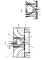
- Fig. 2 shows a prechamber 1 of an internal combustion engine 2.
- the prechamber 1 is connected in this example via a transfer port 8 with a main combustion chamber 3 of the internal combustion engine 2, so that the overall result is a connected volume comprising the prechamber volume and the main combustion chamber volume without interposed valve.
- the main combustion chamber 3 is bounded laterally in this illustration by a cylinder liner 11, above by the bottom of a cylinder head 12 and below by the end face of the piston 7.
- In the overflow channel 8 opens an injection channel 9, through which a medium M - preferably water - can be introduced or injected according to the proposed method in the pre-chamber 1.
- this injection channel 9 can generally also be regarded as a cooling channel for the pre-chamber 1.
- Fig. 3 shows the area marked with a circle Fig. 2 in an enlarged view.
- the considered pre-chamber 1 of the internal combustion engine 2 is in a second overflow phase 5 (see Fig. 1 ).
- the medium M or water is advantageously introduced via the injection channel 9 into the overflow channel 8, as a result of which it subsequently reaches the prechamber 1 and can there lead to a cooling of the prechamber contents.
- the medium M or the water at a pressure of at least 100 bar, preferably about 200 bar, injected.
- about 2 mm 3 to about 5 mm 3 of medium M or water can be introduced per combustion cycle and prechamber 1.
- a retention valve may be arranged, for example, only at a pressure difference of about 10 bar to 20 bar between the pressure in the injection channel 9 and the pressure in the overflow 8 opens to the medium M or to introduce the water into the overflow channel 8.
- a nozzle is arranged at the junction of the injection channel 9 in the overflow 8, through which the medium M or the water can be injected into the overflow 8.
Landscapes
- Engineering & Computer Science (AREA)
- Chemical & Material Sciences (AREA)
- Combustion & Propulsion (AREA)
- Mechanical Engineering (AREA)
- General Engineering & Computer Science (AREA)
- Combustion Methods Of Internal-Combustion Engines (AREA)
Abstract
Description
- Die Erfindung betrifft ein Verfahren zum Betreiben einer mit wenigstens einer gespülten Vorkammer versehenen Brennkraftmaschine, wobei die wenigstens eine Vorkammer mit einem Hauptbrennraum der Brennkraftmaschine verbunden ist und wobei - während einer der Entflammung im Hauptbrennraum unmittelbar vorangehenden Kompressionsphase - nach erfolgter Entflammung in der Vorkammer in einer ersten Überströmphase Gas von der Vorkammer in den Hauptbrennraum überströmt.
- Bei ottomotorisch betriebenen Brennkraftmaschinen, insbesondere bei Gasmotoren, bei denen ein Treibgas-Luft-Gemisch entzündet wird, setzt man bei größeren Brennraumvolumina das Magerkonzept ein. Dies bedeutet, dass ein relativ großer Luftüberschuss vorhanden ist, wodurch bei maximaler Leistungsdichte und gleichzeitig hohem Wirkungsgrad des Motors die Schadstoffemission sowie die thermische Belastung der Bauteile möglichst gering gehalten werden. Die Zündung und Verbrennung sehr magerer Treibstoff-Luft-Gemische stellt dabei eine erhebliche Herausforderung für die Entwicklung bzw. den Betrieb moderner Hochleistungsgasmotoren dar.
- Ab einer gewissen Baugröße der Gasmotoren (meist etwa oberhalb von sechs Litern Hubraum) ist es erforderlich, Zündverstärker einzusetzen, um die entsprechend großen Flammwege in den Brennräumen der Zylinder in möglichst kurzer Zeit zu durchlaufen. Als solche Zündverstärker dienen üblicherweise Vorkammern, wobei das am Ende des Kompressionshubes hoch verdichtete Treibstoff-Luft-Gemisch in einem vom Hauptbrennraum des Zylinders abgeteilten relativ kleinen Nebenraum gezündet wird. Dabei wird ein Hauptbrennraum vom Arbeitskolben, der Zylinderlaufbuchse und dem Zylinderkopfboden begrenzt, wobei der Nebenraum (die Vorkammer) durch eine oder mehrere Überströmbohrungen mit dem Hauptbrennraum verbunden ist. Häufig werden solche Vorkammern während der Ladungswechselphase mit Treibgas gespült bzw. gefüllt, um das Treibstoff-Luft-Gemisch anzufetten und damit die Verflammungs- und Verbrennungseigenschaften zu verbessern. Dazu wird eine kleine Treibgasmenge von der Treibgaszuführung zum Hauptbrennraum abgezweigt und über eine geeignete, mit einem Rückschlagventil versehene Zufuhreinrichtung in die Vorkammer eingeleitet. Diese Treibgasmenge spült während des Ladungswechsels die Vorkammer und wird deshalb oft als Spülgas bezeichnet.
- Während der Kompressionsphase strömt das sehr magere Treibstoff-Luft-Gemisch des Hauptbrennraumes durch die Überströmbohrungen in die Vorkammer und vermischt sich dort mit dem Spülgas. Das Verhältnis von Treibstoff zu Luft im Gemisch wird in Form der Luftüberschusszahl λ angegeben. Eine Luftüberschusszahl von λ = 1 bedeutet dabei, dass die im Gemisch vorhandene Luftmenge genau jener Menge entspricht, die erforderlich ist, um eine vollständige Verbrennung der Treibstoffmenge zu ermöglichen. Die Verbrennung erfolgt in einem solchen Fall stöchiometrisch. Große Gasmotoren werden bei Volllast üblicherweise mager bei einem λ von ca. 1,9 bis 2,0 betrieben, das heißt die Luftmenge im Gemisch entspricht etwa der doppelten stöchiometrischen Luftmenge. Durch die Spülung der Vorkammer mit Treibgas ergibt sich nach Vermischung mit dem Treibgas-Luft-Gemisch aus dem Hauptbrennraum ein mittleres λ in der Vorkammer von ca. 0,8 bis 0,9. Damit ergeben sich optimale Entflammungsbedingungen und aufgrund der Energiedichte intensive, in den Hauptbrennraum austretende Zündfackeln, die zu einem raschen Durchbrennen des Treibstoff-Luft-Gemischs im Hauptbrennraum führen. Bei solchen λ-Werten erfolgt die Verbrennung allerdings auf maximalem Temperaturniveau, sodass auch die Wandtemperaturen im Vorkammerbereich entsprechend hoch sind. Daraus resultieren einerseits eine entsprechend hohe thermische Belastung der Vorkammer und der darin angeordneten Bauteile (z.B. Zündkerze, Ventile) und andererseits unerwünscht hohe Stickoxidemissionen.
- Aus der
JP 07-127453 - Aufgabe der Erfindung ist es, ein verbessertes Verfahren zum Betreiben einer Brennkraftmaschine anzugeben, bei dem die in der Vorkammer und durch die Vorkammer gebildeten Stickoxide reduziert werden. Darüber hinaus soll insbesondere die Leistung der Vorkammer als Zündverstärker nicht gemindert werden.
- Diese Aufgabe wird erfindungsgemäß dadurch gelöst, dass nach der ersten Überströmphase ein wenigstens zweiphasiges, inkompressibles Medium - vorzugsweise Wasser - in die Vorkammer eingebracht wird.
- Da die Entstehung von Stickoxiden zu einem Gutteil nach der eigentlichen Verbrennung erfolgt, ist es ein Ziel der Erfindung, die Temperatur des verbrannten Gases abzusenken. Daher wird nach der Entflammung in der Vorkammer und gegebenenfalls noch vor der Entflammung im Hauptbrennraum in demselben Verbrennungszyklus ein wenigstens zweiphasiges Medium, vorzugsweise in dessen flüssigem Zustand, in die Vorkammer eingebracht.
- Vorzugsweise handelt es sich bei dem Medium um Wasser, das in die Vorkammer eingespritzt wird. Durch die Verdampfung des Mediums bzw. des Wassers in der Vorkammer wird der Inhalt der Vorkammer gekühlt, wodurch weniger Stickoxide entstehen.
- Dadurch, dass das Medium erst nach der ersten Überströmphase in die Vorkammer eingebracht wird, ist die Leistung der Vorkammer als Zündverstärker nicht beeinträchtigt, d.h. die Entflammung in der Vorkammer und auch im Hauptbrennraum kann bei den herkömmlichen hohen Temperaturen und damit auch mit der herkömmlichen Zündenergie erfolgen. Dadurch, dass das Medium erst nach der Entflammung in der Vorkammer eingebracht wird, sind darüber hinaus auch nur verhältnismäßig geringe Mengen des Mediums nötig, um eine entsprechende Abkühlung und dadurch eine entsprechende Reduktion der Stickoxidemissionen zu erzielen.
- Gemäß einer bevorzugten Ausführungsvariante kann vorgesehen sein, dass das Medium vor Erreichen des Druckmaximums im Hauptbrennraum in die Vorkammer eingebracht wird. Das Druckmaximum im Hauptbrennraum wird nach Überschreiten des oberen Totpunkts eines den Hauptbrennraum begrenzenden Kolbens erreicht. Durch die vorherrschenden Druckverhältnisse in der Vorkammer und im Hauptbrennraum während des Zeitfensters zwischen der ersten Überströmphase und dem Erreichen des Druckmaximums im Hauptbrennraum ist das Einbringen des Mediums in die Vorkammer in diesem Zeitfenster besonders vorteilhaft. Während dieses Zeitfensters wird durch die Kompression mittels Zylinder im Hauptbrennraum zumindest zeitweise rückströmendes Gas vom Hauptbrennraum in die Vorkammer geschoben. Besonders günstig ist also, wenn in wenigstens einer zweiten Überströmphase rückströmendes Gas vom Hauptbrennraum in die Vorkammer zurückströmt, wobei das Medium zumindest zeitweise während der wenigstens einen zweiten Überströmphase eingebracht wird.
- In einer konstruktiv vorteilhaften Ausgestaltung kann dabei vorgesehen sein, dass die Vorkammer mit dem Hauptbrennraum über einen Überströmkanal verbunden ist, wobei das Medium über wenigstens einen in den Überströmkanal einmündenden Einspritzkanal eingebracht wird. Dadurch werden automatisch die vorherrschenden Druckverhältnisse vorteilhaft ausgenutzt und in jeder zweiten Überströmphase während des Einbringens des Mediums wird dieses automatisch in die Vorkammer geschoben.
- Verbrennungsvorgänge in einer Brennkraftmaschine werden oftmals abhängig von der Kurbelwellenstellung bzw. abhängig vom Kurbelwinkel gesteuert. Dementsprechend kann bei einer vorteilhaften Ausgestaltung des vorgeschlagenen Verfahrens vorgesehen sein, dass das Medium in einem Kurbelwinkelbereich von etwa 15 Grad Kurbelwinkel vor einem oberen Totpunkt eines den Hauptbrennraum begrenzenden Kolbens bis etwa 10 Grad Kurbelwinkel nach dem oberen Totpunkt des den Hauptbrennraum begrenzenden Kolbens eingebracht wird.
- Gemäß einer besonders bevorzugten Ausführung kann vorgesehen sein, dass das Medium mit einem Druck von mindestens 100 bar, vorzugsweise etwa 200 bar, eingebracht wird. Bei hohen Lasten können in den Brennräumen (Hauptbrennraum und Vorkammer) Zylinderdrücke von etwa 30 bar bis 70 bar vorherrschen. Durch einen entsprechend hohen Einspritzdruck kann sichergestellt werden, dass das Medium trotz dieser hohen Zylinderdrücke in die Vorkammer eingebracht werden kann.
- Weitere Einzelheiten und Vorteile der vorliegenden Erfindung werden anhand der nachfolgenden Figurenbeschreibung erläutert. Dabei zeigt bzw. zeigen:
- Fig. 1
- Druckverläufe in Vorkammer und Hauptbrennraum einer Brennkraftmaschine abhängig vom Kurbelwinkel im Bereich des oberen Totpunkts eines den Hauptbrennraum begrenzenden Kolbens,
- Fig. 2
- eine Vorkammer mit einer vorgeschlagenen Wassereinspritzung und
- Fig. 3
- eine vergrößerte Ansicht eines Detailbereichs der
Fig. 2 . -
Fig. 1 zeigt zwei Diagramme. Das obere Diagramm zeigt den Verlauf eines Differenzdrucks ΔpVH in Abhängigkeit vom Kurbelwinkel KW. Die Differenzdruck ΔpVH ist dabei als Differenz zwischen dem Druck pV in der Vorkammer und dem Druck pH im Hauptbrennraum anzusehen. Der dargestellte Kurbelwinkelbereich KW erstreckt sich über einen vollständigen Kompressionstakt und einen vollständigen Expansionstakt eines ottomotorisch betriebenen fremdgezündeten Gasmotors, beginnend im unteren Totpunkt BDC eines den Hauptbrennraum 3 begrenzenden Kolbens 7 (-180 Grad Kurbelwinkel KW) und ebenso endend im unteren Totpunkt BDC des Kolbens 7 (+180 Grad Kurbelwinkel KW). Strichliert eingezeichnet ist auch der obere Totpunkt 6 (TDC) des den Hauptbrennraum 3 begrenzenden Kolbens 7 (0 Grad Kurbelwinkel KW). - Das untere Diagramm der
Fig. 1 zeigt die absoluten Druckverläufe des Vorkammerdrucks pV und des Drucks pH im Hauptbrennraum. Während des mit dem Bezugszeichen 4 bezeichneten Bereichs (erste Überströmphase 4) erfolgt die Entflammung in der Vorkammer 1 (z.B. durch einen Zündfunken einer Zündkerze), wodurch sich der Druck pV in der Vorkammer 1 durch das expandierende Gas stärker erhöht als der durch die Kompression mittels Kolben 7 ebenfalls steigende Druck pH im Hauptbrennraum 3. Wie dem Differenzdruckverlauf ΔpVH zu entnehmen ist, herrscht während dieses Kurbelwinkelbereichs 4 (erste Überströmphase 4) ein Überdruck in der Vorkammer 1 bezogen auf den Hauptbrennraum 3. Dadurch werden das entzündete Brennstoff-Luftgemisch und die dabei entstehenden Zündfackeln von der Vorkammer 1 über einen oder mehrere Überströmkanäle 8 in den Hauptbrennraum 3 gedrückt (sieheFig. 2 ). - Im vorgeschlagenen Verfahren wird nun nach dieser ersten Überströmphase 4 ein wenigstens zweiphasiges, inkompressibles Medium M - vorzugsweise Wasser - in die Vorkammer 1 eingebracht, um den Inhalt der Vorkammer 1 abzukühlen und dementsprechend die Entstehung von Stickoxiden zu reduzieren. Durch die vorherrschenden Druckverhältnisse pV, pH in der Vorkammer 1 und im Hauptbrennraum 3 bildet bzw. bilden sich nach der ersten Überströmphase 4 eine oder mehrere zweite Überströmphasen 5, während der bzw. während denen rückströmendes Gas G vom Hauptbrennraum 3 in die Vorkammer 1 zurückgeschoben wird. Diese zweiten Überströmphasen 5 sind insbesondere dafür geeignet, das Medium M bzw. das Wasser in die Vorkammer 1 einzubringen, da in diesen zweiten Überströmphasen 5 die Strömung des rückströmenden Gases G in Richtung der Vorkammer 1 erfolgt. Spätestens nach Erreichen des Druckmaximus pmax im Hauptbrennraum 3 sind die Druckverhältnisse pV, pH jedoch derart, dass keine Rückströmung mehr in die Vorkammer 1 erfolgt. Daher ist der günstigste Bereich zum Einbringen des Mediums M bzw. des Wassers in die Vorkammer 1 nach dem Ende der ersten Überströmphase 4 und vor dem Erreichen des Druckmaximums pmax im Hauptbrennraum 3. Dieser günstige Einspritzbereich ist in der
Fig. 1 mit einem strichlierten Rechteck markiert und mit dem Bezugszeichen 10 versehen. - Anzumerken ist, dass die in
Fig. 1 gezeigten Diagramme die entsprechenden Druckverläufe ohne die vorgeschlagene Einbringung eines wenigstens zweiphasigen Mediums M in die Vorkammer 1 zeigen. Wird gemäß vorgeschlagenem Verfahren ein Medium M bzw. Wasser in einer zweiten Überströmphase 5 eingebracht bzw. eingespritzt, so sinkt durch das Verdampfen des Mediums M in der Vorkammer 1 und die damit verbundene Kühlung des Vorkammerinhalts der Druck pV in der Vorkammer 1, wodurch ein zusätzliches Druckgefälle in Richtung der Vorkammer 1 entsteht. Die sich ergebenden Druckverhältnisse pV, pH begünstigen also das Einbringen des Mediums M in die Vorkammer 1 zusätzlich. -
Fig. 2 zeigt eine Vorkammer 1 einer Brennkraftmaschine 2. Die Vorkammer 1 ist in diesem Beispiel über einen Überströmkanal 8 mit einem Hauptbrennraum 3 der Brennkraftmaschine 2 verbunden, sodass sich insgesamt ein verbundenes Volumen umfassend das Vorkammervolumen und das Hauptbrennraumvolumen ohne dazwischen angeordnetes Ventil ergibt. Der Hauptbrennraum 3 wird in dieser Darstellung seitlich durch eine Zylinderlaufbuchse 11, oben durch den Boden eines Zylinderkopfs 12 und unten durch die Stirnfläche des Kolbens 7 begrenzt. In den Überströmkanal 8 mündet ein Einspritzkanal 9, durch den ein Medium M - vorzugsweise Wasser - gemäß dem vorgeschlagenen Verfahren in die Vorkammer 1 eingebracht bzw. eingespritzt werden kann. Dieser Einspritzkanal 9 kann zusätzlich generell auch als Kühlkanal für die Vorkammer 1 angesehen werden. -
Fig. 3 zeigt den mit einem Kreis markierten Bereich derFig. 2 in einer vergrößerten Darstellung. In dieser Darstellung befindet sich die betrachtete Vorkammer 1 der Brennkraftmaschine 2 in einer zweiten Überströmphase 5 (sieheFig. 1 ). Hierbei wird durch die vorherrschenden Druckverhältnisse pV, pH in der Vorkammer 1 und im Hauptbrennraum 3 rückströmendes Gas G vom Hauptbrennraum 3 in die Vorkammer 1 geschoben. Während einer solchen zweiten Überströmphase 5 wird günstigerweise das Medium M bzw. Wasser über den Einspritzkanal 9 in den Überströmkanal 8 eingebracht, wodurch es in weiterer Folge in die Vorkammer 1 gelangt und dort zu einer Kühlung des Vorkammerinhalts führen kann. Vorzugsweise wird dabei das Medium M bzw. das Wasser mit einem Druck von mindestens 100 bar, vorzugsweise etwa 200 bar, eingespritzt. Generell können pro Verbrennungszyklus und Vorkammer 1 etwa 2 mm3 bis etwa 5 mm3 Medium M bzw. Wasser eingebracht werden. - An der Einmündung des Einspritzkanals 9 in den Überströmkanal 8 kann auch ein Rückhalteventil angeordnet sein, das sich beispielsweise erst bei einer Druckdifferenz von etwa 10 bar bis 20 bar zwischen dem Druck im Einspritzkanal 9 und dem Druck im Überströmkanal 8 öffnet, um das Medium M bzw. das Wasser in den Überströmkanal 8 einzubringen. Es kann auch vorgesehen sein, dass an der Einmündung des Einspritzkanals 9 in den Überströmkanal 8 eine Düse angeordnet ist, durch die das Medium M bzw. das Wasser in den Überströmkanal 8 eingedüst werden kann. Durch das Einbringen des Mediums M bzw. des Wassers in den Überströmkanal 8 kann zusätzlich das Einbringen von verbrannten Gasen aus dem Hauptbrennraum 3 in die Vorkammer 1 verringert werden. Durch die Verdampfung des Mediums M kann im Überströmkanal 8 ein Verdampfungspolster entstehen, der als Barriere dem rückströmenden Gas aus dem Hauptbrennraum 3 entgegensteht. Dies führt zu einer weiteren Reduktion der Stickoxidbildung.
Claims (7)
- Verfahren zum Betreiben einer mit wenigstens einer gespülten Vorkammer (1) versehenen Brennkraftmaschine (2), wobei die wenigstens eine Vorkammer (1) mit einem Hauptbrennraum (3) der Brennkraftmaschine (2) verbunden ist und wobei - während einer der Entflammung im Hauptbrennraum (3) unmittelbar vorangehenden Kompressionsphase - nach erfolgter Entflammung in der Vorkammer (1) in einer ersten Überströmphase (4) Gas von der Vorkammer (1) in den Hauptbrennraum (3) überströmt, dadurch gekennzeichnet, dass nach der ersten Überströmphase (4) ein wenigstens zweiphasiges, inkompressibles Medium (M) - vorzugsweise Wasser - in die Vorkammer (1) eingebracht wird.
- Verfahren nach Anspruch 1, dadurch gekennzeichnet, dass das Medium (M) in die Vorkammer (1) eingespritzt wird.
- Verfahren nach Anspruch 1 oder 2, dadurch gekennzeichnet, dass das Medium (M) vor Erreichen des Druckmaximums pmax im Hauptbrennraum (3) in die Vorkammer (1) eingebracht wird.
- Verfahren nach einem der Ansprüche 1 bis 3, dadurch gekennzeichnet, dass in wenigstens einer zweiten Überströmphase (5) rückströmendes Gas (G) vom Hauptbrennraum (3) in die Vorkammer (1) zurückströmt, wobei das Medium (M) zumindest zeitweise während der wenigstens einen zweiten Überströmphase (5) eingebracht wird.
- Verfahren nach einem der Ansprüche 1 bis 4, dadurch gekennzeichnet, dass das Medium (M) in einem Kurbelwinkelbereich von etwa 15 Grad Kurbelwinkel (KW) vor einem oberen Totpunkt (6) eines den Hauptbrennraum (3) begrenzenden Kolbens (7) bis etwa 10 Grad Kurbelwinkel (KW) nach dem oberen Totpunkt (6) des den Hauptbrennraum (3) begrenzenden Kolbens (7) eingebracht wird.
- Verfahren nach einem der Ansprüche 1 bis 5, dadurch gekennzeichnet, dass die Vorkammer (1) mit dem Hauptbrennraum (3) über einen Überströmkanal (8) verbunden ist, wobei das Medium (M) über wenigstens einen in den Überströmkanal (8) einmündenden Einspritzkanal (9) eingebracht wird.
- Verfahren nach einem der Ansprüche 1 bis 6, dadurch gekennzeichnet, dass das Medium (M) mit einem Druck von mindestens 100 bar, vorzugsweise etwa 200 bar, eingebracht wird.
Applications Claiming Priority (1)
| Application Number | Priority Date | Filing Date | Title |
|---|---|---|---|
| ATA217/2012A AT511821B1 (de) | 2012-02-21 | 2012-02-21 | Verfahren zum Betreiben einer mit wenigstens einer gespülten Vorkammer versehenen Brennkraftmaschine |
Publications (2)
| Publication Number | Publication Date |
|---|---|
| EP2631448A1 true EP2631448A1 (de) | 2013-08-28 |
| EP2631448B1 EP2631448B1 (de) | 2016-11-23 |
Family
ID=47748377
Family Applications (1)
| Application Number | Title | Priority Date | Filing Date |
|---|---|---|---|
| EP13000705.7A Active EP2631448B1 (de) | 2012-02-21 | 2013-02-11 | Verfahren zum Betreiben einer mit wenigstens einer gespülten Vorkammer versehenen Brennkraftmaschine |
Country Status (4)
| Country | Link |
|---|---|
| US (1) | US9644527B2 (de) |
| EP (1) | EP2631448B1 (de) |
| AT (1) | AT511821B1 (de) |
| ES (1) | ES2616528T3 (de) |
Cited By (5)
| Publication number | Priority date | Publication date | Assignee | Title |
|---|---|---|---|---|
| DE102015221286A1 (de) | 2015-10-30 | 2017-05-04 | Mtu Friedrichshafen Gmbh | Spüleinrichtung zum Spülen einer Vorkammer einer Brennkraftmaschine, Brennkraftmaschine mit einer Spüleinrichtung sowie Verfahren zum Betreiben einer Brennkraftmaschine mit einer Spüleinrichtung |
| DE102017204055A1 (de) * | 2017-03-13 | 2018-09-13 | Bayerische Motoren Werke Aktiengesellschaft | Verfahren zum Betreiben einer fremdgezündeten Hubkolben-Brennkraftmaschine und fremdgezündete Hubkolben-Brennkraftmaschine |
| DE102017204806A1 (de) | 2017-03-22 | 2018-09-27 | Bayerische Motoren Werke Aktiengesellschaft | Fremdgezündete Hubkolben-Brennkraftmaschine |
| WO2020102010A1 (en) * | 2018-11-13 | 2020-05-22 | Caterpillar Inc. | Prechamber fluid injection |
| IT201900002983A1 (it) * | 2019-03-01 | 2020-09-01 | Italtecnica S R L | Sistema e procedimento di combustione per motori a combustione interna ad accensione comandata |
Families Citing this family (8)
| Publication number | Priority date | Publication date | Assignee | Title |
|---|---|---|---|---|
| US20160348570A1 (en) * | 2015-05-26 | 2016-12-01 | Caterpillar Inc. | Fuel Combustion System, Nozzle for Prechamber Assembly Having Coolant Passage in Communication with Orifice Passage, and Method of Making Same |
| EP3181854A1 (de) | 2015-12-14 | 2017-06-21 | Caterpillar Energy Solutions GmbH | Vorkammer einer brennkraftmaschine |
| EP3577325B1 (de) | 2017-02-06 | 2023-10-25 | Cummins Inc. | Motorsystem zur emissionsverminderung ohne nachbehandlung |
| US10724423B2 (en) | 2017-02-16 | 2020-07-28 | Caterpillar Inc. | Vented pre-chamber assembly for an engine |
| DE102017218836B4 (de) * | 2017-10-23 | 2022-02-17 | Bayerische Motoren Werke Aktiengesellschaft | Verfahren und Zündeinrichtung zum Zünden eines Kraftstoffgemischs |
| JP7604124B2 (ja) * | 2019-07-11 | 2024-12-23 | マン・エナジー・ソリューションズ、フィリアル・エフ・マン・エナジー・ソリューションズ・エスイー、ティスクランド | 2ストロークユニフロー掃気クロスヘッド内燃機関および複式燃料2ストロークユニフロー掃気クロスヘッド内燃機関を始動させる方法 |
| US12378921B2 (en) * | 2021-09-03 | 2025-08-05 | Innio Jenbacher Gmbh & Co Og | Internal combustion engine and a method for operating an internal combustion engine |
| CN115045752B (zh) * | 2022-06-30 | 2023-06-20 | 东风柳州汽车有限公司 | 一种发动机燃烧系统 |
Citations (5)
| Publication number | Priority date | Publication date | Assignee | Title |
|---|---|---|---|---|
| JPH06229318A (ja) * | 1993-02-04 | 1994-08-16 | Isuzu Ceramics Kenkyusho:Kk | 高圧縮比副室式ガスエンジン |
| JPH07127453A (ja) | 1993-10-29 | 1995-05-16 | Isuzu Motors Ltd | 副室式ガスエンジン |
| JPH08296441A (ja) * | 1995-02-28 | 1996-11-12 | Hiroyasu Tanigawa | 縮形燃焼室内燃機関 |
| JP2001164955A (ja) * | 1999-12-13 | 2001-06-19 | Osaka Gas Co Ltd | 副室式エンジンとその運転方法 |
| JP2004251194A (ja) * | 2003-02-20 | 2004-09-09 | Ishikawajima Harima Heavy Ind Co Ltd | ガスエンジン |
Family Cites Families (6)
| Publication number | Priority date | Publication date | Assignee | Title |
|---|---|---|---|---|
| JPH076458B2 (ja) * | 1988-06-17 | 1995-01-30 | 三岬商機有限会社 | 内燃機関における高温水噴射装置 |
| US5163385A (en) * | 1992-03-12 | 1992-11-17 | The United States Of America As Represented By The United States Department Of Energy | Coal-water slurry fuel internal combustion engine and method for operating same |
| AU2976197A (en) * | 1996-05-28 | 1998-01-05 | Hiroyasu Tanigawa | Energy conservation cycle engine |
| WO2005121522A1 (ja) * | 2004-06-10 | 2005-12-22 | Ichiro Kamimura | 独立燃焼室式内燃機関 |
| JP4788000B2 (ja) | 2005-11-01 | 2011-10-05 | 五洋建設株式会社 | 水溶液中の微量元素分析方法 |
| NL1034572C2 (nl) * | 2007-10-23 | 2009-04-27 | Hendrik Loggers | Werkwijze toepassen van gebruikelijke autobrandstof en water als autobrandstof. |
-
2012
- 2012-02-21 AT ATA217/2012A patent/AT511821B1/de not_active IP Right Cessation
-
2013
- 2013-02-11 EP EP13000705.7A patent/EP2631448B1/de active Active
- 2013-02-11 ES ES13000705.7T patent/ES2616528T3/es active Active
- 2013-02-20 US US13/771,540 patent/US9644527B2/en active Active
Patent Citations (5)
| Publication number | Priority date | Publication date | Assignee | Title |
|---|---|---|---|---|
| JPH06229318A (ja) * | 1993-02-04 | 1994-08-16 | Isuzu Ceramics Kenkyusho:Kk | 高圧縮比副室式ガスエンジン |
| JPH07127453A (ja) | 1993-10-29 | 1995-05-16 | Isuzu Motors Ltd | 副室式ガスエンジン |
| JPH08296441A (ja) * | 1995-02-28 | 1996-11-12 | Hiroyasu Tanigawa | 縮形燃焼室内燃機関 |
| JP2001164955A (ja) * | 1999-12-13 | 2001-06-19 | Osaka Gas Co Ltd | 副室式エンジンとその運転方法 |
| JP2004251194A (ja) * | 2003-02-20 | 2004-09-09 | Ishikawajima Harima Heavy Ind Co Ltd | ガスエンジン |
Cited By (9)
| Publication number | Priority date | Publication date | Assignee | Title |
|---|---|---|---|---|
| DE102015221286A1 (de) | 2015-10-30 | 2017-05-04 | Mtu Friedrichshafen Gmbh | Spüleinrichtung zum Spülen einer Vorkammer einer Brennkraftmaschine, Brennkraftmaschine mit einer Spüleinrichtung sowie Verfahren zum Betreiben einer Brennkraftmaschine mit einer Spüleinrichtung |
| DE102015221286B4 (de) * | 2015-10-30 | 2020-08-20 | Mtu Friedrichshafen Gmbh | Verfahren zum Betreiben einer Brennkraftmaschine mit einer Spüleinrichtung |
| DE102017204055A1 (de) * | 2017-03-13 | 2018-09-13 | Bayerische Motoren Werke Aktiengesellschaft | Verfahren zum Betreiben einer fremdgezündeten Hubkolben-Brennkraftmaschine und fremdgezündete Hubkolben-Brennkraftmaschine |
| DE102017204806A1 (de) | 2017-03-22 | 2018-09-27 | Bayerische Motoren Werke Aktiengesellschaft | Fremdgezündete Hubkolben-Brennkraftmaschine |
| WO2020102010A1 (en) * | 2018-11-13 | 2020-05-22 | Caterpillar Inc. | Prechamber fluid injection |
| US11047341B2 (en) | 2018-11-13 | 2021-06-29 | Caterpillar Inc. | Prechamber fluid injection |
| GB2594165A (en) * | 2018-11-13 | 2021-10-20 | Caterpillar Inc | Prechamber fluid injection |
| GB2594165B (en) * | 2018-11-13 | 2022-12-28 | Caterpillar Inc | Prechamber fluid injection |
| IT201900002983A1 (it) * | 2019-03-01 | 2020-09-01 | Italtecnica S R L | Sistema e procedimento di combustione per motori a combustione interna ad accensione comandata |
Also Published As
| Publication number | Publication date |
|---|---|
| US9644527B2 (en) | 2017-05-09 |
| EP2631448B1 (de) | 2016-11-23 |
| AT511821A4 (de) | 2013-03-15 |
| US20130213347A1 (en) | 2013-08-22 |
| AT511821B1 (de) | 2013-03-15 |
| ES2616528T3 (es) | 2017-06-13 |
Similar Documents
| Publication | Publication Date | Title |
|---|---|---|
| EP2631448B1 (de) | Verfahren zum Betreiben einer mit wenigstens einer gespülten Vorkammer versehenen Brennkraftmaschine | |
| EP2606211B1 (de) | Vorkammersystem | |
| DE10147529B4 (de) | Verfahren zum Betreiben einer mit selbstzündbarem Kraftstoff betriebenen Brennkraftmaschine | |
| DE102015221286B4 (de) | Verfahren zum Betreiben einer Brennkraftmaschine mit einer Spüleinrichtung | |
| AT516717B1 (de) | Brennkraftmaschine | |
| DE112006003590B4 (de) | Verdichtungszündungseinleitungsvorrichtung und Verbrennungsmotor, der diese verwendet | |
| DE102014000326A1 (de) | Kraftstoffinjektor und Zweikraftstoffmotor mit dynamischer Gasmischung im Zylinder | |
| DE102017009228A1 (de) | Verbrennungskraftmaschine für ein Kraftfahrzeug | |
| DE102016005044A1 (de) | Brennstoffverbrennungssystem, Düse für Vorkammeranordnung mit gekrümmten Zumessöffnungen und Herstellungsverfahren dafür | |
| DE102011056519A1 (de) | Diesel-Benzin-Hybridmotor | |
| DE102015016772A1 (de) | Stabile Verbrennung in einem funkengezündeten Magermotor | |
| DE102016218707A1 (de) | Hubkolben-Brennkraftmaschine | |
| DE2615643A1 (de) | Verfahren zum betrieb einer fremdgezuendeten brennkraftmaschine und brennkraftmaschine zur durchfuehrung dieses verfahrens | |
| DE102018000706A1 (de) | Verfahren zum Betreiben einer Verbrennungskraftmaschine für ein Kraftfahrzeug | |
| DE102020115199A1 (de) | Vorrichtung zur Kraftstoffeinspritzung für Verbrennungsmotoren | |
| DE102017204055A1 (de) | Verfahren zum Betreiben einer fremdgezündeten Hubkolben-Brennkraftmaschine und fremdgezündete Hubkolben-Brennkraftmaschine | |
| EP3786424B1 (de) | Fremdgezündete brennkraftmaschine mit innerer gemischbildung zur verbrennung eines gemischs aus einem gasförmigen kraftstoff und luft | |
| EP0538564A1 (de) | Selbstzündende Hubkolbenbrennkraftmaschine | |
| DE4109712A1 (de) | Verbrennungsmotor mit doppelverbrennungskammern | |
| DE2230234C3 (de) | Fremdgezündete Vler-Takt-Brennkraftmaschine | |
| DE2602127C2 (de) | Fremdgezündete Brennkraftmaschine | |
| EP2657479A1 (de) | Zylinderkopf für eine Brennkraftmaschine | |
| DE102018212917A1 (de) | Brennkraftmaschine | |
| DE2307284C3 (de) | Viertakt-Brennkraftmaschine mit Fremdzündung mit einem über einen Durchlaß verbundenem Zylinderpaar | |
| DE102017201805A1 (de) | Verfahren zum Einspritzen eines Zusatzmediums in den Zylinder einer fremdgezündeten Brennkraftmaschine und Brennkraftmaschine zur Durchführung eines derartigen Verfahrens |
Legal Events
| Date | Code | Title | Description |
|---|---|---|---|
| PUAI | Public reference made under article 153(3) epc to a published international application that has entered the european phase |
Free format text: ORIGINAL CODE: 0009012 |
|
| AK | Designated contracting states |
Kind code of ref document: A1 Designated state(s): AL AT BE BG CH CY CZ DE DK EE ES FI FR GB GR HR HU IE IS IT LI LT LU LV MC MK MT NL NO PL PT RO RS SE SI SK SM TR |
|
| AX | Request for extension of the european patent |
Extension state: BA ME |
|
| RAP1 | Party data changed (applicant data changed or rights of an application transferred) |
Owner name: GE JENBACHER GMBH & CO OG |
|
| 17P | Request for examination filed |
Effective date: 20130926 |
|
| RBV | Designated contracting states (corrected) |
Designated state(s): AL AT BE BG CH CY CZ DE DK EE ES FI FR GB GR HR HU IE IS IT LI LT LU LV MC MK MT NL NO PL PT RO RS SE SI SK SM TR |
|
| 17Q | First examination report despatched |
Effective date: 20140327 |
|
| GRAP | Despatch of communication of intention to grant a patent |
Free format text: ORIGINAL CODE: EPIDOSNIGR1 |
|
| INTG | Intention to grant announced |
Effective date: 20160614 |
|
| GRAS | Grant fee paid |
Free format text: ORIGINAL CODE: EPIDOSNIGR3 |
|
| GRAA | (expected) grant |
Free format text: ORIGINAL CODE: 0009210 |
|
| AK | Designated contracting states |
Kind code of ref document: B1 Designated state(s): AL AT BE BG CH CY CZ DE DK EE ES FI FR GB GR HR HU IE IS IT LI LT LU LV MC MK MT NL NO PL PT RO RS SE SI SK SM TR |
|
| REG | Reference to a national code |
Ref country code: GB Ref legal event code: FG4D Free format text: NOT ENGLISH |
|
| REG | Reference to a national code |
Ref country code: CH Ref legal event code: EP |
|
| REG | Reference to a national code |
Ref country code: IE Ref legal event code: FG4D Free format text: LANGUAGE OF EP DOCUMENT: GERMAN |
|
| REG | Reference to a national code |
Ref country code: AT Ref legal event code: REF Ref document number: 848135 Country of ref document: AT Kind code of ref document: T Effective date: 20161215 |
|
| REG | Reference to a national code |
Ref country code: DE Ref legal event code: R096 Ref document number: 502013005437 Country of ref document: DE |
|
| PG25 | Lapsed in a contracting state [announced via postgrant information from national office to epo] |
Ref country code: LV Free format text: LAPSE BECAUSE OF FAILURE TO SUBMIT A TRANSLATION OF THE DESCRIPTION OR TO PAY THE FEE WITHIN THE PRESCRIBED TIME-LIMIT Effective date: 20161123 |
|
| REG | Reference to a national code |
Ref country code: LT Ref legal event code: MG4D |
|
| REG | Reference to a national code |
Ref country code: NL Ref legal event code: MP Effective date: 20161123 |
|
| REG | Reference to a national code |
Ref country code: NO Ref legal event code: T2 Effective date: 20161123 |
|
| PG25 | Lapsed in a contracting state [announced via postgrant information from national office to epo] |
Ref country code: GR Free format text: LAPSE BECAUSE OF FAILURE TO SUBMIT A TRANSLATION OF THE DESCRIPTION OR TO PAY THE FEE WITHIN THE PRESCRIBED TIME-LIMIT Effective date: 20170224 Ref country code: SE Free format text: LAPSE BECAUSE OF FAILURE TO SUBMIT A TRANSLATION OF THE DESCRIPTION OR TO PAY THE FEE WITHIN THE PRESCRIBED TIME-LIMIT Effective date: 20161123 Ref country code: LT Free format text: LAPSE BECAUSE OF FAILURE TO SUBMIT A TRANSLATION OF THE DESCRIPTION OR TO PAY THE FEE WITHIN THE PRESCRIBED TIME-LIMIT Effective date: 20161123 Ref country code: NL Free format text: LAPSE BECAUSE OF FAILURE TO SUBMIT A TRANSLATION OF THE DESCRIPTION OR TO PAY THE FEE WITHIN THE PRESCRIBED TIME-LIMIT Effective date: 20161123 |
|
| PG25 | Lapsed in a contracting state [announced via postgrant information from national office to epo] |
Ref country code: PT Free format text: LAPSE BECAUSE OF FAILURE TO SUBMIT A TRANSLATION OF THE DESCRIPTION OR TO PAY THE FEE WITHIN THE PRESCRIBED TIME-LIMIT Effective date: 20170323 Ref country code: RS Free format text: LAPSE BECAUSE OF FAILURE TO SUBMIT A TRANSLATION OF THE DESCRIPTION OR TO PAY THE FEE WITHIN THE PRESCRIBED TIME-LIMIT Effective date: 20161123 Ref country code: BE Free format text: LAPSE BECAUSE OF NON-PAYMENT OF DUE FEES Effective date: 20170228 Ref country code: PL Free format text: LAPSE BECAUSE OF FAILURE TO SUBMIT A TRANSLATION OF THE DESCRIPTION OR TO PAY THE FEE WITHIN THE PRESCRIBED TIME-LIMIT Effective date: 20161123 Ref country code: HR Free format text: LAPSE BECAUSE OF FAILURE TO SUBMIT A TRANSLATION OF THE DESCRIPTION OR TO PAY THE FEE WITHIN THE PRESCRIBED TIME-LIMIT Effective date: 20161123 |
|
| REG | Reference to a national code |
Ref country code: ES Ref legal event code: FG2A Ref document number: 2616528 Country of ref document: ES Kind code of ref document: T3 Effective date: 20170613 |
|
| PG25 | Lapsed in a contracting state [announced via postgrant information from national office to epo] |
Ref country code: SK Free format text: LAPSE BECAUSE OF FAILURE TO SUBMIT A TRANSLATION OF THE DESCRIPTION OR TO PAY THE FEE WITHIN THE PRESCRIBED TIME-LIMIT Effective date: 20161123 Ref country code: RO Free format text: LAPSE BECAUSE OF FAILURE TO SUBMIT A TRANSLATION OF THE DESCRIPTION OR TO PAY THE FEE WITHIN THE PRESCRIBED TIME-LIMIT Effective date: 20161123 Ref country code: DK Free format text: LAPSE BECAUSE OF FAILURE TO SUBMIT A TRANSLATION OF THE DESCRIPTION OR TO PAY THE FEE WITHIN THE PRESCRIBED TIME-LIMIT Effective date: 20161123 Ref country code: EE Free format text: LAPSE BECAUSE OF FAILURE TO SUBMIT A TRANSLATION OF THE DESCRIPTION OR TO PAY THE FEE WITHIN THE PRESCRIBED TIME-LIMIT Effective date: 20161123 Ref country code: CZ Free format text: LAPSE BECAUSE OF FAILURE TO SUBMIT A TRANSLATION OF THE DESCRIPTION OR TO PAY THE FEE WITHIN THE PRESCRIBED TIME-LIMIT Effective date: 20161123 |
|
| REG | Reference to a national code |
Ref country code: DE Ref legal event code: R097 Ref document number: 502013005437 Country of ref document: DE |
|
| PG25 | Lapsed in a contracting state [announced via postgrant information from national office to epo] |
Ref country code: BG Free format text: LAPSE BECAUSE OF FAILURE TO SUBMIT A TRANSLATION OF THE DESCRIPTION OR TO PAY THE FEE WITHIN THE PRESCRIBED TIME-LIMIT Effective date: 20170223 Ref country code: IT Free format text: LAPSE BECAUSE OF FAILURE TO SUBMIT A TRANSLATION OF THE DESCRIPTION OR TO PAY THE FEE WITHIN THE PRESCRIBED TIME-LIMIT Effective date: 20161123 Ref country code: SM Free format text: LAPSE BECAUSE OF FAILURE TO SUBMIT A TRANSLATION OF THE DESCRIPTION OR TO PAY THE FEE WITHIN THE PRESCRIBED TIME-LIMIT Effective date: 20161123 |
|
| PG25 | Lapsed in a contracting state [announced via postgrant information from national office to epo] |
Ref country code: MC Free format text: LAPSE BECAUSE OF FAILURE TO SUBMIT A TRANSLATION OF THE DESCRIPTION OR TO PAY THE FEE WITHIN THE PRESCRIBED TIME-LIMIT Effective date: 20161123 |
|
| PLBE | No opposition filed within time limit |
Free format text: ORIGINAL CODE: 0009261 |
|
| REG | Reference to a national code |
Ref country code: CH Ref legal event code: PL |
|
| STAA | Information on the status of an ep patent application or granted ep patent |
Free format text: STATUS: NO OPPOSITION FILED WITHIN TIME LIMIT |
|
| GBPC | Gb: european patent ceased through non-payment of renewal fee |
Effective date: 20170223 |
|
| PG25 | Lapsed in a contracting state [announced via postgrant information from national office to epo] |
Ref country code: CH Free format text: LAPSE BECAUSE OF NON-PAYMENT OF DUE FEES Effective date: 20170228 Ref country code: LI Free format text: LAPSE BECAUSE OF NON-PAYMENT OF DUE FEES Effective date: 20170228 |
|
| 26N | No opposition filed |
Effective date: 20170824 |
|
| REG | Reference to a national code |
Ref country code: IE Ref legal event code: MM4A |
|
| PG25 | Lapsed in a contracting state [announced via postgrant information from national office to epo] |
Ref country code: SI Free format text: LAPSE BECAUSE OF FAILURE TO SUBMIT A TRANSLATION OF THE DESCRIPTION OR TO PAY THE FEE WITHIN THE PRESCRIBED TIME-LIMIT Effective date: 20161123 |
|
| REG | Reference to a national code |
Ref country code: FR Ref legal event code: ST Effective date: 20171031 |
|
| PG25 | Lapsed in a contracting state [announced via postgrant information from national office to epo] |
Ref country code: LU Free format text: LAPSE BECAUSE OF NON-PAYMENT OF DUE FEES Effective date: 20170211 |
|
| PG25 | Lapsed in a contracting state [announced via postgrant information from national office to epo] |
Ref country code: FR Free format text: LAPSE BECAUSE OF NON-PAYMENT OF DUE FEES Effective date: 20170228 |
|
| REG | Reference to a national code |
Ref country code: BE Ref legal event code: MM Effective date: 20170228 |
|
| PG25 | Lapsed in a contracting state [announced via postgrant information from national office to epo] |
Ref country code: GB Free format text: LAPSE BECAUSE OF NON-PAYMENT OF DUE FEES Effective date: 20170223 Ref country code: IE Free format text: LAPSE BECAUSE OF NON-PAYMENT OF DUE FEES Effective date: 20170211 |
|
| PG25 | Lapsed in a contracting state [announced via postgrant information from national office to epo] |
Ref country code: MT Free format text: LAPSE BECAUSE OF FAILURE TO SUBMIT A TRANSLATION OF THE DESCRIPTION OR TO PAY THE FEE WITHIN THE PRESCRIBED TIME-LIMIT Effective date: 20161123 |
|
| REG | Reference to a national code |
Ref country code: AT Ref legal event code: MM01 Ref document number: 848135 Country of ref document: AT Kind code of ref document: T Effective date: 20180211 |
|
| PG25 | Lapsed in a contracting state [announced via postgrant information from national office to epo] |
Ref country code: AT Free format text: LAPSE BECAUSE OF NON-PAYMENT OF DUE FEES Effective date: 20180211 |
|
| PG25 | Lapsed in a contracting state [announced via postgrant information from national office to epo] |
Ref country code: HU Free format text: LAPSE BECAUSE OF FAILURE TO SUBMIT A TRANSLATION OF THE DESCRIPTION OR TO PAY THE FEE WITHIN THE PRESCRIBED TIME-LIMIT; INVALID AB INITIO Effective date: 20130211 |
|
| PG25 | Lapsed in a contracting state [announced via postgrant information from national office to epo] |
Ref country code: CY Free format text: LAPSE BECAUSE OF NON-PAYMENT OF DUE FEES Effective date: 20161123 |
|
| PG25 | Lapsed in a contracting state [announced via postgrant information from national office to epo] |
Ref country code: MK Free format text: LAPSE BECAUSE OF FAILURE TO SUBMIT A TRANSLATION OF THE DESCRIPTION OR TO PAY THE FEE WITHIN THE PRESCRIBED TIME-LIMIT Effective date: 20161123 |
|
| PG25 | Lapsed in a contracting state [announced via postgrant information from national office to epo] |
Ref country code: TR Free format text: LAPSE BECAUSE OF FAILURE TO SUBMIT A TRANSLATION OF THE DESCRIPTION OR TO PAY THE FEE WITHIN THE PRESCRIBED TIME-LIMIT Effective date: 20161123 |
|
| PGFP | Annual fee paid to national office [announced via postgrant information from national office to epo] |
Ref country code: ES Payment date: 20200302 Year of fee payment: 8 Ref country code: FI Payment date: 20200123 Year of fee payment: 8 Ref country code: NO Payment date: 20200127 Year of fee payment: 8 |
|
| PG25 | Lapsed in a contracting state [announced via postgrant information from national office to epo] |
Ref country code: IS Free format text: LAPSE BECAUSE OF FAILURE TO SUBMIT A TRANSLATION OF THE DESCRIPTION OR TO PAY THE FEE WITHIN THE PRESCRIBED TIME-LIMIT Effective date: 20170323 Ref country code: AL Free format text: LAPSE BECAUSE OF FAILURE TO SUBMIT A TRANSLATION OF THE DESCRIPTION OR TO PAY THE FEE WITHIN THE PRESCRIBED TIME-LIMIT Effective date: 20161123 |
|
| REG | Reference to a national code |
Ref country code: NO Ref legal event code: MMEP |
|
| REG | Reference to a national code |
Ref country code: FI Ref legal event code: MAE |
|
| PG25 | Lapsed in a contracting state [announced via postgrant information from national office to epo] |
Ref country code: FI Free format text: LAPSE BECAUSE OF NON-PAYMENT OF DUE FEES Effective date: 20210211 |
|
| PG25 | Lapsed in a contracting state [announced via postgrant information from national office to epo] |
Ref country code: NO Free format text: LAPSE BECAUSE OF NON-PAYMENT OF DUE FEES Effective date: 20210228 |
|
| REG | Reference to a national code |
Ref country code: ES Ref legal event code: FD2A Effective date: 20220513 |
|
| PG25 | Lapsed in a contracting state [announced via postgrant information from national office to epo] |
Ref country code: ES Free format text: LAPSE BECAUSE OF NON-PAYMENT OF DUE FEES Effective date: 20210212 |
|
| P01 | Opt-out of the competence of the unified patent court (upc) registered |
Effective date: 20230614 |
|
| PGFP | Annual fee paid to national office [announced via postgrant information from national office to epo] |
Ref country code: DE Payment date: 20260121 Year of fee payment: 14 |