EP2631417B1 - Élévateur de manoeuvre télécommandé - Google Patents
Élévateur de manoeuvre télécommandé Download PDFInfo
- Publication number
- EP2631417B1 EP2631417B1 EP13165772.8A EP13165772A EP2631417B1 EP 2631417 B1 EP2631417 B1 EP 2631417B1 EP 13165772 A EP13165772 A EP 13165772A EP 2631417 B1 EP2631417 B1 EP 2631417B1
- Authority
- EP
- European Patent Office
- Prior art keywords
- single joint
- joint elevator
- tubular
- access opening
- closure member
- Prior art date
- Legal status (The legal status is an assumption and is not a legal conclusion. Google has not performed a legal analysis and makes no representation as to the accuracy of the status listed.)
- Active
Links
- 238000000034 method Methods 0.000 claims description 18
- 230000003213 activating effect Effects 0.000 claims description 4
- 230000007246 mechanism Effects 0.000 description 11
- 230000008878 coupling Effects 0.000 description 8
- 238000010168 coupling process Methods 0.000 description 8
- 238000005859 coupling reaction Methods 0.000 description 8
- 241000239290 Araneae Species 0.000 description 5
- 230000003993 interaction Effects 0.000 description 3
- 230000000717 retained effect Effects 0.000 description 3
- 230000003245 working effect Effects 0.000 description 3
- 230000006835 compression Effects 0.000 description 2
- 238000007906 compression Methods 0.000 description 2
- 238000005553 drilling Methods 0.000 description 2
- 230000009471 action Effects 0.000 description 1
- 230000000712 assembly Effects 0.000 description 1
- 238000000429 assembly Methods 0.000 description 1
- 230000008859 change Effects 0.000 description 1
- 231100001261 hazardous Toxicity 0.000 description 1
- 230000008569 process Effects 0.000 description 1
Images


Classifications
-
- E—FIXED CONSTRUCTIONS
- E21—EARTH OR ROCK DRILLING; MINING
- E21B—EARTH OR ROCK DRILLING; OBTAINING OIL, GAS, WATER, SOLUBLE OR MELTABLE MATERIALS OR A SLURRY OF MINERALS FROM WELLS
- E21B19/00—Handling rods, casings, tubes or the like outside the borehole, e.g. in the derrick; Apparatus for feeding the rods or cables
- E21B19/02—Rod or cable suspensions
- E21B19/06—Elevators, i.e. rod- or tube-gripping devices
Definitions
- Embodiments of the invention generally relate to apparatus and methods for handling tubulars. More particularly, embodiments of the invention relate to a remotely operated joint elevator.
- GB 2416359 describes a manual single joint elevator having a safety lock.
- US 4438902 describes a system for adding sections to a dredging pipe using centralisers to keep the pipe aligned.
- the present invention generally relates to apparatus and methods for gripping tubulars.
- a remotely operated single joint elevator for use in handling a tubular.
- the single joint elevator includes a housing having an access opening configured to receive the tubular.
- the single joint elevator further includes at least one closure member connected to the housing via a hinge pin.
- the single joint elevator includes gear segments coupled to an outer portion of each closure member and a power assembly configured to rotate the closure members relative to the housing to selectively open and close the access opening.
- a method of handling a tubular using a remotely operated single joint elevator includes positioning the single joint elevator proximate the tubular, wherein the single joint elevator includes a housing with an access opening and two closure members pivotably connected to the hosing. The method further includes activating a power assembly in the single joint elevator to selectively rotate the two closure members relative to the housing around a hinge pin to expose the access opening, the power assembly being configured to interact with gear segments coupled to an outer portion of each closure member. Further, the method includes receiving the tubular in the single joint elevator via the access opening. Additionally, the method includes activating the power assembly in the single joint elevator to selectively rotate the two closure members relative to the housing around the hinge pin to close the access opening.
- Embodiments of the invention generally relate to apparatus and methods for handling tubulars using a remotely operated single joint elevator. It should be noted that even though the invention will be described in relation to a single joint elevator, the aspects of the invention may equally be applied to string elevators that handle multiple tubular joints connected in a string of tublars. To better understand the aspects of the present invention and the methods of use thereof, reference is hereafter made to the accompanying drawings.
- Figures 1-4 are views that illustrate a remotely operated single joint elevator 100 as the single joint elevator 100 interacts with a tubular 90.
- the operation of the single joint elevator 100 will be described generally as it relates to the single joint elevator 100 of Figures 5-8 . However, it should be noted that the operation equally applies to other embodiments described herein.
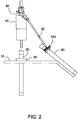
- a tubular string 20 is supported at a rig floor 10 by a spider 30.
- a running unit 40 is positioned proximate the tubular string 20.
- the running unit 40 is attached to a Top Drive (not shown).
- a pair of handling bails 50 is pivotally attached to the running unit 40. Hydraulic cylinders 60 are fixed between the running unit 40 and the bails 50. By operating the hydraulic cylinders 60, the bails 50 can be raised or lowered accordingly. An end of the bails 50 are attached to the remotely operated single joint elevator 100.
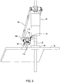
- Figures 2 and 3 illustrate the interaction between the single joint elevator 100 and the tubular 90.
- the single joint elevator 100 moves to an open configuration in order to allow the tubular 90 to be positioned within the single joint elevator 100.
- stops 110 on the single joint elevator 100 come in contact with the tubular 90 first, and these stops 110 are adapted to align an access opening of the single joint elevator 100 relative to the tubular 90.
- Figure 3 is another view of the single joint elevator 100 after the tubular 90 is positioned within the single joint elevator 100.
- the single joint elevator 100 moves from the open configuration to a closed configuration. In the closed configuration, the single joint elevator 100 is enclosed around the tubular 90 by closing a pair of closure members 115.
- the single joint elevator 100 may optionally include a sensing member (not shown) that is configured to sense when the tubular 90 is positioned in the single joint elevator 100. The sensing member may be activated even before the closure members 115 are closed.
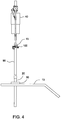
- Figure 4 is a view illustrating the running unit 40 aligning the tubular 90 with the tubular string 20.
- the running unit 40 is lifted along with the bails 50 which allow the single joint elevator 100 to slide upwards guided by the tubular 90 until the stops 110 of the single joint elevator 100 come in contact with a coupling 15 on the tubular 90.
- the tubular 90 is lifted further until it is off of the rig floor 10, and thereafter, hanging vertically as shown in Figure 4 . From this configuration, the tubular 90 can be stabbed into the coupling of the tubular string 20. Then, the running unit 40 can facilitate the connection of the tubular 90 with the tubular string 20 and lower the made up tubular string down.
- the single joint elevator 100 is moved from the closed configuration to the open configuration and the bails 50 are swung out.
- the joint elevator 100 may be moved to the open configuration and the bails 50 are swung out as the made up tubular is lowered down.
- the pair of closure members 115 of the single joint elevator 100 may include grippers (not shown).
- the running unit 40, the bails 50 and the single joint elevator 100 are lifted until the tubular 90 is raised off of the rig floor 10 as shown in Figure 4 .
- the bails 50 may be retracted until the tubular 90 is engaged and secured by the running unit 40.
- An example of retractable bails is described in U.S. Patent No. 6,527,047 to Bernd-Georg Pietras, which is herein incorporated by reference.
- the tubular 90 can be stabbed into the coupling of the tubular string 20.
- the grippers of the single joint elevator 100 may be released so that the running unit 40 can facilitate the connection of the tubular 90 with the tubular string 20.
- Figure 5 is an isometric view of the single joint elevator 100 in the closed configuration. As shown, closure members 115 of the single joint elevator 100 are closed.
- the single joint elevator 100 is provided with the stops 110 which are used to align the single joint elevator 100 relative to the tubular 90.
- the single joint elevator 100 is also provided with fixtures 80, such as bolts for the connection to the bails 50.
- the single joint elevator 100 may also include an adapter 120 for use with the tubular.
- Figure 6 shows the single joint elevator 100 with adapters 125 suited for smaller casings. Therefore, depending on which adapter is used, the single joint elevator 100 may be utilized for a wide range of casing sizes. Typically, the inside diameter of the adapters is smaller than the O.D. of the coupling of the tubular.
- Figures 7A and 7B are views of the single joint elevator 100 in an open configuration and a closed configuration.
- the closure members 115 are pivotally fixed by a hinge pin 140 to the housing 150.
- Gear segments 160 are coupled to the closure members 115 in a manner such that the center of the gear segments 160 is proximate the center of the hinge pin 140.
- a power assembly comprising of pinions 170 and motors 180 are engaged with the gear segments 16.
- One motor 180 drives one pinion 170 in a clockwise direction and the second motor 180 drives the second pinion 170 in a counter-clockwise direction.
- the pinions 170 will rotate the closure members 115 until the closure members 115 are opened.
- FIG. 130 shows the direction of the force due to the weight of the tubular 90 during lifting of the casing directly from the V-door at rig side (see Figure 3 ).
- the direction of the force goes to the center of the pivot point of the hinge pin 140. Therefore, the closure members 115 experience a relatively small opening torque applied due to the weight of the tubular 90 as compared to a relatively large torque applied by the motors 180, thereby maintaining the closure members 115 in the closed position.
- the motors 180 are standard equipment on the market. Typically, the motor includes brakes having multi-plates. These kinds of brakes are spring loaded and can be released hydraulically. For enhanced safety, the motors can be combined with locking elements like a pin lock. Other possibilities for locking the closure members are ratchets at the pinion or gear segments or locking bolts at the closure members.
- the locking mechanisms may be locally operated, remotely operated or a combination thereof. Further, the operation of the locking mechanisms may be integrated into the control logic for the operation of the joint elevator.
- the single joint elevator 100 may include a lock assembly 185 as shown in Figures 9A and 9B .
- the lock assembly 185 may be configured to send a signal to the motors 180 to indicate that the single joint elevator 100 is lifting the tubular 90.
- the signal is used by the motor 180 to lock the brakes so that the single joint elevator 100 cannot be opened.
- the single joint elevator 100 moves from the open configuration to the close configuration which causes the closure members 115 to close around the tubular (see Figure 3 ). Thereafter, the running unit 40 is lifted along with the bails 50 which cause the single joint elevator 100 to slide upwards guided by the tubular 90 until the stops 110 of the single joint elevator 100 come in contact with the coupling 15 on the tubular 90 as shown in Figure 9A .
- the coupling 15 loads a ring 175 which causes a bushing 190 to compress a biasing member 195, such as a spring, as shown in Figure 9B .
- the compression of the biasing member 195 causes the ring 175 to be displaced on the outside of the housing 150 perpendicular to the operating plane of the closure members 115. This action prevents inadvertent release of the tubular 90 from the single joint elevator 100.
- the other embodiments described herein may use a similar lock assembly to generate a signal that locks the power assembly (e.g. motors or cylinders) and/or the use of a similar ring assembly which is used to prevent inadvertent release of the tubular 90.
- Operation of the single joint elevator 100 may be incorporated as part of a safety interlock system which may be configured to confirm that a tubular is securely held by the single joint elevator 100 and prevent inadvertent release of the tubular from the single joint elevator 100.
- the signal which locks the power assembly may be incorporated in the safety interlock of the entire tubular handling system.
- the safety interlock system may be further configured to interact with the control systems of other tubular handling equipment in use simultaneously with the single joint elevator 100 (such as top drive, casing running tools, rig floor spider, tongs, etc.) in order to ensure appropriate coordination of the tubular handling operation.
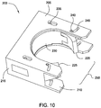
- FIG 10 is a view illustrating a remotely operated single joint elevator 200 according to one embodiment of the invention.
- the single joint elevator 200 includes a housing 215 that encloses the moving parts.
- the housing 215 generally includes an upper plate 205 and a lower plate 210.
- the upper and lower plates 205, 210 each define an access opening 250 in one side of the housing 215, through which a tubular may be moved into and out of the single joint elevator 200.
- closure members 225 closed around it.
- the closure members 225 shown in Figure 10 do not necessarily close the entire space of the access opening 250, but in some embodiments it is contemplated that the closure members 225 may indeed close the entire access opening 250.
- the closure members 225 are hingedly connected to a movable body 230, which is held within the housing 215. As such, the closure members 225 are able to pivot in order to selectively open and close the access opening 250.
- Each closure member 225 furthermore, has a closure member pin 240 protruding above and/or below it.
- the closure member pins 240 are engaged within respective guide slots 245 within the upper and/or lower plates 205, 210. Therefore, pivotal motion of the closure members 225 may be guided by the travel of the closure member pins 240 within their respective guide slots 245.
- the guide slots 245 define a "J", with the closure member pins 240 located at one end of the "J." It is evident that in Figure 10 with the closure member pins 240 in their illustrated configuration within their respective slots 245, the slot 245 configuration dictates that the closure members 225 may not be able to pivot until the closure member pins 240 have travelled laterally toward the access opening 250. As such, as shown in Fig 10 , the closure members 225 are retained in the closed configuration. As described, the guide slots are in the plates 205, 210 and the pin attached to the closure member 225, however it should be noted that the pins and/or the slots are interchangeable such that they may be part of either component, without departing from principles of the present invention.
- the housing 215, the access opening 250, the moveable body 230 and the closure members 225 are so shaped and sized to provide a close fit around the cylindrical bodies of the tubulars being handled by the single joint elevator 200.
- adapters may be fitted to the inner concave surface of the body 230 and the closure members 225, as appropriate.
- Figure 11 is a view illustrating the single joint elevator in an open configuration. It can be seen that the closure member pins 240 are now located at the opposite ends of the guide slots 245, and the closure members 225 have been pivoted about the hinges connecting them to the body 230. Also evident in Figure 11 is that the closure members 225 and the body 230 have travelled towards the access opening 250 in the housing 215.
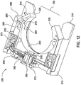
- FIG 12 is a view illustrating the components of the single joint elevator 200.
- the upper plate 205 has been omitted to reveal the inner workings, and the major components are shown hollowed to further illustrate their juxtaposition within the single joint elevator 200.
- each closure member 225 has a hinge tab portion 295, through which a hinge pin 280 is located.
- the hinge pin 280 is also located through a part of the movable body 230.
- the back sides (or outside surfaces) of the closure member hinge tab portions 295 interact with inner surfaces on the side of the housing 215. More specifically, the closure member hinge tab portions 295 interact with a cam surface 290 and a locking surface 285 of the housing 215.
- the body 230 is movable within the housing 215 laterally towards and away from the access opening 250. This is accomplished by pressurizing against power assembly comprising a piston 265 and a chamber 270. It is contemplated that the piston 265 may be hydraulic or pneumatic. In an alternative embodiment, a spring or other form of biasing member may be provided within the chamber 270, such that the body 230 may be biased to be positioned away from the access opening 250. As such, in this embodiment, the closure members 225 may therefore be biased to the closed configuration.
- a further (and optional) feature illustrated in Figure 12 is a latch 275 configured to retain the body 230 from moving toward the access opening 250.
- the latch 275 and its associated mechanism are illustrated on one side of the housing 215 for clarity however; it is contemplated that a similar arrangement may be present on the other side. Additionally, similar arrangements may be provided in corresponding locations on the underside of the body 230.
- the latch 275 is fixed to the housing 215, and, as shown here, engages with a latch pin 235.
- the latch pin 235 is fixed to the body 230. Therefore in the configuration shown Figure 12 , the body 230 is restrained from lateral motion by the latch 275.
- the latch 275 is movable to enable engagement and disengagement with the latch pin 235, this movement being selectively facilitated by a latch mechanism 255 attached to the latch 275.
- the latch 275 itself may be sprung or biased, preferably to the closed (or "latched") configuration as shown in Figure 12 .
- a latch control may also be provided to prevent the inadvertent release of the latch 275.
- a latch trigger 260 When the cylinder 265 is attached to a bracket 220 which will unlock the latch 275 via the latch linkage mechanism 255 before engaging the body 230.
- the trigger 260 continues to open the latch 275 as the trigger 260 pass the linkage mechanism 255 and the pin 235, connected to the body 230, moves away from the latch 275.
- the latch pin 235 will clear the latch 275 simultaneously with the trigger 260 clearing the linkage 255.
- the linkage mechanism 255 will not move in opposite direction therefore the latch trigger 260 contains a spring that allows it to retract during the closing function as it passes the Linkage mechanism 255.
- An indicator may be incorporated as part of a safety interlock system.
- Such a system may be configured to confirm that a tubular is securely held by the single joint elevator 200 and prevent inadvertent release of the tubular from the single joint elevator 200.
- the safety interlock system may be further configured to interact with the control systems of other tubular handling equipment in use simultaneously with the single joint elevator 200 (such as top drive, casing running tools, rig floor spider, tongs, etc.) in order to ensure appropriate coordination of the tubular handling operation.
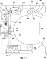
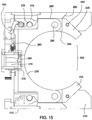
- Figures 13-15 are views illustrating the single joint elevator 200 as the single joint elevator 200 is operated from the open configuration to the closed configuration. It is envisaged that a tubular is moved into the access opening 250 such that its longitudinal axis extends substantially perpendicular to the plane of the illustration. As illustrated in Figure 13 , the piston 265 has displaced the body 230 laterally toward the access opening 250. The latch 275 is disengaged from the latch pin 235 and the trigger 260 is positioned away from the latch mechanism 255. The closure members 225 are in the open configuration, and the back sides of the closure member hinge tab portions 295 are bearing against respective cam surfaces 290 of the housing 215.
- the single joint elevator 200 is shown moving from the open configuration to the closed configuration.
- the backsides of the closure member hinge tab portions 295 are bearing against the juncture of the respective cam surfaces 290 and locking surfaces 285.
- the latch pin 235 is causing the latch 275 to open, and the latch mechanism 255 is interacting with the trigger 260.
- the single joint elevator is the closed configuration.
- the closure members 225 are in their closed positions, thereby preventing the tubular from exiting the access opening 250.
- the backsides of the closure member hinge tab portions 295 are bearing against the respective locking surfaces 285.
- the latch 275 has closed around the latch pin 235, thereby preventing further movement of the body 230 relative to the housing 215.
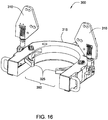
- FIG 16 is a view illustrating a remotely operated single joint elevator according to one embodiment of the invention.
- the single joint elevator 300 includes a housing 315 that encloses the moving parts.
- An access opening 350 is defined on one side of the housing 315, through which a tubular may be moved into and out of the single joint elevator 300.
- a tubular When a tubular is positioned within the single joint elevator 300, it may be retained by closure members 325 closed around it.
- the closure members 325 shown in Figure 16 do not necessarily close the entire space of the access opening 350, but in some embodiments it is contemplated that the closure members 325 may close the entire access opening 350.
- the single joint elevator 300 also includes connection plates 310 which are used to connect the single joint elevator 300 to the bails. In other embodiments, the single joint elevator 300 may be connected to the bails by any type of connection assembly, such as lifting lugs on the single joint elevator on which rings on the bails fit over.
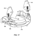
- Figure 17 is a bottom view of the single joint elevator 300.
- the single joint elevator 300 includes a power assembly comprising a cylinder 365 and a wedge block 335.
- the cylinder 365 may be hydraulic or pneumatic.
- a spring or other form of biasing member may be provided to bias the wedge block 335.
- the cylinder 365 and the wedge block 335 are configured to selectively move the closure members 325 between an open position and a closed position.
- the single joint elevator 300 may also include an adapter for use with the tubular which allows the single joint elevator 300 to be utilized for a wide range of casing sizes. Typically, the inside diameter of the adapter is smaller than the O.D. of the coupling of the tubular.
- FIGS 18A and 18B are views of the single joint elevator 300 in an open configuration and a closed configuration.
- the closure members 325 are hingedly connected to the housing 315 via a hinge pin 380.
- the closure members 325 are able to pivot in order to selectively open and close the access opening 350.
- Each closure member 325 includes a guide slot 390 that interacts with a closure member pin 340 protruding from the wedge block 335. As a result, pivotal motion of the closure members 325 may be guided by the travel of the closure member pins 340 within their respective guide slots 390.
- Each closure member 325 also has a side portion 385 which interacts with the surfaces on the wedge block 335. More specifically, the side portion 385 interacts with a cam surface 305 and a locking surface 320 of the wedge block 335.
- the movement of the wedge block 335 towards and away from the access opening 350, combined with the interaction between the closure member pins 340 and the guide slots 390 causes the side portion 385 of the closure member 325 to bear against the respective cam surfaces 305 while the closure members 325 are opening or closing.
- the side portion 385 of the closure member 325 interact with the respective locking surfaces 320. As such, in this closed configuration, the closure members 325 are prevented from pivoting outwards.
- the guide slots are in the closure member 325 and the pin attached to the wedge block 335, however it should be noted that the pins and/or the slots are interchangeable such that they may be part of either component, without departing from principles of the present invention.
- the body wedge block 335 is movable within the housing 315 laterally towards and away from the access opening 350. This is accomplished by pressurizing the cylinder 365. It is envisaged that a tubular is moved into the access opening 350 such that its longitudinal axis extends substantially perpendicular to the plane of the illustration. As illustrated in Figure 18A , the cylinder 365 has displaced the wedge block 335 laterally toward the access opening 350.
- the closure members 325 are in the open position, and the side portion 385 of the closure members 335 are bearing against respective cam surfaces 305 of the wedge block 335.
- the single joint elevator 300 is the closed configuration.
- the closure members 325 are in their closed positions, thereby preventing the tubular from exiting the access opening 350.
- the cylinder 365 has displaced the wedge block 335 laterally away from the access opening 350, thereby causing the closure members 325 to move toward the access opening 350.
- the side portion 385 of the closure members 325 are bearing against the respective locking surfaces 320 of the wedge block 335.
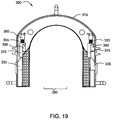
- Figure 19 is a view of an indicator 360 for use with the single joint elevator 300.
- the indicator 360 is used to indicate that the single joint elevator 300 is in the closed configuration.
- the indicator 360 is activated as the wedge block 335 is moved laterally away from the access opening 350 by the cylinder 365 thereby causing a slide member 375 to compress a biasing member 355, such as a spring.
- the compression of the biasing member 355 activates the indicator 360.
- the indicator 360 includes a plunger that is extended (or retracted) when the biasing member 335 is compressed.
- the configuration of the indicator 360 may be sensed optically, electrically, pneumatically or hydraulically.
- the indicator 360 may be incorporated as part of a safety interlock system.
- Such a system may be configured to confirm that a tubular is securely held by the single joint elevator 300 and prevent inadvertent release of the tubular from the single joint elevator 300.
- the safety interlock system may be further configured to interact with the control systems of other tubular handling equipment in use simultaneously with the single joint elevator 300 (such as top drive, casing running tools, rig floor spider, tongs, etc.) in order to ensure appropriate coordination of the tubular handling operation.
- Figure 20 is a back view of the single joint elevator 300.
- the single joint elevator 300 includes a lock assembly 370.
- the lock assembly 370 is configured to de-energize the source that controls the opening and closing functions of the single joint elevator 300, such as the cylinders 365 in this embodiment.
- the lock assembly 370 is used by a hydraulic system connected to the cylinder 365 to prevent opening of the single joint elevator 300.
- the single joint elevator 300 moves from the open configuration to the closed configuration which causes the closure members 325 to close around the tubular (similar to Figure 3 ). Thereafter, the running unit is lifted along with the bails which cause the single joint elevator 300 to slide upwards guided by the tubular until the single joint elevator 300 come in contact with the coupling on the tubular.
- the lock assembly 370 includes a plunger that is extended (or retracted) when the biasing member 395 elongates.
- the configuration of the lock assembly 370 may be sensed optically, electrically, pneumatically or hydraulically.
- the lock assembly 370 may be incorporated as part of a safety interlock system.
- Such a system may be configured to confirm that a tubular is securely held by the single joint elevator 300 and prevent inadvertent release of the tubular from the single joint elevator 300.
- the safety interlock system may be further configured to interact with the control systems of other tubular handling equipment in use simultaneously with the single joint elevator 300 (such as top drive, casing running tools, rig floor spider, tongs, etc.) in order to ensure appropriate coordination of the tubular handling operation.
- other embodiments described herein may use a similar lock assembly to de-energize the source that controls the opening and closing functions of the single joint elevator.
Landscapes
- Engineering & Computer Science (AREA)
- Life Sciences & Earth Sciences (AREA)
- Geology (AREA)
- Mining & Mineral Resources (AREA)
- Mechanical Engineering (AREA)
- Physics & Mathematics (AREA)
- Environmental & Geological Engineering (AREA)
- Fluid Mechanics (AREA)
- General Life Sciences & Earth Sciences (AREA)
- Geochemistry & Mineralogy (AREA)
- Types And Forms Of Lifts (AREA)
- Lift-Guide Devices, And Elevator Ropes And Cables (AREA)
Claims (14)
- Élévateur à articulation unique (100) utilisé pour la manutention d'un tube, l'élévateur à articulation unique comprenant:un boîtier (150) pourvu d'une ouverture d'accès configurée pour recevoir le tube;un premier élément de fermeture (115) connecté au boîtier par l'intermédiaire d'une goupille de charnière (140); etun second élément de fermeture (115) connecté au boîtier par l'intermédiaire de la goupille de charnière;caractérisé par:des éléments d'engrenage (160) couplés à une partie extérieure de chaque élément de fermeture; etun ensemble de puissance (170, 180) configuré pour faire tourner les éléments de fermeture par rapport au boîtier pour ouvrir et fermer de manière sélective l'ouverture d'accès de façon à actionner l'élévateur à distance.
- Élévateur à articulation unique selon la revendication 1, l'ensemble de puissance étant configuré pour faire tourner chaque élément de fermeture (115) dans une première direction pour ouvrir l'ouverture d'accès et dans une seconde direction pour fermer l'ouverture d'accès.
- Élévateur à articulation unique selon la revendication 1 ou 2, l'ensemble de puissance comprenant des pignons (170) qui sont configurés pour interagir avec les segments d'engrenage lorsque les éléments de fermeture tournent autour de la goupille de charnière.
- Élévateur à articulation unique selon l'une quelconque des revendications précédentes, comprenant, en outre, un assemblage de verrouillage (185) configuré pour verrouiller les éléments de fermeture après indication que le tube se trouve dans l'élévateur à articulation unique et que l'ouverture d'accès est fermée.
- Élévateur à articulation unique selon la revendication 4, l'assemblage de verrouillage étant configuré pour envoyer un signal qui empêche, par l'intermédiaire de l'ensemble de puissance, un déplacement des éléments de fermeture.
- Élévateur à articulation unique selon l'une quelconque des revendications précédentes, l'ensemble de puissance comprenant un premier moteur (180) qui fait tourner le premier élément de fermeture et un second moteur (180) qui fait tourner le second élément de fermeture.
- Élévateur à articulation unique selon la revendication 6, le premier moteur incluant des pignons qui interagissent avec les segments d'engrenage sur une partie extérieure du premier élément de fermeture et le second moteur incluant des pignons qui interagissent avec les segments d'engrenage sur une partie extérieure du second élément de fermeture.
- Procédé de manutention d'un tube (90) en utilisant un élévateur à articulation unique (100) télécommandé, le procédé comprenant:le positionnement de l'élévateur à articulation unique à proximité du tube, l'élévateur à articulation unique comprenant un boîtier (150) pourvu d'une ouverture d'accès et deux éléments de fermeture (115) connectés au boîtier de manière pivotante;l'activation d'un ensemble de puissance (70, 80) de l'élévateur à articulation unique pour faire tourner les deux éléments de fermeture de manière sélective par rapport au boîtier autour d'une goupille de charnière (140) pour exposer l'ouverture d'accès, l'ensemble de puissance étant configuré pour interagir avec des segments d'engrenage couplés à une partie extérieure de chaque élément de fermeture;la réception du tube dans l'ouverture d'accès; etl'activation de l'ensemble de puissance de l'élévateur à articulation unique pour faire tourner les deux éléments de fermeture de manière sélective par rapport au boîtier autour de la goupille de charnière pour fermer l'ouverture d'accès.
- Procédé selon la revendication 8, comprenant, en outre, une détection pour savoir si le tube est positionné dans l'élévateur à articulation unique.
- Procédé selon la revendication 9, comprenant, en outre, le verrouillage de l'élévateur à articulation unique de manière à ce que l'ouverture d'accès reste fermée.
- Procédé selon la revendication 8 ou 9, comprenant, en outre, l'exposition sélective de l'ouverture d'accès pour permettre la libération du tube de l'élévateur à articulation unique.
- Procédé selon la revendication 8, 9 ou 10, l'ensemble de puissance étant configuré pour faire tourner les éléments de fermeture dans l'élévateur à articulation unique.
- Procédé selon l'une quelconque des revendications 8 à 11, l'ensemble de puissance comprenant un premier moteur (180) qui fait tourner le premier élément de fermeture et un second moteur (180) qui fait tourner le second élément de fermeture.
- Procédé selon la revendication 13, le premier moteur incluant des pignons (170) qui interagissent avec les segments d'engrenage (160) sur une partie extérieure du premier élément de fermeture et le second moteur incluant des pignons (170) qui interagissent avec les segments d'engrenage (160) sur une partie extérieure du second élément de fermeture.
Applications Claiming Priority (3)
| Application Number | Priority Date | Filing Date | Title |
|---|---|---|---|
| US98312907P | 2007-10-26 | 2007-10-26 | |
| US12/258,357 US8215687B2 (en) | 2007-10-26 | 2008-10-24 | Remotely operated single joint elevator |
| EP08842839.6A EP2215325B1 (fr) | 2007-10-26 | 2008-10-25 | Élévateur de manoeuvre télécommandé |
Related Parent Applications (3)
| Application Number | Title | Priority Date | Filing Date |
|---|---|---|---|
| EP08842839.6A Division EP2215325B1 (fr) | 2007-10-26 | 2008-10-25 | Élévateur de manoeuvre télécommandé |
| EP08842839.6A Division-Into EP2215325B1 (fr) | 2007-10-26 | 2008-10-25 | Élévateur de manoeuvre télécommandé |
| EP08842839.6 Division | 2008-10-25 |
Publications (2)
| Publication Number | Publication Date |
|---|---|
| EP2631417A1 EP2631417A1 (fr) | 2013-08-28 |
| EP2631417B1 true EP2631417B1 (fr) | 2016-04-20 |
Family
ID=40580180
Family Applications (2)
| Application Number | Title | Priority Date | Filing Date |
|---|---|---|---|
| EP08842839.6A Active EP2215325B1 (fr) | 2007-10-26 | 2008-10-25 | Élévateur de manoeuvre télécommandé |
| EP13165772.8A Active EP2631417B1 (fr) | 2007-10-26 | 2008-10-25 | Élévateur de manoeuvre télécommandé |
Family Applications Before (1)
| Application Number | Title | Priority Date | Filing Date |
|---|---|---|---|
| EP08842839.6A Active EP2215325B1 (fr) | 2007-10-26 | 2008-10-25 | Élévateur de manoeuvre télécommandé |
Country Status (5)
| Country | Link |
|---|---|
| US (2) | US8215687B2 (fr) |
| EP (2) | EP2215325B1 (fr) |
| AU (1) | AU2008315508B2 (fr) |
| CA (2) | CA2702809C (fr) |
| WO (1) | WO2009053945A2 (fr) |
Families Citing this family (17)
| Publication number | Priority date | Publication date | Assignee | Title |
|---|---|---|---|---|
| US8141923B2 (en) * | 2007-01-19 | 2012-03-27 | Frank's Casing Crew And Rental Tools, Inc. | Single joint elevator having deployable jaws |
| AU2008340872B2 (en) * | 2007-12-21 | 2013-08-01 | Vestas Wind Systems A/S | A method for handling and/or servicing components of a wind turbine and a gripping apparatus for performing the method |
| DE102009039022A1 (de) | 2009-08-28 | 2011-03-03 | Bentec Gmbh Drilling & Oilfield Systems | Handhabungsgerät für Bohrgestänge, insbesondere so genannter Pipehandler oder so genannter Topdrive mit Pipehandler, und Betriebsverfahren dafür |
| US9175527B2 (en) | 2010-03-24 | 2015-11-03 | 2M-Tek, Inc. | Apparatus for handling tubulars |
| WO2012100019A1 (fr) | 2011-01-21 | 2012-07-26 | 2M-Tek, Inc. | Dispositif et procédé pour descendre des tubulaires |
| DE102013010022A1 (de) * | 2013-06-17 | 2014-12-18 | Herrenknecht Vertical Gmbh | Elevator für eine Bohranlage |
| US9206655B2 (en) * | 2014-03-14 | 2015-12-08 | David L. Sipos | 360 degree shoulder clamp elevator and method of use |
| US9422777B2 (en) * | 2014-06-12 | 2016-08-23 | Foley Patents, Llc | Elevator assembly with reversible insert |
| US20170088401A1 (en) * | 2015-09-24 | 2017-03-30 | Quality Rental Tools, Inc. | Method and apparatus for handling lift subs and other objects |
| CN105215603B (zh) * | 2015-10-27 | 2016-10-12 | 希姆斯电梯(中国)有限公司 | 一种能保证加强筋、支撑柱与导轨焊接垂直度的工装结构 |
| CN105269229B (zh) * | 2015-12-07 | 2017-03-29 | 希姆斯电梯(中国)有限公司 | 一种能实现导轨焊接垂直度的调节工装结构 |
| WO2017152263A1 (fr) * | 2016-03-07 | 2017-09-14 | Goliath Snubbing Ltd. | Système de support de tuyau vertical |
| US10415328B2 (en) | 2016-06-23 | 2019-09-17 | Frank's International, Llc | Clamp-on single joint manipulator for use with single joint elevator |
| US10233704B2 (en) | 2016-09-23 | 2019-03-19 | Frank's International, Llc | Integrated tubular handling system |
| US10801280B2 (en) | 2016-09-23 | 2020-10-13 | Frank's International, Llc | Integrated tubular handling system and method |
| JP6750154B2 (ja) * | 2017-12-07 | 2020-09-02 | アダマンド並木精密宝石株式会社 | ロボットハンド |
| US11970915B2 (en) | 2022-07-06 | 2024-04-30 | Weatherford Technology Holdings, Llc | Spider load indicator |
Family Cites Families (23)
| Publication number | Priority date | Publication date | Assignee | Title |
|---|---|---|---|---|
| US1452127A (en) * | 1922-01-09 | 1923-04-17 | Charles E Sitzman | Rod elevator |
| US3881761A (en) * | 1970-10-29 | 1975-05-06 | Alsacienne Atom | Automatic mechanical tongs with open and closed stable positions |
| US3937515A (en) * | 1974-11-22 | 1976-02-10 | Byron Jackson Inc. | Head for pipe rackers |
| US4126348A (en) * | 1977-05-05 | 1978-11-21 | Bj-Hughes, Inc. | Universal handling head for a pipe racker |
| US4438902A (en) * | 1979-12-28 | 1984-03-27 | Deepsea Ventures, Inc. | Pipe string lift system |
| DE3031027C2 (de) * | 1980-08-16 | 1986-02-20 | Stahl- Und Apparatebau Hans Leffer Gmbh, 6602 Dudweiler | Spannschelle für Bohrrohre |
| US4360230A (en) * | 1980-09-12 | 1982-11-23 | The United States Of America As Represented By The United States Department Of Energy | Self locking coupling mechanism for engaging and moving a load |
| US4461607A (en) * | 1982-09-22 | 1984-07-24 | The Heil Co. | Refuse container gripping apparatus |
| US4647099A (en) * | 1986-02-04 | 1987-03-03 | Hughes Tool Company | Lifting head |
| US4765401A (en) * | 1986-08-21 | 1988-08-23 | Varco International, Inc. | Apparatus for handling well pipe |
| US4811635A (en) * | 1987-09-24 | 1989-03-14 | Falgout Sr Thomas E | Power tong improvement |
| US5340182A (en) * | 1992-09-04 | 1994-08-23 | Varco International, Inc. | Safety elevator |
| US5863086A (en) * | 1994-11-21 | 1999-01-26 | Mcneilus Truck And Manufacturing, Inc. | Container holding and lifting device |
| US5671961A (en) * | 1995-10-13 | 1997-09-30 | Buck; David A. | Back-up power tongs |
| US5904075A (en) * | 1996-10-11 | 1999-05-18 | Buck; David A. | Interlocking jaw power tongs |
| GB2321867A (en) * | 1997-02-07 | 1998-08-12 | Weatherford Lamb | Apparatus for gripping a tubular |
| GB2340859A (en) | 1998-08-24 | 2000-03-01 | Weatherford Lamb | Method and apparatus for facilitating the connection of tubulars using a top drive |
| CA2256298C (fr) * | 1998-12-18 | 2008-01-29 | Farr Canada Ltd. | Pince pour tube de puits |
| US7032678B2 (en) * | 1999-10-01 | 2006-04-25 | Frank's Casing Crew And Rental Tools, Inc. | Horseshoe shaped elevator and method for using same |
| CA2512328C (fr) * | 2004-07-19 | 2009-10-06 | Weatherford/Lamb, Inc. | Blocage de securite pour ascenseurs |
| US7216717B2 (en) * | 2005-02-25 | 2007-05-15 | Blohm + Voss Repair Gmbh | Dual elevator system and method |
| US8141923B2 (en) * | 2007-01-19 | 2012-03-27 | Frank's Casing Crew And Rental Tools, Inc. | Single joint elevator having deployable jaws |
| US8240391B2 (en) * | 2007-05-09 | 2012-08-14 | Frank's Casing Crew And Rental Tools, Inc. | Single joint elevator with gripping jaws and method of hoisting a tubular member |
-
2008
- 2008-10-24 US US12/258,357 patent/US8215687B2/en active Active
- 2008-10-25 WO PCT/IB2008/054415 patent/WO2009053945A2/fr active Application Filing
- 2008-10-25 EP EP08842839.6A patent/EP2215325B1/fr active Active
- 2008-10-25 EP EP13165772.8A patent/EP2631417B1/fr active Active
- 2008-10-25 CA CA2702809A patent/CA2702809C/fr active Active
- 2008-10-25 AU AU2008315508A patent/AU2008315508B2/en active Active
- 2008-10-25 CA CA2833845A patent/CA2833845C/fr active Active
-
2012
- 2012-06-13 US US13/495,914 patent/US8496280B2/en active Active
Also Published As
| Publication number | Publication date |
|---|---|
| CA2833845C (fr) | 2016-02-23 |
| US20120247786A1 (en) | 2012-10-04 |
| WO2009053945A2 (fr) | 2009-04-30 |
| US8215687B2 (en) | 2012-07-10 |
| US8496280B2 (en) | 2013-07-30 |
| CA2702809A1 (fr) | 2009-04-30 |
| EP2215325A2 (fr) | 2010-08-11 |
| CA2702809C (fr) | 2014-05-06 |
| AU2008315508B2 (en) | 2012-07-05 |
| AU2008315508A1 (en) | 2009-04-30 |
| WO2009053945A3 (fr) | 2012-01-05 |
| CA2833845A1 (fr) | 2009-04-30 |
| US20090110535A1 (en) | 2009-04-30 |
| EP2215325B1 (fr) | 2014-01-22 |
| EP2631417A1 (fr) | 2013-08-28 |
Similar Documents
| Publication | Publication Date | Title |
|---|---|---|
| EP2631417B1 (fr) | Élévateur de manoeuvre télécommandé | |
| US7665530B2 (en) | Tubular grippers and top drive systems | |
| CA2520072C (fr) | Procede et appareil de manipulation de materiel tubulaire pour puits de forage | |
| EP2495390B1 (fr) | Élévateur de joint unique avec mâchoires déployables | |
| US7762343B2 (en) | Apparatus and method for handling pipe | |
| US20060185854A1 (en) | Horseshoe shaped elevator and method for using same | |
| US20030177870A1 (en) | High torque power tong | |
| US6568479B2 (en) | Horseshoe shaped elevator and method for using same | |
| US10900298B2 (en) | Large diameter tubular lifting apparatuses and methods | |
| EP2881535B1 (fr) | Outil de manipulation de matériel tubulaire | |
| AU2012233027B2 (en) | Remotely operated single joint elevator | |
| US10030454B2 (en) | Tubular handling tool | |
| EP3460171B1 (fr) | Appareils et procédés de levage tubulaire de grand diamètre |
Legal Events
| Date | Code | Title | Description |
|---|---|---|---|
| PUAI | Public reference made under article 153(3) epc to a published international application that has entered the european phase |
Free format text: ORIGINAL CODE: 0009012 |
|
| AC | Divisional application: reference to earlier application |
Ref document number: 2215325 Country of ref document: EP Kind code of ref document: P |
|
| AK | Designated contracting states |
Kind code of ref document: A1 Designated state(s): AT BE BG CH CY CZ DE DK EE ES FI FR GB GR HR HU IE IS IT LI LT LU LV MC MT NL NO PL PT RO SE SI SK TR |
|
| RIN1 | Information on inventor provided before grant (corrected) |
Inventor name: LIESS, MARTIN Inventor name: HOOKER, II, JOHN D. Inventor name: WOOD, KEVIN Inventor name: HELMS, MARTIN Inventor name: HEIDECKE, KARSTEN Inventor name: PIETRAS, BERND-GEORG |
|
| RIN1 | Information on inventor provided before grant (corrected) |
Inventor name: WOOD, KEVIN Inventor name: HOOKER, II, JOHN D. Inventor name: HEIDECKE, KARSTEN Inventor name: HELMS, MARTIN Inventor name: PIETRAS, BERND-GEORG Inventor name: LIESS, MARTIN |
|
| 17P | Request for examination filed |
Effective date: 20140224 |
|
| RBV | Designated contracting states (corrected) |
Designated state(s): AT BE BG CH CY CZ DE DK EE ES FI FR GB GR HR HU IE IS IT LI LT LU LV MC MT NL NO PL PT RO SE SI SK TR |
|
| RAP1 | Party data changed (applicant data changed or rights of an application transferred) |
Owner name: WEATHERFORD/LAMB, INC. |
|
| RAP1 | Party data changed (applicant data changed or rights of an application transferred) |
Owner name: WEATHERFORD TECHNOLOGY HOLDINGS, LLC |
|
| GRAP | Despatch of communication of intention to grant a patent |
Free format text: ORIGINAL CODE: EPIDOSNIGR1 |
|
| RIC1 | Information provided on ipc code assigned before grant |
Ipc: E21B 19/06 20060101AFI20151020BHEP |
|
| INTG | Intention to grant announced |
Effective date: 20151106 |
|
| GRAS | Grant fee paid |
Free format text: ORIGINAL CODE: EPIDOSNIGR3 |
|
| GRAA | (expected) grant |
Free format text: ORIGINAL CODE: 0009210 |
|
| AC | Divisional application: reference to earlier application |
Ref document number: 2215325 Country of ref document: EP Kind code of ref document: P |
|
| AK | Designated contracting states |
Kind code of ref document: B1 Designated state(s): AT BE BG CH CY CZ DE DK EE ES FI FR GB GR HR HU IE IS IT LI LT LU LV MC MT NL NO PL PT RO SE SI SK TR |
|
| REG | Reference to a national code |
Ref country code: GB Ref legal event code: FG4D |
|
| REG | Reference to a national code |
Ref country code: CH Ref legal event code: EP |
|
| REG | Reference to a national code |
Ref country code: AT Ref legal event code: REF Ref document number: 792669 Country of ref document: AT Kind code of ref document: T Effective date: 20160515 |
|
| REG | Reference to a national code |
Ref country code: IE Ref legal event code: FG4D |
|
| REG | Reference to a national code |
Ref country code: DE Ref legal event code: R096 Ref document number: 602008043814 Country of ref document: DE |
|
| REG | Reference to a national code |
Ref country code: NL Ref legal event code: FP |
|
| REG | Reference to a national code |
Ref country code: NO Ref legal event code: T2 Effective date: 20160420 |
|
| REG | Reference to a national code |
Ref country code: LT Ref legal event code: MG4D |
|
| REG | Reference to a national code |
Ref country code: AT Ref legal event code: MK05 Ref document number: 792669 Country of ref document: AT Kind code of ref document: T Effective date: 20160420 |
|
| PG25 | Lapsed in a contracting state [announced via postgrant information from national office to epo] |
Ref country code: LT Free format text: LAPSE BECAUSE OF FAILURE TO SUBMIT A TRANSLATION OF THE DESCRIPTION OR TO PAY THE FEE WITHIN THE PRESCRIBED TIME-LIMIT Effective date: 20160420 Ref country code: FI Free format text: LAPSE BECAUSE OF FAILURE TO SUBMIT A TRANSLATION OF THE DESCRIPTION OR TO PAY THE FEE WITHIN THE PRESCRIBED TIME-LIMIT Effective date: 20160420 Ref country code: PL Free format text: LAPSE BECAUSE OF FAILURE TO SUBMIT A TRANSLATION OF THE DESCRIPTION OR TO PAY THE FEE WITHIN THE PRESCRIBED TIME-LIMIT Effective date: 20160420 |
|
| PG25 | Lapsed in a contracting state [announced via postgrant information from national office to epo] |
Ref country code: PT Free format text: LAPSE BECAUSE OF FAILURE TO SUBMIT A TRANSLATION OF THE DESCRIPTION OR TO PAY THE FEE WITHIN THE PRESCRIBED TIME-LIMIT Effective date: 20160822 Ref country code: SE Free format text: LAPSE BECAUSE OF FAILURE TO SUBMIT A TRANSLATION OF THE DESCRIPTION OR TO PAY THE FEE WITHIN THE PRESCRIBED TIME-LIMIT Effective date: 20160420 Ref country code: LV Free format text: LAPSE BECAUSE OF FAILURE TO SUBMIT A TRANSLATION OF THE DESCRIPTION OR TO PAY THE FEE WITHIN THE PRESCRIBED TIME-LIMIT Effective date: 20160420 Ref country code: ES Free format text: LAPSE BECAUSE OF FAILURE TO SUBMIT A TRANSLATION OF THE DESCRIPTION OR TO PAY THE FEE WITHIN THE PRESCRIBED TIME-LIMIT Effective date: 20160420 Ref country code: HR Free format text: LAPSE BECAUSE OF FAILURE TO SUBMIT A TRANSLATION OF THE DESCRIPTION OR TO PAY THE FEE WITHIN THE PRESCRIBED TIME-LIMIT Effective date: 20160420 Ref country code: AT Free format text: LAPSE BECAUSE OF FAILURE TO SUBMIT A TRANSLATION OF THE DESCRIPTION OR TO PAY THE FEE WITHIN THE PRESCRIBED TIME-LIMIT Effective date: 20160420 Ref country code: GR Free format text: LAPSE BECAUSE OF FAILURE TO SUBMIT A TRANSLATION OF THE DESCRIPTION OR TO PAY THE FEE WITHIN THE PRESCRIBED TIME-LIMIT Effective date: 20160721 |
|
| PG25 | Lapsed in a contracting state [announced via postgrant information from national office to epo] |
Ref country code: BE Free format text: LAPSE BECAUSE OF FAILURE TO SUBMIT A TRANSLATION OF THE DESCRIPTION OR TO PAY THE FEE WITHIN THE PRESCRIBED TIME-LIMIT Effective date: 20160420 Ref country code: IT Free format text: LAPSE BECAUSE OF FAILURE TO SUBMIT A TRANSLATION OF THE DESCRIPTION OR TO PAY THE FEE WITHIN THE PRESCRIBED TIME-LIMIT Effective date: 20160420 |
|
| REG | Reference to a national code |
Ref country code: DE Ref legal event code: R097 Ref document number: 602008043814 Country of ref document: DE |
|
| PG25 | Lapsed in a contracting state [announced via postgrant information from national office to epo] |
Ref country code: RO Free format text: LAPSE BECAUSE OF FAILURE TO SUBMIT A TRANSLATION OF THE DESCRIPTION OR TO PAY THE FEE WITHIN THE PRESCRIBED TIME-LIMIT Effective date: 20160420 Ref country code: CZ Free format text: LAPSE BECAUSE OF FAILURE TO SUBMIT A TRANSLATION OF THE DESCRIPTION OR TO PAY THE FEE WITHIN THE PRESCRIBED TIME-LIMIT Effective date: 20160420 Ref country code: SK Free format text: LAPSE BECAUSE OF FAILURE TO SUBMIT A TRANSLATION OF THE DESCRIPTION OR TO PAY THE FEE WITHIN THE PRESCRIBED TIME-LIMIT Effective date: 20160420 Ref country code: DK Free format text: LAPSE BECAUSE OF FAILURE TO SUBMIT A TRANSLATION OF THE DESCRIPTION OR TO PAY THE FEE WITHIN THE PRESCRIBED TIME-LIMIT Effective date: 20160420 Ref country code: EE Free format text: LAPSE BECAUSE OF FAILURE TO SUBMIT A TRANSLATION OF THE DESCRIPTION OR TO PAY THE FEE WITHIN THE PRESCRIBED TIME-LIMIT Effective date: 20160420 |
|
| PLBE | No opposition filed within time limit |
Free format text: ORIGINAL CODE: 0009261 |
|
| STAA | Information on the status of an ep patent application or granted ep patent |
Free format text: STATUS: NO OPPOSITION FILED WITHIN TIME LIMIT |
|
| 26N | No opposition filed |
Effective date: 20170123 |
|
| PG25 | Lapsed in a contracting state [announced via postgrant information from national office to epo] |
Ref country code: SI Free format text: LAPSE BECAUSE OF FAILURE TO SUBMIT A TRANSLATION OF THE DESCRIPTION OR TO PAY THE FEE WITHIN THE PRESCRIBED TIME-LIMIT Effective date: 20160420 |
|
| REG | Reference to a national code |
Ref country code: CH Ref legal event code: PL |
|
| REG | Reference to a national code |
Ref country code: IE Ref legal event code: MM4A |
|
| REG | Reference to a national code |
Ref country code: FR Ref legal event code: ST Effective date: 20170630 |
|
| PG25 | Lapsed in a contracting state [announced via postgrant information from national office to epo] |
Ref country code: LI Free format text: LAPSE BECAUSE OF NON-PAYMENT OF DUE FEES Effective date: 20161031 Ref country code: CH Free format text: LAPSE BECAUSE OF NON-PAYMENT OF DUE FEES Effective date: 20161031 Ref country code: FR Free format text: LAPSE BECAUSE OF NON-PAYMENT OF DUE FEES Effective date: 20161102 |
|
| PG25 | Lapsed in a contracting state [announced via postgrant information from national office to epo] |
Ref country code: LU Free format text: LAPSE BECAUSE OF NON-PAYMENT OF DUE FEES Effective date: 20161025 |
|
| PG25 | Lapsed in a contracting state [announced via postgrant information from national office to epo] |
Ref country code: IE Free format text: LAPSE BECAUSE OF NON-PAYMENT OF DUE FEES Effective date: 20161025 |
|
| PG25 | Lapsed in a contracting state [announced via postgrant information from national office to epo] |
Ref country code: CY Free format text: LAPSE BECAUSE OF FAILURE TO SUBMIT A TRANSLATION OF THE DESCRIPTION OR TO PAY THE FEE WITHIN THE PRESCRIBED TIME-LIMIT Effective date: 20160420 Ref country code: HU Free format text: LAPSE BECAUSE OF FAILURE TO SUBMIT A TRANSLATION OF THE DESCRIPTION OR TO PAY THE FEE WITHIN THE PRESCRIBED TIME-LIMIT; INVALID AB INITIO Effective date: 20081025 |
|
| PG25 | Lapsed in a contracting state [announced via postgrant information from national office to epo] |
Ref country code: MT Free format text: LAPSE BECAUSE OF NON-PAYMENT OF DUE FEES Effective date: 20161031 Ref country code: IS Free format text: LAPSE BECAUSE OF FAILURE TO SUBMIT A TRANSLATION OF THE DESCRIPTION OR TO PAY THE FEE WITHIN THE PRESCRIBED TIME-LIMIT Effective date: 20160420 Ref country code: MC Free format text: LAPSE BECAUSE OF FAILURE TO SUBMIT A TRANSLATION OF THE DESCRIPTION OR TO PAY THE FEE WITHIN THE PRESCRIBED TIME-LIMIT Effective date: 20160420 |
|
| PG25 | Lapsed in a contracting state [announced via postgrant information from national office to epo] |
Ref country code: BG Free format text: LAPSE BECAUSE OF FAILURE TO SUBMIT A TRANSLATION OF THE DESCRIPTION OR TO PAY THE FEE WITHIN THE PRESCRIBED TIME-LIMIT Effective date: 20160420 |
|
| PG25 | Lapsed in a contracting state [announced via postgrant information from national office to epo] |
Ref country code: TR Free format text: LAPSE BECAUSE OF FAILURE TO SUBMIT A TRANSLATION OF THE DESCRIPTION OR TO PAY THE FEE WITHIN THE PRESCRIBED TIME-LIMIT Effective date: 20160420 |
|
| PGFP | Annual fee paid to national office [announced via postgrant information from national office to epo] |
Ref country code: NL Payment date: 20191014 Year of fee payment: 12 |
|
| REG | Reference to a national code |
Ref country code: NL Ref legal event code: RC Free format text: DETAILS LICENCE OR PLEDGE: RIGHT OF PLEDGE, ESTABLISHED Name of requester: DEUTSCHE BANK TRUST COMPANY AMERICAS Effective date: 20200723 |
|
| REG | Reference to a national code |
Ref country code: GB Ref legal event code: 732E Free format text: REGISTERED BETWEEN 20200813 AND 20200819 |
|
| REG | Reference to a national code |
Ref country code: GB Ref legal event code: 732E Free format text: REGISTERED BETWEEN 20201126 AND 20201202 |
|
| REG | Reference to a national code |
Ref country code: GB Ref legal event code: 732E Free format text: REGISTERED BETWEEN 20210225 AND 20210303 |
|
| REG | Reference to a national code |
Ref country code: NL Ref legal event code: MM Effective date: 20201101 |
|
| PG25 | Lapsed in a contracting state [announced via postgrant information from national office to epo] |
Ref country code: NL Free format text: LAPSE BECAUSE OF NON-PAYMENT OF DUE FEES Effective date: 20201101 |
|
| PGFP | Annual fee paid to national office [announced via postgrant information from national office to epo] |
Ref country code: DE Payment date: 20220831 Year of fee payment: 15 |
|
| PGFP | Annual fee paid to national office [announced via postgrant information from national office to epo] |
Ref country code: GB Payment date: 20230831 Year of fee payment: 16 |
|
| P01 | Opt-out of the competence of the unified patent court (upc) registered |
Effective date: 20230922 |
|
| PGFP | Annual fee paid to national office [announced via postgrant information from national office to epo] |
Ref country code: NO Payment date: 20231010 Year of fee payment: 16 |
|
| REG | Reference to a national code |
Ref country code: DE Ref legal event code: R119 Ref document number: 602008043814 Country of ref document: DE |
|
| PG25 | Lapsed in a contracting state [announced via postgrant information from national office to epo] |
Ref country code: DE Free format text: LAPSE BECAUSE OF NON-PAYMENT OF DUE FEES Effective date: 20240501 |